EP3717169B1 - Verfahren zum schweissen mit schmelz- und schweissvorrichtungen und deaktivierung der schmelzvorrichtung; zugehörige schweisseinrichtung - Google Patents
Verfahren zum schweissen mit schmelz- und schweissvorrichtungen und deaktivierung der schmelzvorrichtung; zugehörige schweisseinrichtung Download PDFInfo
- Publication number
- EP3717169B1 EP3717169B1 EP18842717.3A EP18842717A EP3717169B1 EP 3717169 B1 EP3717169 B1 EP 3717169B1 EP 18842717 A EP18842717 A EP 18842717A EP 3717169 B1 EP3717169 B1 EP 3717169B1
- Authority
- EP
- European Patent Office
- Prior art keywords
- welding
- weld
- melting device
- workpiece
- melting
- Prior art date
- Legal status (The legal status is an assumption and is not a legal conclusion. Google has not performed a legal analysis and makes no representation as to the accuracy of the status listed.)
- Active
Links
Images


Classifications
-
- B—PERFORMING OPERATIONS; TRANSPORTING
- B23—MACHINE TOOLS; METAL-WORKING NOT OTHERWISE PROVIDED FOR
- B23K—SOLDERING OR UNSOLDERING; WELDING; CLADDING OR PLATING BY SOLDERING OR WELDING; CUTTING BY APPLYING HEAT LOCALLY, e.g. FLAME CUTTING; WORKING BY LASER BEAM
- B23K26/00—Working by laser beam, e.g. welding, cutting or boring
- B23K26/346—Working by laser beam, e.g. welding, cutting or boring in combination with welding or cutting covered by groups B23K5/00 - B23K25/00, e.g. in combination with resistance welding
- B23K26/348—Working by laser beam, e.g. welding, cutting or boring in combination with welding or cutting covered by groups B23K5/00 - B23K25/00, e.g. in combination with resistance welding in combination with arc heating, e.g. tungsten inert gas [TIG], metal inert gas [MIG] or plasma welding
-
- B—PERFORMING OPERATIONS; TRANSPORTING
- B23—MACHINE TOOLS; METAL-WORKING NOT OTHERWISE PROVIDED FOR
- B23K—SOLDERING OR UNSOLDERING; WELDING; CLADDING OR PLATING BY SOLDERING OR WELDING; CUTTING BY APPLYING HEAT LOCALLY, e.g. FLAME CUTTING; WORKING BY LASER BEAM
- B23K26/00—Working by laser beam, e.g. welding, cutting or boring
- B23K26/352—Working by laser beam, e.g. welding, cutting or boring for surface treatment
- B23K26/354—Working by laser beam, e.g. welding, cutting or boring for surface treatment by melting
-
- B—PERFORMING OPERATIONS; TRANSPORTING
- B23—MACHINE TOOLS; METAL-WORKING NOT OTHERWISE PROVIDED FOR
- B23K—SOLDERING OR UNSOLDERING; WELDING; CLADDING OR PLATING BY SOLDERING OR WELDING; CUTTING BY APPLYING HEAT LOCALLY, e.g. FLAME CUTTING; WORKING BY LASER BEAM
- B23K26/00—Working by laser beam, e.g. welding, cutting or boring
- B23K26/70—Auxiliary operations or equipment
- B23K26/702—Auxiliary equipment
- B23K26/706—Protective screens
-
- B—PERFORMING OPERATIONS; TRANSPORTING
- B23—MACHINE TOOLS; METAL-WORKING NOT OTHERWISE PROVIDED FOR
- B23K—SOLDERING OR UNSOLDERING; WELDING; CLADDING OR PLATING BY SOLDERING OR WELDING; CUTTING BY APPLYING HEAT LOCALLY, e.g. FLAME CUTTING; WORKING BY LASER BEAM
- B23K9/00—Arc welding or cutting
- B23K9/06—Arrangements or circuits for starting the arc, e.g. by generating ignition voltage, or for stabilising the arc
- B23K9/067—Starting the arc
-
- B—PERFORMING OPERATIONS; TRANSPORTING
- B23—MACHINE TOOLS; METAL-WORKING NOT OTHERWISE PROVIDED FOR
- B23K—SOLDERING OR UNSOLDERING; WELDING; CLADDING OR PLATING BY SOLDERING OR WELDING; CUTTING BY APPLYING HEAT LOCALLY, e.g. FLAME CUTTING; WORKING BY LASER BEAM
- B23K9/00—Arc welding or cutting
- B23K9/095—Monitoring or automatic control of welding parameters
- B23K9/0956—Monitoring or automatic control of welding parameters using sensing means, e.g. optical
-
- B—PERFORMING OPERATIONS; TRANSPORTING
- B23—MACHINE TOOLS; METAL-WORKING NOT OTHERWISE PROVIDED FOR
- B23K—SOLDERING OR UNSOLDERING; WELDING; CLADDING OR PLATING BY SOLDERING OR WELDING; CUTTING BY APPLYING HEAT LOCALLY, e.g. FLAME CUTTING; WORKING BY LASER BEAM
- B23K9/00—Arc welding or cutting
- B23K9/16—Arc welding or cutting making use of shielding gas
- B23K9/164—Arc welding or cutting making use of shielding gas making use of a moving fluid
-
- B—PERFORMING OPERATIONS; TRANSPORTING
- B23—MACHINE TOOLS; METAL-WORKING NOT OTHERWISE PROVIDED FOR
- B23K—SOLDERING OR UNSOLDERING; WELDING; CLADDING OR PLATING BY SOLDERING OR WELDING; CUTTING BY APPLYING HEAT LOCALLY, e.g. FLAME CUTTING; WORKING BY LASER BEAM
- B23K9/00—Arc welding or cutting
- B23K9/16—Arc welding or cutting making use of shielding gas
- B23K9/173—Arc welding or cutting making use of shielding gas and of a consumable electrode
-
- B—PERFORMING OPERATIONS; TRANSPORTING
- B23—MACHINE TOOLS; METAL-WORKING NOT OTHERWISE PROVIDED FOR
- B23K—SOLDERING OR UNSOLDERING; WELDING; CLADDING OR PLATING BY SOLDERING OR WELDING; CUTTING BY APPLYING HEAT LOCALLY, e.g. FLAME CUTTING; WORKING BY LASER BEAM
- B23K9/00—Arc welding or cutting
- B23K9/235—Preliminary treatment
-
- B—PERFORMING OPERATIONS; TRANSPORTING
- B23—MACHINE TOOLS; METAL-WORKING NOT OTHERWISE PROVIDED FOR
- B23K—SOLDERING OR UNSOLDERING; WELDING; CLADDING OR PLATING BY SOLDERING OR WELDING; CUTTING BY APPLYING HEAT LOCALLY, e.g. FLAME CUTTING; WORKING BY LASER BEAM
- B23K10/00—Welding or cutting by means of a plasma
- B23K10/02—Plasma welding
- B23K10/022—Spot welding
-
- B—PERFORMING OPERATIONS; TRANSPORTING
- B23—MACHINE TOOLS; METAL-WORKING NOT OTHERWISE PROVIDED FOR
- B23K—SOLDERING OR UNSOLDERING; WELDING; CLADDING OR PLATING BY SOLDERING OR WELDING; CUTTING BY APPLYING HEAT LOCALLY, e.g. FLAME CUTTING; WORKING BY LASER BEAM
- B23K2101/00—Articles made by soldering, welding or cutting
- B23K2101/04—Tubular or hollow articles
- B23K2101/06—Tubes
-
- B—PERFORMING OPERATIONS; TRANSPORTING
- B23—MACHINE TOOLS; METAL-WORKING NOT OTHERWISE PROVIDED FOR
- B23K—SOLDERING OR UNSOLDERING; WELDING; CLADDING OR PLATING BY SOLDERING OR WELDING; CUTTING BY APPLYING HEAT LOCALLY, e.g. FLAME CUTTING; WORKING BY LASER BEAM
- B23K2101/00—Articles made by soldering, welding or cutting
- B23K2101/04—Tubular or hollow articles
- B23K2101/06—Tubes
- B23K2101/08—Tubes finned or ribbed
-
- B—PERFORMING OPERATIONS; TRANSPORTING
- B23—MACHINE TOOLS; METAL-WORKING NOT OTHERWISE PROVIDED FOR
- B23K—SOLDERING OR UNSOLDERING; WELDING; CLADDING OR PLATING BY SOLDERING OR WELDING; CUTTING BY APPLYING HEAT LOCALLY, e.g. FLAME CUTTING; WORKING BY LASER BEAM
- B23K2101/00—Articles made by soldering, welding or cutting
- B23K2101/04—Tubular or hollow articles
- B23K2101/10—Pipe-lines
Definitions
- This invention relates to the art of arc welding, for example as used to make circumferential girth welds between abutting steel pipe joints when fabricating subsea pipelines.
- the invention relates to a method of welding a workpiece and to a welding apparatus, and is concerned with improving the quality of arc welds while accelerating the overall welding process.
- the arc of a welding torch firstly creates a puddle or pool of molten metal before relative movement between the torch and the workpiece displaces the arc along a joint to be welded.
- a welding torch may be supported by a welding bug that moves circumferentially along a rail extending around the workpiece.
- the weld pool is non-uniform or inhomogeneous because it contains various metallic phases and possibly even gas bubbles. Also, the weld pool often leaves a local bead at the initiation point that has to be ground off in a subsequent operation. The time taken to do so may be disadvantageous, especially if welding lies on the critical path of a stepwise assembly process. More importantly, any discontinuities in the weld may impact adversely upon the strength or fatigue performance of the joint.
- Hybrid welding involves substantially simultaneous welding by two different methods, such as combinations of metal inert gas (MIG) welding and plasma welding, or MIG welding and laser beam welding (LBW).
- MIG metal inert gas
- LW laser beam welding
- EP 1581359 discloses hybrid MIG/plasma welding in which a MIG torch and a plasma torch are used together to combine the advantages of MIG welding, notably its wide breadth of weld coverage, with the advantages of plasma welding, notably its depth of weld penetration.
- the MIG torch and the plasma torch are active simultaneously.
- Hybrid welding is also described in EP 1907161 , in which a LBW system is combined with a MIG torch that deposits the weld passes.
- the two welding devices may be offset for simultaneous welding or may be arranged to pass successively with a slight delay between them to effect welding and re-welding.
- the main welding device is a LBW system while the secondary welding device is a MIG torch.
- the arc is formed only intermittently because the electrode wire of the MIG torch is retracted when a droplet appears and is deposited on the workpiece.
- JP 5294573 also discloses simultaneous laser welding and MIG welding, the laser system being the main welding device. Shielding gas is injected between the two welding devices in order to shield the laser weld.
- a laser beam precedes a MIG torch to pre-clean the weld area by vaporising a zinc coating on a plate. Again, the laser beam and the torch are active simultaneously.
- an induction heating coil is positioned in front of a welding torch.
- the induction heating coil is used to heat a localised area of the workpiece directly in front of the welding torch such that more heat from the welding torch may be used to heat the welding wire thus increasing the rate of the weld.
- a plasma beam that is generated by a TIG welding torch is used to heat a base material before an MSG burner is ignited to complete the weld. Again, the plasma beam and MSG burner are active simultaneously during the welding method.
- JP 2002248571 a method of welding is described that combines laser and arc welding.
- the laser is again active throughout the duration of the weld.
- JP 2001239368 (basis for the preamble of claims 1 and 20) describes a welding method that combines the use of TIG and MIG welding.
- the TIG torch is used to initiate a weld before switching to a MIG torch.
- Simultaneous or near-simultaneous welding by hybrid welding devices addresses the problem of creating a deep or wide weld quickly along a joint.
- none of the aforementioned prior art methods address the problem of the appearance and quality of the weld pool at the point of weld initiation.
- the invention provides a method of welding as defined in claim 1, that comprises:
- the deactivated secondary melting device is protected from thermal radiation emitted by the activated primary welding device.
- a barrier is moved into a blocking position between the deactivated secondary melting device and the activated primary welding device in response to deactivation of the secondary melting device.
- the primary welding device and the secondary melting device are in fixed relation during said relative movement between the activated primary welding device and the workpiece.
- the primary welding device and the secondary melting device may both be supported by a common support structure such as a welding bug or robot arm that is moved relative to the workpiece.
- the secondary melting device may be activated to form the weld pool in a shielding atmosphere defined by a flow of shielding gas directed at the workpiece. Similarly, the weld may be initiated, continued and completed in a shielding atmosphere defined by a continuing flow of the shielding gas.
- the weld pool may be formed in a shielding atmosphere of shielding gas flowing from the primary welding device.
- the weld pool could be formed in a shielding atmosphere of shielding gas flowing from the secondary melting device.
- the weld may be formed in a shielding atmosphere of substantially the same composition as the shielding atmosphere used when forming the weld pool.
- the weld may be formed in a shielding atmosphere of a substantially different composition to the shielding atmosphere used when forming the weld pool.
- the primary welding device may be activated in response to monitored characteristics of the weld pool.
- Welding heat may be applied from the primary welding device to the workpiece before the secondary melting device is deactivated.
- deactivation of the secondary melting device may be in response to activation of the primary welding device.
- melting heat is directed along a first axis from the secondary melting device to the workpiece and welding heat is directed along a converging second axis from the primary welding device to the workpiece.
- the first and second axes suitably intersect the weld pool and more preferably intersect each other in the weld pool.
- the primary welding device may, individually, be capable of making an effective weld in the workpiece
- the secondary melting device may, individually, be incapable of making an effective weld in the workpiece.
- the primary welding device may comprises a gas metal arc welding (GMAW) torch that forms the weld by a shielded arc
- the secondary melting device may comprise a laser, a plasma torch or a retractable tungsten electrode that forms the weld pool via an arc.
- GMAW gas metal arc welding
- the inventive concept also embraces a corresponding welding apparatus as defined in claim 20.
- That apparatus comprises: a secondary melting device for forming a weld pool at a weld initiation point; a primary welding device for forming a weld to be initiated at the weld pool; a controller that is programmed or configured to deactivate the secondary melting device and to activate the primary welding device to complete the weld with the secondary melting device remaining deactivated and a barrier that is moveable, on deactivation of the melting device, into a blocking position between the deactivated melting device and the activated welding device wherein the welding device and the melting device are mounted together on a common supporting structure for movement relative to a workpiece.
- the secondary melting device is arranged to direct melting heat to a workpiece along a first axis and the primary welding device is arranged to direct welding heat to the workpiece along a second axis that converges with the first axis
- the primary welding device may be arranged to direct a flow of shielding gas toward the workpiece to intersect the first axis.
- the primary welding device and the secondary melting device may share a common power supply.
- the invention seeks to remove or to mitigate a discontinuity at the point of weld initiation by separating the initial creation of a weld pool from a subsequent welding operation as such. Whilst the invention uses principles that are superficially similar to those of hybrid welding, the design is modified and required power is lower. This is because secondary spot heating is applied only temporarily to create the weld pool and is then turned off during welding along the joint.
- the secondary torch is a low-energy device that is present only to supply enough heat to initiate the weld so that the arc of the main torch starts by welding hot liquid metal, not cold solid metal.
- Shielded arc welding may involve MIG or MAG (metal active gas) methods, thus using a consumable electrode.
- the secondary welding apparatus may employ a laser beam such as a blue laser, a plasma torch or a tungsten rod, such as is used in a gas tungsten arc welding (GTAW) or tungsten inert gas (TIG) torch.
- GTAW gas tungsten arc welding
- TOG tungsten inert gas
- the secondary welding apparatus could instead employ an induction heating coil although this is not preferred.
- the secondary welding apparatus may employ micro-plasma welding and may use micro-power, hence requiring low electric power and only a small quantity of plasma gas and/or shielding gas.
- the arc may be activated by a welder or weld operator or may be triggered automatically, for example by monitoring the temperature and homogeneity of the weld pool. More generally, the arc may be triggered automatically when the condition of the weld pool reaches a predetermined status, for example as may be monitored by an infrared sensor.
- the secondary welding apparatus may stop automatically when the arc is activated. Conversely, secondary arc welding may be activated upon extinction of the arc for finishing the weld.
- a shielding gas may be used during pool formation before the arc is activated.
- the shielding gas may be the same as the gas used for the shielded arc welding.
- the welding torch suitably also comprises a weld pool condition sensor that triggers the arc and disables or stops the secondary apparatus.
- the same power supply may provide power to both welding devices.
- the invention provides a novel torch for automatic welding processes that may be applicable to a welding bug or a welding robot.
- the invention avoids the need to grind the weld start and weld stop areas when proceeding with mechanised or automatic welding processes like MAG, MIG and their derivatives, as used to make structural welds and pipeline girth welds.
- the welding tool of the invention can be fitted onto all available bugs or robot arms. It significantly improves the quality and reliability of girth welds when executed by conventional bugs and also allows the application of multiple robot arms to a pipe.
- a weld is formed in a workpiece such as a pipeline by firstly activating a melting device, such as a laser, to form a molten weld pool in the workpiece and then activating a welding device, such as a GMAW torch, to initiate a weld in the weld pool.
- a melting device such as a laser
- a welding device such as a GMAW torch
- a welding apparatus 10 in accordance with the invention is shown here in conjunction with a workpiece 12 that comprises a joint to be welded.
- the welding apparatus 10 and the workpiece 12 are supported for automated relative movement to perform a weld pass automatically along the joint.
- the workpiece 12 is shown here as a flat plate, such that relative movement between the welding apparatus 10 and the workpiece 12 follows a straight path.
- the workpiece 12 will often be curved, for example where pipe joints are brought together to fabricate a subsea pipeline. In that case, relative movement between the welding apparatus 10 and the workpiece 12 would follow a similarly curved path.
- the weld will typically extend back to the initiation point following a full circuit of the abutting pipe joints.
- the welding apparatus 10 comprises a primary welding device 14 and an auxiliary or secondary melting device 16 that is suitably held in fixed relation to the primary welding device 14. Conveniently, therefore, the primary welding device 14 and the secondary melting device 16 are fixed beside each other to a common support structure 18. That support structure 18 may be, or may be supported by, a welding bug or a robot arm.
- the primary welding device 14 is exemplified here by a conventional GMAW torch for performing MIG or MAG welding.
- the workpiece 12 is typically connected electrically to ground.
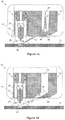
- FIG. 1a shows the welding apparatus 10 brought into an operational position close to the workpiece 12.
- the primary welding device 14 comprises a consumable electrode 20 that is advanced within a contact tube or tip 22.
- the welding apparatus 10 is positioned to bring the electrode 20 into alignment with a desired weld initiation point 24 on the workpiece 12.
- the contact tip 22 is supported within a concentric shroud or nozzle 26 that then directs a flow of shielding gas 28 toward the workpiece 12 as shown in Figure 1b .
- the flow of shielding gas 28 could, for example, emanate from holes 30 in the contact tube 22 as shown.
- the skilled reader will understand that the shielding gas 28 may be selected from a wide range of options depending upon the material(s) of the workpiece and the parameters of the weld.
- the secondary melting device 16 is activated as shown in Figure 1c .
- the secondary melting device 16 is a low-power LBW device that generates a laser beam 32 from a laser 34 and directs and focuses that beam 32 through optics 36 and an aperture 38 to impinge upon the workpiece 12 at the initiation point 24.
- the laser beam 32 emerges from the aperture 38 of the secondary melting device 16 on a path that intersects a longitudinal axis projecting toward the workpiece from the electrode 20.
- the laser beam 32 heats and locally melts the workpiece 12 around the initiation point 24 to form a weld pool 40.
- the shielding gas 28 surrounds and shields the weld pool 40 from ambient air.
- the temperature and other characteristics of the weld pool 40 are monitored by an infra-red weld pool sensor 42 that is conveniently supported by the welding apparatus 10 as shown.
- an infra-red weld pool sensor 42 that is conveniently supported by the welding apparatus 10 as shown.
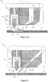
- the primary welding device 14 When the primary welding device 14 is activated as shown in Figure 1d , an arc 44 is established between the electrode 20 and the workpiece 12 via the weld pool 40. Thus, the primary welding device 14 initiates welding in the already-molten and homogeneous weld pool 40. This avoids or mitigates the discontinuities that bedevil weld initiation in prior art welding techniques.
- the shielding gas 28 flowing from the primary welding device 14 not only protects the weld pool 40 while the secondary melting device 16 is active but also surrounds the arc 44 to protect the weld itself.
- the same composition of shielding gas 28 could be used for both purposes, or the composition of the shielding gas 28 could be varied from one operation to the next. In any event it is advantageous for the shielding gas 28 to flow continuously and without interruption as the welding apparatus 10 switches from forming the weld pool 40 to forming the weld.
- the secondary melting device 16 is deactivated to turn off the laser 34.
- establishment of the arc 44 could be sensed as the trigger for deactivating the secondary melting device 16.
- establishment of the arc 44 could be triggered immediately upon deactivation of the secondary melting device 16. Either way, the arc 44 is established before the weld pool 40 cools significantly. Also, the aperture 38 is closed to protect the laser 34 and the optics 36 from electromagnetic radiation emitted from the arc 44.
- the aperture 38 is closed by a shutter 46 that is driven by a shutter drive mechanism 48 to slide across the aperture 38.
- the shutter 46 bears against a stop 50. Sliding or translational movement of the shutter 46 is convenient as shown. However, the shutter 46 could instead pivot relative to the welding apparatus 10 so as to close the aperture 38 by rotating about any suitable axis.
- the establishment and stability of the arc 44 may be determined by the weld pool sensor 42 and/or by monitoring fluctuations in current or voltage in the power supply of the primary welding device 14.
- welding can begin by effecting relative movement between the welding apparatus 10 and the workpiece 12 as shown in Figure 1e .
- the relative movement between the welding apparatus 10 and the workpiece 12 creates a weld 52 that incorporates the original weld pool 40, whose previous position is shown in Figure 1e in dashed lines.
- the original weld pool 40 becomes a substantially homogeneous part of the weld 52 itself.
- the weld 52 is formed from the advancing electrode 20 and the material of the workpiece 12, which melt together into a new weld pool 54 ahead of the weld 52.
- welding continues until the weld 52 is complete and the welding apparatus 10 reaches a termination point on the workpiece 12.
- the primary welding device 14 is then deactivated and the flow of shielding gas 28 is turned off.
- weld 52 it is possible for the weld 52 to return to the initiation point 24 and therefore to be endless, most commonly when forming a circumferential girth weld when fabricating a pipeline. In that event, there will be some re-welding at a termination point coinciding with the initiation point 24.
- FIG 2 shows a second embodiment of the invention in which like numerals are used for like features.
- the second embodiment is shown here at the same stage as shown in Figure 1c for the first embodiment, that is, with the flow of shielding gas 28 turned on and the weld pool 40 being formed in the workpiece 12 by the secondary melting device 16.
- the second embodiment shown in Figure 2 differs from the first embodiment shown in Figure 1 in that the laser 34 and optics 36 of the secondary melting device 16 are replaced by a plasma arc device 56 that directs an arc or jet of hot plasma 58 at the workpiece 12 through the aperture 38.
- the plasma 58 heats the workpiece 12 to form the weld pool 40.
- the plasma arc device 56 is deactivated, the shutter 46 is closed and the primary welding device 14 is activated to start a weld that incorporates the weld pool 40.
- FIGs 3a and 3b show a third embodiment of the invention in which, again, like numerals are used for like features.
- the third embodiment is shown here at the same stages as shown respectively in Figures 1c and 1d for the first embodiment.
- the stages shown in Figures 1a and 1b have already happened, so that the welding apparatus 10 has been positioned and the flow of shielding gas 28 has been turned on.
- Figure 3a the flow of shielding gas 28 is continuing and the weld pool 40 is being formed in the workpiece 12 by the secondary melting device 16 while the primary welding device 14 remains inactive.
- Figure 3b shows the primary welding device 14 activated, the secondary melting device 16 turned off and the shutter 46 closed.
- the third embodiment shown in Figures 3a and 3b differs from the first and second embodiments in that the secondary melting device 16 comprises a retractable tungsten rod 60 of a type used as a non-consumable electrode in GTAW or TIG operations.
- the rod 60 is movable telescopically along its longitudinal axis by a drive mechanism 64 within a friction-fitted sleeve 62 in the surrounding body of the secondary melting device 16.
- the rod 60 is extended by the drive mechanism 64 through the aperture 38 toward the initiation point 24 as shown in Figure 3a .
- a secondary arc 66 is established between the distal end of the rod 60 and the workpiece 12 to form a weld pool 40 as shown.
- the rod 60 is de-energised to extinguish the secondary arc 66 and is then quickly retracted by the drive mechanism 64 into the surrounding body of the secondary melting device 16.
- the shutter 46 is then closed and the primary welding device 14 is activated to start a weld that incorporates the weld pool 40. It may, however, be possible to activate the primary welding device 14 before retracting the rod 60.
- the rod 60 can retract very quickly, for example in less than 0.3 seconds, to allow the shutter 46 to be closed so that welding can begin before the weld pool 40 cools significantly.
- the drive mechanism 64 may extend the rod 60 against the bias of a mechanical spring or a gas spring and latch the extended rod 60 against that bias, so that the rod 60 snaps back into a retracted position upon being unlatched.
- a tungsten electrode used in GTAW requires particular shielding gases such as pure argon.
- shielding gases are not necessarily appropriate for forming the weld itself. Consequently, the composition of he shielding gas supplied through the primary welding device 14 could be changed as the welding apparatus 10 switches from forming the weld pool 40 to forming the weld.
- a shielding gas appropriate for a tungsten electrode could be supplied through the secondary melting device 16, or indeed along the tungsten rod 60, before a different shielding gas is supplied through the primary welding device 14 for forming the weld.
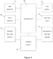
- this block diagram of the welding apparatus 10 shows how a controller 68 and power supply 70 interact with other aforementioned components and functions.
- the controller 68 takes input from the weld pool sensor 42 and an arc monitoring device 72 to control the primary welding device 14 and the secondary melting device 16 in addition to the shutter drive 48 and a shielding gas supply 74.
- the common power supply 70 conveniently provides electrical power to both the primary welding device 14 and the secondary melting device 16.
- the secondary melting device could be reactivated upon termination of a weld.
- the secondary melting device could improve the condition of all or part of the weld, such as a termination region of the weld.
Landscapes
- Engineering & Computer Science (AREA)
- Physics & Mathematics (AREA)
- Plasma & Fusion (AREA)
- Mechanical Engineering (AREA)
- Optics & Photonics (AREA)
- Arc Welding In General (AREA)
- Lining Or Joining Of Plastics Or The Like (AREA)
Claims (29)
- Verfahren zum Schweißen eines Werkstücks (12), das Folgendes umfasst:Aktivieren einer Schmelzvorrichtung (16), um ein geschmolzenes Schweißbad (40) in dem Werkstück (12) auszubilden;Deaktivieren der Schmelzvorrichtung (16);Aktivieren einer Schweißvorrichtung (14), um eine Schweißung (52) in dem Schweißbad (40) einzuleiten; undBewirken einer Relativbewegung zwischen der aktivierten Schweißvorrichtung (14) und dem Werkstück (12), um die eingeleitete Schweißung (52) fortzusetzen, während die Schmelzvorrichtung (16) deaktiviert ist;gekennzeichnet durch Schützen der deaktivierten Schmelzvorrichtung (16) vor Strahlungswärme, die durch die aktivierte Schweißvorrichtung (14) emittiert wird, durch Bewegen einer Barriere (46) in eine Sperrposition zwischen der deaktivierten Schmelzvorrichtung (16) und der aktivierten Schweißvorrichtung (14) als Reaktion auf die Deaktivierung der Schmelzvorrichtung (16);wobei die Schweißvorrichtung (14) und die Schmelzvorrichtung (16) während der Relativbewegung zwischen der aktivierten Schweißvorrichtung (14) und dem Werkstück (12) in einer festen Beziehung stehen.
- Verfahren nach Anspruch 1, das ein Abschließen der eingeleiteten Schweißung (52) umfasst, während die Schmelzvorrichtung (16) durchgehend deaktiviert ist.
- Verfahren nach Anspruch 1 oder 2, wobei die Schweißvorrichtung (14) und die Schmelzvorrichtung (16) beide durch einen Schweißwagen oder Roboter getragen werden, der relativ zu dem Werkstück (12) bewegt wird.
- Verfahren nach einem der vorhergehenden Ansprüche, das Folgendes umfasst:Richten eines Schutzgasstroms (28) auf das Werkstück (12); undAktivieren der Schmelzvorrichtung (16), um das Schweißbad (40) in einer durch den Schutzgasstrom (28) definierten Schutzatmosphäre auszubilden.
- Verfahren nach Anspruch 4, das das Einleiten und Fortsetzen der Schweißung (52) in einer Schutzatmosphäre umfasst, die durch einen kontinuierlichen Schutzgasstrom (28) definiert ist.
- Verfahren nach Anspruch 4 oder 5, das das Ausbilden des Schweißbades (40) in einer Schutzgasatmosphäre aus Schutzgas (28) umfasst, das aus der Schweißvorrichtung (14) strömt.
- Verfahren nach Anspruch 4, das das Ausbilden des Schweißbades (40) in einer Schutzatmosphäre aus Schutzgas umfasst, das aus der Schmelzvorrichtung (16) strömt.
- Verfahren nach einem der Ansprüche 4 bis 7, das das Einleiten und Fortsetzen der Schweißung (52) in einer Schutzatmosphäre umfasst, die im Wesentlichen die gleiche Zusammensetzung aufweist wie die Schutzatmosphäre, die bei dem Ausbilden des Schweißbades (40) verwendet wird.
- Verfahren nach einem der Ansprüche 4 bis 7, das das Einleiten und Fortsetzen der Schweißung (52) in einer Schutzatmosphäre umfasst, die eine im Wesentlichen andere Zusammensetzung aufweist als die Schutzatmosphäre, die bei dem Ausbilden des Schweißbades (40) verwendet wird.
- Verfahren nach einem der vorhergehenden Ansprüche, das Folgendes umfasst:Überwachen des Schweißbades (40); undAktivieren der Schweißvorrichtung (14) als Reaktion auf überwachte Eigenschaften des Schweißbades (40).
- Verfahren nach einem der vorhergehenden Ansprüche, das ein Aufbringen von Schweißwärme von der Schweißvorrichtung (14) auf das Werkstück (12) vor dem Deaktivieren der Schmelzvorrichtung (16) umfasst.
- Verfahren nach Anspruch 11, das Folgendes umfasst:Bestimmen der Aktivierung der Schweißvorrichtung (14); undDeaktivieren der Schmelzvorrichtung (16) als Reaktion auf die Aktivierung der Schweißvorrichtung (14).
- Verfahren nach einem der vorhergehenden Ansprüche, das Folgendes umfasst:Richten der Schmelzwärme entlang einer ersten Achse von der Schmelzvorrichtung (16) auf das Werkstück (12); undRichten der Schweißwärme entlang einer zweiten Achse von der Schweißvorrichtung (14) auf das Werkstück (12);wobei die erste und die zweite Achse konvergieren und das Schweißbad (40) kreuzen.
- Verfahren nach einem der vorhergehenden Ansprüche, wobei die Schweißvorrichtung (14) einzeln in der Lage ist, eine wirksame Schweißung (52) in dem Werkstück (12) herzustellen.
- Verfahren nach einem der vorhergehenden Ansprüche, wobei die Schmelzvorrichtung (16) einzeln nicht in der Lage ist, eine wirksame Schweißung (52) in dem Werkstück (12) herzustellen.
- Verfahren nach einem der vorhergehenden Ansprüche, wobei die Schweißvorrichtung (14) einen MSG-Brenner umfasst, der die Schweißung durch einen Schutzgaslichtbogen ausbildet.
- Verfahren nach einem der vorhergehenden Ansprüche, wobei die Schmelzvorrichtung (16) einen Laser oder einen Plasmabrenner umfasst.
- Verfahren nach einem der Ansprüche 1 bis 16, wobei die Schmelzvorrichtung (16) eine Wolframelektrode umfasst, die das Schweißbad durch einen Lichtbogen ausbildet.
- Verfahren nach Anspruch 18, wobei die Wolframelektrode bei Deaktivierung der Schmelzvorrichtung (16) zurückgezogen wird.
- Schweißeinrichtung (10), die Folgendes umfasst:eine Schmelzvorrichtung (16) zum Ausbilden eines Schweißbades (40) an einem Schweißeinleitungspunkt (24);eine Schweißvorrichtung (14) zum Ausbilden einer Schweißung (52), die an dem Schweißbad (40) eingeleitet werden soll;und gekennzeichnet durch Folgendes:eine Steuerung (68), die programmiert ist, um die Schmelzvorrichtung (16) zu deaktivieren und die Schweißvorrichtung (14) zu aktivieren, um die Schweißung (52) abzuschließen, wobei die Schmelzvorrichtung (16) deaktiviert bleibt;eine Barriere (46), die bei Deaktivierung der Schmelzvorrichtung (16) durch die Steuerung (68) in eine Sperrposition zwischen der deaktivierten Schmelzvorrichtung (16) und der aktivierten Schweißvorrichtung (14) bewegbar ist;wobei die Schweißvorrichtung (14) und die Schmelzvorrichtung (16) zusammen auf einer gemeinsamen Tragstruktur (18) für eine Bewegung relativ zu einem Werkstück (12) montiert sind.
- Einrichtung (10) nach Anspruch 20, wobei:die Schmelzvorrichtung (16) angeordnet ist, um Schmelzwärme entlang einer ersten Achse auf ein Werkstück (12) zu richten; unddie Schweißvorrichtung (14) angeordnet ist, um Schweißwärme entlang einer zweiten Achse, die mit der ersten Achse konvergiert, auf das Werkstück (12) zu richten.
- Einrichtung (10) nach Anspruch 21, wobei die Schweißvorrichtung (14) angeordnet ist, um einen Schutzgasstrom (28) auf das Werkstück (12) zu richten, um die erste Achse zu schneiden.
- Einrichtung (10) nach Anspruch 20 oder 21, wobei die Steuerung (68) auf einen Schweißbadsensor (42) reagiert, um die Schweißvorrichtung (14) als Reaktion auf überwachte Eigenschaften des Schweißbades (40) zu aktivieren.
- Einrichtung (10) nach einem der Ansprüche 20 bis 23, wobei die Steuerung (68) auf einen Aktivierungssensor (72) reagiert, um die Schmelzvorrichtung (16) als Reaktion auf die Aktivierung der Schweißvorrichtung (14) zu deaktivieren.
- Einrichtung (10) nach einem der Ansprüche 20 bis 24, wobei die Schweißvorrichtung (14) und die Schmelzvorrichtung (16) eine gemeinsame Stromversorgung (70) nutzen.
- Einrichtung (10) nach einem der Ansprüche 20 bis 25, wobei die Schweißvorrichtung (14) einen MSG-Brenner umfasst.
- Einrichtung (10) nach einem der Ansprüche 20 bis 26, wobei die Schmelzvorrichtung (16) einen Laser oder einen Plasmabrenner umfasst.
- Einrichtung (10) nach einem der Ansprüche 20 bis 27, wobei die Schmelzvorrichtung (16) eine Wolframelektrode umfasst.
- Einrichtung (10) nach Anspruch 28, wobei die Wolframelektrode bei Deaktivierung der Schmelzvorrichtung (16) zurückziehbar ist.
Applications Claiming Priority (2)
| Application Number | Priority Date | Filing Date | Title |
|---|---|---|---|
| GB1719991.0A GB2569110B (en) | 2017-11-30 | 2017-11-30 | Preheating Method and Apparatus for Welding |
| PCT/IB2018/001481 WO2019106430A2 (en) | 2017-11-30 | 2018-11-26 | Arc welding |
Publications (2)
| Publication Number | Publication Date |
|---|---|
| EP3717169A2 EP3717169A2 (de) | 2020-10-07 |
| EP3717169B1 true EP3717169B1 (de) | 2021-11-24 |
Family
ID=60950274
Family Applications (1)
| Application Number | Title | Priority Date | Filing Date |
|---|---|---|---|
| EP18842717.3A Active EP3717169B1 (de) | 2017-11-30 | 2018-11-26 | Verfahren zum schweissen mit schmelz- und schweissvorrichtungen und deaktivierung der schmelzvorrichtung; zugehörige schweisseinrichtung |
Country Status (5)
| Country | Link |
|---|---|
| US (1) | US11213918B2 (de) |
| EP (1) | EP3717169B1 (de) |
| AU (1) | AU2018374566B2 (de) |
| GB (1) | GB2569110B (de) |
| WO (1) | WO2019106430A2 (de) |
Families Citing this family (2)
| Publication number | Priority date | Publication date | Assignee | Title |
|---|---|---|---|---|
| CN110587079B (zh) * | 2019-10-24 | 2021-08-06 | 青岛磊金德冲压件有限公司 | 一种不锈钢与异种材料电弧焊接的方法 |
| WO2023183229A1 (en) * | 2022-03-21 | 2023-09-28 | The Esab Group Inc. | Arc stability determination based on nozzle voltage |
Family Cites Families (12)
| Publication number | Priority date | Publication date | Assignee | Title |
|---|---|---|---|---|
| JPS608916B2 (ja) * | 1982-10-06 | 1985-03-06 | 工業技術院長 | レ−ザとミグを併用した溶接法 |
| JP2892212B2 (ja) | 1992-04-20 | 1999-05-17 | 株式会社東芝 | エレベータ走行試験装置 |
| JP2001239368A (ja) | 2000-02-29 | 2001-09-04 | Babcock Hitachi Kk | アーク溶接装置及び方法並びにこれに用いる溶接トーチ |
| JP2002248571A (ja) | 2001-02-23 | 2002-09-03 | Daihen Corp | レーザ照射アークスタート制御方法 |
| EP1581359B1 (de) | 2002-11-12 | 2011-08-10 | Plasma Laser Technologies Ltd. | Plasma-metall-schutzgasschweissen |
| US6906281B2 (en) | 2003-03-03 | 2005-06-14 | Dana Corporation | Method for laser welding of metal |
| AT413667B (de) * | 2004-05-10 | 2006-04-15 | Fronius Int Gmbh | Schweissverfahren und laser-hybrid-schweissbrenner |
| FR2886562B1 (fr) | 2005-06-02 | 2008-12-19 | Serimer Dasa Soc Par Actions S | Procede de soudage, en particulier de pieces tubulaires telles que des conduits metalliques mis bout a bout pour former des canalisations metalliques du type pipeline |
| JP5294573B2 (ja) * | 2007-05-17 | 2013-09-18 | 日立Geニュークリア・エナジー株式会社 | レーザとアークの複合溶接装置及び方法 |
| EP2047940A1 (de) * | 2007-10-08 | 2009-04-15 | Siemens Aktiengesellschaft | Aufheiztemperatur während Schweißarbeiten |
| DE102012218931A1 (de) | 2012-10-17 | 2014-04-17 | Bayerische Motoren Werke Aktiengesellschaft | Metallschutzgasschweißverfahren |
| US10440784B2 (en) * | 2014-10-14 | 2019-10-08 | Illinois Tool Works Inc. | Reduced-distortion hybrid induction heating/welding assembly |
-
2017
- 2017-11-30 GB GB1719991.0A patent/GB2569110B/en active Active
-
2018
- 2018-11-26 US US16/768,623 patent/US11213918B2/en active Active
- 2018-11-26 WO PCT/IB2018/001481 patent/WO2019106430A2/en not_active Ceased
- 2018-11-26 EP EP18842717.3A patent/EP3717169B1/de active Active
- 2018-11-26 AU AU2018374566A patent/AU2018374566B2/en active Active
Also Published As
| Publication number | Publication date |
|---|---|
| WO2019106430A3 (en) | 2019-07-18 |
| BR112020009994A2 (pt) | 2020-11-03 |
| WO2019106430A2 (en) | 2019-06-06 |
| US20200376602A1 (en) | 2020-12-03 |
| AU2018374566B2 (en) | 2024-03-07 |
| EP3717169A2 (de) | 2020-10-07 |
| US11213918B2 (en) | 2022-01-04 |
| GB201719991D0 (en) | 2018-01-17 |
| AU2018374566A1 (en) | 2020-05-14 |
| GB2569110A (en) | 2019-06-12 |
| GB2569110B (en) | 2021-12-15 |
Similar Documents
| Publication | Publication Date | Title |
|---|---|---|
| EP2744619B1 (de) | Verfahren zum starten und verwendung einer kombination aus schweissdrahtversorgung und hoch intensiver energiequelle zum schweissen | |
| US10052707B2 (en) | Method and system to use AC welding waveform and enhanced consumable to improve welding of galvanized workpiece | |
| US9718147B2 (en) | Method and system to start and use combination filler wire feed and high intensity energy source for root pass welding of the inner diameter of clad pipe | |
| US9782850B2 (en) | Method and system to start and use combination filler wire feed and high intensity energy source for welding | |
| JP3198490U (ja) | 溶接のために溶接ワイヤ送りと強力エネルギ源との組合わせを始動させ且つ使用する方法及びシステム | |
| US9149885B2 (en) | Method and apparatus for the production of a welding seam or a three-dimensional structure on a surface of a metallic work piece | |
| US20040238511A1 (en) | Method and apparatus for initiating welding arc with aid of vaporized chemical | |
| US20130092667A1 (en) | Method and System to Start and Use Combination Filler Wire Feed and High Intensity Energy Source for Welding | |
| JPH11509477A (ja) | 強化されたレーザー光線溶接 | |
| WO2013050863A1 (en) | Apparatus for and method of post weld laser release of gas build up in a gmaw weld using a laser beam | |
| WO2014087227A1 (en) | Method and system to start and use combination filler wire feed and high intensity energy source for welding | |
| EP0998368B1 (de) | Plasma-lichtbogen-punktschweissen von fahrzeugkarosserie | |
| DK3107677T3 (en) | METHOD AND DEVICE FOR GAS SHIELDED METAL BOW WELDING WITH PROTECTIVE GAS USING A NON-MELTABLE WIRING ELECTRODE AND A MELTING ELECTRODE | |
| US11213918B2 (en) | Arc welding | |
| US12383972B2 (en) | Systems and methods to control a wire electrode at the end of a weld | |
| BR112020009994B1 (pt) | Método para soldar uma peça de trabalho e aparelho de soldagem | |
| JP2023112413A (ja) | アーク溶接方法及びアーク溶接装置 |
Legal Events
| Date | Code | Title | Description |
|---|---|---|---|
| STAA | Information on the status of an ep patent application or granted ep patent |
Free format text: STATUS: UNKNOWN |
|
| STAA | Information on the status of an ep patent application or granted ep patent |
Free format text: STATUS: THE INTERNATIONAL PUBLICATION HAS BEEN MADE |
|
| PUAI | Public reference made under article 153(3) epc to a published international application that has entered the european phase |
Free format text: ORIGINAL CODE: 0009012 |
|
| STAA | Information on the status of an ep patent application or granted ep patent |
Free format text: STATUS: REQUEST FOR EXAMINATION WAS MADE |
|
| 17P | Request for examination filed |
Effective date: 20200630 |
|
| AK | Designated contracting states |
Kind code of ref document: A2 Designated state(s): AL AT BE BG CH CY CZ DE DK EE ES FI FR GB GR HR HU IE IS IT LI LT LU LV MC MK MT NL NO PL PT RO RS SE SI SK SM TR |
|
| AX | Request for extension of the european patent |
Extension state: BA ME |
|
| DAV | Request for validation of the european patent (deleted) | ||
| DAX | Request for extension of the european patent (deleted) | ||
| GRAP | Despatch of communication of intention to grant a patent |
Free format text: ORIGINAL CODE: EPIDOSNIGR1 |
|
| STAA | Information on the status of an ep patent application or granted ep patent |
Free format text: STATUS: GRANT OF PATENT IS INTENDED |
|
| INTG | Intention to grant announced |
Effective date: 20210810 |
|
| GRAS | Grant fee paid |
Free format text: ORIGINAL CODE: EPIDOSNIGR3 |
|
| GRAA | (expected) grant |
Free format text: ORIGINAL CODE: 0009210 |
|
| STAA | Information on the status of an ep patent application or granted ep patent |
Free format text: STATUS: THE PATENT HAS BEEN GRANTED |
|
| AK | Designated contracting states |
Kind code of ref document: B1 Designated state(s): AL AT BE BG CH CY CZ DE DK EE ES FI FR GB GR HR HU IE IS IT LI LT LU LV MC MK MT NL NO PL PT RO RS SE SI SK SM TR |
|
| REG | Reference to a national code |
Ref country code: GB Ref legal event code: FG4D |
|
| REG | Reference to a national code |
Ref country code: DE Ref legal event code: R096 Ref document number: 602018027286 Country of ref document: DE |
|
| REG | Reference to a national code |
Ref country code: AT Ref legal event code: REF Ref document number: 1449477 Country of ref document: AT Kind code of ref document: T Effective date: 20211215 |
|
| REG | Reference to a national code |
Ref country code: IE Ref legal event code: FG4D |
|
| REG | Reference to a national code |
Ref country code: NL Ref legal event code: FP |
|
| REG | Reference to a national code |
Ref country code: LT Ref legal event code: MG9D |
|
| REG | Reference to a national code |
Ref country code: NO Ref legal event code: T2 Effective date: 20211124 |
|
| REG | Reference to a national code |
Ref country code: AT Ref legal event code: MK05 Ref document number: 1449477 Country of ref document: AT Kind code of ref document: T Effective date: 20211124 |
|
| PG25 | Lapsed in a contracting state [announced via postgrant information from national office to epo] |
Ref country code: RS Free format text: LAPSE BECAUSE OF FAILURE TO SUBMIT A TRANSLATION OF THE DESCRIPTION OR TO PAY THE FEE WITHIN THE PRESCRIBED TIME-LIMIT Effective date: 20211124 Ref country code: LT Free format text: LAPSE BECAUSE OF FAILURE TO SUBMIT A TRANSLATION OF THE DESCRIPTION OR TO PAY THE FEE WITHIN THE PRESCRIBED TIME-LIMIT Effective date: 20211124 Ref country code: FI Free format text: LAPSE BECAUSE OF FAILURE TO SUBMIT A TRANSLATION OF THE DESCRIPTION OR TO PAY THE FEE WITHIN THE PRESCRIBED TIME-LIMIT Effective date: 20211124 Ref country code: BG Free format text: LAPSE BECAUSE OF FAILURE TO SUBMIT A TRANSLATION OF THE DESCRIPTION OR TO PAY THE FEE WITHIN THE PRESCRIBED TIME-LIMIT Effective date: 20220224 Ref country code: AT Free format text: LAPSE BECAUSE OF FAILURE TO SUBMIT A TRANSLATION OF THE DESCRIPTION OR TO PAY THE FEE WITHIN THE PRESCRIBED TIME-LIMIT Effective date: 20211124 |
|
| PG25 | Lapsed in a contracting state [announced via postgrant information from national office to epo] |
Ref country code: IS Free format text: LAPSE BECAUSE OF FAILURE TO SUBMIT A TRANSLATION OF THE DESCRIPTION OR TO PAY THE FEE WITHIN THE PRESCRIBED TIME-LIMIT Effective date: 20220324 Ref country code: SE Free format text: LAPSE BECAUSE OF FAILURE TO SUBMIT A TRANSLATION OF THE DESCRIPTION OR TO PAY THE FEE WITHIN THE PRESCRIBED TIME-LIMIT Effective date: 20211124 Ref country code: PT Free format text: LAPSE BECAUSE OF FAILURE TO SUBMIT A TRANSLATION OF THE DESCRIPTION OR TO PAY THE FEE WITHIN THE PRESCRIBED TIME-LIMIT Effective date: 20220324 Ref country code: PL Free format text: LAPSE BECAUSE OF FAILURE TO SUBMIT A TRANSLATION OF THE DESCRIPTION OR TO PAY THE FEE WITHIN THE PRESCRIBED TIME-LIMIT Effective date: 20211124 Ref country code: LV Free format text: LAPSE BECAUSE OF FAILURE TO SUBMIT A TRANSLATION OF THE DESCRIPTION OR TO PAY THE FEE WITHIN THE PRESCRIBED TIME-LIMIT Effective date: 20211124 Ref country code: HR Free format text: LAPSE BECAUSE OF FAILURE TO SUBMIT A TRANSLATION OF THE DESCRIPTION OR TO PAY THE FEE WITHIN THE PRESCRIBED TIME-LIMIT Effective date: 20211124 Ref country code: GR Free format text: LAPSE BECAUSE OF FAILURE TO SUBMIT A TRANSLATION OF THE DESCRIPTION OR TO PAY THE FEE WITHIN THE PRESCRIBED TIME-LIMIT Effective date: 20220225 |
|
| REG | Reference to a national code |
Ref country code: CH Ref legal event code: PL |
|
| PG25 | Lapsed in a contracting state [announced via postgrant information from national office to epo] |
Ref country code: SM Free format text: LAPSE BECAUSE OF FAILURE TO SUBMIT A TRANSLATION OF THE DESCRIPTION OR TO PAY THE FEE WITHIN THE PRESCRIBED TIME-LIMIT Effective date: 20211124 Ref country code: SK Free format text: LAPSE BECAUSE OF FAILURE TO SUBMIT A TRANSLATION OF THE DESCRIPTION OR TO PAY THE FEE WITHIN THE PRESCRIBED TIME-LIMIT Effective date: 20211124 Ref country code: RO Free format text: LAPSE BECAUSE OF FAILURE TO SUBMIT A TRANSLATION OF THE DESCRIPTION OR TO PAY THE FEE WITHIN THE PRESCRIBED TIME-LIMIT Effective date: 20211124 Ref country code: LU Free format text: LAPSE BECAUSE OF NON-PAYMENT OF DUE FEES Effective date: 20211126 Ref country code: ES Free format text: LAPSE BECAUSE OF FAILURE TO SUBMIT A TRANSLATION OF THE DESCRIPTION OR TO PAY THE FEE WITHIN THE PRESCRIBED TIME-LIMIT Effective date: 20211124 Ref country code: EE Free format text: LAPSE BECAUSE OF FAILURE TO SUBMIT A TRANSLATION OF THE DESCRIPTION OR TO PAY THE FEE WITHIN THE PRESCRIBED TIME-LIMIT Effective date: 20211124 Ref country code: DK Free format text: LAPSE BECAUSE OF FAILURE TO SUBMIT A TRANSLATION OF THE DESCRIPTION OR TO PAY THE FEE WITHIN THE PRESCRIBED TIME-LIMIT Effective date: 20211124 Ref country code: CZ Free format text: LAPSE BECAUSE OF FAILURE TO SUBMIT A TRANSLATION OF THE DESCRIPTION OR TO PAY THE FEE WITHIN THE PRESCRIBED TIME-LIMIT Effective date: 20211124 Ref country code: BE Free format text: LAPSE BECAUSE OF NON-PAYMENT OF DUE FEES Effective date: 20211130 |
|
| REG | Reference to a national code |
Ref country code: BE Ref legal event code: MM Effective date: 20211130 |
|
| REG | Reference to a national code |
Ref country code: DE Ref legal event code: R097 Ref document number: 602018027286 Country of ref document: DE |
|
| PG25 | Lapsed in a contracting state [announced via postgrant information from national office to epo] |
Ref country code: MC Free format text: LAPSE BECAUSE OF FAILURE TO SUBMIT A TRANSLATION OF THE DESCRIPTION OR TO PAY THE FEE WITHIN THE PRESCRIBED TIME-LIMIT Effective date: 20211124 |
|
| PLBE | No opposition filed within time limit |
Free format text: ORIGINAL CODE: 0009261 |
|
| STAA | Information on the status of an ep patent application or granted ep patent |
Free format text: STATUS: NO OPPOSITION FILED WITHIN TIME LIMIT |
|
| PG25 | Lapsed in a contracting state [announced via postgrant information from national office to epo] |
Ref country code: IE Free format text: LAPSE BECAUSE OF NON-PAYMENT OF DUE FEES Effective date: 20211126 Ref country code: AL Free format text: LAPSE BECAUSE OF FAILURE TO SUBMIT A TRANSLATION OF THE DESCRIPTION OR TO PAY THE FEE WITHIN THE PRESCRIBED TIME-LIMIT Effective date: 20211124 |
|
| 26N | No opposition filed |
Effective date: 20220825 |
|
| PG25 | Lapsed in a contracting state [announced via postgrant information from national office to epo] |
Ref country code: SI Free format text: LAPSE BECAUSE OF FAILURE TO SUBMIT A TRANSLATION OF THE DESCRIPTION OR TO PAY THE FEE WITHIN THE PRESCRIBED TIME-LIMIT Effective date: 20211124 |
|
| PG25 | Lapsed in a contracting state [announced via postgrant information from national office to epo] |
Ref country code: IT Free format text: LAPSE BECAUSE OF FAILURE TO SUBMIT A TRANSLATION OF THE DESCRIPTION OR TO PAY THE FEE WITHIN THE PRESCRIBED TIME-LIMIT Effective date: 20211124 |
|
| PG25 | Lapsed in a contracting state [announced via postgrant information from national office to epo] |
Ref country code: CY Free format text: LAPSE BECAUSE OF FAILURE TO SUBMIT A TRANSLATION OF THE DESCRIPTION OR TO PAY THE FEE WITHIN THE PRESCRIBED TIME-LIMIT Effective date: 20211124 |
|
| PG25 | Lapsed in a contracting state [announced via postgrant information from national office to epo] |
Ref country code: LI Free format text: LAPSE BECAUSE OF NON-PAYMENT OF DUE FEES Effective date: 20220701 Ref country code: HU Free format text: LAPSE BECAUSE OF FAILURE TO SUBMIT A TRANSLATION OF THE DESCRIPTION OR TO PAY THE FEE WITHIN THE PRESCRIBED TIME-LIMIT; INVALID AB INITIO Effective date: 20181126 Ref country code: CH Free format text: LAPSE BECAUSE OF NON-PAYMENT OF DUE FEES Effective date: 20220701 |
|
| PG25 | Lapsed in a contracting state [announced via postgrant information from national office to epo] |
Ref country code: MK Free format text: LAPSE BECAUSE OF FAILURE TO SUBMIT A TRANSLATION OF THE DESCRIPTION OR TO PAY THE FEE WITHIN THE PRESCRIBED TIME-LIMIT Effective date: 20211124 |
|
| PG25 | Lapsed in a contracting state [announced via postgrant information from national office to epo] |
Ref country code: MT Free format text: LAPSE BECAUSE OF FAILURE TO SUBMIT A TRANSLATION OF THE DESCRIPTION OR TO PAY THE FEE WITHIN THE PRESCRIBED TIME-LIMIT Effective date: 20211124 |
|
| P01 | Opt-out of the competence of the unified patent court (upc) registered |
Free format text: CASE NUMBER: UPC_APP_1736_3717169/2025 Effective date: 20250731 |
|
| PG25 | Lapsed in a contracting state [announced via postgrant information from national office to epo] |
Ref country code: TR Free format text: LAPSE BECAUSE OF FAILURE TO SUBMIT A TRANSLATION OF THE DESCRIPTION OR TO PAY THE FEE WITHIN THE PRESCRIBED TIME-LIMIT Effective date: 20211124 |
|
| PGFP | Annual fee paid to national office [announced via postgrant information from national office to epo] |
Ref country code: NL Payment date: 20251119 Year of fee payment: 8 |
|
| PGFP | Annual fee paid to national office [announced via postgrant information from national office to epo] |
Ref country code: DE Payment date: 20251118 Year of fee payment: 8 |
|
| PGFP | Annual fee paid to national office [announced via postgrant information from national office to epo] |
Ref country code: GB Payment date: 20251126 Year of fee payment: 8 |
|
| PGFP | Annual fee paid to national office [announced via postgrant information from national office to epo] |
Ref country code: NO Payment date: 20251118 Year of fee payment: 8 |
|
| PGFP | Annual fee paid to national office [announced via postgrant information from national office to epo] |
Ref country code: FR Payment date: 20251120 Year of fee payment: 8 |
|
| REG | Reference to a national code |
Ref country code: DE Ref legal event code: R081 Ref document number: 602018027286 Country of ref document: DE Owner name: ACERGY FRANCE SAS, FR Free format text: FORMER OWNER: ACERGY FRANCE SAS, SURESNES, FR |