EP3717432B1 - Kraftfahrzeugverglasung für aussenlichtsignalisierung, fahrzeug damit und ihre herstellung - Google Patents
Kraftfahrzeugverglasung für aussenlichtsignalisierung, fahrzeug damit und ihre herstellung Download PDFInfo
- Publication number
- EP3717432B1 EP3717432B1 EP18827194.4A EP18827194A EP3717432B1 EP 3717432 B1 EP3717432 B1 EP 3717432B1 EP 18827194 A EP18827194 A EP 18827194A EP 3717432 B1 EP3717432 B1 EP 3717432B1
- Authority
- EP
- European Patent Office
- Prior art keywords
- face
- optic
- glazing
- redirection
- film
- Prior art date
- Legal status (The legal status is an assumption and is not a legal conclusion. Google has not performed a legal analysis and makes no representation as to the accuracy of the status listed.)
- Active
Links
Images


Classifications
-
- B—PERFORMING OPERATIONS; TRANSPORTING
- B60—VEHICLES IN GENERAL
- B60Q—ARRANGEMENT OF SIGNALLING OR LIGHTING DEVICES, THE MOUNTING OR SUPPORTING THEREOF OR CIRCUITS THEREFOR, FOR VEHICLES IN GENERAL
- B60Q1/00—Arrangement of optical signalling or lighting devices, the mounting or supporting thereof or circuits therefor
- B60Q1/26—Arrangement of optical signalling or lighting devices, the mounting or supporting thereof or circuits therefor the devices being primarily intended to indicate the vehicle, or parts thereof, or to give signals, to other traffic
- B60Q1/2661—Arrangement of optical signalling or lighting devices, the mounting or supporting thereof or circuits therefor the devices being primarily intended to indicate the vehicle, or parts thereof, or to give signals, to other traffic mounted on parts having other functions
- B60Q1/268—Arrangement of optical signalling or lighting devices, the mounting or supporting thereof or circuits therefor the devices being primarily intended to indicate the vehicle, or parts thereof, or to give signals, to other traffic mounted on parts having other functions on windscreens or windows
-
- C—CHEMISTRY; METALLURGY
- C03—GLASS; MINERAL OR SLAG WOOL
- C03C—CHEMICAL COMPOSITION OF GLASSES, GLAZES OR VITREOUS ENAMELS; SURFACE TREATMENT OF GLASS; SURFACE TREATMENT OF FIBRES OR FILAMENTS MADE FROM GLASS, MINERALS OR SLAGS; JOINING GLASS TO GLASS OR OTHER MATERIALS
- C03C17/00—Surface treatment of glass, not in the form of fibres or filaments, by coating
-
- B—PERFORMING OPERATIONS; TRANSPORTING
- B32—LAYERED PRODUCTS
- B32B—LAYERED PRODUCTS, i.e. PRODUCTS BUILT-UP OF STRATA OF FLAT OR NON-FLAT, e.g. CELLULAR OR HONEYCOMB, FORM
- B32B17/00—Layered products essentially comprising sheet glass, or glass, slag, or like fibres
- B32B17/06—Layered products essentially comprising sheet glass, or glass, slag, or like fibres comprising glass as the main or only constituent of a layer, next to another layer of a specific material
- B32B17/10—Layered products essentially comprising sheet glass, or glass, slag, or like fibres comprising glass as the main or only constituent of a layer, next to another layer of a specific material of synthetic resin
- B32B17/10005—Layered products essentially comprising sheet glass, or glass, slag, or like fibres comprising glass as the main or only constituent of a layer, next to another layer of a specific material of synthetic resin laminated safety glass or glazing
- B32B17/10009—Layered products essentially comprising sheet glass, or glass, slag, or like fibres comprising glass as the main or only constituent of a layer, next to another layer of a specific material of synthetic resin laminated safety glass or glazing characterized by the number, the constitution or treatment of glass sheets
- B32B17/10036—Layered products essentially comprising sheet glass, or glass, slag, or like fibres comprising glass as the main or only constituent of a layer, next to another layer of a specific material of synthetic resin laminated safety glass or glazing characterized by the number, the constitution or treatment of glass sheets comprising two outer glass sheets
-
- B—PERFORMING OPERATIONS; TRANSPORTING
- B32—LAYERED PRODUCTS
- B32B—LAYERED PRODUCTS, i.e. PRODUCTS BUILT-UP OF STRATA OF FLAT OR NON-FLAT, e.g. CELLULAR OR HONEYCOMB, FORM
- B32B17/00—Layered products essentially comprising sheet glass, or glass, slag, or like fibres
- B32B17/06—Layered products essentially comprising sheet glass, or glass, slag, or like fibres comprising glass as the main or only constituent of a layer, next to another layer of a specific material
- B32B17/10—Layered products essentially comprising sheet glass, or glass, slag, or like fibres comprising glass as the main or only constituent of a layer, next to another layer of a specific material of synthetic resin
- B32B17/10005—Layered products essentially comprising sheet glass, or glass, slag, or like fibres comprising glass as the main or only constituent of a layer, next to another layer of a specific material of synthetic resin laminated safety glass or glazing
- B32B17/10165—Functional features of the laminated safety glass or glazing
- B32B17/10293—Edge features, e.g. inserts or holes
-
- B—PERFORMING OPERATIONS; TRANSPORTING
- B32—LAYERED PRODUCTS
- B32B—LAYERED PRODUCTS, i.e. PRODUCTS BUILT-UP OF STRATA OF FLAT OR NON-FLAT, e.g. CELLULAR OR HONEYCOMB, FORM
- B32B17/00—Layered products essentially comprising sheet glass, or glass, slag, or like fibres
- B32B17/06—Layered products essentially comprising sheet glass, or glass, slag, or like fibres comprising glass as the main or only constituent of a layer, next to another layer of a specific material
- B32B17/10—Layered products essentially comprising sheet glass, or glass, slag, or like fibres comprising glass as the main or only constituent of a layer, next to another layer of a specific material of synthetic resin
- B32B17/10005—Layered products essentially comprising sheet glass, or glass, slag, or like fibres comprising glass as the main or only constituent of a layer, next to another layer of a specific material of synthetic resin laminated safety glass or glazing
- B32B17/10165—Functional features of the laminated safety glass or glazing
- B32B17/10541—Functional features of the laminated safety glass or glazing comprising a light source or a light guide
-
- B—PERFORMING OPERATIONS; TRANSPORTING
- B32—LAYERED PRODUCTS
- B32B—LAYERED PRODUCTS, i.e. PRODUCTS BUILT-UP OF STRATA OF FLAT OR NON-FLAT, e.g. CELLULAR OR HONEYCOMB, FORM
- B32B17/00—Layered products essentially comprising sheet glass, or glass, slag, or like fibres
- B32B17/06—Layered products essentially comprising sheet glass, or glass, slag, or like fibres comprising glass as the main or only constituent of a layer, next to another layer of a specific material
- B32B17/10—Layered products essentially comprising sheet glass, or glass, slag, or like fibres comprising glass as the main or only constituent of a layer, next to another layer of a specific material of synthetic resin
- B32B17/10005—Layered products essentially comprising sheet glass, or glass, slag, or like fibres comprising glass as the main or only constituent of a layer, next to another layer of a specific material of synthetic resin laminated safety glass or glazing
- B32B17/1055—Layered products essentially comprising sheet glass, or glass, slag, or like fibres comprising glass as the main or only constituent of a layer, next to another layer of a specific material of synthetic resin laminated safety glass or glazing characterized by the resin layer, i.e. interlayer
- B32B17/10761—Layered products essentially comprising sheet glass, or glass, slag, or like fibres comprising glass as the main or only constituent of a layer, next to another layer of a specific material of synthetic resin laminated safety glass or glazing characterized by the resin layer, i.e. interlayer containing vinyl acetal
-
- B—PERFORMING OPERATIONS; TRANSPORTING
- B32—LAYERED PRODUCTS
- B32B—LAYERED PRODUCTS, i.e. PRODUCTS BUILT-UP OF STRATA OF FLAT OR NON-FLAT, e.g. CELLULAR OR HONEYCOMB, FORM
- B32B17/00—Layered products essentially comprising sheet glass, or glass, slag, or like fibres
- B32B17/06—Layered products essentially comprising sheet glass, or glass, slag, or like fibres comprising glass as the main or only constituent of a layer, next to another layer of a specific material
- B32B17/10—Layered products essentially comprising sheet glass, or glass, slag, or like fibres comprising glass as the main or only constituent of a layer, next to another layer of a specific material of synthetic resin
- B32B17/10005—Layered products essentially comprising sheet glass, or glass, slag, or like fibres comprising glass as the main or only constituent of a layer, next to another layer of a specific material of synthetic resin laminated safety glass or glazing
- B32B17/1055—Layered products essentially comprising sheet glass, or glass, slag, or like fibres comprising glass as the main or only constituent of a layer, next to another layer of a specific material of synthetic resin laminated safety glass or glazing characterized by the resin layer, i.e. interlayer
- B32B17/1077—Layered products essentially comprising sheet glass, or glass, slag, or like fibres comprising glass as the main or only constituent of a layer, next to another layer of a specific material of synthetic resin laminated safety glass or glazing characterized by the resin layer, i.e. interlayer containing polyurethane
-
- B—PERFORMING OPERATIONS; TRANSPORTING
- B32—LAYERED PRODUCTS
- B32B—LAYERED PRODUCTS, i.e. PRODUCTS BUILT-UP OF STRATA OF FLAT OR NON-FLAT, e.g. CELLULAR OR HONEYCOMB, FORM
- B32B17/00—Layered products essentially comprising sheet glass, or glass, slag, or like fibres
- B32B17/06—Layered products essentially comprising sheet glass, or glass, slag, or like fibres comprising glass as the main or only constituent of a layer, next to another layer of a specific material
- B32B17/10—Layered products essentially comprising sheet glass, or glass, slag, or like fibres comprising glass as the main or only constituent of a layer, next to another layer of a specific material of synthetic resin
- B32B17/10005—Layered products essentially comprising sheet glass, or glass, slag, or like fibres comprising glass as the main or only constituent of a layer, next to another layer of a specific material of synthetic resin laminated safety glass or glazing
- B32B17/1055—Layered products essentially comprising sheet glass, or glass, slag, or like fibres comprising glass as the main or only constituent of a layer, next to another layer of a specific material of synthetic resin laminated safety glass or glazing characterized by the resin layer, i.e. interlayer
- B32B17/10779—Layered products essentially comprising sheet glass, or glass, slag, or like fibres comprising glass as the main or only constituent of a layer, next to another layer of a specific material of synthetic resin laminated safety glass or glazing characterized by the resin layer, i.e. interlayer containing polyester
-
- B—PERFORMING OPERATIONS; TRANSPORTING
- B32—LAYERED PRODUCTS
- B32B—LAYERED PRODUCTS, i.e. PRODUCTS BUILT-UP OF STRATA OF FLAT OR NON-FLAT, e.g. CELLULAR OR HONEYCOMB, FORM
- B32B17/00—Layered products essentially comprising sheet glass, or glass, slag, or like fibres
- B32B17/06—Layered products essentially comprising sheet glass, or glass, slag, or like fibres comprising glass as the main or only constituent of a layer, next to another layer of a specific material
- B32B17/10—Layered products essentially comprising sheet glass, or glass, slag, or like fibres comprising glass as the main or only constituent of a layer, next to another layer of a specific material of synthetic resin
- B32B17/10005—Layered products essentially comprising sheet glass, or glass, slag, or like fibres comprising glass as the main or only constituent of a layer, next to another layer of a specific material of synthetic resin laminated safety glass or glazing
- B32B17/1055—Layered products essentially comprising sheet glass, or glass, slag, or like fibres comprising glass as the main or only constituent of a layer, next to another layer of a specific material of synthetic resin laminated safety glass or glazing characterized by the resin layer, i.e. interlayer
- B32B17/10788—Layered products essentially comprising sheet glass, or glass, slag, or like fibres comprising glass as the main or only constituent of a layer, next to another layer of a specific material of synthetic resin laminated safety glass or glazing characterized by the resin layer, i.e. interlayer containing ethylene vinylacetate
-
- B—PERFORMING OPERATIONS; TRANSPORTING
- B32—LAYERED PRODUCTS
- B32B—LAYERED PRODUCTS, i.e. PRODUCTS BUILT-UP OF STRATA OF FLAT OR NON-FLAT, e.g. CELLULAR OR HONEYCOMB, FORM
- B32B3/00—Layered products comprising a layer with external or internal discontinuities or unevennesses, or a layer of non-planar shape; Layered products comprising a layer having particular features of form
- B32B3/26—Layered products comprising a layer with external or internal discontinuities or unevennesses, or a layer of non-planar shape; Layered products comprising a layer having particular features of form characterised by a particular shape of the outline of the cross-section of a continuous layer; characterised by a layer with cavities or internal voids ; characterised by an apertured layer
- B32B3/263—Layered products comprising a layer with external or internal discontinuities or unevennesses, or a layer of non-planar shape; Layered products comprising a layer having particular features of form characterised by a particular shape of the outline of the cross-section of a continuous layer; characterised by a layer with cavities or internal voids ; characterised by an apertured layer characterised by a layer having non-uniform thickness
-
- B—PERFORMING OPERATIONS; TRANSPORTING
- B32—LAYERED PRODUCTS
- B32B—LAYERED PRODUCTS, i.e. PRODUCTS BUILT-UP OF STRATA OF FLAT OR NON-FLAT, e.g. CELLULAR OR HONEYCOMB, FORM
- B32B3/00—Layered products comprising a layer with external or internal discontinuities or unevennesses, or a layer of non-planar shape; Layered products comprising a layer having particular features of form
- B32B3/26—Layered products comprising a layer with external or internal discontinuities or unevennesses, or a layer of non-planar shape; Layered products comprising a layer having particular features of form characterised by a particular shape of the outline of the cross-section of a continuous layer; characterised by a layer with cavities or internal voids ; characterised by an apertured layer
- B32B3/30—Layered products comprising a layer with external or internal discontinuities or unevennesses, or a layer of non-planar shape; Layered products comprising a layer having particular features of form characterised by a particular shape of the outline of the cross-section of a continuous layer; characterised by a layer with cavities or internal voids ; characterised by an apertured layer characterised by a layer formed with recesses or projections, e.g. hollows, grooves, protuberances, ribs
-
- B—PERFORMING OPERATIONS; TRANSPORTING
- B32—LAYERED PRODUCTS
- B32B—LAYERED PRODUCTS, i.e. PRODUCTS BUILT-UP OF STRATA OF FLAT OR NON-FLAT, e.g. CELLULAR OR HONEYCOMB, FORM
- B32B37/00—Methods or apparatus for laminating, e.g. by curing or by ultrasonic bonding
- B32B37/02—Methods or apparatus for laminating, e.g. by curing or by ultrasonic bonding characterised by a sequence of laminating steps, e.g. by adding new layers at consecutive laminating stations
-
- B—PERFORMING OPERATIONS; TRANSPORTING
- B60—VEHICLES IN GENERAL
- B60Q—ARRANGEMENT OF SIGNALLING OR LIGHTING DEVICES, THE MOUNTING OR SUPPORTING THEREOF OR CIRCUITS THEREFOR, FOR VEHICLES IN GENERAL
- B60Q1/00—Arrangement of optical signalling or lighting devices, the mounting or supporting thereof or circuits therefor
- B60Q1/26—Arrangement of optical signalling or lighting devices, the mounting or supporting thereof or circuits therefor the devices being primarily intended to indicate the vehicle, or parts thereof, or to give signals, to other traffic
- B60Q1/2696—Mounting of devices using LEDs
-
- F—MECHANICAL ENGINEERING; LIGHTING; HEATING; WEAPONS; BLASTING
- F21—LIGHTING
- F21S—NON-PORTABLE LIGHTING DEVICES; SYSTEMS THEREOF; VEHICLE LIGHTING DEVICES SPECIALLY ADAPTED FOR VEHICLE EXTERIORS
- F21S43/00—Signalling devices specially adapted for vehicle exteriors, e.g. brake lamps, direction indicator lights or reversing lights
- F21S43/20—Signalling devices specially adapted for vehicle exteriors, e.g. brake lamps, direction indicator lights or reversing lights characterised by refractors, transparent cover plates, light guides or filters
- F21S43/2605—Refractors
-
- G—PHYSICS
- G02—OPTICS
- G02B—OPTICAL ELEMENTS, SYSTEMS OR APPARATUS
- G02B27/00—Optical systems or apparatus not provided for by any of the groups G02B1/00 - G02B26/00, G02B30/00
-
- G—PHYSICS
- G02—OPTICS
- G02B—OPTICAL ELEMENTS, SYSTEMS OR APPARATUS
- G02B27/00—Optical systems or apparatus not provided for by any of the groups G02B1/00 - G02B26/00, G02B30/00
- G02B27/30—Collimators
-
- G—PHYSICS
- G02—OPTICS
- G02B—OPTICAL ELEMENTS, SYSTEMS OR APPARATUS
- G02B5/00—Optical elements other than lenses
- G02B5/04—Prisms
- G02B5/045—Prism arrays
-
- B—PERFORMING OPERATIONS; TRANSPORTING
- B60—VEHICLES IN GENERAL
- B60Q—ARRANGEMENT OF SIGNALLING OR LIGHTING DEVICES, THE MOUNTING OR SUPPORTING THEREOF OR CIRCUITS THEREFOR, FOR VEHICLES IN GENERAL
- B60Q1/00—Arrangement of optical signalling or lighting devices, the mounting or supporting thereof or circuits therefor
- B60Q1/26—Arrangement of optical signalling or lighting devices, the mounting or supporting thereof or circuits therefor the devices being primarily intended to indicate the vehicle, or parts thereof, or to give signals, to other traffic
- B60Q1/30—Arrangement of optical signalling or lighting devices, the mounting or supporting thereof or circuits therefor the devices being primarily intended to indicate the vehicle, or parts thereof, or to give signals, to other traffic for indicating rear of vehicle, e.g. by means of reflecting surfaces
- B60Q1/302—Arrangement of optical signalling or lighting devices, the mounting or supporting thereof or circuits therefor the devices being primarily intended to indicate the vehicle, or parts thereof, or to give signals, to other traffic for indicating rear of vehicle, e.g. by means of reflecting surfaces mounted in the vicinity, e.g. in the middle, of a rear window
-
- B—PERFORMING OPERATIONS; TRANSPORTING
- B60—VEHICLES IN GENERAL
- B60Q—ARRANGEMENT OF SIGNALLING OR LIGHTING DEVICES, THE MOUNTING OR SUPPORTING THEREOF OR CIRCUITS THEREFOR, FOR VEHICLES IN GENERAL
- B60Q1/00—Arrangement of optical signalling or lighting devices, the mounting or supporting thereof or circuits therefor
- B60Q1/26—Arrangement of optical signalling or lighting devices, the mounting or supporting thereof or circuits therefor the devices being primarily intended to indicate the vehicle, or parts thereof, or to give signals, to other traffic
- B60Q1/34—Arrangement of optical signalling or lighting devices, the mounting or supporting thereof or circuits therefor the devices being primarily intended to indicate the vehicle, or parts thereof, or to give signals, to other traffic for indicating change of drive direction
- B60Q1/38—Arrangement of optical signalling or lighting devices, the mounting or supporting thereof or circuits therefor the devices being primarily intended to indicate the vehicle, or parts thereof, or to give signals, to other traffic for indicating change of drive direction using immovably-mounted light sources, e.g. fixed flashing lamps
-
- B—PERFORMING OPERATIONS; TRANSPORTING
- B60—VEHICLES IN GENERAL
- B60Q—ARRANGEMENT OF SIGNALLING OR LIGHTING DEVICES, THE MOUNTING OR SUPPORTING THEREOF OR CIRCUITS THEREFOR, FOR VEHICLES IN GENERAL
- B60Q1/00—Arrangement of optical signalling or lighting devices, the mounting or supporting thereof or circuits therefor
- B60Q1/26—Arrangement of optical signalling or lighting devices, the mounting or supporting thereof or circuits therefor the devices being primarily intended to indicate the vehicle, or parts thereof, or to give signals, to other traffic
- B60Q1/50—Arrangement of optical signalling or lighting devices, the mounting or supporting thereof or circuits therefor the devices being primarily intended to indicate the vehicle, or parts thereof, or to give signals, to other traffic for indicating other intentions or conditions, e.g. request for waiting or overtaking
- B60Q1/52—Arrangement of optical signalling or lighting devices, the mounting or supporting thereof or circuits therefor the devices being primarily intended to indicate the vehicle, or parts thereof, or to give signals, to other traffic for indicating other intentions or conditions, e.g. request for waiting or overtaking for indicating emergencies
-
- B—PERFORMING OPERATIONS; TRANSPORTING
- B60—VEHICLES IN GENERAL
- B60Q—ARRANGEMENT OF SIGNALLING OR LIGHTING DEVICES, THE MOUNTING OR SUPPORTING THEREOF OR CIRCUITS THEREFOR, FOR VEHICLES IN GENERAL
- B60Q2400/00—Special features or arrangements of exterior signal lamps for vehicles
- B60Q2400/10—Electro- or photo- luminescent surfaces, e.g. signalling by way of electroluminescent strips or panels
-
- C—CHEMISTRY; METALLURGY
- C03—GLASS; MINERAL OR SLAG WOOL
- C03C—CHEMICAL COMPOSITION OF GLASSES, GLAZES OR VITREOUS ENAMELS; SURFACE TREATMENT OF GLASS; SURFACE TREATMENT OF FIBRES OR FILAMENTS MADE FROM GLASS, MINERALS OR SLAGS; JOINING GLASS TO GLASS OR OTHER MATERIALS
- C03C2217/00—Coatings on glass
- C03C2217/70—Properties of coatings
- C03C2217/77—Coatings having a rough surface
-
- F—MECHANICAL ENGINEERING; LIGHTING; HEATING; WEAPONS; BLASTING
- F21—LIGHTING
- F21S—NON-PORTABLE LIGHTING DEVICES; SYSTEMS THEREOF; VEHICLE LIGHTING DEVICES SPECIALLY ADAPTED FOR VEHICLE EXTERIORS
- F21S43/00—Signalling devices specially adapted for vehicle exteriors, e.g. brake lamps, direction indicator lights or reversing lights
- F21S43/10—Signalling devices specially adapted for vehicle exteriors, e.g. brake lamps, direction indicator lights or reversing lights characterised by the light source
- F21S43/13—Signalling devices specially adapted for vehicle exteriors, e.g. brake lamps, direction indicator lights or reversing lights characterised by the light source characterised by the type of light source
- F21S43/14—Light emitting diodes [LED]
- F21S43/145—Surface emitters, e.g. organic light emitting diodes [OLED]
-
- F—MECHANICAL ENGINEERING; LIGHTING; HEATING; WEAPONS; BLASTING
- F21—LIGHTING
- F21Y—INDEXING SCHEME ASSOCIATED WITH SUBCLASSES F21K, F21L, F21S and F21V, RELATING TO THE FORM OR THE KIND OF THE LIGHT SOURCES OR OF THE COLOUR OF THE LIGHT EMITTED
- F21Y2115/00—Light-generating elements of semiconductor light sources
- F21Y2115/10—Light-emitting diodes [LED]
- F21Y2115/15—Organic light-emitting diodes [OLED]
Definitions
- the invention relates to a vehicle glazing with external light signaling as well as a vehicle comprising such glazing and the manufacture of such glazing.
- the integration can be improved as well as the manufacturing process.
- the glazing comprises facing said light-emitting element, between face F2 and said light-emitting element, collimation optics, having a rear face on the exit surface side and a so-called collimation front face opposite the rear face.
- the collimating optics made of transparent material, preferably plastic (in particular thermoplastic, poly(ethylene terephthalate) PET, poly(ethylene naphthalate) PEN, polyethylene PE, poly(methyl methacrylate) PMMA, polydimethylsiloxane PDMS polyamide, polyimide, polyacrylate , polyester, polycarbonate, polysulfones, polyethersulfones, thermoplastic polyurethane) and/or even flexible, is preferably of (total) thickness E1 submillimeter, better still at most 0.6 mm or 0.3 mm or 0.15 mm.
- plastic in particular thermoplastic, poly(ethylene terephthalate) PET, poly(ethylene naphthalate) PEN, polyethylene PE, poly(methyl methacrylate) PMMA, polydimethylsiloxane PDMS polyamide, polyimide, polyacrylate , polyester, polycarbonate, polysulfones, polyethersulfones, thermoplastic polyurethane
- the collimation optic comprises, and even is, an optical film, preferably plastic (in particular thermoplastic, PET, PE, PC, PMMA, PDMS), in particular a film partially textured in its thickness, or as an alternative composite film comprising a transparent support ( plastic in particular as mentioned above) smooth with a transparent overlayer textured partially or entirely in thickness) or a set of preferably plastic optical films (in particular as mentioned above), each comprising a network of patterns with vertices S and with a pitch T between vertices which is from 10 ⁇ m to 500 ⁇ m preferably, with preferably at least 4 or even 10 patterns opposite the exit (or light-emitting) surface.
- plastic in particular thermoplastic, PET, PE, PC, PMMA, PDMS
- a film partially textured in its thickness or as an alternative composite film comprising a transparent support (plastic in particular as mentioned above) smooth with a transparent overlayer textured partially or entirely in thickness) or a set of preferably plastic optical films (in particular as mentioned above), each comprising a network of
- each prism being defined by two longitudinal faces, the prism preferably having a length L and a width W with L>2W and better still L>5W or L>10W.
- valleys - pointed or rounded - are defined with the same tolerances on the angle in the valley as the angle at the top already described and on the possible radius of curvature in the valley.
- each asymmetrical prism being defined by first and second longitudinal faces, the prism preferably having a length L and a width W with L>2W and better still L>5W or L>10W.
- Each asymmetrical prism has an apex angle a'0 ranging from 50 to 60° better 55° ⁇ 5°, 55° ⁇ 2° ° and the first longitudinal face (known as the long side) forms with the plane of the asymmetrical optical film a first angle a3, ranging from 31 to 41° better than 35° ⁇ 5°, 35° ⁇ 2°.
- the second longitudinal face (known as the short side) preferably forms with the plane of the asymmetric optical film a second angle a4, ranging from 79 to 99° or 90°, better from 85 to 90°, from 88 to 90°, preferably d at most 90°.
- the difference a4-a3 is greater than 40° and even 50°.
- valleys - pointed or rounded - are defined with the same tolerances on the angle in the valley as the angle at the top already described and on the possible radius of curvature in the valley.
- the normal to the large side directed towards face F2 is oriented towards the top of the rear window or the windscreen or towards the front of the side window.
- the glazing comprises, opposite the exit surface, a holographic redirection optic, in particular made of transparent material, preferably plastic, in particular thermoplastic (preferably polyester , poly(ethylene terephthalate) PET, polyethylene PE polycarbonate PC, poly(methyl methacrylate) PMMA, polystyrene, polyamide, polydimethylsiloxane PDMS, poly(ethylene naphthalate) PEN, polyimide, polyacrylate, polysulfone, polyethersulfone, (thermoplastic) polyurethane ), preferably on the exit surface (fixed at the periphery, for example glued or even welded or spaced apart by at most 1 mm), the holographic redirection optic comprises a front face towards the face F2 and an opposite rear face, the holographic redirection optics, comprises, better, a notably plastic film with a network of holographic patterns (one-dimensional, for example prismatic)
- air is between the exit surface and the entrance face of the holographic redirection optic
- air is between the holographic patterns of the final front face of the holographic redirection optics
- the front face of the holographic redirection film is spaced apart or in physical contact with a distinct transparent element of preferably subcentimetric thickness (protective and/or functional film, a second glazing if laminated glazing, face F4) and even at most 0.3mm, 0.15mm or corresponding to the first glazing.
- any material, even transparent, is avoided (glue, lamination insert) between the patterns of each film and in particular an air gap is created between the exit surface and the entry face of the first optical film.
- the (even each) peripheral attachment is preferably entirely outside (offset, therefore peripheral) of the light-emitting surface.
- the width of the fixing can be at most 5mm.
- optical film or films according to the invention are effective, simple to implement and can be thin with a total thickness of at most 1 mm or even 0.5 mm.
- All of the films can form a stack fixed at the periphery of the exit surface.
- the light-emitting element, collimating optics and redirection optics assembly can be flat, parallel to the face F2, plated or glued at the periphery against the face F2 or the face F4 of a laminated glazing.
- the electroluminescent element assembly, holographic redirection optics can be flat, parallel to the face F2, plated or glued at the periphery against the face F2 or the face F4 of a laminated glazing.
- This assembly can be compact, with a total thickness of at most 10mm or at most 5mm.
- the electroluminescent element is a (quasi) Lambertian source. It is an extended source as opposed to point-type sources such as inorganic light-emitting diodes called LEDs.
- the light-emitting element such as OLED or QLED may already have a film bonded to its output surface with a lenticular grating or equivalent to extract the light, often called EEL for 'external extraction layer' in English, or a textured output surface for this purpose.
- the light emitting element is preferably a rectangular strip.
- the light-emitting surface is a single active surface or is a set of elementary active surfaces preferably of length at least 1 or 2 cm arranged, spaced apart to produce homogeneous light on a preferably rectangular surface.
- the single active surface is preferably rectangular.
- the elementary active surfaces are preferably square or rectangular.
- b) or c) to form a set of one-dimensional prismatic patterns (prisms) along the longitudinal axis. If, for reasons of manufacture etc, the one-dimensional prism is divided into pieces lengthwise then the pieces are spaced at a distance less than ⁇ 5L better than 10L or 20L.
- the patterns are as close as possible to each other, and for example have their bases less than 1 mm apart, and preferably less than 0.5 mm.
- the two-dimensional prisms or patterns and the asymmetrical prisms are contiguous or essentially contiguous.
- Patterns are said to be contiguous when they touch at least part of their surface. It is preferred that the patterns be contiguous because in this way they are more numerous and effective. For example, for each prismatic film, there is a set of one-dimensional prismatic patterns along the longitudinal axis, and joined by their bases.
- Certain two-dimensional patterns do not allow a total junction between the patterns. This is particularly the case when, if the bases are circles even touching each other, there remains a certain surface between the circles which does not belong to the patterns.
- total junction it is meant that the contour of the base of a pattern is also entirely part of the contours of its neighboring patterns.
- Some patterns can be completely contiguous, so that the entire surface (at least the functional one facing the light-emitting element) of the optical film forms part of at least one pattern.
- two-dimensional patterns with a square or rectangular or hexagonal base can be completely contiguous if the electroluminescent bases are identical.
- said bases should also be aligned so that the patterns are completely contiguous.
- said bases should form a honeycomb.
- Each textured transparent film covering the light-emitting element can be textured by region, therefore carrying one or more textured regions, facing a light-emitting element (OLED or OLED) or more light-emitting element (OLED or OLED) and the adjacent regions (offset from the OLED or OLED) are smooth (to leave transparency).
- collimating optics and/or the redirection optics does not protrude from the edge of the first glazing.
- the glazing may preferably comprise collimating optics and even redirection optics per light-emitting element (such as OLED or OLED) or common collimating optics, and even common redirection optics , for several light-emitting elements such as OLED or OLED).
- collimation optics and even the redirection optics be as local as possible because it generates blurring.
- the films can be smooth between the light-emitting elements or with the patterns over a reduced width (collimation optics and even redirection optics) films for example of at most 5cm/ 1cm.
- the optical films according to the invention are preferably repetitive patterns, that is to say geometric patterns having substantially the same shape and placed substantially at equal distance from each other and even substantially from same height.
- the shape of the zone covered by the collimation or redirection optics is independent of the shape of the patterns.
- the two-dimensional patterns end for example in a point, as is the case for a cone or a pyramid.
- the two-dimensional pattern has planar and secant (lateral) faces of a pyramid. If the two-dimensional pattern is a regular pyramid, the base (included in the general plane of the textured face of the film) is an equilateral triangle.
- a classic cone does not have a flat surface on its side.
- Each optical film has a low roughness at the input so as to avoid any diffusion.
- a height or depth of pattern which is equal to the distance between the highest point and the lowest point of a pattern.
- the patterns preferably have a height of 10 ⁇ m to 500 ⁇ m and better still between 100 and 300 ⁇ m, preferably at least 50 ⁇ m and at most 200 ⁇ m.
- each optical film can be between 5 ⁇ m and 1 mm, preferably between 10 ⁇ m and 500 ⁇ m, in particular between 20 and 300 ⁇ m, preferably at least 50 ⁇ m and at most 200 ⁇ m.
- the transparent optical film can be a plastic film (organic polymer) as already mentioned, preferably polyester, poly(ethylene terephthalate) or PET, polycarbonate or PC, poly(methyl methacrylate) PMMA.
- the transparent optical film is preferably flexible to adapt to the curvature or curvatures of the glazing (monolithic or laminated) if curved.
- the optical film may comprise a plastic film with a transparent layer on the surface with said patterns, textured entirely or partially in thickness.
- each optical film is a plastic film (monolithic) which has a partial texturing in its thickness, in other words with a constant thickness between the smooth face at the entrance and the point closest to the front textured side (side F2).
- the remaining (constant) thickness of the film is defined as the distance between the lowest point between the front textured face and the rear face. The remaining thickness is at least 50 ⁇ m and even at most 200 ⁇ m.
- the texturing can be carried out by rolling (“cast”), thermoforming, etching, in particular laser etching for a polymer material.
- the manufacturing may not necessarily lead to perfect geometric shapes: rounded peak or valley, etc.
- the collimating optic according to a) or b) can be a first textured transparent film.
- the collimating optics according to c) can be a first textured transparent film and a second crossed textured transparent film.
- the redirection optic according to i) can be a first textured transparent film.
- the redirection optic according to j) can be a first textured transparent film and a second crossed textured transparent film.
- the OLED can also include an encapsulation layer covering the whole (the active surface): resin for example transparent or film adhesive plastic, this plastic film provided with electrically conductive areas can be used for the electrical connection.
- the light source assembly in particular OLED
- collimation optics and redirection optics can form a (third) brake light or a flashing (repeater), a clearance light, a position light
- the light source assembly (in particular OLED) and holographic redirection optics forming a (third) brake light or a turn signal (repeater), a clearance light, position light or the light source ( in particular OLED) is a signage, a pictogram (symbol, letters, signs, etc.) in particular horizontal on the lower or side edge of the window or even in the center of the window, in particular a warning pictogram such as an emergency triangle or on traffic or information in particular on safety distance.
- a pictogram symbol, letters, signs, etc.
- the light source can be a straight or curved strip, for example along a curved edge or a masking contour (of an opaque layer, in particular enamel, black) etc. of the window.
- the light source in particular OLED
- the red (auto) in particular is a light band that is preferably rectangular and peripheral and even horizontal.
- the light source in particular OLED
- the light source preferably emits in yellow (auto) in particular is a light band that is preferably rectangular and peripheral and horizontal, in particular horizontal at the lower or side edge of the window.
- the light source in particular OLED
- OLED is a rectangular and peripheral light strip, in particular horizontal on the lower or side edge of the rear window, in particular the light source and collimation optics and redirection optics assembly forming a flashing (repeater) , a clearance light, position light or the light source and holographic redirection optical assembly forming a flashing (repeater), a clearance light, position light.
- the light source in particular OLED
- OLED is a signage
- a pictogram in particular is horizontal on the lower or side edge of the window or even in the center of the window, in particular a warning pictogram such as an emergency triangle or on traffic or information, in particular on safety distance
- the light source in particular OLED, emits in the red (auto), in particular is a preferably rectangular and peripheral light strip, therefore at the edge of the clear view, in particular at the upper edge of the window (face F4 or F2) and centered, the light source assembly and collimation optics and redirection optics forming a third brake light, a clearance light, position light or the light source and holographic redirection optics assembly forming a third brake light, a template, position.
- the light source emits in the yellow (car) in particular is a preferably rectangular and peripheral light band, therefore at the edge of the clear view, in particular at the lower edge of the window (Face F4 or F2), the light source assembly and collimation optics and redirection optics forming, for example, a flashing light or the light source and holographic redirection optics assembly forming, for example, a flashing (repeater).
- a local protective film between the final front face and the face F2 can be said colored filter (red and or any other color required).
- the rear window can be in a trunk door, a utility vehicle door or even be a window.
- the light source can be opaque and/or masked from the inside by a masking layer (in F4 if laminated glazing and source between F2 and F3) or by a protective film.
- the light source can be transparent/or masked from the inside by a masking layer (in F4 if laminated glazing and source between F2 and F3) or by a protective film.
- An exterior masking layer (opposite F2) can be provided with a resist in line with the light source.
- One or more lights of other colors may be desired: blue, orange, green, etc.
- OLED or TFEL or OLED light zones can be provided (each is a rectangular, square strip, any desired shape) with an identical color or not, controlled together (simultaneous on and off for example) - fulfilling the same function for example-, for example spaced apart by at most 80mm or 75mm.
- the rear (or side or windshield) window may comprise a plurality of light-emitting elements, in particular OLED or TFEL or OLED, each with holographic redirection optics or with the collimating optical assembly and redirection optics, in particular sources lights on the upper edge of the rear window emitting an identical color or not
- the windshield it can be a DRL-type forward-facing light (day running light) or a luminous pictogram, etc.
- the light source assembly in particular OLED or TFEL or OLED and collimation optics and asymmetrical redirection optics can form a flashing (repeater) or the light source assembly holographic redirection light and optics can form a blinking (repeater).
- the light source in particular OLED or TFEL or OLED, emits in the yellow (auto), is a preferably rectangular peripheral light strip, therefore at the edge of the clear view, in particular at the lower or side edge and even the rear side , the light source assembly and collimating optics and redirection optics forming a flashing repeater or the light source and holographic redirection optics assembly forming a flashing repeater.
- the side window can be rectangular or quadrilateral (lower top edge).
- a local protective film between the final front face t face F2 can be said filter.
- the light source (such as OLED or OLED) can also be a sign, a pictogram.
- OLEDs or TFELs or QLEDs are chosen, each with holographic redirection optics or with the collimation optics and redirection optics assembly, in particular light sources spaced at most 85mm apart, arranged horizontally or even vertically (or laterally at least.
- the lamination insert is of thickness E A between the face FA and FB - which for the motor vehicle - is preferably at most 1.8 mm, better still at most 1.2 mm and even at most 0 .9mm (and better still by at least 0.3mm and even at least 0.6mm), in particular set back from the edge of the first glazing by at most 2mm and set back from the edge of the second glazing by at most 2mm, in particular being a first acoustic and/or tinted sheet.
- the lamination insert formed from one or more sheets - front, central rear, etc. - can preferably be made of polyvinyl butyral (PVB), or even polyurethane (PU), ethylene/vinyl acetate copolymer (EVA) , having for example a thickness between 0.2 mm and 1.1 mm.
- the lamination insert can optionally be composite in its thickness as detailed later (PVB/plastic film such as polyester, PET etc/PVB).
- the lamination insert (sheet on the back and/or front and/or central face) - may comprise at least one so-called central layer of viscoelastic plastic material with vibro-acoustic damping properties, in particular based on polyvinyl butyral (PVB) and plasticizer, and the interlayer, and further comprising two outer layers of standard PVB, the central layer being between the two outer layers.
- PVB polyvinyl butyral
- the central layer being between the two outer layers.
- acoustic sheet we can cite the patent EP0844075 . Mention may be made of the acoustic PVBs described in the patent applications WO2012/025685 , WO2013/175101 , in particular tinted as in the WO2015079159 .
- the lamination insert may comprise an acoustic PVB and/or is a tinted PVB, the lamination insert in particular is a PVB at least partially in its thickness.
- the tinted part is at least (and even at most) between the electroluminescent element (OLED, QLED, etc.).
- the light-emitting element (OLED, QLED, etc.), alone or with holographic redirection optics or with collimation optics and asymmetric redirection optics, may be too thick to be laminated, via an interlayer or between two interlayer sheets.
- the light-emitting element (OLED, OLED, etc.) can be housed in an opening of the lamination insert and even the collimation optics or even the asymmetric redirection optics or the optics of holographic redirection is housed in said opening (and even fixed at the periphery, for example glued to the light-emitting element (OLED, QLED, etc.), the opening is blind with a bottom in the direction of face F3 and emerging on face F2, or the so-called internal opening is in the thickness of the lamination insert and said transparent element is a protective film housed in said internal opening or wider than said internal opening and covering said internal opening.
- the aperture is useful in particular when E0 (or E0+E1 if collimation optics or E0+E'1 if holographic redirection optics housed or E0+E1+E'1 if asymmetric redirection optics housed) is greater than 0, 15mm.
- E0 or E0+E1 if collimation optics or E0+E'1 if holographic redirection optics housed or E0+E1+E'1 if asymmetric redirection optics housed
- the opening of the lamination insert facilitates installation, integration and improves performance.
- the spacer does not creep enough to interfere with the operation of any collimation or redirection optics.
- the vacuum puts the redirection optics against the face F2.
- the electroluminescent element (OLED, OLED..) and the collimating optics and even the redirection optics (or the holographic redirection optics) are in openings (preferably) of a PVB or of a functional PVB/film with a possible functional/PVB coating.
- face FB can be in direct contact with face F2 or with a conventional functional coating on this face, in particular a stack of thin layers (including one or more silver layers) such as: heating layer, antennas, solar control layer or low emissivity or a decorative or masking layer (opaque) such as generally black enamel.
- thin layers including one or more silver layers
- opaque a decorative or masking layer
- Face FA can be in direct contact with face F3 or with a conventional functional coating on this face, in particular a stack of thin layers (including one or more silver layers) such as: heating layer, antennas, solar or low control layer emissivity or a decorative or masking layer (opaque) such as a generally black enamel.
- thin layers including one or more silver layers
- heating layer antennas, solar or low control layer emissivity or a decorative or masking layer (opaque) such as a generally black enamel.
- the glass preferably internal, in particular thin with a thickness of less than 1.1 mm, is preferably chemically tempered. It is preferably clear. Examples of requests can be cited WO2015/031594 Or WO2015066201 .
- optical films can be fixed together at the periphery, for example glued in particular by an adhesive (glue, double-sided adhesive) preferably transparent or simply (contact by the vertices of one film on the back of the other film)
- an adhesive glue, double-sided adhesive
- transparent or simply contact by the vertices of one film on the back of the other film
- a transparent adhesive glue, double-sided adhesive
- the collimating optic is between face F2 and F3
- the light-emitting element OLED, OLED, etc.
- the face FA is in adhesive contact with the face F3 and the face FB in adhesive contact with the entry surface
- the transparent element being the second glazing (bare or coated).
- the light-emitting element is between face F2 and F3
- the holographic redirection optic or the collimation optic and the asymmetrical redirection optic is between the electroluminescent element and face F2
- the face FA in adhesive contact with the face F3 in particular the so-called rear PVB sheet
- the face FB in adhesive contact with the face F2 and the transparent element is a plastic protective film, in particular polyester, in particular PET, for example of sub-millimeter thickness E4, on the final front face, with one face oriented towards the face F2 and in adhesive contact with the lamination interlayer and (with one face facing the F3 face against the final front face leaving the air between the asymmetrical prisms or the holographic patterns).
- the plastic protective film is local, possibly with a so-called extension zone protruding from the edges of the final front face by at most 10cm, even by at most 5cm or 1cm, in particular with the extension in adhesive contact with the lamination insert .
- the transparent protective film (local or covering) can be a plastic film (organic polymer), in particular thermoplastic, preferably polyester, poly(ethylene terephthalate) PET, polyethylene PE polycarbonate PC, poly(methyl methacrylate) PMMA , polystyrene, polyamide, polydimethylsiloxane PDMS, poly(ethylene naphthalate) PEN, polyimide, polyacrylate, polysulfone, polyethersulfone, (thermoplastic) polyurethane). It is for example of the same material as the collimation and/or redirection film.
- the lamination insert may be composite and comprises the following stack outside the area of the light-emitting element (OLED, QLED, etc.). : PVB/functional plastic film in particular polyester, PET (and others mentioned above) with a possible electrically conductive functional coating on the side of face F2 or F3/PVB, the functional plastic film preferably of sub-millimeter thickness E′4 extending over face F2. And the electroluminescent element (OLED, OLED..) is between the face F2 and F3, between the front face and the face F3 is present said plastic film / said PVB, the transparent element is the functional plastic film on the front face .
- the electroluminescent element OLED, OLED..
- the local protective film covers at most 20% or at most 10% or 5% of the surface of the glazing.
- the collimation optics and/or the holographic or asymmetrical redirection optics and the front film can be of the same size (and of the same size as the light-emitting element (OLED, OLED, etc.) or set back the edge covering at least the active surface)) or the surface of the front film is larger and preferably does not protrude from the edge of the collimating optics by more than 10 or 5 or 1 cm.
- the protective film can cover at least 30%, 50%, 80%, 90% of the face F2 or (for example recessed by at most 5cm, 1cm, or 5mm from the edge of the first glazing).
- it bears a low-emissivity or solar control and/or even heating functional coating, in particular covering at least 80% or 90% of the face F2.
- the protective back film may have another function. It can be tinted, and/or have an electrically conductive coating (solar control, low E, etc.) in particular covering at least 80% or 90%.
- the rear protective film in particular covering at least 80% or 90% of the face F2 can be composited by a PET with a protective overcoat (known as a “hard coat”).
- E0 is at most 1mm and even at most 0.5mm.
- the thickness of the light-emitting element (such as OLED or QLED)/collimation optics/asymmetrical redirection optics assembly or the thickness of the light-emitting element (such as OLED or OLED)/holographic redirection optics assembly is at most 1mm even 0.9mm.
- E0 is at most 1 mm and even at most 0.5 mm.
- the electroluminescent element (such as OLED or OLED) can be local, for example covering at most 20% or at most 10% or even of at most 5% of the surface of the glazing and/or the collimating optics can be local, for example covering at most 20% or at most 10% or 5% of the surface of the glazing.
- the light-emitting element such as OLED or OLED
- the collimating optics and/or the redirection optics can be the same size or set back from the wafer (covering at least the active surface) or the surface of the collimating optics and/or the redirection optics is larger and preferably does not protrude from the edge of the light-emitting element by more than 10 or 5 or 1 cm.
- the (rear) protective film may be local, for example covering at most 20% or at most 10% or 5% of the surface of the glazing.
- the collimating optics, the redirection optics and the rear film can be of the same size (and of the same size as the electroluminescent element or set back from the wafer covering at least the active surface)) or the surface of the rear film is larger and preferably does not protrude from the edge of the collimating optics and the redirection optics by more than 10 or 5 or 1 cm.
- the (rear) protective film can cover at least 30%, 50%, 60%, 90% of face F2 (for example recessed by at most 5 or 1 cm or 5 mm from the edge of the first glazing).
- it carries a functional low-emissivity or solar control and/or even heating coating.
- An electrical connection element of said light-emitting element can be linked to said light-emitting element and protrude from the edge of the glazing.
- a preferably flexible electrical connection element can be fixed (glued, welded, etc.) or pressed against the light-emitting element, preferably the electrical connection element protrudes from the edge of the glazing. It is for example of a thickness which is at most 0.2 mm or at most 0.15 mm and even at most 0.1 mm.
- the electrical connection element (strip or wires) can be linked to the electroluminescent element in one (or more) peripheral zone of the exit or entry surface.
- the electrical connection element is a set of two metal wires or metal strips.
- the electrical connection element is a strip (flat connector) which comprises a plastic film, preferably transparent, preferably made of polyester, poly(ethylene terephthalate) or PET or polyimide, provided with conductive tracks , in particular metal (copper, etc.) or transparent conductive oxide.
- the conductive tracks are printed or deposited by any other deposition method, for example physical vapor deposition.
- the conductive tracks can also be wires. It is preferred that the conductive tracks and the film be transparent when they are visible, that is to say that they are not masked by a masking element (layer) (such as an enamel or even a paint, etc.) in particular opposite F4 or F3.
- the conductive tracks can be transparent due to the transparent material or due to their width, which is thin enough to be (almost) invisible.
- Polyimide films have a higher temperature resistance compared to the alternative PET or even PEN (poly(ethylene naphthalate).
- the electrical connection element can be (outside or in part) in the clear glass, spaced or not from the opaque peripheral bands (even forming an opaque frame) such as a masking enamel (black, dark, etc.). Most often, there is an opaque layer on face F2 and an opaque layer on face F4 or even F3. Their widths are identical or distinct.
- the width Li of an opaque peripheral band facing F2 and/or F3 and/or F4 is preferably at least 10 mm and even 15 mm. Also, the length of the electrical connection element can be greater than Li.
- the electrical connection element can be arranged in or near the region of an opaque layer, in particular a (black) enamel, along a peripheral edge of the laminated glazing, generally on face F2 and/or face F4 or again facing F2 and/or facing F3.
- an opaque layer in particular a (black) enamel
- the electrical connection element can even be arranged in a region of the glazing in which the outer glass is entirely (or partially) opaque by the (outermost) opaque layer, such as an enamel ( black), in F2.
- This opaque layer can be in this region of the glazing a solid layer (continuous bottom) or a layer with one or more discontinuities (surfaces without opaque layer) for example layer in the form of a set of geometric patterns (round, rectangle, square etc.), or not, of identical or distinct size (of smaller or smaller size moving away from the slice and/or more or more spaced apart patterns moving away from the slice).
- the light-emitting element such as OLED or OLED and the electrical connection element can be visible only inside and therefore masked by the opaque layer on face F2.
- the electrical connection element can be arranged in a region of the glazing in which the interior glass is opaque by an opaque layer (the innermost) such as an enamel (black) preferably in F4 or even in F3.
- the electroluminescent element such as the OLED or OLED can be arranged in this region of the glazing, this opaque layer then comprises a resist (by a mask on deposit or by removal in particular laser) in line with the electroluminescent element.
- the electroluminescent element is placed in a fashion at the front as well as at the rear of the vehicle, for example along a longitudinal or lateral edge of the glazing. We prefer a reading light next to each seat.
- electroluminescent elements they can be connected in series or in parallel and/or independently.
- Two light-emitting elements can be on a common element which serves for the electrical connection.
- Two light-emitting elements can be separated and interconnected by an electrical connection element that is preferably as discreet as possible, for example wires or a transparent flat connector.
- the vehicle comprises at least one control unit for driving the light-emitting element (such as OLED or QLED) and even at least one sensor in particular for detecting brightness.
- a control unit for driving the (each) light-emitting element (OLED or OLED) can be in the laminated glazing or on the glazing.
- the first glazing or at least one of the glazings is tinted.
- the glazing, in particular laminated can also comprise a layer that reflects or absorbs solar radiation, preferably on face F4 or on face F2 or F3, in particular a layer of transparent electrically conductive oxide called a TCO layer or even a stack thin layers comprising at least one TCO layer, or stacks of thin layers comprising at least one layer of silver (in F2 or F3 preferably for laminated glazing), the or each layer of silver being placed between layers dielectrics.
- the TCO layer (of an electrically conductive transparent oxide) is preferably a layer of fluorine-doped tin oxide (SnO 2 : F) or a layer of mixed tin and indium oxide (ITO) .
- IZO mixed oxides of indium and zinc
- the doping level (that is to say the weight of aluminum oxide relative to the total weight) is preferably less than 3%.
- the doping level can be higher, typically comprised in a range ranging from 5 to 6%.
- the atomic percentage of Sn is preferably within a range ranging from 5 to 70%, in particular from 10 to 60%.
- the atomic percentage of fluorine is preferably at most 5%, generally 1 to 2%.
- ITO is particularly preferred, in particular with respect to SnO 2 :F.
- its thickness can be lower to obtain the same level of emissivity. Easily deposited by a cathodic sputtering process, in particular assisted by a magnetic field, called “magnetron process”, these layers are distinguished by a lower roughness, and therefore a lower fouling.
- fluorine-doped tin oxide is its ease of deposition by chemical vapor deposition (CVD), which, unlike the cathode sputtering process, does not require subsequent heat treatment, and can be put implemented on the float glass production line.
- CVD chemical vapor deposition
- emissivity is meant the normal emissivity at 283 K within the meaning of standard EN12898.
- the thickness of the low emissivity layer (TCO, etc.) is adjusted, depending on the nature of the layer, so as to obtain the desired emissivity, which depends on the desired thermal performance.
- the emissivity of the low emissivity layer is for example less than or equal to 0.3, in particular 0.25 or even 0.2.
- the thickness will generally be at least 40 nm, or even at least 50 nm and even at least 70 nm, and often at most 150 nm or at most 200 nm.
- the thickness will generally be at least 120 nm, even at least 200 nm, and often at most 500 nm.
- the low emissivity layer comprises the following sequence: high index sublayer/low index sublayer/a TCO layer/optional dielectric overlayer.
- a high index sublayer ⁇ 40 nm
- low index sublayer ⁇ 30 nm
- an ITO layer / high index overlayer 5 - 15 nm
- low index overlayer ⁇ 90 nm
- barrier/ last layer ⁇ 10 nm
- face F4 of the glazing is coated with a transparent functional layer, in particular low emissivity, preferably comprising a TCO layer,
- the invention obviously relates to any vehicle, in particular a motor vehicle, comprising at least one glazing as described previously.
- the invention also aims to simplify and/or increase the rates.
- the blind or through hole has a thickness E t of 0.3 to 0.9 mm with an absolute value E1-Et of at most 0.3 mm or Ei- sum of the OLED and optical thicknesses ( s) by no more than 0.3mm.
- the local adhesive contact allows the elements to remain firmly attached to each other during the rest of the process.
- Local adhesive contacting of the assembly is optionally also provided with at least one of the first and second glazings
- Each adhesive contact is for example of a width of at most 15mm
- local adhesive contacting is by local heating of the lamination insert (from 60° to 80° C. for PVB) and better still by pressure.
- Local heating is notably by induction, hot air, heating element, by radiation (laser etc).
- a heating tool (and even better a pressure tool) you can use a "soldering iron” lamp with a flat tip (with a non-stick film (silicone, PTFE elastomer, etc.) capable of letting the heat through, heated fingers, a hot air.
- a "soldering iron” lamp with a flat tip (with a non-stick film (silicone, PTFE elastomer, etc.) capable of letting the heat through, heated fingers, a hot air.
- the method may comprise the supply of a so-called central sheet of PVB or of a composite PVB/functional plastic film such as PET bearing a possible functional coating or PVB/functional plastic film such as PET carrying a possible functional/PVB coating, with a through-opening housing before lamination the light-emitting element, in particular OLED, and optionally the collimating optics bonded to the exit surface at the periphery-
- the method may comprise bringing the central sheet into local adhesive contact with the back sheet or front and/or the light emitting element in particular OLED.
- the lamination includes degassing, and sometimes autoclaving, which involves the use of appropriate temperatures and pressures in the usual way, during the autoclave.
- the sheet such as PVB is brought to a relatively high temperature (greater than 100° C. for PVB), which will soften it and allow it to flow.
- a relatively high temperature greater than 100° C. for PVB
- the interfaces of the different PVBs go disappear, the PVB will somehow heal to form at the end of the autoclave only a homogeneous and continuous film.
- the lamination is carried out which can influence the width of the possible opening, by creep of the interlayer.
- the lamination insert first sheet, sheet or composite sheet with the opening wider than the electroluminescent element and even than the collimating optics.
- Each sheet is preferably sized to cover at least 80% or 90% of face F2, and it could protrude from face F2.
- Each sheet is preferably PVB.
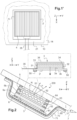
- FIG 1 is a front view on the exterior side of a rear window 1000 with two OLED examples with collimated light redirected according to the invention, therefore in the direction of the exterior face F1 11 of the first sheet of glass, for example monolithic 1.
- the OLEDs are powered by a connector 35 protruding from the edge of the glass and optionally the latter is masked from the outside by a peripheral masking layer, in particular black enamel (not shown) on face F2.
- a peripheral masking layer in particular black enamel (not shown) on face F2.
- the OLEDS as a variant can form a pictogram .
- FIG. 1a is a front detail view of the OLED 3 (one or more contiguous or separate OLEDs, for example each rectangular) provided on the exit surface 30' side with its collimating optics in a network of prisms extending along the horizontal H surmounted by that of redirection 5 in a network of asymmetrical prisms extending along the horizontal H.
- the OLED 3 one or more contiguous or separate OLEDs, for example each rectangular
- FIG. 1' a is an alternative front detail view of several OLEDs 3 placed side by side (for example each square or rectangular) provided with their collimation and redirection optics 5. Between the OLEDs the optics (non-functional parts 55') can be of reduced width or even zero or no texturing.
- One or more transparent and thin optical films for example of rectangular shape (constant or reduced width between the OLEDs as already stated), in particular a stack of two or three or more films, are also preferred for each lens.
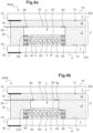
- FIG 1i is an overview of a collimating optic according to the invention.
- FIG 1X is a cross-sectional view of the collimation optics with pointed vertices S and the representative angles of the prisms (angle at the vertex, angle with plane of the prismatic optical film).
- the collimation optic 5a is here a prismatic optical film which will be for example fixed at the periphery by a double-sided adhesive or glue to the exit surface (generating an air gap at the entrance) of the OLED. It is for example a plastic film, for example, less than 0.3 mm thick and made of PET that is partially textured in thickness. It comprises on the front face a network of prisms 50 preferably contiguous and even symmetrical with vertices S and with a pitch T between vertices which is from 10 ⁇ m to 500 ⁇ m extending longitudinally along an axis forming an angle of at most 10° with the reference direction (here the horizontal for the bezel or alternatively a windshield) and even parallel.
- Each prism is defined by two longitudinal faces 41,42 each prism has an apex angle ranging from 60 to 110°, better still 90° and each longitudinal face forms with the plane of the optical film 4 an angle ranging from 30 to 55° better of 45°.
- the pitch is 160 ⁇ m and the height 80 ⁇ m and the remaining thickness is 175 ⁇ m with an angle at the top and on the valley side of 90° (+-20 arc).
- Air is between the output surface of the OLED and the input face of this single optical film 5a of the collimating optics.
- Air is between the prisms of the front face of the collimation optics, the tops of the patterns of each front face are in physical contact with the face F2.
- FIG. 1' is a front detail view on the outside of the OLED with the collimation and redirection optics 5 glued on the periphery, for example facing the technical edges (on the support 3') of the OLED 3.
- the longitudinal axis of the prisms is the horizontal between the sides of the telescope (or the windshield).
- the bonding can be framed and form a seal.
- FIG. 1Y is an overview of another collimating optic 4 according to the invention. This figure differs from the figure 1X in that the vertices are rounded and the side faces curved, the angles representative of the prisms are defined (angle at the vertex, angle with the plane of the film) from the two secant straight lines b1, b2 at A passing through the points of inflection I1 ,I2. The radius of curvature is also limited.
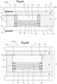
- FIG. 1j is an overview of a collimating optic according to the invention.
- This figure differs from 1i in that to form the collimating optics, a second identical prismatic film 5b is added and crossed at 90° and for example glued (welded, etc.) at the periphery to the first prismatic film 5a.
- collimating optics 4 (always a textured plastic film partially in thickness, for example in PET and less than 0.6 mm) bears two-dimensional patterns.
- Each two-dimensional pattern being defined by a side e in a plane P normal to the film 5a, the two-dimensional pattern has an apex angle ranging from 60 to 110°, each intersection of the side with the plane P forming with the plane of the film an angle ranging from 30 to 55°. Preferably one chooses angle at the top (in the plane P) of 90° and the 2 other angles of 45°.
- the two-dimensional patterns are here in relief, the tops of the patterns of each front face are free or in physical contact with a transparent element (face F2 of the exterior glazing for example), air is between the two-dimensional patterns.
- the two-dimensional patterns are hollow
- the network of two-dimensional patterns is a network of cavities
- the vertices S are oriented (towards the interior of the passenger compartment (towards the face F3 laminated glazing) and the upper surface of each cavity is free or in physical contact with a transparent element (second glazing, etc.), air is in the cavities.
- FIG 1Z is a front view of a redirection optic which will be on the front face of the collimation optic (fixed at the periphery, for example glued or welded or spaced apart by at most 1mm). It is an optical redirection film comprising an array of asymmetrical prisms with vertices and with a pitch T' between vertices which is from 10 ⁇ m to 500 ⁇ m, preferably with at least 4 or even 10 patterns facing the exit surface ( or emitting light),
- the redirection optics thus comprises a first optical film 5 which is asymmetric prismatic with, on a main face opposite the exit surface called the final front face, said network of asymmetric prisms extending longitudinally along a third axis forming an angle of at most 10°, at most 5° or at most 2° with said first axis and even parallel and/or with the reference direction of the glazing (the horizontal for the bezel) and even is parallel, in particular with a sub-millimeter thickness.
- Each asymmetrical prism is defined by first and second longitudinal faces, the prism preferably having a length L and a width W with L>2W and better still L>5W or L>10W.
- Each asymmetrical prism has an apex angle a'0 ranging from 50 to 60°, better 55° ⁇ 5°, 55° ⁇ 2° and the first longitudinal face 51 (known as the long side) forms a first angle with the plane of the film, ranging from 31 to 41° better than 35° ⁇ 5°, 35° ⁇ 2° (naturally the second longitudinal face (known as the short side) 52 forms a second angle with the plane of the film, ranging from 79 to 99° better than 85 at 90°, 88 to 90° preferably at most 90°
- the difference a4-a3 is greater than 40° and even 50°
- a set of two parallel optical films which are prismatic is even chosen asymmetrical.
- FIG 2 is a cross-sectional view of a monolithic rear window (bezel) with redirected collimated light OLED according to the invention according to one embodiment.
- This bezel 200 comprises a first transparent glazing 1 in mineral or organic glass, with main faces 11, 12 called faces F1 and F2, and an edge (0, and a so-called reference direction which is horizontal to the plane of the glazing ( domed or not).
- OLED 3 emits auto red towards face F2 and has an emitting surface with a length of at least 5cm and a width of at least 1cm, and is preferably of sub-millimeter thickness E0, with a half angle of emission at the top of 50° to 70° and a main emission direction normal to the plane of said OLED.
- this first film On the front face of this first film is fixed by peripheral gluing 62 a second optical film 5b with the second network of prisms extending longitudinally along a second axis forming an angle with said first axis of 90°, the first or the second axis forms a zero angle with the reference direction.
- a first optical redirection film 5 with an array of asymmetrical prisms with a long side 51 and a short side 52 extending longitudinally in the direction of reference
- the normal N to the large side directed towards the face F2 is oriented towards the top of the rear window or the windshield (for a redirection towards the ground).
- This redirection film is fixed by peripheral gluing 64 (glue, double face, etc.) to face F2 (or F4 if laminated) which is optional because here a rear protective film 7 (here two-layer 70, 71 covers and overflows the OLED and optical assembly 5a, 5b, 5 with glue 65. its main faces.
- the telescope is for example oriented between 12° and 80° from the ground and for example from 50 to 70°.
- the film bends the light at an angle of at least 15° towards the ground.
- the OLED 3 comprises a connector 35 protruding from the edge of the first glazing here fixed on the input surface side at the periphery
- the OLED 3 is rear-emitting comprising a support 3', which carries the side opposite the face F2 in this order, moving away from the support: a possible functional sub-layer 31, a transparent anode 32, an electroluminescent system organic material 33, a reflective cathode 34 and an encapsulation (resin) layer 36.
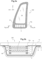
- FIG. 3a is a front view of a monolithic deflector 300 (side fixed window) with redirected collimated light OLED according to the invention.
- FIG. 3b is a cross-sectional view of the deflector (fixed side window) with redirected collimated light OLED according to the invention.
- This deflector comprises a first transparent glazing 1 in mineral or organic glass, with main faces 11, 12 called faces F1 and F2, and an edge 10, and a so-called reference direction which is normal to the horizontal plane of the glazing. (bulging or not). It is for example in the shape of a quadrilateral with an upper edge of reduced width. It comprises a masking layer 15 (black enamel, etc.) for example on face F2 and provided with a spare 15a.
- the OLED 3 is opposite the savings 15a and on the inside and emits auto yellow towards the face F2 and has an emitting surface with a length of at least 5cm and a width of at least 1cm, and is preferably d submillimeter thickness E0, with a half emission angle at the top of 50° to 70° and a main emission direction normal to the plane of said OLED.
- it is a rectangular light strip (or any other shape) at the bottom border.
- this first film On the front face of this first film is fixed by peripheral gluing 61 a second optical film 5b with the second array of prisms extending longitudinally along a second axis forming an angle with said first axis of 90°, the first or the second axis forms a zero angle with the reference direction.
- a first optical redirection film 5 with an array of asymmetrical prisms with a long side 51 and a short side 52 extending longitudinally in the reference direction.
- the normal N to the large side directed towards the face F2 is oriented towards the front of the deflector (for a rearward redirection.
- This redirection film is fixed by peripheral bonding 64 to face F2, which is optional because here a protective rear film 7 (here two-layer 70,71 covers and overflows the OLED and optical assembly 5a, 5b, 5 film with glue 65.
- a protective rear film 7 here two-layer 70,71 covers and overflows the OLED and optical assembly 5a, 5b, 5 film with glue 65.
- it is tinted or carries an electrically conductive functional layer 71 (solar control, etc.)
- the telescope is for example oriented between 12° and 80° from the ground and for example from 50 to 70°.
- the film bends the light at an angle of at least 15° towards the ground.
- the OLED 3 comprises a connector 35 protruding from the edge of the first glazing here fixed on the input surface side at the periphery.
- the enamel can be in front F2 and in F3 or F4 (each with a reserve).
- FIG. 3c is a front detail view of the OLED 3 provided with its collimation optics in an array of prisms extending along the horizontal H and that of redirection 5 in an array of asymmetrical prisms extending along the vertical on the surface side exit 30'.
- FIG. 3b is an alternative front detail view of several OLEDs 3 joined together provided with their collimation and redirection optics 5 between the oleds the optics (non-functional) can be of reduced width or even equal to zero or without texturing.
- FIG. 4a is a sectional view of a glazing 400a (bezel or deflector or windshield) with collimated and redirected light according to the invention.
- an electroluminescent element which is an OLED 3, (or OLED or a TFEL) and capable of emitting auto red light to form a brake light or other light (or auto yellow for turn signal repeater) or serves for external signage (pictogram, etc.) towards face F2 12, OLED having an output surface 30 towards face F2 and an opposite input surface 30 in the bottom of opening 2a.
- the OLED comprises a connector 35 protruding from the edge of the first glazing here fixed on the input surface side at the periphery.
- the OLED is rear-emitting, for example.
- a holographic redirection optic having a rear face on the output surface side and a front face opposite the rear face.
- the emerging opening 2a surrounds the OLED 4, the optics 4.5 and even in contact with its edge or, as a variant, spaced apart by at most 0.5 mm and even by at most 0.1 mm from the edge.
- a first sheet 21 is chosen, made of PVB, with a through opening (or blind as a variant) and a second rear sheet of PVB 22 on the rear face side 30.
- the two sheets are joined with or without a discernible interface (here in dotted lines).
- the OLED 3 is prefixed to the rear sheet 22 by gluing 60 or by placing in point adhesive contact by point heating (and pressure).
- the two sheets 21, 22 can be placed in point adhesive contact outside the zone of the OLED 3 before or after the installation between the two panes 1, 1'.
- the collimating optics 4 is here a prismatic optical film or preferably with two-dimensional patterns (especially if single) fixed at the periphery by a double-sided adhesive or a glue 60 to the exit surface (generating an air gap at the entrance ). It is for example a partially textured plastic film with a thickness of less than 0.3 mm for example and made of PET. For example the pitch is 160 ⁇ m and the height 80 ⁇ m and the remaining thickness is 175 ⁇ m with angle at the top and valley side of 90° (+-20 arc). Air is between the exit surface and the entry face of this first single optical film of the collimating optics. Air is between the patterns (prisms etc) of the front face of the collimating optics 4, the tops of the patterns are in physical contact with the redirection optics 5.
- the redirection optic 5 is here an asymmetrical prismatic optical film against or preferably as here fixed at the periphery by a double-sided adhesive or glue 60 to the front face of the optic 4 (generating an air gap at the inlet of the redirection optics 5) and preferably against or as here fixed at the periphery by a double-sided adhesive or a glue 60 to the face F2 (generating an air gap at the outlet). Air is between the prisms of the front face of the redirection optics, the tops of the patterns are possibly in physical contact with the face F2 12.
- the stack of the two films 4, 5 can be very thin.
- FIG. 4b is a sectional view of a glazing 400b (bezel or deflector or windshield) with collimated and redirected light according to the invention.
- This figure differs from the figure 4a in that the collimation optics 4 and that of redirection 5 are wider than the OLED 3 and than the emerging opening (than the through opening of the second sheet 21) and is here fixed (or against) on the face PVB 21 by gluing 62 or before lamination by bringing adhesive into point contact by point heating (and pressure).
- the redirection optic 5 is here an asymmetric prismatic optical film against or preferably as here fixed at the periphery by a double-sided adhesive or glue 60 to the front face of the optic 4 (generating an air gap at the inlet ) and preferably against or as here fixed at the periphery by a double-sided adhesive or a glue 60 to the face F2 12. Air is between the prisms of the front face of the redirection optics, the tops of the patterns are possibly in physical contact with face F2.
- FIG. 4c is a sectional view of a glazing 400c (bezel or deflector or windshield) with collimated and redirected light according to the invention.
- This figure differs from the previous one in that the collimation optics 4 and the redirection optics 5, still in the emerging opening, are wider than the OLED 3 and the collimation optics 4 are glued together 61 to PVB 22 (front face of rear PVB sheet 22) with or without spacer aid.
- the redirection optic 5, is against or as here fixed at the periphery by a double-sided adhesive or a glue 60 to the face F2 12.
- FIG. 400d is a sectional view of a glazing 400d (bezel or deflector or windshield) with collimated and redirected light according to the invention.
- This figure differs from the figure 4a in that the opening in the PVB is internal.
- a front PVB sheet 23 was placed on sheet 21 with opening (became central sheet).
- This film 7 can be a colored filter (white OLED and red or yellow filter etc).
- the redirection optic 5, here is an asymmetric prismatic optical film against or as here fixed at the periphery by a double-sided adhesive or glue 60 to the plastic protective film 7.
- FIG. 4e is a sectional view of a glazing 400e (bezel or deflector or windshield) with collimated and redirected light according to the invention.
- the plastic protective film 7 is a film covering, for example, less than 0.3 mm and made of PET which is glued to the periphery of the front face of the prismatic optical film 5 for redirection and/or simply covers (closes) the through-hole. It is in adhesive contact with the front PVB 23, for example preassembled with (functional PET/front PVB together before lamination) and with the PVB 21 (outside the opening area).
- This film 7.71 can be tinted and/or have an electrically conductive functional coating 72 on the face side F2 or F3: solar control, low E, etc.
- the redirection optic 5, here is an asymmetric prismatic optical film against or as here fixed at the periphery by a double-sided adhesive or glue 60 to the plastic protective film 7.
- FIG. 5 is a cross-sectional view of a glazing 500 (bezel or deflector or windshield) with redirected collimated light OLED according to the invention.
- This figure differs from the 4d figure in that a second identical prismatic film 4' is added crossed at 90° and glued (welded, etc.) at the periphery 61 to the first prismatic film and to the redirection film 5.
- the redirection optic 5, here is an asymmetric prismatic optical film against or as here fixed at the periphery by a double-sided adhesive or glue 60 to the plastic protective film 7.
- FIG. 6a is a cross-sectional view of a glazing 600a (bezel or deflector or windshield) with OLED with redirected collimated light according to the invention.
- This figure differs from the figure 4a in that the collimating optics 4 (always a textured plastic film, for example PET and less than 0.6 mm) carries two-dimensional patterns.
- the collimating optics 4 (always a textured plastic film, for example PET and less than 0.6 mm) carries two-dimensional patterns.
- Each two-dimensional pattern being defined by a side and, in a plane P normal to the film, the two-dimensional pattern has an apex angle ranging from 60 to 110°, each intersection of the side with the plane P forming with the plane of the film an angle ranging from 30 to 55°.
- the apex angle (in the plane P) of 90° and the other angles of 45° are chosen.
- the redirection optic 5 is here an asymmetrical prismatic optical film against or as here fixed at the periphery by a double-sided adhesive or glue 60 to the face F2.
- FIG. 6b is a sectional view of a glazing 600b with redirected collimated light OLED according to the invention.
- This figure differs from the figure 6a in that the collimating optics 4 is glued to a spacer frame 163a surrounding the OLED 3 for example against or glued to the rear PVB 22.
- FIG. 7a is a view showing an assembly step outside lamination of the OLED 3 with the collimation optics 4 and that of redirection 5 on a first interlayer PVB sheet of lamination 22 with the aim of producing the vehicle glazing according to the invention.
- the collimation optics (a prismatic film or two films crossed or with 2D patterns) is premounted on the OLED 3 by peripheral bonding as well as the redirection optics 5 on the collimation optics.
- a second sheet 21 is used with a through opening housing the assembly with the connector 35 protruding (on the input surface side of the OLED 3).
- the whole is placed on the back sheet 22 (face 22b) with possible local adhesive contact by heating and/or roller pressure) between PVB 21 and PVB 22 outside the OLED zone or between OLED and PVB 22 and/or between the connector and the PVBs 21, 22.
- the perforated sheet is first placed and it is lifted to place the OLED and optical assembly in the marked zone or zones.
- a third PVB sheet is added on the exit surface side (front PVB) it is necessary to use a local protective film or cover between the redirection optics and the rear face of this front PVB sheet.
- a transparent thin plastic film and even colored and white OLED
- a functional layer is added.
- FIG. 7b is a view showing an assembly step outside the lamination of the OLED with the collimation and redirection optics on a first interlayer PVB lamination sheet for the purpose of producing the glazing according to the invention.
- This figure differs from the previous one in that the rear surface of the OLED is fixed by gluing 60 to the rear sheet 22.
- a third PVB sheet is added on the output surface side (front PVB) it is necessary to use a local or covering protective film between the redirection optics 5 and the rear face of this front PVB sheet. For example, a transparent thin plastic film and even a functional layer is added.
- FIG. 7c is a view showing an assembly step outside the lamination of the OLED with the collimation and redirection optics on a first interlayer PVB lamination sheet for the purpose of producing the glazing according to the invention.
- An aid to the positioning of the OLED is provided by a film 90 with a mark 91 either non-stick against the face 22a or opposite the transparent table (glass) for laminating.
- a third PVB sheet is added on the output surface side (front PVB) it is necessary to use a local or covering protective film between the redirection optics 5 and the rear face of this front PVB sheet.
- a local or covering protective film between the redirection optics 5 and the rear face of this front PVB sheet.
- it is a transparent thin plastic film and even functional layer.
- FIG. 7d is a view showing an assembly step outside the lamination of the OLED with the collimation and redirection optics on a first interlayer PVB lamination sheet for the purpose of producing the glazing according to the invention.
- This figure differs from the figure 7a in that the collimating optic 4 and that of redirection 5 are wider than the through hole 25 of the PVB 21 and the collimating optic 4 is fixed against the front face of the perforated PVB sheet 21 by gluing or, as a variant, by placing in adhesive contact (heating and/or pressure). Optics 4 closes the hole and is spaced from OLED 3.
- a third PVB sheet is added on the exit surface side (front PVB) it is necessary to use a local protective film or cover between the redirection optics and the rear face of this front PVB sheet.
- a local protective film or cover between the redirection optics and the rear face of this front PVB sheet.
- it is a transparent thin plastic film and even functional layer.
- FIG. 7e is a view showing an assembly step outside the lamination of the OLED with the collimation and redirection optics on a first interlayer PVB lamination sheet for the purpose of producing the glazing according to the invention.
- This figure differs from the figure 7c in that the collimating optic 4 wider than the OLED is fixed against the front face of the rear sheet 22 by gluing 52 with or without a spacer.
- a third PVB sheet is added on the exit surface side (front PVB) it is necessary to use a local or covering protective film between the redirection optics 5 and the face back of this front PVB slip.
- a local or covering protective film between the redirection optics 5 and the face back of this front PVB slip.
- it is a transparent thin plastic film and even functional layer.
- FIG. 7f is a view showing an assembly step outside the lamination of the OLED with the collimation and redirection optics on a first interlayer PVB lamination sheet for the purpose of producing the glazing according to the invention.
- This figure differs from the figure 7b in that the second PVB sheet 23 comprises a blind opening 25, the redirection optic 5 is protected from the bottom by a local protective plastic film in the opening.
- FIG. 7g is a view showing an assembly step outside the lamination of the OLED with the collimation and redirection optics on a first interlayer PVB lamination sheet for the purpose of producing the glazing according to the invention.
- This figure differs from the figure 7f in that the protective film is glued to the bottom by gluing or bringing into local adhesive contact (heating and/or pressure).
Landscapes
- Physics & Mathematics (AREA)
- Engineering & Computer Science (AREA)
- Optics & Photonics (AREA)
- General Physics & Mathematics (AREA)
- Microelectronics & Electronic Packaging (AREA)
- Mechanical Engineering (AREA)
- Chemical & Material Sciences (AREA)
- General Engineering & Computer Science (AREA)
- Geochemistry & Mineralogy (AREA)
- Organic Chemistry (AREA)
- Materials Engineering (AREA)
- Life Sciences & Earth Sciences (AREA)
- General Chemical & Material Sciences (AREA)
- Chemical Kinetics & Catalysis (AREA)
- Electroluminescent Light Sources (AREA)
- Laminated Bodies (AREA)
- Joining Of Glass To Other Materials (AREA)
- Optical Elements Other Than Lenses (AREA)
- Vehicle Interior And Exterior Ornaments, Soundproofing, And Insulation (AREA)
- Lighting Device Outwards From Vehicle And Optical Signal (AREA)
Claims (27)
- Kraftfahrzeugverglasung mit Außenlichtsignalisierung, ausgewählt aus einer Seitenscheibe, einer Rückscheibe oder einer Windschutzscheibe, insbesondere eines Automobils (100), umfassend:- eine erste transparente Verglasung (1) aus Mineral- oder organischem Glas mit Hauptflächen (11, 12), die Fläche F1 und F2 genannt werden, und einer Kante (10) und einer Bezugsrichtung genannten Richtung- eine Lichtquelle (3) seitens der Fläche F2 und in der Lage, die Außenlichtsignalisierung zu emittieren, wobei die Lichtquelle eine Austrittsoberfläche zu der Fläche F2 Austrittsoberfläche aufweistdadurch gekennzeichnet, dass die Lichtquelle ein Elektrolumineszenzelement, das eine emittierende Oberfläche mit einer Länge von mindestens 5 cm und einer Breite von mindestens 1 cm aufweist und vorzugsweise von einer Dicke E0 im Submillimeterbereich ist, mit einem Emissionshalbwinkel an dem Scheitelpunkt von 50° bis 70° und einer Hauptemissionsrichtung senkrecht zu der Ebene des Elektrolumineszenzelements istdadurch, dass sie in einer Ausgestaltung gegenüber dem Elektrolumineszenzelement zwischen der Fläche F2 und dem Elektrolumineszenzelement eine Kollimationsoptik (5a, 5b) umfasst, die eine Rückfläche seitens der Austrittsoberfläche und eine der Rückfläche gegenüberliegende sogenannte Kollimationsvorderfläche aufweistwobei die Kollimationsoptik aus transparentem Material vorzugsweise von einer Dicke im Submillimeterbereich ist, einen optischen Film oder eine Anordnung optischer Filme vorweist, die jeweils auf einer Vorderfläche, die der Austrittsoberfläche gegenüberliegt, ein Netz von Motiven mit Scheitelpunkten und mit einem Abstand T zwischen Scheitelpunkten von 10 µm bis 500 µm vorweist, wobei die Kollimationsoptik vorweist:a) einen ersten optischen Film mit dem Netz von Motiven, die zweidimensional sind,b) oder eine Anordnung von mindestens zwei optischen Filmen, die prismatisch sind, vorzugsweise von höchstens zwei prismatischen optischen Filmen, vorweisend in dieser Reihenfolge von der Austrittsoberfläche ausgehend:- einen ersten optischen Film mit dem Netz von Motiven, bei denen es sich um Prismen handelt, die sich in Längsrichtung entlang einer ersten Achse erstrecken,- und gegenüber des ersten optischen Films einen zweiten optischen Film mit einem zweiten Netz von Motiven, bei denen es sich um Prismen handelt, die sich in Längsrichtung entlang einer zweiten Achse erstrecken, die mit der ersten Achse einen Winkel von 90±1 0° bildet, wobei die erste oder die zweite Achse mit der Bezugsrichtung einen Winkel von höchstens 10° bildet und sogar parallel istc) oder einen einzelnen ersten optischen Film mit dem Netz von Motiven, bei denen es sich um Prismen handelt, wobei das Netz sich in Längsrichtung entlang einer Achse erstreckt, die einen Winkel von höchstens 10° mit der Bezugsrichtung bildet und sogar parallel istdadurch, dass für a) jedes zweidimensionale Motiv durch eine Flanke definiert ist und das zweidimensionale Motiv in einer Ebene P senkrecht zu dem Film einen Scheitelwinkel von 60 bis 110° besitzt, wobei jeder Schnittpunkt der Flanke mit der Ebene P einen Winkel von 30 bis 55° mit der Ebene des optischen Films bildet,dadurch, dass für b) und c) jedes Prisma durch zwei Längsflächen definiert ist, wobei jedes Prisma einen Scheitelwinkel von 60 bis 110° besitzt und jede Längsfläche mit der Ebene des prismatischen optischen Films einen Winkel von 30 bis 55° bildetdadurch, dass sie gegenüber der Kollimationsoptik eine Umlenkoptik (5) zwischen der Kollimationsoptik und der Fläche F2 aus transparentem Material umfasst, einen optischen Umlenkfilm oder eine Anordnung von optischen Umlenkfilmen vorweist, die jeweils auf einer vorderen Hauptfläche gegenüberliegend der Austrittsoberfläche ein Netz asymmetrischer Prismen mit Scheitelpunkten und mit einem Abstand T' zwischen den Scheitelpunkten von 10 µm bis 500 µm vorweist, wobei die Umlenkoptik somit vorweist:i) einen asymmetrischen ersten optischen Film mit der Anordnung von asymmetrischen Prismen, die sich in Längsrichtung entlang einer dritten Achse erstrecken, die einen Winkel von höchstens 10° mit der Bezugsrichtung bildet und sogar parallel istj) oder eine Anordnung von zwei asymmetrischen optischen Filmen, die prismatisch sind, vorweisend in dieser Reihenfolge von der Austrittsoberfläche ausgehend:- einen ersten asymmetrischen optischen Film mit der Anordnung von asymmetrischen Prismen, die sich in Längsrichtung entlang einer dritten Achse erstrecken, die einen Winkel von höchstens 10° mit der Bezugsrichtung bildet- und gegenüber dem ersten asymmetrischen optischen Film einen zweiten asymmetrischen optischen Film mit einem zweiten Netz von prismatischen Motiven, wobei die Anordnung von Prismen des zweiten Netzes sich in Längsrichtung entlang einer vierten Achse erstreckt, die mit der dritten Achse einen Winkel von höchstens 10° bildet, und/oder die vierte Achse mit der Bezugsrichtung der Verglasung einen Winkel von höchstens 10° bildetdadurch, dass für i) oder j) jedes asymmetrische Prisma durch eine erste und eine zweite Längsfläche definiert ist, wobei jedes Prisma einen Scheitelwinkel von 50 bis 60° besitzt, und eine erste Längsfläche, die lange Seite genannt wird, mit der Ebene des asymmetrischen optischen Films einen Winkel im Bereich von 31° bis 41° bildetdadurch, dass:- die Bezugsrichtung für die Rückscheibe oder die Windschutzscheibe die Horizontale in der Ebene der Rückscheibe oder der Windschutzscheibe ist- und die Bezugsrichtung für die Seitenscheibe die Senkrechte zu der Horizontalen in der Ebene der Seitenscheibe ist- die Senkrechte zu der langen Seite, die zu der Fläche F2 gerichtet ist, zu der Oberseite der Rückscheibe oder der Windschutzscheibe oder zu der Vorderseite der Seitenscheibe ausgerichtet ist
und dadurch, dass- sich Luft zwischen der Austrittsoberfläche und der Eintrittsoberfläche des ersten optischen Films der Kollimationsoptik befindet,- sich für b) und c) Luft zwischen den Prismen der Vorderfläche der Kollimationsoptik befindet,- für a) die zweidimensionalen Motive vertieft sind, das Netz von zweidimensionalen Motiven ein Netz von Hohlräumen ist, die Scheitelpunkte S gegenüberliegend der Fläche F2 abgewandt ausgerichtet sind und die obere Oberfläche jedes Hohlraums von dem asymmetrischen prismatischen Film beabstandet oder in physischem Kontakt mit diesem ist, sich Luft in den Hohlräumen befindet oder die zweidimensionalen Motive reliefartig sind, die Scheitelpunkte der zweidimensionalen Motive jeder Vorderfläche beabstandet oder in physischem Kontakt mit dem asymmetrischen prismatischen Film sind, sich Luft zwischen den zweidimensionalen Motiven befindet- sich Luft zwischen den asymmetrischen Prismen befindet, die abschließende Vorderfläche des asymmetrischen prismatischen Films von einem transparenten Element beabstandet oder in physischem Kontakt mit diesem ist, das sich von der ersten Verglasung unterscheidet oder dieser entspricht
oder dadurch, dass in einer alternativen Ausgestaltung die Verglasung gegenüber der Austrittsoberfläche eine holografische Umlenkoptik vorweist, insbesondere aus transparentem Material, die holografische Umlenkoptik eine Vorderfläche zu der Fläche F2 und eine gegenüberliegende Rückfläche vorweist, die holografische Umlenkoptik einen Film mit einem Netz aus holografischen Motiven auf der Vorderfläche vorweist, und sich Luft zwischen der Austrittsoberfläche und der Eintrittsoberfläche der holographischen Umlenkoptik befindet und die Luft sich zwischen den reliefartigen holografischen Motiven der Vorderfläche der holografischen Umlenkoptik befindet oder die Luft sich in den vertieften holografischen Motiven der Vorderfläche der holografischen Umlenkoptik befindet, die Vorderfläche des holografischen Umlenkfilms von einem transparenten Element beabstandet oder in physischem Kontakt mit diesem ist, das sich von der ersten Verglasung unterscheidet oder dieser entspricht. - Fahrzeugverglasung mit Außenlichtsignalisierung nach dem vorstehenden Anspruch, dadurch gekennzeichnet, dass:- für die Rückscheibe die Lichtquelle vorzugsweise rot abstrahlt, wobei insbesondere die Anordnung von Lichtquelle und Kollimationsoptik und asymmetrischer Umlenkoptik ein (drittes) Bremslicht bildet oder die Anordnung von Lichtquelle und holographischer Umlenkoptik ein (drittes) Bremslicht bildet- oder für die Rückscheibe oder die Windschutzscheibe die Lichtquelle vorzugsweise gelb abstrahlt, insbesondere die Anordnung von Lichtquelle und Kollimationsoptik und asymmetrischer Umlenkoptik einen Blinker bildet, beispielsweise in Form eines Pfeils, oder die Anordnung von Lichtquelle und holografischer Umlenkoptik einen Blinker bildet, beispielsweise in Form eines Pfeils- und/oder für die Rückscheibe oder die Windschutzscheibe die Lichtquelle ein besonders aufmerksamkeitsstarkes Piktogramm wie ein Warndreieck oder eine Sicherheitsabstandsangabe ist.
- Fahrzeugverglasung mit Außenlichtsignalisierung nach einem der vorstehenden Ansprüche, dadurch gekennzeichnet, dass sie eine Vielzahl von Elektrolumineszenzelementen, insbesondere OLED oder TFEL oder QLED, jeweils mit der holografischen Umlenkoptik oder mit der Anordnung von Kollimationsoptik und asymmetrischer Umlenkoptik, insbesondere Lichtquellen in dem oberen Rand der Rückscheibe vorweist.
- Fahrzeugverglasung mit Außenlichtsignalisierung nach einem der Ansprüche 1 oder 3, dadurch gekennzeichnet, dass für die Seitenscheibe, insbesondere feststehend, als ein Deflektor, die Lichtquelle gelb abstrahlt, insbesondere die Anordnung von Lichtquelle und Kollimationsoptik und asymmetrischer Umlenkoptik einen Blink-Repeater bildet oder die Anordnung von Lichtquelle und holographischer Umlenkoptik einen Blink-Repeater bildet.
- Fahrzeugverglasung mit Außenlichtsignalisierung nach einem der vorstehenden Ansprüche, dadurch gekennzeichnet, dass die Prismen oder die zweidimensionalen Motive und vorzugsweise die asymmetrischen Prismen zusammenhängend oder im Wesentlichen zusammenhängend sind.
- Kraftfahrzeugverglasung mit Außenlichtsignalisierung nach einem der vorstehenden Ansprüche, dadurch gekennzeichnet, dass der oder jeder optische Film ein Kunststofffilm ist, der in seiner Dicke teilweise texturiert ist.
- Kraftfahrzeugverglasung mit Außenlichtsignalisierung nach einem der vorstehenden Ansprüche, dadurch gekennzeichnet, dass das Elektrolumineszenzelement eine OLED genannte organische Elektrolumineszenzdiode, insbesondere transparent (TOLED), oder eine QLED genannte Quantenpunkt-Elektrolumineszenzdiode ist.
- Kraftfahrzeugverglasung mit Außenlichtsignalisierung nach einem der vorstehenden Ansprüche, dadurch gekennzeichnet, dass sie, insbesondere für die OLED, einen Farbfilter umfasst, insbesondere einen Kunststofffilm mit Dicke im Submillimeterbereich, der ist:- zwischen der Austrittsoberfläche und der Rückfläche der Kollimationsoptik, insbesondere des ersten optischen Films
oder- zwischen der Austrittsoberfläche und der Eintrittsoberfläche der holografischen Umlenkoptik, insbesondere des optischen Films
oder- zwischen der Umlenkoptik und einer Verbundzwischenlage, wobei ein Filter dann einen Schutzfilm bildet. - Kraftfahrzeugverglasung mit Außenlichtsignalisierung nach einem der vorstehenden Ansprüche, dadurch gekennzeichnet, dass das Elektrolumineszenzelement eine rückseitig emittierende OLED ist, die einen Träger vorweist, der gegenüber der Fläche F2 in dieser Reihenfolge von dem Träger ausgehend trägt: eine eventuelle untere Funktionsschicht, eine transparente Anode, ein organisches Elektrolumineszenzsystem, eine reflektierende Kathode.
- Kraftfahrzeugverglasung mit Außenlichtsignalisierung nach einem der vorstehenden Ansprüche, dadurch gekennzeichnet, dass die erste Verglasung gekrümmt ist, das Elektrolumineszenzelement, insbesondere OLED oder QLED, flexibel ist.
- Kraftfahrzeugverglasung mit Außenlichtsignalisierung nach einem der vorstehenden Ansprüche, dadurch gekennzeichnet, dass sie ein elektrisches Anschlusselement für das Elektrolumineszenzelement vorweist, das mit dem Elektrolumineszenzelement verbunden ist und von der Kante der ersten Verglasung vorsteht.
- Kraftfahrzeugverglasung mit Außenlichtsignalisierung nach einem der vorstehenden Ansprüche, dadurch gekennzeichnet, dass die Kollimationsoptik an dem Elektrolumineszenzelement an einem Umfang der Austrittsoberfläche, vorzugsweise durch einen insbesondere transparenten Klebstoff, über ihre Rückfläche befestigt ist, und sogar von dem Umfang der emittierenden Fläche, befestigt ist, und dadurch, dass die asymmetrische Umlenkoptik an dem Umfang der endgültigen Vorderfläche an der Kollimationsoptik befestigt ist, insbesondere durch einen vorzugsweise transparenten Klebstoff, oder dadurch, dass die holografische Umlenkoptik an dem Elektrolumineszenzelement an dem Umfang der Austrittsoberfläche befestigt ist, über ihre Rückfläche, vorzugsweise durch einen insbesondere transparenten Klebstoff, und sogar der emittierenden Fläche befestigt ist.
- Kraftfahrzeugverglasung mit Außenlichtsignalisierung nach einem der vorstehenden Ansprüche, dadurch gekennzeichnet, dass sie eine Verbundverglasung vorweist, vorweisend:- die erste transparente Verglasung (1),- eine zweite transparente Verglasung (1') aus Mineral- oder organischem Glas, deren Hauptflächen (13, 14) Fläche F3 und F4 genannt werden,- zwischen den Flächen F2 und F3, die die Innenflächen der Verbundverglasung sind, eine transparente Verbundzwischenlage, gegebenenfalls getönt und/oder in ihrer Dicke zusammengesetzt, aus Polymermaterial (2, 20), einen Verbundzwischenlagenfilm, der eine Hauptfläche FA seitens der Fläche F3 und eine Hauptfläche FB seitens der Fläche F2 aufweist, Fläche FA, die in Klebekontakt mit Fläche F3 steht, und Fläche FB in Klebekontakt mit Fläche F2, wobei das Elektrolumineszenzelement sich zwischen den Flächen F2 oder F3 und vorzugsweise der Kollimationsoptik und der asymmetrischen Umlenkoptik zwischen den Flächen F2 oder F3 befindet oder die holografische asymmetrische Umlenkoptik sich zwischen den Flächen F2 oder F3 oder dem Elektrolumineszenzelement auf der Fläche F4 befindet und vorzugsweise die holografische asymmetrische Umlenkoptik sich seitens der Fläche F4 befindet, oder vorzugsweise sich die Kollimationsoptik und die asymmetrische Umlenkoptik seitens der Fläche F4 befinden.
- Kraftfahrzeugverglasung mit Außenlichtsignalisierung nach einem der vorstehenden Ansprüche, dadurch gekennzeichnet, dass die asymmetrische oder gegebenenfalls holografische Umlenkoptik an dem transparenten Element an dem Umfang der endgültigen Vorderfläche anliegt oder daran befestigt ist, beispielsweise an der Fläche F2 oder der Fläche F4 einer Verbundverglasung, die eine zweite transparente Verglasung (1') aus Mineral- oder organischem Glas vorweist, deren Hauptflächen (13, 14) Fläche F3 und F4 genannt werden, insbesondere durch einen vorzugsweise transparenten Klebstoff befestigt ist.
- Kraftfahrzeugverglasung mit Außenlichtsignalisierung nach einem der Ansprüche 1 bis 12, dadurch gekennzeichnet, dass sie eine Verbundverglasung vorweist, vorweisend:- die erste transparente Verglasung (1),- eine zweite transparente Verglasung (1') aus Mineral- oder organischem Glas, deren Hauptflächen (13, 14) Fläche F3 und F4 genannt werden,- zwischen den Flächen F2 und F3, bei denen es sich um die Innenseiten der Verbundverglasung handelt, eine transparente Verbundzwischenlage, vorzugsweise aus PVB, gegebenenfalls getönt und/oder gegebenenfalls in ihrer Dicke zusammengesetzt, aus polymerem Material (2), wobei der Verbundzwischenlagenfilm eine Hauptfläche FA seitens Fläche F3 und eine Hauptfläche FB seitens Fläche F2 aufweist, Fläche FA, die mit Fläche F3 in Klebekontakt steht, und Fläche FB, die mit Fläche F2 in Klebekontakt steht, wobei die Kollimationsoptik breiter als das Elektrolumineszenzelement ist und an dem Umfang befestigt, vorzugsweise durch einen insbesondere transparenten Klebstoff verklebt, oder an dem Umfang über ihre Rückfläche in Klebekontakt mit der Verbundzwischenlage steht, und gegebenenfalls die asymmetrische Umlenkoptik breiter als das Elektrolumineszenzelement ist und über ihre Rückfläche an der Kollimationsoptik an dem Umfang befestigt ist, vorzugsweise verklebt, insbesondere durch einen transparenten Klebstoff- oder die Kollimationsoptik an der Austrittsoberfläche an dem Umfang befestigt ist, vorzugsweise verklebt, insbesondere durch einen transparenten Klebstoff, und die asymmetrische Umlenkoptik breiter als das Elektrolumineszenzelement ist und an dem Umfang an der Verbundzwischenlage befestigt ist, vorzugsweise verklebt, insbesondere durch einen transparenten Klebstoff, oder über ihre Rückfläche an dem Umfang mit der Verbundzwischenlage in Klebekontakt steht
oder die holografische Umlenkoptik breiter als das Elektrolumineszenzelement ist und an der Verbundzwischenlage an dem Umfang befestigt ist, vorzugsweise verklebt, insbesondere durch einen transparenten Klebstoff, oder über ihre Rückfläche an dem Umfang mit der Verbundzwischenlage in Klebekontakt steht. - Kraftfahrzeugverglasung mit Außenlichtsignalisierung nach einem der Ansprüche 1 bis 15, dadurch gekennzeichnet, dass die Fläche F2 frei ist, die Verglasung monolithisch ist, sich die holografische oder asymmetrische Umlenkoptik auf der Fläche F2 befindet oder wenn die Verglasung ein Verbund ist und das Elektrolumineszenzelement sich seitens der freien Fläche F4 befindet:die gegebenenfalls holografische Umlenkoptik über ihre Rückfläche an dem Elektrolumineszenzelement an dem Umfang befestigt ist, vorzugsweise insbesondere durch einen vorzugsweise transparenten Klebstoff an dem Umfang der Austrittsoberfläche verklebtoder die Kollimationsoptik über ihre Rückfläche an dem Elektrolumineszenzelement an dem Umfang befestigt ist, vorzugsweise insbesondere durch einen vorzugsweise transparenten Klebstoff an dem Umfang der Austrittsoberfläche verklebtund/oder dadurch, dass die Anordnung von Elektrolumineszenzelement / Kollimationsoptik / asymmetrische Umlenkoptik oder die Anordnung von Elektrolumineszenzelement / holografischer Umlenkoptik an der freien Fläche F4 oder F2 befestigt ist, vorzugsweise über einen rückseitigen Schutzfilm, der sich auf der Eintrittsoberfläche des Elektrolumineszenzelement befindet, mit einem vorstehenden Befestigungsteil auf der freien Fläche F4 oder F2 verklebt.
- Kraftfahrzeugverglasung mit Außenlichtsignalisierung nach Anspruch 13, dadurch gekennzeichnet, dass sich die holographische Lenkoptik oder die Kollimationsoptik, vorzugsweise die Umlenkoptik, zwischen den Flächen F2 und F3 befindet, sich das Elektrolumineszenzelement zwischen den Flächen F2 und F3 und in der Zone mit dem Elektrolumineszenzelement die Fläche FA in Klebekontakt mit der Fläche F3 steht oder der Seite der Austrittsoberfläche, und die Fläche FB in Klebekontakt mit der Fläche F2 steht und das transparente Element ein Kunststoffschutzfilm ist, auf der endgültigen Vorderfläche, mit einer Fläche, die zu der Fläche F2 ausgerichtet ist und in Klebekontakt mit der Verbundzwischenlage steht, wobei der Kunststoffschutzfilm lokal ist, gegebenenfalls mit einer sogenannten Erweiterungszone, die von den Rändern der endgültigen Vorderfläche höchstens 10 cm vorsteht.
- Kraftfahrzeugverglasung mit Außenlichtsignalisierung nach einem der Ansprüche 14 bis 18, dadurch gekennzeichnet, dass die Verbundzwischenlage zusammengesetzt ist und außerhalb der Zone des Elektrolumineszenzelements folgenden Stapel vorweist: PVB/Funktionskunststofffilm gegebenenfalls mit elektrisch leitfähiger Funktionsbeschichtung seitens der Fläche F2 oder F3/PVB, wobei der Funktionskunststofffilm sich über die Fläche F2 erstreckt, und dadurch, dass das Elektrolumineszenzelement zwischen den Flächen F2 und F3 liegt, wobei zwischen der Vorderfläche und der Fläche F3 der Kunststofffilm/das PVB vorhanden ist, das transparente Element der Funktionskunststofffilm auf der Vorderfläche ist.
- Kraftfahrzeugverglasung mit Außenlichtsignalisierung nach einem der Ansprüche 12 bis 18, dadurch gekennzeichnet, dass die Verbundzwischenlage ein akustisches PVB vorweist und/oder getönt ist, wobei die Verbundzwischenlage insbesondere ein PVB ist, das mindestens teilweise in seiner Dicke getönt ist, wobei der getönte Teil mindestens zwischen dem Elektrolumineszenzelement und der Fläche F3 liegt.
- Kraftfahrzeugverglasung mit Außenlichtsignalisierung nach einem der Ansprüche 13 bis 19, dadurch gekennzeichnet, dass das Elektrolumineszenzelement in einer Öffnung der Verbundzwischenlage aufgenommen ist und vorzugsweise die Kollimationsoptik und die Umlenkoptik in der Öffnung aufgenommen sind, oder die holografische Lenkoptik in der Öffnung aufgenommen ist, die Öffnung eine Blindöffnung mit einem Boden in Richtung der Fläche F3 ist und in Fläche F2 mündet oder sich die sogenannte innere Öffnung in der Dicke der Verbundzwischenlage befindet und das transparente Element ein Schutzfilm ist, der in der inneren Öffnung aufgenommen ist oder der breiter als die innere Öffnung ist und die innere Öffnung bedeckt.
- Fahrzeug, das mindestens eine Lichtverglasung nach einem der vorstehenden Ansprüche vorweist.
- Verfahren zum Herstellen einer Kraftfahrzeugverglasung mit Außenlichtsignalisierung nach einem der vorstehenden Ansprüche, dadurch gekennzeichnet, dass es vor dem Platzieren auf die erste Verglasung ein Vormontieren auf das Elektrolumineszenzelement, insbesondere auf die Austrittsoberfläche, vorweist von:- der Kollimationsoptik als Film(e), insbesondere durch umlaufende Befestigung, sogar durch umlaufende Verklebung, die gegebenenfalls eine Dichtung bildet, und sogar der asymmetrischen Umlenkoptik als Film(e), insbesondere durch umlaufende Befestigung, sogar durch umlaufende Verklebung, die gegebenenfalls eine Dichtung bildet- oder der holografischen Umlenkoptik als Film, insbesondere durch umlaufende Befestigung, sogar durch umlaufende Verklebung, die gegebenenfalls eine Dichtung bildet- und sogar gegebenenfalls einem gegebenenfalls eingefärbten Schutzfilm auf dem letzten optischen Umlenkfilm, insbesondere durch umlaufende Befestigung, sogar durch umlaufende Verklebung, die gegebenenfalls eine Dichtung bildet.
- Verfahren zum Herstellen einer Kraftfahrzeugverbundverglasung mit Außenlichtsignalisierung nach einem der Ansprüche 13 bis 20,
dadurch gekennzeichnet, dass es die folgenden Schritte vorweist:- Positionieren des Elektrolumineszenzelements auf einer massiven Verbundzwischenlage oder in einer Blind- oder Durchgangsöffnung und gleichzeitiges oder getrenntes Positionieren der Kollimationsoptik und der asymmetrischen Umlenkoptik oder der holografischen Umlenkoptik gegenüber dem Elektrolum ineszenzelement
und nacheinander:- Platzieren der positionierten Anordnung zwischen der ersten und zweiten Verglasung- Zusammenlaminieren unter Vakuum und Erwärmung oder sogar Druckbeaufschlagung. - Verfahren zum Herstellen einer Kraftfahrzeugverbundverglasung mit Außenlichtsignalisierung nach dem vorstehenden Anspruch,
dadurch gekennzeichnet, dass das Positionieren des Elektrolumineszenzelements auf der Verbundzwischenlage in einer Blind- oder Durchgangsöffnung seitens der Eintrittsoberfläche erfolgt, mit der holografischen Umlenkoptik oder der Kollimationsoptik und sogar der asymmetrischen Umlenkoptik in der Öffnung aufgenommen und an dem Umfang der Austrittsoberfläche befestigt und vorzugsweise verklebt, oder mit der holografischen oder asymmetrischen Umlenkoptik, die die Öffnung abdeckt und auf der Verbundzwischenlage liegt. - Verfahren zum Herstellen einer Kraftfahrzeugverbundverglasung mit Außenlichtsignalisierung nach einem der vorstehenden Ansprüche,
dadurch gekennzeichnet, dass es vor dem Positionieren das Befestigen, insbesondere durch umlaufendes Verkleben eines gegebenenfalls eingefärbten lokalen Schutzfilms, auf der endgültigen Vorderfläche der asymmetrischen oder holografischen Umlenkoptik vorweist und während des Positionierens die Verbundzwischenlage ein Blindloch aufweist, das den lokalen Schutzfilm aufnimmt, oder die Verbundzwischenlage ein Durchgangsloch aufweist und eine weitere Verbundzwischenlage das Loch verschließt. - Verfahren zum Herstellen einer Kraftfahrzeugverbundverglasung mit Außenlichtsignalisierung nach einem der vorstehenden Ansprüche,
dadurch gekennzeichnet, dass die Verbundzwischenlage ein Durchgangsloch aufweist, welches das Elektrolumineszenzelement und die Kollimationsoptik und die asymmetrische Umlenkoptik oder das Elektrolumineszenzelement und die holografische Umlenkoptik aufnimmt, wobei das Verfahren das Platzieren eines gegebenenfalls eingefärbten Schutzfilms, der das Loch verschließt, und einer weiteren Zwischenlagenschicht, die den Schutzfilm bedeckt, wobei die weitere Zwischenlagenschicht gegebenenfalls bereits in Klebekontakt mit dem Schutzfilm steht, vorweist. - Verfahren zum Herstellen einer Kraftfahrzeugverbundverglasung mit Außenlichtsignalisierung nach einem der vorstehenden Ansprüche,
dadurch gekennzeichnet, dass es das punktuelle Bringen in Klebekontakt durch Erwärmen und Druck außerhalb der Elektrolumineszenzelementzone umfasst von- der Zwischenlagenschicht und einer weiteren Zwischenlagenschicht, die rückseitig genannt wird, seitens der Eintrittsoberfläche, und/oder der Zwischenlagenschicht und einer weiteren Zwischenlagenschicht, die vorderseitig genannt wird, auf der Vorderseite der Austrittsoberfläche,und/oder der Kollimationsoptik und der asymmetrischen Umlenkoptik oder der holografischen Umlenkoptik mit der Zwischenlagenschicht oder einer weiteren Zwischen lagensch ichtwobei sich das Elektrolumineszenzelement und sogar die Kollimationsoptik und die asymmetrische Umlenkoptik oder das Elektrolumineszenzelement und die holografische Umlenkoptik in einem Blindloch oder Durchgangsloch einer der Zwischenlagenschichten befinden und/oder das Elektrolumineszenzelement und sogar die Kollimationsoptik und die asymmetrische Umlenkoptik oder das Elektrolumineszenzelement und die holografische Umlenkoptik zwischen der Zwischenlagenschicht und der weiteren rückseitigen oder vorderseitigen Zwischenlagenschicht eingeschlossen sind.
Applications Claiming Priority (2)
| Application Number | Priority Date | Filing Date | Title |
|---|---|---|---|
| FR1761449A FR3074090B1 (fr) | 2017-11-30 | 2017-11-30 | Vitrage de vehicule a signalisation lumineuse externe, vehicule l'incorporant et fabrication. |
| PCT/FR2018/053022 WO2019106291A1 (fr) | 2017-11-30 | 2018-11-28 | Vitrage de vehicule a signalisation lumineuse externe, vehicule l'incorporant et fabrication |
Publications (2)
| Publication Number | Publication Date |
|---|---|
| EP3717432A1 EP3717432A1 (de) | 2020-10-07 |
| EP3717432B1 true EP3717432B1 (de) | 2023-08-02 |
Family
ID=61913266
Family Applications (1)
| Application Number | Title | Priority Date | Filing Date |
|---|---|---|---|
| EP18827194.4A Active EP3717432B1 (de) | 2017-11-30 | 2018-11-28 | Kraftfahrzeugverglasung für aussenlichtsignalisierung, fahrzeug damit und ihre herstellung |
Country Status (12)
| Country | Link |
|---|---|
| US (1) | US20200370727A1 (de) |
| EP (1) | EP3717432B1 (de) |
| JP (1) | JP7191956B2 (de) |
| KR (1) | KR102606457B1 (de) |
| CN (1) | CN110099875B (de) |
| BR (1) | BR112020008717A2 (de) |
| FR (1) | FR3074090B1 (de) |
| MA (1) | MA51214A (de) |
| MX (1) | MX2020005443A (de) |
| PE (1) | PE20201441A1 (de) |
| RU (1) | RU2020120327A (de) |
| WO (1) | WO2019106291A1 (de) |
Families Citing this family (11)
| Publication number | Priority date | Publication date | Assignee | Title |
|---|---|---|---|---|
| WO2020160492A1 (en) | 2019-02-01 | 2020-08-06 | Racing Optics, Inc. | Thermoform windshield stack with integrated formable mold |
| US11846788B2 (en) | 2019-02-01 | 2023-12-19 | Racing Optics, Inc. | Thermoform windshield stack with integrated formable mold |
| US12358265B2 (en) | 2019-08-30 | 2025-07-15 | Acr Ii Glass America Inc. | Laminated glazing having holographic film and method for producing a laminated glazing |
| KR102697670B1 (ko) * | 2019-11-28 | 2024-08-23 | 쌩-고벵 글래스 프랑스 | 중간층에 통합된 기능소자와 탈기구조를 갖는 복합 판유리 |
| CN111976430A (zh) * | 2020-08-24 | 2020-11-24 | 奇瑞汽车股份有限公司 | 汽车角窗玻璃总成及其汽车 |
| KR102608254B1 (ko) * | 2021-06-22 | 2023-12-01 | 현대모비스 주식회사 | 차량용 램프 및 그 램프를 포함하는 차량 |
| FR3124978B1 (fr) * | 2021-07-07 | 2023-11-24 | Saint Gobain | ÉLÉMENT vitrÉ pour la transmission de rayons lumineux infrarouges et procÉdÉ de fabrication de cet ÉlÉment vitrÉ |
| US12447895B2 (en) * | 2022-11-03 | 2025-10-21 | Pedestrian Safety Solutions, Llc | Visual front alert system |
| US12522132B2 (en) * | 2022-11-03 | 2026-01-13 | Pedestrian Safety Solutions, Llc | Visual front alert system |
| US12097800B2 (en) * | 2022-11-03 | 2024-09-24 | Pedestrian Safety Solutions, Llc | Visual front alert system |
| DE102024124503A1 (de) * | 2024-08-28 | 2026-03-05 | HELLA GmbH & Co. KGaA | Beleuchtungsvorrichtung für ein Kraftfahrzeug |
Family Cites Families (26)
| Publication number | Priority date | Publication date | Assignee | Title |
|---|---|---|---|---|
| DE69715567T3 (de) | 1996-11-26 | 2016-08-04 | Saint-Gobain Glass France S.A. | Verwendung einer Verbundglasscheibe zur Dämmung von durch Festkörper geleiteten Schwingungen in einem Fahrzeug |
| AU2002222923A1 (en) * | 2000-07-19 | 2002-01-30 | The Gates Corporation | Optical precipitation sensor |
| JP2003330111A (ja) * | 2002-05-10 | 2003-11-19 | Olympus Optical Co Ltd | 発光ユニット、照明装置、及び投影表示装置 |
| JP2005055481A (ja) * | 2003-06-09 | 2005-03-03 | Toyota Industries Corp | 光学素子、面状照明装置及び表示装置 |
| DE10336283A1 (de) * | 2003-08-08 | 2005-03-10 | Saint Gobain Sekurit D Gmbh | Flächenleuchtelement |
| FR2899954B1 (fr) * | 2006-04-13 | 2008-06-06 | Saint Gobain | Panneau lumineux |
| JP4910842B2 (ja) * | 2007-04-02 | 2012-04-04 | ソニー株式会社 | 光学シートおよび表示装置 |
| JP2009117195A (ja) * | 2007-11-07 | 2009-05-28 | Konica Minolta Holdings Inc | 面状光源及び指向性型照明装置、指向性可変型照明装置、擬似間接型照明装置 |
| JP2009146654A (ja) * | 2007-12-12 | 2009-07-02 | Nippon Zeon Co Ltd | 面光源装置及びその製造方法 |
| US20120026428A1 (en) * | 2009-03-30 | 2012-02-02 | Sumitomo Chemical Company, Limited | Liquid crystal display device |
| FR2964100B1 (fr) | 2010-08-24 | 2015-10-16 | Saint Gobain | Procede de selection d'un intercalaire pour un amortissement vibro-acoustique, intercalaire et vitrage comprenant un tel intercalaire |
| FR2966224B1 (fr) * | 2010-10-19 | 2012-12-14 | Valeo Vision | Dispositif d'eclairage ou de signalisation |
| JP2012142142A (ja) * | 2010-12-28 | 2012-07-26 | Nippon Zeon Co Ltd | 面光源装置 |
| US9541686B2 (en) | 2012-03-05 | 2017-01-10 | Saint-Gobain Glass France | Sheet with coating which reflects thermal radiation |
| FR2990948B1 (fr) | 2012-05-22 | 2019-08-30 | Saint-Gobain Glass France | Intercalaire plastique viscoelastique pour un amortissement vibro-acoustique et vitrage comprenant un tel intercalaire |
| US9696012B2 (en) * | 2012-10-04 | 2017-07-04 | Guardian Industries Corp. | Embedded LED assembly with optional beam steering optical element, and associated products, and/or methods |
| KR20160046889A (ko) | 2013-08-29 | 2016-04-29 | 코닝 인코포레이티드 | 얇은 유리 라미네이트 구조체 |
| CA2929112A1 (en) | 2013-10-29 | 2015-05-07 | Source 1 Environmental, Llc | Apparatus and method for repairing a pipe |
| ITTV20130190A1 (it) * | 2013-11-20 | 2015-05-21 | Automotive Lighting Italia Spa | Fanale automobilistico |
| FR3013631B1 (fr) | 2013-11-27 | 2017-04-28 | Saint Gobain | Intercalaire plastique viscoelastique pour un amortissement vibro-acoustique et vitrage comprenant un tel intercalaire |
| FR3017332B1 (fr) * | 2014-02-10 | 2016-02-19 | Saint Gobain | Vitrage lumineux avec isolateur optique. |
| CN105508958B (zh) * | 2014-10-13 | 2020-05-15 | 意大利汽车照明股份公司 | 汽车灯 |
| FR3034500A1 (fr) * | 2015-04-03 | 2016-10-07 | Saint Gobain | Vitrage lumineux de vehicule automobile et vehicule automobile avec un tel vitrage |
| DE102015106708B4 (de) * | 2015-04-30 | 2017-12-21 | Visteon Global Technologies, Inc. | Vorrichtung zur Emission von Licht, insbesondere zur Erzeugung eines Bildes |
| JP2017098104A (ja) * | 2015-11-25 | 2017-06-01 | 株式会社小糸製作所 | 発光装置 |
| FR3044971B1 (fr) * | 2015-12-14 | 2017-12-22 | Saint Gobain | Pare-brise feuillete de vehicule avec signaletique lumineuse interne. |
-
2017
- 2017-11-30 FR FR1761449A patent/FR3074090B1/fr active Active
-
2018
- 2018-11-28 EP EP18827194.4A patent/EP3717432B1/de active Active
- 2018-11-28 CN CN201880003748.3A patent/CN110099875B/zh active Active
- 2018-11-28 MX MX2020005443A patent/MX2020005443A/es unknown
- 2018-11-28 MA MA051214A patent/MA51214A/fr unknown
- 2018-11-28 WO PCT/FR2018/053022 patent/WO2019106291A1/fr not_active Ceased
- 2018-11-28 US US16/768,464 patent/US20200370727A1/en not_active Abandoned
- 2018-11-28 RU RU2020120327A patent/RU2020120327A/ru unknown
- 2018-11-28 JP JP2020529248A patent/JP7191956B2/ja active Active
- 2018-11-28 KR KR1020207017929A patent/KR102606457B1/ko active Active
- 2018-11-28 BR BR112020008717-3A patent/BR112020008717A2/pt not_active IP Right Cessation
- 2018-11-28 PE PE2020000831A patent/PE20201441A1/es unknown
Also Published As
| Publication number | Publication date |
|---|---|
| FR3074090A1 (fr) | 2019-05-31 |
| EP3717432A1 (de) | 2020-10-07 |
| JP2021504911A (ja) | 2021-02-15 |
| MX2020005443A (es) | 2020-08-27 |
| KR20200093586A (ko) | 2020-08-05 |
| FR3074090B1 (fr) | 2019-11-15 |
| MA51214A (fr) | 2020-10-07 |
| CN110099875A (zh) | 2019-08-06 |
| JP7191956B2 (ja) | 2022-12-19 |
| PE20201441A1 (es) | 2020-12-09 |
| KR102606457B1 (ko) | 2023-11-27 |
| US20200370727A1 (en) | 2020-11-26 |
| CN110099875B (zh) | 2022-07-01 |
| RU2020120327A3 (de) | 2021-12-30 |
| BR112020008717A2 (pt) | 2020-11-03 |
| RU2020120327A (ru) | 2021-12-30 |
| WO2019106291A1 (fr) | 2019-06-06 |
Similar Documents
| Publication | Publication Date | Title |
|---|---|---|
| EP3717432B1 (de) | Kraftfahrzeugverglasung für aussenlichtsignalisierung, fahrzeug damit und ihre herstellung | |
| EP3717239B1 (de) | Fahrzeugsonnendach, fahrzeug damit und dessen herstellung | |
| EP3463981B1 (de) | Verbundglasschiebedach eines fahrzeugs, fahrzeug damit und herstellung davon | |
| FR3051726B1 (fr) | Toit vitre feuillete lumineux de vehicule, vehicule l'incorporant et fabrication | |
| EP2861422B1 (de) | Glasdach mit leuchtmitteln und solchen zur kontrolle der lichttransmission | |
| WO2019106290A1 (fr) | Vitrage de vehicule a signalisation lumineuse externe, vehicule l'incorporant et fabrication | |
| BE1020715A3 (fr) | Toit vitre comportant des moyens d'eclairage. | |
| EP3463948B1 (de) | Fahrzeugscheibe für head-up-anzeige, fahrzeug damit und herstellung davon | |
| FR3051715A1 (fr) | Toit vitre feuillete lumineux de vehicule, vehicule l'incorporant et fabrication | |
| CA2966806A1 (fr) | Vitrage de signalisation lumineuse, vehicule l'incorporant et fabrication | |
| CA3060075A1 (fr) | Vitrage feuillete lumineux de vehicule a diodes electroluminescentes inorganiques et sa fabrication | |
| FR3165575A1 (fr) | Element vitre feuillete illuminable de vehicule, vehicule avec un tel element vitre feuillete illuminable | |
| FR3154940A1 (fr) | Vitrage feuilleté illuminable de véhicule | |
| FR3165574A1 (fr) | Element vitre feuillete illuminable de vehicule, vehicule avec une tel element vitre feuillete illuminable | |
| FR3154942A1 (fr) | Vitrage feuilleté illuminable de véhicule | |
| WO2025262279A1 (fr) | Vitrage feuillete illuminable de vehicule, vehicule avec un tel vitrage feuillete illuminable |
Legal Events
| Date | Code | Title | Description |
|---|---|---|---|
| STAA | Information on the status of an ep patent application or granted ep patent |
Free format text: STATUS: UNKNOWN |
|
| STAA | Information on the status of an ep patent application or granted ep patent |
Free format text: STATUS: THE INTERNATIONAL PUBLICATION HAS BEEN MADE |
|
| PUAI | Public reference made under article 153(3) epc to a published international application that has entered the european phase |
Free format text: ORIGINAL CODE: 0009012 |
|
| STAA | Information on the status of an ep patent application or granted ep patent |
Free format text: STATUS: REQUEST FOR EXAMINATION WAS MADE |
|
| 17P | Request for examination filed |
Effective date: 20200630 |
|
| AK | Designated contracting states |
Kind code of ref document: A1 Designated state(s): AL AT BE BG CH CY CZ DE DK EE ES FI FR GB GR HR HU IE IS IT LI LT LU LV MC MK MT NL NO PL PT RO RS SE SI SK SM TR |
|
| AX | Request for extension of the european patent |
Extension state: BA ME |
|
| DAX | Request for extension of the european patent (deleted) | ||
| RAV | Requested validation state of the european patent: fee paid |
Extension state: MA Effective date: 20200630 |
|
| GRAP | Despatch of communication of intention to grant a patent |
Free format text: ORIGINAL CODE: EPIDOSNIGR1 |
|
| STAA | Information on the status of an ep patent application or granted ep patent |
Free format text: STATUS: GRANT OF PATENT IS INTENDED |
|
| INTG | Intention to grant announced |
Effective date: 20230228 |
|
| RIN1 | Information on inventor provided before grant (corrected) |
Inventor name: BAUERLE, PASCAL Inventor name: DELRIEU, OLIVIER Inventor name: BERARD, MATHIEU |
|
| GRAS | Grant fee paid |
Free format text: ORIGINAL CODE: EPIDOSNIGR3 |
|
| GRAA | (expected) grant |
Free format text: ORIGINAL CODE: 0009210 |
|
| STAA | Information on the status of an ep patent application or granted ep patent |
Free format text: STATUS: THE PATENT HAS BEEN GRANTED |
|
| AK | Designated contracting states |
Kind code of ref document: B1 Designated state(s): AL AT BE BG CH CY CZ DE DK EE ES FI FR GB GR HR HU IE IS IT LI LT LU LV MC MK MT NL NO PL PT RO RS SE SI SK SM TR |
|
| REG | Reference to a national code |
Ref country code: GB Ref legal event code: FG4D Free format text: NOT ENGLISH |
|
| REG | Reference to a national code |
Ref country code: CH Ref legal event code: EP |
|
| REG | Reference to a national code |
Ref country code: DE Ref legal event code: R096 Ref document number: 602018054700 Country of ref document: DE |
|
| REG | Reference to a national code |
Ref country code: IE Ref legal event code: FG4D Free format text: LANGUAGE OF EP DOCUMENT: FRENCH |
|
| REG | Reference to a national code |
Ref country code: LT Ref legal event code: MG9D |
|
| REG | Reference to a national code |
Ref country code: NL Ref legal event code: MP Effective date: 20230802 |
|
| REG | Reference to a national code |
Ref country code: AT Ref legal event code: MK05 Ref document number: 1594582 Country of ref document: AT Kind code of ref document: T Effective date: 20230802 |
|
| PG25 | Lapsed in a contracting state [announced via postgrant information from national office to epo] |
Ref country code: GR Free format text: LAPSE BECAUSE OF FAILURE TO SUBMIT A TRANSLATION OF THE DESCRIPTION OR TO PAY THE FEE WITHIN THE PRESCRIBED TIME-LIMIT Effective date: 20231103 |
|
| PG25 | Lapsed in a contracting state [announced via postgrant information from national office to epo] |
Ref country code: IS Free format text: LAPSE BECAUSE OF FAILURE TO SUBMIT A TRANSLATION OF THE DESCRIPTION OR TO PAY THE FEE WITHIN THE PRESCRIBED TIME-LIMIT Effective date: 20231202 |
|
| PG25 | Lapsed in a contracting state [announced via postgrant information from national office to epo] |
Ref country code: SE Free format text: LAPSE BECAUSE OF FAILURE TO SUBMIT A TRANSLATION OF THE DESCRIPTION OR TO PAY THE FEE WITHIN THE PRESCRIBED TIME-LIMIT Effective date: 20230802 Ref country code: RS Free format text: LAPSE BECAUSE OF FAILURE TO SUBMIT A TRANSLATION OF THE DESCRIPTION OR TO PAY THE FEE WITHIN THE PRESCRIBED TIME-LIMIT Effective date: 20230802 Ref country code: PT Free format text: LAPSE BECAUSE OF FAILURE TO SUBMIT A TRANSLATION OF THE DESCRIPTION OR TO PAY THE FEE WITHIN THE PRESCRIBED TIME-LIMIT Effective date: 20231204 Ref country code: NO Free format text: LAPSE BECAUSE OF FAILURE TO SUBMIT A TRANSLATION OF THE DESCRIPTION OR TO PAY THE FEE WITHIN THE PRESCRIBED TIME-LIMIT Effective date: 20231102 Ref country code: NL Free format text: LAPSE BECAUSE OF FAILURE TO SUBMIT A TRANSLATION OF THE DESCRIPTION OR TO PAY THE FEE WITHIN THE PRESCRIBED TIME-LIMIT Effective date: 20230802 Ref country code: LV Free format text: LAPSE BECAUSE OF FAILURE TO SUBMIT A TRANSLATION OF THE DESCRIPTION OR TO PAY THE FEE WITHIN THE PRESCRIBED TIME-LIMIT Effective date: 20230802 Ref country code: LT Free format text: LAPSE BECAUSE OF FAILURE TO SUBMIT A TRANSLATION OF THE DESCRIPTION OR TO PAY THE FEE WITHIN THE PRESCRIBED TIME-LIMIT Effective date: 20230802 Ref country code: IS Free format text: LAPSE BECAUSE OF FAILURE TO SUBMIT A TRANSLATION OF THE DESCRIPTION OR TO PAY THE FEE WITHIN THE PRESCRIBED TIME-LIMIT Effective date: 20231202 Ref country code: HR Free format text: LAPSE BECAUSE OF FAILURE TO SUBMIT A TRANSLATION OF THE DESCRIPTION OR TO PAY THE FEE WITHIN THE PRESCRIBED TIME-LIMIT Effective date: 20230802 Ref country code: GR Free format text: LAPSE BECAUSE OF FAILURE TO SUBMIT A TRANSLATION OF THE DESCRIPTION OR TO PAY THE FEE WITHIN THE PRESCRIBED TIME-LIMIT Effective date: 20231103 Ref country code: FI Free format text: LAPSE BECAUSE OF FAILURE TO SUBMIT A TRANSLATION OF THE DESCRIPTION OR TO PAY THE FEE WITHIN THE PRESCRIBED TIME-LIMIT Effective date: 20230802 Ref country code: AT Free format text: LAPSE BECAUSE OF FAILURE TO SUBMIT A TRANSLATION OF THE DESCRIPTION OR TO PAY THE FEE WITHIN THE PRESCRIBED TIME-LIMIT Effective date: 20230802 |
|
| PG25 | Lapsed in a contracting state [announced via postgrant information from national office to epo] |
Ref country code: PL Free format text: LAPSE BECAUSE OF FAILURE TO SUBMIT A TRANSLATION OF THE DESCRIPTION OR TO PAY THE FEE WITHIN THE PRESCRIBED TIME-LIMIT Effective date: 20230802 |
|
| PG25 | Lapsed in a contracting state [announced via postgrant information from national office to epo] |
Ref country code: ES Free format text: LAPSE BECAUSE OF FAILURE TO SUBMIT A TRANSLATION OF THE DESCRIPTION OR TO PAY THE FEE WITHIN THE PRESCRIBED TIME-LIMIT Effective date: 20230802 |
|
| PG25 | Lapsed in a contracting state [announced via postgrant information from national office to epo] |
Ref country code: SM Free format text: LAPSE BECAUSE OF FAILURE TO SUBMIT A TRANSLATION OF THE DESCRIPTION OR TO PAY THE FEE WITHIN THE PRESCRIBED TIME-LIMIT Effective date: 20230802 Ref country code: RO Free format text: LAPSE BECAUSE OF FAILURE TO SUBMIT A TRANSLATION OF THE DESCRIPTION OR TO PAY THE FEE WITHIN THE PRESCRIBED TIME-LIMIT Effective date: 20230802 Ref country code: ES Free format text: LAPSE BECAUSE OF FAILURE TO SUBMIT A TRANSLATION OF THE DESCRIPTION OR TO PAY THE FEE WITHIN THE PRESCRIBED TIME-LIMIT Effective date: 20230802 Ref country code: EE Free format text: LAPSE BECAUSE OF FAILURE TO SUBMIT A TRANSLATION OF THE DESCRIPTION OR TO PAY THE FEE WITHIN THE PRESCRIBED TIME-LIMIT Effective date: 20230802 Ref country code: DK Free format text: LAPSE BECAUSE OF FAILURE TO SUBMIT A TRANSLATION OF THE DESCRIPTION OR TO PAY THE FEE WITHIN THE PRESCRIBED TIME-LIMIT Effective date: 20230802 Ref country code: CZ Free format text: LAPSE BECAUSE OF FAILURE TO SUBMIT A TRANSLATION OF THE DESCRIPTION OR TO PAY THE FEE WITHIN THE PRESCRIBED TIME-LIMIT Effective date: 20230802 Ref country code: SK Free format text: LAPSE BECAUSE OF FAILURE TO SUBMIT A TRANSLATION OF THE DESCRIPTION OR TO PAY THE FEE WITHIN THE PRESCRIBED TIME-LIMIT Effective date: 20230802 |
|
| REG | Reference to a national code |
Ref country code: DE Ref legal event code: R097 Ref document number: 602018054700 Country of ref document: DE |
|
| PG25 | Lapsed in a contracting state [announced via postgrant information from national office to epo] |
Ref country code: IT Free format text: LAPSE BECAUSE OF FAILURE TO SUBMIT A TRANSLATION OF THE DESCRIPTION OR TO PAY THE FEE WITHIN THE PRESCRIBED TIME-LIMIT Effective date: 20230802 |
|
| PLBE | No opposition filed within time limit |
Free format text: ORIGINAL CODE: 0009261 |
|
| STAA | Information on the status of an ep patent application or granted ep patent |
Free format text: STATUS: NO OPPOSITION FILED WITHIN TIME LIMIT |
|
| REG | Reference to a national code |
Ref country code: CH Ref legal event code: PL |
|
| PG25 | Lapsed in a contracting state [announced via postgrant information from national office to epo] |
Ref country code: MC Free format text: LAPSE BECAUSE OF FAILURE TO SUBMIT A TRANSLATION OF THE DESCRIPTION OR TO PAY THE FEE WITHIN THE PRESCRIBED TIME-LIMIT Effective date: 20230802 |
|
| 26N | No opposition filed |
Effective date: 20240503 |
|
| PG25 | Lapsed in a contracting state [announced via postgrant information from national office to epo] |
Ref country code: LU Free format text: LAPSE BECAUSE OF NON-PAYMENT OF DUE FEES Effective date: 20231128 |
|
| PG25 | Lapsed in a contracting state [announced via postgrant information from national office to epo] |
Ref country code: CH Free format text: LAPSE BECAUSE OF NON-PAYMENT OF DUE FEES Effective date: 20231130 |
|
| PG25 | Lapsed in a contracting state [announced via postgrant information from national office to epo] |
Ref country code: MC Free format text: LAPSE BECAUSE OF FAILURE TO SUBMIT A TRANSLATION OF THE DESCRIPTION OR TO PAY THE FEE WITHIN THE PRESCRIBED TIME-LIMIT Effective date: 20230802 Ref country code: LU Free format text: LAPSE BECAUSE OF NON-PAYMENT OF DUE FEES Effective date: 20231128 Ref country code: CH Free format text: LAPSE BECAUSE OF NON-PAYMENT OF DUE FEES Effective date: 20231130 Ref country code: SI Free format text: LAPSE BECAUSE OF FAILURE TO SUBMIT A TRANSLATION OF THE DESCRIPTION OR TO PAY THE FEE WITHIN THE PRESCRIBED TIME-LIMIT Effective date: 20230802 |
|
| REG | Reference to a national code |
Ref country code: BE Ref legal event code: MM Effective date: 20231130 |
|
| REG | Reference to a national code |
Ref country code: IE Ref legal event code: MM4A |
|
| PG25 | Lapsed in a contracting state [announced via postgrant information from national office to epo] |
Ref country code: IE Free format text: LAPSE BECAUSE OF NON-PAYMENT OF DUE FEES Effective date: 20231128 |
|
| PG25 | Lapsed in a contracting state [announced via postgrant information from national office to epo] |
Ref country code: BE Free format text: LAPSE BECAUSE OF NON-PAYMENT OF DUE FEES Effective date: 20231130 |
|
| PG25 | Lapsed in a contracting state [announced via postgrant information from national office to epo] |
Ref country code: IE Free format text: LAPSE BECAUSE OF NON-PAYMENT OF DUE FEES Effective date: 20231128 Ref country code: BE Free format text: LAPSE BECAUSE OF NON-PAYMENT OF DUE FEES Effective date: 20231130 |
|
| PG25 | Lapsed in a contracting state [announced via postgrant information from national office to epo] |
Ref country code: BG Free format text: LAPSE BECAUSE OF FAILURE TO SUBMIT A TRANSLATION OF THE DESCRIPTION OR TO PAY THE FEE WITHIN THE PRESCRIBED TIME-LIMIT Effective date: 20230802 |
|
| PG25 | Lapsed in a contracting state [announced via postgrant information from national office to epo] |
Ref country code: BG Free format text: LAPSE BECAUSE OF FAILURE TO SUBMIT A TRANSLATION OF THE DESCRIPTION OR TO PAY THE FEE WITHIN THE PRESCRIBED TIME-LIMIT Effective date: 20230802 |
|
| REG | Reference to a national code |
Ref country code: DE Ref legal event code: R081 Ref document number: 602018054700 Country of ref document: DE Owner name: SAINT-GOBAIN SEKURIT FRANCE, FR Free format text: FORMER OWNER: SAINT-GOBAIN GLASS FRANCE, COURBEVOIE, FR |
|
| PG25 | Lapsed in a contracting state [announced via postgrant information from national office to epo] |
Ref country code: CY Free format text: LAPSE BECAUSE OF FAILURE TO SUBMIT A TRANSLATION OF THE DESCRIPTION OR TO PAY THE FEE WITHIN THE PRESCRIBED TIME-LIMIT; INVALID AB INITIO Effective date: 20181128 |
|
| REG | Reference to a national code |
Ref country code: GB Ref legal event code: 732E Free format text: REGISTERED BETWEEN 20250703 AND 20250709 |
|
| PG25 | Lapsed in a contracting state [announced via postgrant information from national office to epo] |
Ref country code: HU Free format text: LAPSE BECAUSE OF FAILURE TO SUBMIT A TRANSLATION OF THE DESCRIPTION OR TO PAY THE FEE WITHIN THE PRESCRIBED TIME-LIMIT; INVALID AB INITIO Effective date: 20181128 |
|
| PGFP | Annual fee paid to national office [announced via postgrant information from national office to epo] |
Ref country code: FR Payment date: 20250930 Year of fee payment: 8 |
|
| VS25 | Lapsed in a validation state [announced via postgrant information from nat. office to epo] |
Ref country code: MA Free format text: FAILURE TO ELECT DOMICILE IN THE NATIONAL COUNTRY Effective date: 20231103 |
|
| PG25 | Lapsed in a contracting state [announced via postgrant information from national office to epo] |
Ref country code: TR Free format text: LAPSE BECAUSE OF FAILURE TO SUBMIT A TRANSLATION OF THE DESCRIPTION OR TO PAY THE FEE WITHIN THE PRESCRIBED TIME-LIMIT Effective date: 20230802 |
|
| PGFP | Annual fee paid to national office [announced via postgrant information from national office to epo] |
Ref country code: DE Payment date: 20250930 Year of fee payment: 8 |
|
| PGFP | Annual fee paid to national office [announced via postgrant information from national office to epo] |
Ref country code: GB Payment date: 20251001 Year of fee payment: 8 |