EP3717704B2 - Utilisation d'un dispositif pour un transfert de sédiment dans des étendues d'eau - Google Patents
Utilisation d'un dispositif pour un transfert de sédiment dans des étendues d'eau Download PDFInfo
- Publication number
- EP3717704B2 EP3717704B2 EP19701055.6A EP19701055A EP3717704B2 EP 3717704 B2 EP3717704 B2 EP 3717704B2 EP 19701055 A EP19701055 A EP 19701055A EP 3717704 B2 EP3717704 B2 EP 3717704B2
- Authority
- EP
- European Patent Office
- Prior art keywords
- sediment
- water
- measuring device
- receiving means
- use according
- Prior art date
- Legal status (The legal status is an assumption and is not a legal conclusion. Google has not performed a legal analysis and makes no representation as to the accuracy of the status listed.)
- Active
Links
Images


Classifications
-
- E—FIXED CONSTRUCTIONS
- E02—HYDRAULIC ENGINEERING; FOUNDATIONS; SOIL SHIFTING
- E02B—HYDRAULIC ENGINEERING
- E02B3/00—Engineering works in connection with control or use of streams, rivers, coasts, or other marine sites; Sealings or joints for engineering works in general
- E02B3/02—Stream regulation, e.g. breaking up subaqueous rock, cleaning the beds of waterways, directing the water flow
- E02B3/023—Removing sediments
-
- E—FIXED CONSTRUCTIONS
- E02—HYDRAULIC ENGINEERING; FOUNDATIONS; SOIL SHIFTING
- E02F—DREDGING; SOIL-SHIFTING
- E02F3/00—Dredgers; Soil-shifting machines
- E02F3/04—Dredgers; Soil-shifting machines mechanically-driven
- E02F3/88—Dredgers; Soil-shifting machines mechanically-driven with arrangements acting by a sucking or forcing effect, e.g. suction dredgers
- E02F3/8833—Floating installations
-
- E—FIXED CONSTRUCTIONS
- E02—HYDRAULIC ENGINEERING; FOUNDATIONS; SOIL SHIFTING
- E02F—DREDGING; SOIL-SHIFTING
- E02F3/00—Dredgers; Soil-shifting machines
- E02F3/04—Dredgers; Soil-shifting machines mechanically-driven
- E02F3/88—Dredgers; Soil-shifting machines mechanically-driven with arrangements acting by a sucking or forcing effect, e.g. suction dredgers
- E02F3/90—Component parts, e.g. arrangement or adaptation of pumps
- E02F3/92—Digging elements, e.g. suction heads
- E02F3/9243—Passive suction heads with no mechanical cutting means
-
- E—FIXED CONSTRUCTIONS
- E02—HYDRAULIC ENGINEERING; FOUNDATIONS; SOIL SHIFTING
- E02F—DREDGING; SOIL-SHIFTING
- E02F5/00—Dredgers or soil-shifting machines for special purposes
- E02F5/28—Dredgers or soil-shifting machines for special purposes for cleaning watercourses or other ways
-
- Y—GENERAL TAGGING OF NEW TECHNOLOGICAL DEVELOPMENTS; GENERAL TAGGING OF CROSS-SECTIONAL TECHNOLOGIES SPANNING OVER SEVERAL SECTIONS OF THE IPC; TECHNICAL SUBJECTS COVERED BY FORMER USPC CROSS-REFERENCE ART COLLECTIONS [XRACs] AND DIGESTS
- Y02—TECHNOLOGIES OR APPLICATIONS FOR MITIGATION OR ADAPTATION AGAINST CLIMATE CHANGE
- Y02A—TECHNOLOGIES FOR ADAPTATION TO CLIMATE CHANGE
- Y02A10/00—TECHNOLOGIES FOR ADAPTATION TO CLIMATE CHANGE at coastal zones; at river basins
Definitions
- the present invention relates to the use of a device for sediment transfer in water.
- the morphology of flowing waters and backwaters is influenced by the water, but also by suspended matter and sediments. Suspended matter and sediments can be found in the water of virtually all rivers and stagnant bodies of water. In the middle reaches of undeveloped rivers, sedimentation and erosion processes are usually in balance. In this state, the water bed changes only slightly. However, if a body of water is dammed or expanded, e.g. B. through artificial port facilities or storage basins or reservoirs for drinking water production and / or energy generation, the flow cross section and the flow speed in particular of the water below such dammed waters, in the so-called underwater, changes locally. As a result, increased sediment settles on the bottom of the dammed body of water.
- Sediment includes settled suspended particles, sand, soil material, but also organic material from plants and finally pebbles, etc. Sedimentation is particularly noticeable in reservoirs of hydroelectric power plants, such as. B. pumped storage power plants, in which water remains in relative calm between the individual operating processes, namely pumping operation and turbine operation. In these cases, the sediment deposited in the reservoir is no longer eroded over a long period of time, unlike in natural flowing waters, but increases in quantity at the bottom of the water over time, thereby reducing the usable depth and ultimately the usable volume for generating or storing energy.
- hydroelectric power plants such as. B. pumped storage power plants
- the WO 2008/122377 A1 proposes a method for transporting sediment from impounded waters, which is energetically efficient and with which it is possible to achieve a close approximation to a natural, undammed water system, especially in a tailwater of the impounded water.
- sediment deposits are picked up in a sediment area of a reservoir and transported to an erosion area near one or more drainage organs of a reservoir, whereby the sediments are transported into flowing waters by the erosion processes of the outflowing water caused by the flow.
- US 3,565,491 discloses a stationary shipping system, in particular for sand from a ditch or barge on land, for example a beach, using high-pressure water to stir up sand, for example, and thus produce a water-sand mixture near the inlet of a submersible pump, in order to obtain a mixture of liquid and solid components suitable for pumping with the submersible pump.
- the object of the present invention is to provide a method for transferring sediment in water that is improved compared to the prior art and a device suitable for this purpose, which is suitable for being used for a variety of sediment transfers.
- the present invention relates to the use of a device for sediment transfer in water.
- the device for sediment transfer in waters comprises at least one suction line, at least one receiving means for receiving sediment and at least one pressure line for transferring the collected sediment.
- At least one pumping device and at least one measuring device for determining a sediment concentration of the recorded sediment are arranged on the at least one recording means, the device further comprising a control unit which comprises a first interface for feeding in setpoints and a second interface for the at least one measuring device and a sediment concentration in the at least one suction line and/or in the at least one pressure line and a performance of the pumping device can be adjusted depending on this sediment concentration
- the control unit comprising a positioning system with at least one positioning means, so that a local position can be made available to the recording means via an interface and the device is designed to be movable on a body of water via the positioning system, the transfer of the sediment into at least one outflow organ of a dammed body of water, in the vicinity of at least one outflow organ of a dammed body of water, over a barrier structure of a dammed body of water
- the performance of the recording means can also be adjusted, which results in a change in the speed and/or water pressure, for example.
- the at least one receiving means and the at least one pump device are arranged spatially separated from one another, in particular separated by the at least one suction line.
- the suction line is formed or arranged between the receiving means and the suction side of the pump device, and is preferably designed as a hose.
- the pressure line is arranged downstream of the pump device on a pressure side of the same.
- the pressure line is preferably at least partially designed as a hose for transferring the collected sediment, for example on land, onto a ship, a raft or over a dam into an underwater area.
- an arrangement with a combined means of receiving means and pump device is also possible. This can then be arranged at the bottom of a body of water from which sediment is to be removed and transferred.
- an arrangement of the at least one pump device at a distance from the receiving means is preferred, preferably on a buoyant device, in particular a pontoon or boat or floatable platform, which can more preferably serve as a central device.
- two or more pump devices are provided, they can be installed on a single buoyant device, but alternatively also be arranged on several devices, for example each individual pump device on exactly one buoyant device.
- the at least one receiving means is arranged on a bottom, engaging in a bottom and/or above a bottom of a body of water.
- the at least one receiving means is arranged at a short distance, for example at a distance in a range of approximately 1 cm to approximately 100 cm from the bottom of the body of water.
- the at least one receiving means is arranged on the ground, it is dragged over the ground, especially if it is designed as a flushing head or milling machine, the latter also in combination with one or more flushing nozzles or suction nozzles.
- the one receiving means is assigned to a pump device, but two or more receiving means can also be assigned to a pump device.
- the advantage of a spaced arrangement of the at least one pumping device and the at least one receiving means is that the at least one receiving means can be guided over the bottom of a body of water by means of the at least one suction line without further securing due to the lower weight than in an embodiment with a combined pumping device , without the need for a separate control.
- a movability of the buoyant device is sufficient to guide the at least one receiving means.
- the position of the at least one receiving means can be clearly determined over a known length of the at least one suction line.
- the at least one measuring device can also be arranged behind the at least one pump device, so that the measurement of the sediment concentration can be carried out with high accuracy.
- the at least one measuring device is preferably arranged on the buoyant device following the at least one pump device, and more preferably separated from it by at least one compensator, as explained further below.
- the at least one recording means serves in particular to absorb sediment. Due to the arrangement of the at least one pump device downstream of the at least one receiving means, preferably spaced as described above, it picks up sediment by generating a suction effect and transports it in the direction of the at least one pump device.
- the at least one recording means also has prefers the function of loosening sediment from the bottom of a body of water and/or loosening it. Such a solution and/or loosening of sediment from a body of water is preferably carried out by applying hydraulic or mechanical force.
- the receiving means is preferably designed as a milling machine, suction nozzle, rinsing nozzle and/or suction head.
- the cutter engages in the sediment and loosens or separates it from the bottom of the water, and in doing so lies primarily on the bottom of the water.
- the one or more flushing nozzles or suction nozzles are arranged on the milling machine, preferably at a distance from the bottom of the water, in particular at a distance of about 1 cm to about 100cm.
- the at least one recording means is preferably positioned on a body of water. It is preferably connected to the at least one pump device via at least one suction line.
- the receiving means further preferably has a loosening function for sediment on a water bottom. For this purpose, it is preferably designed as a milling machine with at least one suction nozzle and/or rinsing nozzle, which is connected to at least one pump device via at least one suction line.
- the at least one receiving means is further preferably arranged at a distance from the at least one pump device, in particular as described above and further above, since sediment loosening can impair the pump function.
- a combination of a recording device with a sediment loosening function and a pumping device would also be too heavy to be moved safely across a body of water without additional aids.
- the at least one receiving means is guided via at least one suction line, and only via at least one suction line, connected to a buoyant device on the bottom of the water. Additional control means etc. are then not necessary and can be omitted. Due to its weight, the at least one recording means follows the surface of the water bottom and can pick up sediment there. If necessary, ballast means can also be arranged on the at least one receiving means if its own weight is not sufficient for guidance on the surface of the body of water.
- the receiving means can also be used with aids, for example more than one rope, more than one chain or combinations from this, relative to the floating device or devices, are held in position under water, the length and position of the aids being variable.
- the device advantageously makes it possible to achieve a targeted transfer of sediment from one body of water to another body of water, for example an underwater or a flowing body of water, or to a storage location outside of a body of water on land for the processing of the transferred sediment by treatment plants.
- the device and the method that can be carried out with it can therefore be used or carried out very cost-effectively.
- the device works fully automatically, so that the method that can be carried out on it can be carried out cost-effectively due to remote maintenance and control. This enables significant cost savings, particularly by saving working hours.
- a transferable sediment concentration can be determined, for example in the tailwater of a dammed body of water or a river into which the sediment is transferred, and based on a setpoint determined thereby, which is in particular a limit value of the transferable amount of sediment, via a feed into the control unit Device and depending on the at least one measuring device, a power of the at least one pump device and / or the at least one recording means can be adjusted such that a natural sediment concentration for an underwater or flowing water can be set.
- the control unit comprises a positioning system with at least one positioning means, so that a local position is transmitted to the recording means via an interface is available.
- a positioning system with at least one positioning means, so that a local position is transmitted to the recording means via an interface is available.
- This makes it possible to achieve targeted guidance of the recording medium on the bottom of a body of water.
- Further specifications can also be taken into account here, for example the position of a central unit in the device, preferably in the form of a buoyant device, preferably with at least one pontoon, which contains the control unit, but possibly also the at least one pump device and/or the at least one measuring device, includes.
- a pool level for example of a reservoir, as well as the length of the at least one suction line and a direction of travel of the device can be taken into account in order to provide a local position to the recording means or to determine and display the position of the recording means.
- the device is designed to be movable on a body of water via the positioning system.
- the movement of the device is advantageously continuous.
- the process takes place with regard to the at least one recording means and the at least one central unit.
- the central unit with the at least one pontoon can have drive means such as motors or propellers, but is particularly preferably designed to be movable via a cable winch system.
- Via the connection through the at least one suction line to the at least one receiving means a precise local positioning of the receiving means in accordance with the determined values is then made possible by a movement of the central unit with the at least one pontoon.
- the at least one measuring device is arranged downstream of the at least one pump device in a conveying direction of the collected sediment.
- the agitation of the sediment-water mixture by the at least one pump device avoids settling problems or stratification of a water column, so that the measurement carried out by the at least one measuring device produces at most little error-prone values with regard to the values to be determined provides sediment concentration.
- the measurement accuracy of the at least one measuring device is significantly increased by such an arrangement.
- the at least one measuring device is arranged in a conveying direction of the picked up and conveyed sediment of approximately 0.1 m to approximately 10 m, preferably approximately 0.3 m to approximately 5 m, even more preferably 0.5 m up to about 2 m behind the at least one pump device. If the distance between the at least one pump device and the at least one measuring device is significantly larger than 10 m, for example 20 m, the accuracy of the measured values for the sediment concentration decreases due to the then decreasing agitation or turbulence with settlement phenomena or stratification of sediment in the suction line and / or Pressure line, preferably in the pressure line or at least downstream of the at least one pump device.
- the at least one measuring device is arranged immediately following a compensator, which is part of the pressure line, or immediately following the at least one pumping device.
- At least one compensator for vibration damping or vibration suppression is arranged between the at least one pump device and the at least one measuring device.
- vibrations are also understood to mean vibrations, etc., which arise in particular from the at least one pump device, but also from a cable winch drive or motors or propellers to achieve movability of the device.
- the compensator makes it possible to suppress or reduce these vibrations, which would falsify the measurement result, also by influencing turbulence of the sediments on the pressure side of the pump device in front of the at least one measuring device.
- the at least one measuring device downstream of the compensator there is on the one hand sufficient, but on the other hand not excessive, turbulence of the sediments, so that a measurement can be carried out sensibly. It must also be taken into account that deposits and layers in the compensator itself or in a hose connected to it in front of the measuring device must be avoided, as these would falsify the measurement result.
- the compensator can be arranged immediately following the pump device, but also at a distance from it.
- the at least one measuring device is arranged downstream of the compensator in the conveying direction of the collected sediment, preferably immediately following it.
- the compensator is part of the pressure line, so that it provides a pressure line section between the pump device and the measuring device.
- the further part of the at least one pressure line is then arranged in the measuring device in the conveying direction of the picked up and conveyed sediment, which leads to a release of sediment.
- the compensator preferably has a length in a range from about 0.1 m to about 10 m, preferably about 0.1 m to about 5 m, even more preferably 0.1 m to about 2 m, measured from the connection to the at least one pump device.
- the compensator can be designed, for example, as a hose, a piece of hose, a stuffing box and/or a corrugated pipe.
- the target values are selected from a group comprising a target clearing area of the sediment to be transferred, delivery times, depth information of the water and/or limit values of the sediment concentration to be transferred.
- the limit values of the sediment concentration to be transferred which depends on a sediment requirement, for example of an underwater or a river into which the sediments are transferred, are relevant with regard to the regulation and setting of a sediment concentration in the pressure line and/or delivery line in the device.
- the process can then also be carried out efficiently and with the aim of creating a near-natural state, for example in an underwater environment.
- a target clearing area of the sediment to be transferred is specified, for example, by a reservoir and its formation of the basin floor as well as those areas in such a reservoir in which sediment deposits are present.
- the device is preferably controlled bathymetrically, i.e. the at least one recording means is locally controlled based on a topographical shape of the relevant water bottom, with this information being specified as target values.
- At least one sampling point with at least one sampling tap is provided. This allows an examination of the water quality of the sediment being pumped and to be transferred to be determined.
- the sampling point can also be provided in a bypass line in order to ensure long-term operation of the device and at the same time to take a sample of the sediment-water mixture that has been picked up and conveyed.
- a sampling point is preferably arranged subsequently in the at least one measuring device in the conveying direction of the sediment picked up and to be transferred.
- a method for transferring sediment in bodies of water is proposed, wherein sediment is picked up from the body of water by means of a pump device via a device, in particular one as described above, with at least one suction line with at least one receiving means and to another location via at least one pressure line is transferred, wherein a sediment concentration of the collected sediment in the at least one suction line and / or in the at least one pressure line in a conveying direction after the receiving means is determined via at least one measuring device and compared with target values via a control unit and a performance depending on the values determined in this way the at least one pumping device and/or the at least one recording means is controlled, a geographical location of the device being recorded via a positioning means of the control unit and compared with the setpoint values and the device being moved on the body of water depending on the position values determined in this way.
- the sediment With the method, it is advantageously possible for the sediment to be transferred into at least one outflow organ of a dammed body of water, in the vicinity of a drain organ of a dammed body of water, over a barrier structure of a dammed body of water or around this into an underwater, into a watercourse and / or can be made on land for storage at a storage location.
- the process is therefore very adaptable to the hydromorphological, can be adapted to the structural, geographical and other conditions of the body of water in question.
- the sediment transfer is particularly preferably carried out automatically.
- the at least one recording means is controlled bathymetrically in the method, i.e.
- the at least one recording means is locally controlled based on a topographical shape of the relevant body of water, with this information being specified as target values.
- the method can be carried out particularly efficiently, and in particular a working area restriction can be easily implemented in a body of water.
- the invention is not limited to the combinations of features shown in the figures. Rather, the features disclosed in the description, including the description of the figures, can be combined with those features specified in the figures.
- the exemplary embodiments for the method are as in the Fig. 2 and 3 shown are just some of the ways in which the process can be implemented.
- a recording means 16 or a central unit 32 can be designed differently. In particular, only a measurement, regulation and control of the device or an implementation of the method can take place on the basis of the determination of the sediment concentration of the conveyed sediments.
- a positioning system 40 can, but does not have to be, provided.
- At least one measuring device 20 and/or at least one sampling point 50 can also be arranged in at least one suction line 12, i.e. in front of a pump device 18.
- the at least one suction line 12 can also be extremely short and can only consist of a flange or other fastening with at least one receiving means 16 if the pumping device is arranged directly after the receiving means 16.
- the at least one pump device 18 and the at least one receiving means 16 can also be designed as a component with the at least one suction line 12.
- a plurality of receiving means 16 can also be arranged on a suction line 12.
- Several suction lines 12 and/or several pressure lines 14 can also be provided.
- Fig. 1 shows a schematic representation of the structure of the device 10 for a preferably automated sediment transfer in bodies of water 80.
- a body of water 80 which can be a dammed body of water such as a reservoir with a dam, but also a natural lake, a harbor basin or a river, these The list is not exhaustive, has a water bottom 82 and a water surface 84.
- a layer of sediment 70 has been deposited on the water bottom 82.
- the device 10 consists of a central unit 32 with a pontoon 34, which is designed to be movable. The movability is made possible via a positioning system 40 in conjunction with ropes 44.1 and 44.2 shown as examples, which are operated via corresponding winches 46.1 and 46.2.
- a motor for producing a process can also be provided on the pontoon 34, preferably in combination with at least one anchoring of the pontoon 34 in the body of water 80, or a propeller drive.
- a positioning means 42 which is connected to a control unit 22 via an interface 43 (see Fig. 4 ) is connected, whereby the positioning means can be designed, for example, as a GPS or other satellite receiver, the geographical location of the central unit 32 or the pontoon 34 are determined and transmitted to the control unit.
- the central unit 32 with the pontoon 34 is preferably moved continuously, in which case the receiving means 16 is then also moved and removes sediment 70 on the water bottom 82.
- a pump device 18 and, subsequently, a measuring device 20 are arranged on the pontoon 34 and thus the central unit 32, between which a compensator 19 is preferably provided in the example shown here.
- the compensator 19 can consist, for example, of a rubber hose, which preferably has a length of at least about 0.1 meter, preferably a length of up to about 10 meters.
- the length of the compensator is preferably between approximately 0.1 meters and 10 meters, more preferably between 0.3 meters and 5 meters, and even more preferably between 0.5 meters and 3 meters.
- the at least one measuring device 20 is preferably arranged after the at least one pump device 18 in the sense of the present invention. This avoids measurement errors that arise due to stratification in the conveyed sediment-water mixture or settling problems of the sediment 70.
- the at least one pump device 18 creates a stirring of the sediment-water mixture, which promotes measurement.
- the at least one measuring device 20 is therefore preferably arranged approximately 0.3 meters to approximately 5 meters behind the at least one pumping device.
- the at least one measuring device 20 can also be arranged under water.
- the at least one measuring device 20 can be designed, for example, as a Coriolis measuring device or density meter, as a radiometric measuring device or as a magnetic-inductive flow meter and carries out a mass flow measurement to determine a sediment concentration in the collected and conveyed sediment 70, preferred and as in Fig. 1 shown, in a pressure line 14 designed as a hose, which is designed to transfer the sediment 70.
- the at least one pressure line 14 is arranged on a pressure side of the at least one pump device 16 and represents a conveying means for the sediment 70.
- the pump device 18 is connected via a suction line 12, also designed as a hose, which is on a suction side of the pump device 18 is arranged, connected to a receiving means 16, which can be designed, for example, as a milling machine, suction nozzle, rinsing nozzle and / or suction head.
- a speed and/or a water pressure of the receiving means 16 can be adjusted.
- This setting can be set via the control unit 22, which is assigned to the central unit 32.
- the pump device 18 can be designed, for example, as a centrifugal pump, water jet pump, air lift device or rotary lobe pump. When using an air-lift device, compressed air is injected into the receiving means 16.
- the suction line 12 is the area between the receiving means 16 and the at least one injection point for the compressed air, which can also be located directly on the receiving means 16.
- Receiving means 16, suction line 12 and pump device 18 can be designed as one component in an air lift device.
- a sampling point 50 with a sampling tap 52 is arranged in the pressure line 14.
- a sample can be taken there, for example, to calibrate the device 10, but also to regularly check the mixture of sediment and water being conveyed.
- the pressure line 14 is, for example, held below the water surface 14 via a float 13.
- the central unit 32 with the pontoon 34 and the control unit 22 can be moved via the positioning system 40 in a direction of travel 36, shown by an arrow.
- the positioning system 40 can do more than just that Fig. 2 Include the rope winch system shown, but also, for example, propellers or other adjustment devices.
- Fig. 2 shows a dammed body of water 80 with an inflow 96 and a barrier structure 88 in the form of a dam with two drain elements 86.1 and 86.2, which correspond, for example, to a base drain of a dam.
- a central unit 32.1 in an embodiment of the method that is shown in Fig.
- a sediment delivery 60.1 in the vicinity of the drain element 86.1 sediment is conveyed and transferred, which then, as shown in the WO 2008/122377 A1 known, reaches an underwater 90 via the drain element.
- the drain element 86.1 is connected to a power plant unit 92, for example a turbine, via a tunnel 91, provided that the dammed water 80 also serves to generate energy.
- a second embodiment of the method according to Fig. 2 is conveyed and transferred via a central unit 32.2 and a pressure line 14.2 directly into a drain element 86.2, which in turn can be designed as a base drain, via a sediment delivery 60.2, so that it then reaches the underwater 90.
- Sediment picked up is conveyed via a central unit 32.3 and a pressure line 14.3 and transferred to a sediment delivery 60.3 directly into the underwater 90 around the barrier structure 88 or across it.
- Fig. 3 shows a further alternative embodiment of the method with a body of water 80 in the form of a harbor basin, which is connected to a watercourse 81.
- sediment is conveyed via a central unit 32.1 and a pressure line 14.1 and transferred to a storage location 94 for further processing of the sediment or its storage.
- Storage location 94 is on land.
- processing plants for the sediment 70 can be provided, for which it is important to be supplied with a predetermined amount of sediment 70.
- sediment is conveyed and transferred to a sediment delivery 60.1 via a central unit 32.2 and a pressure line 14.2 and delivered directly into the watercourse 81. The same happens, but from a different place within the harbor basin, in a third embodiment of the method via the central unit 32.3 and the pressure line 14.3 to release sediment 60.2 into the watercourse 81.
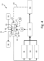
- Fig. 4 shows a schematic representation of the process for transferring sediment 70, preferably an automatic transfer, through which operating costs can be significantly reduced.
- the device 10 includes the central unit 32 with the pontoon 34. Shown schematically is the control unit 22, which processes data received or stored on the central unit 32 and uses this to regulate or control the recording means 16, the pumping device 18 and the positioning system 40.
- Setpoint values 24, which come from a source not specified here, are fed to a memory 26 via an interface 25.
- the target values are preferably selected from a group comprising a target clearing area of the sediment 70 to be transferred, delivery times, depth information of the body of water 80 and/or limit values of the transferable sediment concentration.
- the memory 26 does not have to be present; the setpoint values can also be transmitted online via remote data transmission, in particular continuously, or queried by the central unit 32, whereby temporary storage can be provided.
- 28 measured values, determined by the measuring device 20 are fed to the central unit 32 via an interface, as is also the case with regard to the positioning means 42 with the associated interface 43.
- Data obtained from the sediment output 60, such as turbidity values of an underwater, can also be transferred a feedback 62 and an interface 63 are recorded and taken into account.
- the determined values of the measuring device 20, the positioning means 42 and, if applicable, the values for the delivered sediment obtained via the feedback 62, which can be present, for example, in the form of turbidity measurements, are compared with the setpoint values 24 present in the storage unit 26 and from this instructions are given to the control unit 22 is provided, which performs a power of the pump device 18, but also possibly a speed or a water pressure of the receiving means 16 as well as a positioning of the device 10, in particular the pontoon 34 of the central unit 32, via the positioning system 40.
- the delivery takes place via the suction line 12 and the pressure line 14 for sediment delivery 60.
- the setpoint 24 for the limit value of the transferable Sediment concentration depends on the condition of the body of water into which the sediment 70 is transferred, for example a flowing water 81 or an underwater 90, or the storage location 94 with the processing plants for the sediment 70 located there.
- this setpoint 24 is relevant for the regulation the performance of the at least one pump device 18 and/or the at least one recording means 16 and/or the local position of the at least one recording means 16.
- the control unit 22 can send values via an interface 31 to at least one display means 30, which does not necessarily have to be present, pass on so that the corresponding values are made visible to an operator of the device 10.
- the corresponding values can also be logged and stored in the storage device 26. But other storage and display options are also conceivable.
- the method and the device 10 make it advantageously possible to carry out automated sediment transport in waters, in particular dammed waters, but also ports and other waters. What is essential here is the focus on a sediment concentration of the conveyed sediment, preferably on the pressure side of the at least one pump device in the at least one pressure line 14, so that an underwater or other body of water into which the sediment is transported or transferred is ecologically compatible and targeted can be supplied with the extracted and transferred sediment.
Landscapes
- Engineering & Computer Science (AREA)
- General Engineering & Computer Science (AREA)
- Mechanical Engineering (AREA)
- Civil Engineering (AREA)
- Structural Engineering (AREA)
- Mining & Mineral Resources (AREA)
- Environmental & Geological Engineering (AREA)
- Ocean & Marine Engineering (AREA)
- Treatment Of Sludge (AREA)
- Barrages (AREA)
- Sampling And Sample Adjustment (AREA)
Claims (7)
- Utilisation d'un dispositif (10) pour transférer des sédiments dans les corps d'eau (80, 81, 90)- doté d'au moins une conduite d'aspiration (12) avec au moins un moyen de collecte (16) pour collecter les sédiments (70) et- doté d'au moins une conduite de refoulement (14) transférer les sédiments collectés (70),- derrière l'au moins un moyen de réception (16) étant agencés au moins un dispositif de pompage (18) et au moins un dispositif de mesure (20) pour déterminer la concentration des sédiments collectés (70) et- le dispositif (10) comprenant en outre une unité de réglage (22) qui comprend une première interface (25) pour l'enregistrement des valeurs de consigne (24) et une deuxième interface (26) pour l'au moins un dispositif de mesure (20) et qui définit une concentration de sédiments dans l'au moins une conduite d'aspiration (12) et/ou dans l'au moins une conduite de refoulement (14) et régule une puissance du dispositif de pompage (18) en fonction de cette concentration de sédiments, l'unité de réglage (22) comprenant un système de positionnement (40) doté d'au moins un moyen de positionnement (42), de sorte qu'une position géographique peut être fournie au moyen de collecte (16) par une interface (43) et que le dispositif (10) peut être déplacé sur un corps d'eau (80) par le système de positionnement (40) et- dans laquelle le transfert des sédiments (70) a lieu dans au moins un organe d'évacuation (86.1, 86.2) d'un corps d'eau artificiel (80), à proximité d'au moins un organe d'évacuation (86.1, 86.2) d'un corps d'eau artificiel (80), au-dessus d'un ouvrage de retenue (88) d'un corps d'eau artificiel (80) ou autour de celui-ci dans un bief aval (90) et/ou dans un cours d'eau (81).
- Utilisation selon une ou plusieurs des revendications précédentes, caractérisé en ce que l'au moins un dispositif de mesure (20) est agencé en aval de l'au moins un dispositif de pompage (18) dans une direction de transport (15) des sédiments collectés (70).
- Utilisation selon une ou plusieurs des revendications précédentes, caractérisé en ce qu'entre l'au moins un dispositif de pompage (18) et l'au moins un dispositif de mesure (20) est agencé au moins un compensateur (19) pour supprimer ou amortir les vibrations.
- Utilisation selon une ou plusieurs des revendications précédentes, caractérisé en ce que les valeurs de consigne (24) sont sélectionnées parmi un groupe comprenant une zone spatiale de consigne des sédiments à transférer (70), des temps de transport, des indications de profondeur du corps d'eau (80) et/ou des valeurs limites de la concentration de sédiments à transférer.
- Utilisation selon une ou plusieurs des revendications précédentes, caractérisé en ce que celui-ci comprend au moins un point d'échantillonnage (50) avec au moins un robinet d'échantillonnage (52).
- Utilisation selon la revendication 5, caractérisé en ce que l'au moins un point d'échantillonnage (50) est agencé en aval de l'au moins un dispositif de mesure (20) dans la direction de transport (15) des sédiments collectés (70).
- Utilisation selon une ou plusieurs des revendications précédentes, caractérisé en ce que le transfert de sédiments est effectué automatiquement.
Applications Claiming Priority (2)
| Application Number | Priority Date | Filing Date | Title |
|---|---|---|---|
| DE102018104038 | 2018-02-22 | ||
| PCT/EP2019/050802 WO2019161996A1 (fr) | 2018-02-22 | 2019-01-14 | Dispositif pour un transfert de sédiment dans des étendues d'eau ainsi que procédé pour un transfert de sédiment dans des étendues d'eau |
Publications (3)
| Publication Number | Publication Date |
|---|---|
| EP3717704A1 EP3717704A1 (fr) | 2020-10-07 |
| EP3717704B1 EP3717704B1 (fr) | 2021-03-17 |
| EP3717704B2 true EP3717704B2 (fr) | 2024-01-24 |
Family
ID=65041733
Family Applications (1)
| Application Number | Title | Priority Date | Filing Date |
|---|---|---|---|
| EP19701055.6A Active EP3717704B2 (fr) | 2018-02-22 | 2019-01-14 | Utilisation d'un dispositif pour un transfert de sédiment dans des étendues d'eau |
Country Status (7)
| Country | Link |
|---|---|
| US (1) | US11041280B2 (fr) |
| EP (1) | EP3717704B2 (fr) |
| AU (1) | AU2019225774B2 (fr) |
| BR (1) | BR112020016733B1 (fr) |
| CA (1) | CA3090490C (fr) |
| ES (1) | ES2877328T5 (fr) |
| WO (1) | WO2019161996A1 (fr) |
Cited By (1)
| Publication number | Priority date | Publication date | Assignee | Title |
|---|---|---|---|---|
| DE102024103813A1 (de) | 2024-02-12 | 2025-03-27 | Voith Patent Gmbh | Verfahren zum Sedimenttransfer in Gewässern |
Families Citing this family (5)
| Publication number | Priority date | Publication date | Assignee | Title |
|---|---|---|---|---|
| US11041280B2 (en) | 2018-02-22 | 2021-06-22 | Michael Detering | Device for a sediment transfer in waters, and also a method for a transfer of sediment in waters |
| DE102020108520A1 (de) | 2020-03-27 | 2021-09-30 | Voith Patent Gmbh | Verfahren zur Transferierung von Sediment in einem Gewässer |
| DE102020111614B8 (de) * | 2020-04-29 | 2022-04-21 | Michael Detering | Verfahren zur Transferierung von Sediment in einem Gewässer |
| DE102022122376A1 (de) | 2022-09-05 | 2023-11-02 | Voith Patent Gmbh | Wasserkraftwerk mit einer Einrichtung zur Bereitstellung eines Sediment-Wasser-Gemisches und Verfahren zur Transferierung von Sediment |
| DE102023132498B3 (de) | 2023-11-22 | 2025-02-06 | Voith Patent Gmbh | Verfahren zur Transferierung von Sediment in einem Gewässer |
Citations (6)
| Publication number | Priority date | Publication date | Assignee | Title |
|---|---|---|---|---|
| US3554011A (en) † | 1968-04-24 | 1971-01-12 | Spanstaal | Method and device for determining the convey concentration of dredging spoil of a suspension of dredging spoil and water |
| DE2813713A1 (de) † | 1977-03-31 | 1978-10-05 | Sandbergs N A Ing Firman | Steuersystem fuer eine anlage mit beweglicher saugvorrichtung zum aufsaugen von suspendierbarem material |
| DE19942472C2 (de) † | 1999-09-06 | 2003-03-27 | Team Technology Engineering & | Verfahren zur kartographisch kontrollierten Abteufung von Gewässern |
| EP1811127A1 (fr) † | 2006-01-20 | 2007-07-25 | Dredging International N.V. | Exploitation minière du fond marin |
| EP2520726A1 (fr) † | 2011-05-06 | 2012-11-07 | BRA turbo Ing AG | Dispositif et procédé de prélèvement de dépôts de matériaux du réservoir d'une construction hydrotechnique |
| EP2644781A1 (fr) † | 2012-03-30 | 2013-10-02 | Ondernemingen Jan De Nul, naamloze vennootschap | Supports de pompage conçus pour être remorqués par une drague aspiratrice traînante et drague aspiratrice traînante équipée de tels supports de pompage |
Family Cites Families (9)
| Publication number | Priority date | Publication date | Assignee | Title |
|---|---|---|---|---|
| US3565491A (en) | 1968-08-20 | 1971-02-23 | David M Frazier | Jet pump method and system |
| US4586852A (en) | 1984-07-02 | 1986-05-06 | Conoco Inc. | Apparatus for the reclamation of slurry from the bottom of a storage silo |
| NO313596B1 (no) * | 2000-12-27 | 2002-10-28 | Gto Subsea As | Fremgangsmåte ved hydraulisk mudring av masse fra sjöbunn |
| US7264713B2 (en) * | 2003-09-03 | 2007-09-04 | Thomas Kryzak | Apparatus, system and method for remediation of contamination |
| US20050268499A1 (en) * | 2004-06-04 | 2005-12-08 | Weinrib Harry P | Method and apparatus for pumping with a dredge |
| DE102007016679A1 (de) | 2007-04-04 | 2008-10-16 | Rwe Power Ag | Verfahren zur Sedimentverfrachtung in Staugewässern von Wasserkraftanlagen |
| BE1018577A4 (nl) * | 2009-04-22 | 2011-04-05 | Dredging Int | Baggertuig en werkwijze voor het beladen van het baggertuig met baggerspecie. |
| RS20160265A1 (sr) | 2016-04-21 | 2017-11-30 | Tomislav Tesla | Usisavanje nanosa iz akumulacija |
| US11041280B2 (en) | 2018-02-22 | 2021-06-22 | Michael Detering | Device for a sediment transfer in waters, and also a method for a transfer of sediment in waters |
-
2019
- 2019-01-14 US US16/971,201 patent/US11041280B2/en active Active
- 2019-01-14 BR BR112020016733-9A patent/BR112020016733B1/pt active IP Right Grant
- 2019-01-14 ES ES19701055T patent/ES2877328T5/es active Active
- 2019-01-14 CA CA3090490A patent/CA3090490C/fr active Active
- 2019-01-14 EP EP19701055.6A patent/EP3717704B2/fr active Active
- 2019-01-14 AU AU2019225774A patent/AU2019225774B2/en active Active
- 2019-01-14 WO PCT/EP2019/050802 patent/WO2019161996A1/fr not_active Ceased
Patent Citations (6)
| Publication number | Priority date | Publication date | Assignee | Title |
|---|---|---|---|---|
| US3554011A (en) † | 1968-04-24 | 1971-01-12 | Spanstaal | Method and device for determining the convey concentration of dredging spoil of a suspension of dredging spoil and water |
| DE2813713A1 (de) † | 1977-03-31 | 1978-10-05 | Sandbergs N A Ing Firman | Steuersystem fuer eine anlage mit beweglicher saugvorrichtung zum aufsaugen von suspendierbarem material |
| DE19942472C2 (de) † | 1999-09-06 | 2003-03-27 | Team Technology Engineering & | Verfahren zur kartographisch kontrollierten Abteufung von Gewässern |
| EP1811127A1 (fr) † | 2006-01-20 | 2007-07-25 | Dredging International N.V. | Exploitation minière du fond marin |
| EP2520726A1 (fr) † | 2011-05-06 | 2012-11-07 | BRA turbo Ing AG | Dispositif et procédé de prélèvement de dépôts de matériaux du réservoir d'une construction hydrotechnique |
| EP2644781A1 (fr) † | 2012-03-30 | 2013-10-02 | Ondernemingen Jan De Nul, naamloze vennootschap | Supports de pompage conçus pour être remorqués par une drague aspiratrice traînante et drague aspiratrice traînante équipée de tels supports de pompage |
Non-Patent Citations (10)
| Title |
|---|
| "brochure der fa", SCHWINGUNGSSCHUTZ FÜR PUMPEN, November 2016 (2016-11-01) † |
| "Historical case study - Early EDDY Pump Testing", EDDY PUMP CORPORATION, 28 June 1996 (1996-06-28), Anaheim, California, United States, Retrieved from the Internet <URL:https://cedb.asce.org/CEDBsearch/record.jsp?dockey=0099782> † |
| "Manage dams for sediment flow", REFORM WIKI, 25 June 2015 (2015-06-25) † |
| "Modularität, Automatisierung und Flexibilität innovatves konzept sur sedimentmobilisierung", TESCO TECHNICAL SOLUTIONS, 20 April 2017 (2017-04-20) † |
| "Production meter system evaluation on the dustpan dredge jadwin", US ARMY ENGINEER WATERWAYS EXPERIMENT STATION, August 1991 (1991-08-01) † |
| "Remote controlled dredges", DRAGFLOW, 2016 † |
| "software and gps for dredging", SEASCAPE, 2012 † |
| Datenblatt Dragflow DRP18, ohne Datum;Referenzfolien für DRP18,10.05.2016 † |
| Messungen von Strömungsfeld und suspendierten Sedimenten an Entsandern von Wasserkraftanlagen", Paschmann et al., ETH Zürich, Berichte des Lehrstuhls und der Versuchsanstalt für Wasserbau und Wasserwirtschaft 134, 2016 † |
| Wikipedia Artikel "Nephelometrie Turbidity Unit" (URL: https7Zde.wikipedia.org/w/index.php?title=Nephelometric_Turbidity_Unit&oldid=193669749) † |
Cited By (1)
| Publication number | Priority date | Publication date | Assignee | Title |
|---|---|---|---|---|
| DE102024103813A1 (de) | 2024-02-12 | 2025-03-27 | Voith Patent Gmbh | Verfahren zum Sedimenttransfer in Gewässern |
Also Published As
| Publication number | Publication date |
|---|---|
| AU2019225774A1 (en) | 2020-08-27 |
| BR112020016733B1 (pt) | 2022-01-18 |
| CA3090490C (fr) | 2022-07-12 |
| EP3717704A1 (fr) | 2020-10-07 |
| EP3717704B1 (fr) | 2021-03-17 |
| WO2019161996A1 (fr) | 2019-08-29 |
| ES2877328T5 (es) | 2024-08-02 |
| CA3090490A1 (fr) | 2019-08-29 |
| US20210071378A1 (en) | 2021-03-11 |
| ES2877328T3 (es) | 2021-11-16 |
| BR112020016733A2 (pt) | 2020-12-15 |
| AU2019225774B2 (en) | 2021-10-28 |
| US11041280B2 (en) | 2021-06-22 |
Similar Documents
| Publication | Publication Date | Title |
|---|---|---|
| EP3717704B2 (fr) | Utilisation d'un dispositif pour un transfert de sédiment dans des étendues d'eau | |
| EP2134902B1 (fr) | Procédé de charriage de sédiments dans des eaux de retenue | |
| EP2236679B1 (fr) | Drague suceuse autoporteuse | |
| EP2404054B1 (fr) | Centrale hydroélectrique | |
| EP2520726A1 (fr) | Dispositif et procédé de prélèvement de dépôts de matériaux du réservoir d'une construction hydrotechnique | |
| DE202015008212U1 (de) | Vorrichtung zur Entnahme und Filterung von Flüssigkeit | |
| EP3198082B1 (fr) | Procédé d'érosion artificielle de bassins de retenue | |
| WO2009043570A1 (fr) | Support d'engin submersible et dispositif pour travailler ou examiner le fond d'un lit | |
| DE2755125A1 (de) | Verfahren zur entfernung von schlamm aus gewaessern | |
| DE102008007787A1 (de) | Wasserfassung zur Triebwasserentnahme aus Fließgewässern für kleinere Ausleitungswasserkraftwerke im Mittel- und Hochdruckbereich | |
| DE202008011923U1 (de) | Stromerzeuger für Wasserläufe mit Wasserstandsanpassung | |
| DE102023132498B3 (de) | Verfahren zur Transferierung von Sediment in einem Gewässer | |
| DE809175C (de) | Geraete und mit diesen Geraeten durchgefuehrte Verfahren zur Stromraeumung | |
| DE102006034461A1 (de) | Vorrichtung zum Planieren und Einbringen und Verteilen von Schüttmaterial auf einer planierten Fläche auf dem Meeresboden | |
| DE202011051930U1 (de) | Wasserkraftanlage | |
| DE102022123700A1 (de) | Modulares System und Fischaufstiegsanlage | |
| EP2596178A1 (fr) | Niveleuse destinée à traiter une surface sur le fond de la mer et procédé de traitement de la surface | |
| DE102016119188A1 (de) | Verfahren zum Ausbaggern eines Gewässers und von gewässernahen Bereichen sowie Saugbaggereinrichtung | |
| DD201617B1 (de) | Einrichtung zur gewinnung landwirtschaftl. verregnungsfaehigen faulschlammes aus binnengewaessern | |
| DE3121361A1 (de) | Verfahren und vorrichtung fuer die sicherung von unterwasserbauwerken, insbesondere von auf dem meeresgrund verlegten rohrleitungen o.dgl. | |
| DE102024002914A1 (de) | Hydrodynamische Erhöhung der Fahrwassertiefe in Flüssen bei Niedrigwasser | |
| WO2024056907A1 (fr) | Système modulaire et centrale hydroélectrique | |
| DE3546430A1 (de) | Verfahren und anlage zum erhalten, verbessern und vergroessern von kuestenbereichen | |
| DE202011003381U1 (de) | Vorrichtung zur Vorbeugung gegen Überschwemmungen | |
| DE202016005956U1 (de) | Teichfräse gegen Pflanzenbewuchs in Binnenteichen (Entkrautungen) |
Legal Events
| Date | Code | Title | Description |
|---|---|---|---|
| STAA | Information on the status of an ep patent application or granted ep patent |
Free format text: STATUS: UNKNOWN |
|
| STAA | Information on the status of an ep patent application or granted ep patent |
Free format text: STATUS: THE INTERNATIONAL PUBLICATION HAS BEEN MADE |
|
| PUAI | Public reference made under article 153(3) epc to a published international application that has entered the european phase |
Free format text: ORIGINAL CODE: 0009012 |
|
| STAA | Information on the status of an ep patent application or granted ep patent |
Free format text: STATUS: REQUEST FOR EXAMINATION WAS MADE |
|
| GRAP | Despatch of communication of intention to grant a patent |
Free format text: ORIGINAL CODE: EPIDOSNIGR1 |
|
| STAA | Information on the status of an ep patent application or granted ep patent |
Free format text: STATUS: GRANT OF PATENT IS INTENDED |
|
| 17P | Request for examination filed |
Effective date: 20200702 |
|
| AK | Designated contracting states |
Kind code of ref document: A1 Designated state(s): AL AT BE BG CH CY CZ DE DK EE ES FI FR GB GR HR HU IE IS IT LI LT LU LV MC MK MT NL NO PL PT RO RS SE SI SK SM TR |
|
| AX | Request for extension of the european patent |
Extension state: BA ME |
|
| GRAJ | Information related to disapproval of communication of intention to grant by the applicant or resumption of examination proceedings by the epo deleted |
Free format text: ORIGINAL CODE: EPIDOSDIGR1 |
|
| STAA | Information on the status of an ep patent application or granted ep patent |
Free format text: STATUS: REQUEST FOR EXAMINATION WAS MADE |
|
| GRAS | Grant fee paid |
Free format text: ORIGINAL CODE: EPIDOSNIGR3 |
|
| STAA | Information on the status of an ep patent application or granted ep patent |
Free format text: STATUS: GRANT OF PATENT IS INTENDED |
|
| INTC | Intention to grant announced (deleted) | ||
| GRAP | Despatch of communication of intention to grant a patent |
Free format text: ORIGINAL CODE: EPIDOSNIGR1 |
|
| INTG | Intention to grant announced |
Effective date: 20210115 |
|
| GRAA | (expected) grant |
Free format text: ORIGINAL CODE: 0009210 |
|
| STAA | Information on the status of an ep patent application or granted ep patent |
Free format text: STATUS: THE PATENT HAS BEEN GRANTED |
|
| AK | Designated contracting states |
Kind code of ref document: B1 Designated state(s): AL AT BE BG CH CY CZ DE DK EE ES FI FR GB GR HR HU IE IS IT LI LT LU LV MC MK MT NL NO PL PT RO RS SE SI SK SM TR |
|
| DAV | Request for validation of the european patent (deleted) | ||
| DAX | Request for extension of the european patent (deleted) | ||
| REG | Reference to a national code |
Ref country code: GB Ref legal event code: FG4D Free format text: NOT ENGLISH |
|
| REG | Reference to a national code |
Ref country code: CH Ref legal event code: EP |
|
| REG | Reference to a national code |
Ref country code: DE Ref legal event code: R096 Ref document number: 502019001020 Country of ref document: DE |
|
| REG | Reference to a national code |
Ref country code: IE Ref legal event code: FG4D Free format text: LANGUAGE OF EP DOCUMENT: GERMAN |
|
| REG | Reference to a national code |
Ref country code: AT Ref legal event code: REF Ref document number: 1372365 Country of ref document: AT Kind code of ref document: T Effective date: 20210415 |
|
| REG | Reference to a national code |
Ref country code: CH Ref legal event code: NV Representative=s name: WEINMANN ZIMMERLI AG, CH |
|
| REG | Reference to a national code |
Ref country code: LT Ref legal event code: MG9D |
|
| PG25 | Lapsed in a contracting state [announced via postgrant information from national office to epo] |
Ref country code: BG Free format text: LAPSE BECAUSE OF FAILURE TO SUBMIT A TRANSLATION OF THE DESCRIPTION OR TO PAY THE FEE WITHIN THE PRESCRIBED TIME-LIMIT Effective date: 20210617 Ref country code: HR Free format text: LAPSE BECAUSE OF FAILURE TO SUBMIT A TRANSLATION OF THE DESCRIPTION OR TO PAY THE FEE WITHIN THE PRESCRIBED TIME-LIMIT Effective date: 20210317 Ref country code: GR Free format text: LAPSE BECAUSE OF FAILURE TO SUBMIT A TRANSLATION OF THE DESCRIPTION OR TO PAY THE FEE WITHIN THE PRESCRIBED TIME-LIMIT Effective date: 20210618 Ref country code: FI Free format text: LAPSE BECAUSE OF FAILURE TO SUBMIT A TRANSLATION OF THE DESCRIPTION OR TO PAY THE FEE WITHIN THE PRESCRIBED TIME-LIMIT Effective date: 20210317 Ref country code: NO Free format text: LAPSE BECAUSE OF FAILURE TO SUBMIT A TRANSLATION OF THE DESCRIPTION OR TO PAY THE FEE WITHIN THE PRESCRIBED TIME-LIMIT Effective date: 20210617 |
|
| REG | Reference to a national code |
Ref country code: NL Ref legal event code: MP Effective date: 20210317 |
|
| PG25 | Lapsed in a contracting state [announced via postgrant information from national office to epo] |
Ref country code: RS Free format text: LAPSE BECAUSE OF FAILURE TO SUBMIT A TRANSLATION OF THE DESCRIPTION OR TO PAY THE FEE WITHIN THE PRESCRIBED TIME-LIMIT Effective date: 20210317 Ref country code: SE Free format text: LAPSE BECAUSE OF FAILURE TO SUBMIT A TRANSLATION OF THE DESCRIPTION OR TO PAY THE FEE WITHIN THE PRESCRIBED TIME-LIMIT Effective date: 20210317 Ref country code: LV Free format text: LAPSE BECAUSE OF FAILURE TO SUBMIT A TRANSLATION OF THE DESCRIPTION OR TO PAY THE FEE WITHIN THE PRESCRIBED TIME-LIMIT Effective date: 20210317 |
|
| PG25 | Lapsed in a contracting state [announced via postgrant information from national office to epo] |
Ref country code: NL Free format text: LAPSE BECAUSE OF FAILURE TO SUBMIT A TRANSLATION OF THE DESCRIPTION OR TO PAY THE FEE WITHIN THE PRESCRIBED TIME-LIMIT Effective date: 20210317 |
|
| PG25 | Lapsed in a contracting state [announced via postgrant information from national office to epo] |
Ref country code: EE Free format text: LAPSE BECAUSE OF FAILURE TO SUBMIT A TRANSLATION OF THE DESCRIPTION OR TO PAY THE FEE WITHIN THE PRESCRIBED TIME-LIMIT Effective date: 20210317 Ref country code: CZ Free format text: LAPSE BECAUSE OF FAILURE TO SUBMIT A TRANSLATION OF THE DESCRIPTION OR TO PAY THE FEE WITHIN THE PRESCRIBED TIME-LIMIT Effective date: 20210317 Ref country code: LT Free format text: LAPSE BECAUSE OF FAILURE TO SUBMIT A TRANSLATION OF THE DESCRIPTION OR TO PAY THE FEE WITHIN THE PRESCRIBED TIME-LIMIT Effective date: 20210317 Ref country code: SM Free format text: LAPSE BECAUSE OF FAILURE TO SUBMIT A TRANSLATION OF THE DESCRIPTION OR TO PAY THE FEE WITHIN THE PRESCRIBED TIME-LIMIT Effective date: 20210317 |
|
| REG | Reference to a national code |
Ref country code: ES Ref legal event code: FG2A Ref document number: 2877328 Country of ref document: ES Kind code of ref document: T3 Effective date: 20211116 |
|
| PG25 | Lapsed in a contracting state [announced via postgrant information from national office to epo] |
Ref country code: SK Free format text: LAPSE BECAUSE OF FAILURE TO SUBMIT A TRANSLATION OF THE DESCRIPTION OR TO PAY THE FEE WITHIN THE PRESCRIBED TIME-LIMIT Effective date: 20210317 Ref country code: PT Free format text: LAPSE BECAUSE OF FAILURE TO SUBMIT A TRANSLATION OF THE DESCRIPTION OR TO PAY THE FEE WITHIN THE PRESCRIBED TIME-LIMIT Effective date: 20210719 Ref country code: RO Free format text: LAPSE BECAUSE OF FAILURE TO SUBMIT A TRANSLATION OF THE DESCRIPTION OR TO PAY THE FEE WITHIN THE PRESCRIBED TIME-LIMIT Effective date: 20210317 Ref country code: PL Free format text: LAPSE BECAUSE OF FAILURE TO SUBMIT A TRANSLATION OF THE DESCRIPTION OR TO PAY THE FEE WITHIN THE PRESCRIBED TIME-LIMIT Effective date: 20210317 Ref country code: IS Free format text: LAPSE BECAUSE OF FAILURE TO SUBMIT A TRANSLATION OF THE DESCRIPTION OR TO PAY THE FEE WITHIN THE PRESCRIBED TIME-LIMIT Effective date: 20210717 |
|
| REG | Reference to a national code |
Ref country code: DE Ref legal event code: R026 Ref document number: 502019001020 Country of ref document: DE |
|
| PLBI | Opposition filed |
Free format text: ORIGINAL CODE: 0009260 |
|
| PLAX | Notice of opposition and request to file observation + time limit sent |
Free format text: ORIGINAL CODE: EPIDOSNOBS2 |
|
| PG25 | Lapsed in a contracting state [announced via postgrant information from national office to epo] |
Ref country code: DK Free format text: LAPSE BECAUSE OF FAILURE TO SUBMIT A TRANSLATION OF THE DESCRIPTION OR TO PAY THE FEE WITHIN THE PRESCRIBED TIME-LIMIT Effective date: 20210317 Ref country code: AL Free format text: LAPSE BECAUSE OF FAILURE TO SUBMIT A TRANSLATION OF THE DESCRIPTION OR TO PAY THE FEE WITHIN THE PRESCRIBED TIME-LIMIT Effective date: 20210317 |
|
| 26 | Opposition filed |
Opponent name: PAUSTIAN & PARTNER PATENTANWAELTE MBB Effective date: 20211217 |
|
| PLBB | Reply of patent proprietor to notice(s) of opposition received |
Free format text: ORIGINAL CODE: EPIDOSNOBS3 |
|
| PG25 | Lapsed in a contracting state [announced via postgrant information from national office to epo] |
Ref country code: IS Free format text: LAPSE BECAUSE OF FAILURE TO SUBMIT A TRANSLATION OF THE DESCRIPTION OR TO PAY THE FEE WITHIN THE PRESCRIBED TIME-LIMIT Effective date: 20210717 |
|
| PG25 | Lapsed in a contracting state [announced via postgrant information from national office to epo] |
Ref country code: MC Free format text: LAPSE BECAUSE OF FAILURE TO SUBMIT A TRANSLATION OF THE DESCRIPTION OR TO PAY THE FEE WITHIN THE PRESCRIBED TIME-LIMIT Effective date: 20210317 |
|
| REG | Reference to a national code |
Ref country code: BE Ref legal event code: MM Effective date: 20220131 |
|
| PG25 | Lapsed in a contracting state [announced via postgrant information from national office to epo] |
Ref country code: LU Free format text: LAPSE BECAUSE OF NON-PAYMENT OF DUE FEES Effective date: 20220114 |
|
| PG25 | Lapsed in a contracting state [announced via postgrant information from national office to epo] |
Ref country code: BE Free format text: LAPSE BECAUSE OF NON-PAYMENT OF DUE FEES Effective date: 20220131 |
|
| PG25 | Lapsed in a contracting state [announced via postgrant information from national office to epo] |
Ref country code: IE Free format text: LAPSE BECAUSE OF NON-PAYMENT OF DUE FEES Effective date: 20220114 |
|
| P01 | Opt-out of the competence of the unified patent court (upc) registered |
Effective date: 20230530 |
|
| APBM | Appeal reference recorded |
Free format text: ORIGINAL CODE: EPIDOSNREFNO |
|
| APBP | Date of receipt of notice of appeal recorded |
Free format text: ORIGINAL CODE: EPIDOSNNOA2O |
|
| APAH | Appeal reference modified |
Free format text: ORIGINAL CODE: EPIDOSCREFNO |
|
| GBPC | Gb: european patent ceased through non-payment of renewal fee |
Effective date: 20230114 |
|
| PG25 | Lapsed in a contracting state [announced via postgrant information from national office to epo] |
Ref country code: GB Free format text: LAPSE BECAUSE OF NON-PAYMENT OF DUE FEES Effective date: 20230114 |
|
| APBU | Appeal procedure closed |
Free format text: ORIGINAL CODE: EPIDOSNNOA9O |
|
| REG | Reference to a national code |
Ref country code: CH Ref legal event code: PK Free format text: TITEL |
|
| PUAH | Patent maintained in amended form |
Free format text: ORIGINAL CODE: 0009272 |
|
| STAA | Information on the status of an ep patent application or granted ep patent |
Free format text: STATUS: PATENT MAINTAINED AS AMENDED |
|
| 27A | Patent maintained in amended form |
Effective date: 20240124 |
|
| AK | Designated contracting states |
Kind code of ref document: B2 Designated state(s): AL AT BE BG CH CY CZ DE DK EE ES FI FR GB GR HR HU IE IS IT LI LT LU LV MC MK MT NL NO PL PT RO RS SE SI SK SM TR |
|
| REG | Reference to a national code |
Ref country code: DE Ref legal event code: R102 Ref document number: 502019001020 Country of ref document: DE |
|
| PG25 | Lapsed in a contracting state [announced via postgrant information from national office to epo] |
Ref country code: MK Free format text: LAPSE BECAUSE OF FAILURE TO SUBMIT A TRANSLATION OF THE DESCRIPTION OR TO PAY THE FEE WITHIN THE PRESCRIBED TIME-LIMIT Effective date: 20210317 Ref country code: CY Free format text: LAPSE BECAUSE OF FAILURE TO SUBMIT A TRANSLATION OF THE DESCRIPTION OR TO PAY THE FEE WITHIN THE PRESCRIBED TIME-LIMIT Effective date: 20210317 |
|
| PG25 | Lapsed in a contracting state [announced via postgrant information from national office to epo] |
Ref country code: HU Free format text: LAPSE BECAUSE OF FAILURE TO SUBMIT A TRANSLATION OF THE DESCRIPTION OR TO PAY THE FEE WITHIN THE PRESCRIBED TIME-LIMIT; INVALID AB INITIO Effective date: 20190114 |
|
| REG | Reference to a national code |
Ref country code: ES Ref legal event code: DC2A Ref document number: 2877328 Country of ref document: ES Kind code of ref document: T5 Effective date: 20240802 |
|
| PG25 | Lapsed in a contracting state [announced via postgrant information from national office to epo] |
Ref country code: MT Free format text: LAPSE BECAUSE OF FAILURE TO SUBMIT A TRANSLATION OF THE DESCRIPTION OR TO PAY THE FEE WITHIN THE PRESCRIBED TIME-LIMIT Effective date: 20210317 |
|
| PGFP | Annual fee paid to national office [announced via postgrant information from national office to epo] |
Ref country code: CH Payment date: 20250201 Year of fee payment: 7 |
|
| PG25 | Lapsed in a contracting state [announced via postgrant information from national office to epo] |
Ref country code: TR Free format text: LAPSE BECAUSE OF FAILURE TO SUBMIT A TRANSLATION OF THE DESCRIPTION OR TO PAY THE FEE WITHIN THE PRESCRIBED TIME-LIMIT Effective date: 20210317 |
|
| PG25 | Lapsed in a contracting state [announced via postgrant information from national office to epo] |
Ref country code: SI Free format text: LAPSE BECAUSE OF FAILURE TO SUBMIT A TRANSLATION OF THE DESCRIPTION OR TO PAY THE FEE WITHIN THE PRESCRIBED TIME-LIMIT Effective date: 20210317 |
|
| REG | Reference to a national code |
Ref country code: CH Ref legal event code: U11 Free format text: ST27 STATUS EVENT CODE: U-0-0-U10-U11 (AS PROVIDED BY THE NATIONAL OFFICE) Effective date: 20260219 |
|
| PGFP | Annual fee paid to national office [announced via postgrant information from national office to epo] |
Ref country code: ES Payment date: 20260217 Year of fee payment: 8 |
|
| PGFP | Annual fee paid to national office [announced via postgrant information from national office to epo] |
Ref country code: DE Payment date: 20260127 Year of fee payment: 8 |
|
| PGFP | Annual fee paid to national office [announced via postgrant information from national office to epo] |
Ref country code: AT Payment date: 20260216 Year of fee payment: 8 |
|
| PGFP | Annual fee paid to national office [announced via postgrant information from national office to epo] |
Ref country code: IT Payment date: 20260130 Year of fee payment: 8 |
|
| PGFP | Annual fee paid to national office [announced via postgrant information from national office to epo] |
Ref country code: FR Payment date: 20260219 Year of fee payment: 8 |