EP3717792B1 - Hydraulischer stossdämpfer mit selbsteinstellbarem lastabhängigem endanschlag - Google Patents
Hydraulischer stossdämpfer mit selbsteinstellbarem lastabhängigem endanschlag Download PDFInfo
- Publication number
- EP3717792B1 EP3717792B1 EP18867328.9A EP18867328A EP3717792B1 EP 3717792 B1 EP3717792 B1 EP 3717792B1 EP 18867328 A EP18867328 A EP 18867328A EP 3717792 B1 EP3717792 B1 EP 3717792B1
- Authority
- EP
- European Patent Office
- Prior art keywords
- shock absorber
- chamber
- plug
- valve
- hydraulic shock
- Prior art date
- Legal status (The legal status is an assumption and is not a legal conclusion. Google has not performed a legal analysis and makes no representation as to the accuracy of the status listed.)
- Active
Links
Images

Classifications
-
- F—MECHANICAL ENGINEERING; LIGHTING; HEATING; WEAPONS; BLASTING
- F16—ENGINEERING ELEMENTS AND UNITS; GENERAL MEASURES FOR PRODUCING AND MAINTAINING EFFECTIVE FUNCTIONING OF MACHINES OR INSTALLATIONS; THERMAL INSULATION IN GENERAL
- F16F—SPRINGS; SHOCK-ABSORBERS; MEANS FOR DAMPING VIBRATION
- F16F9/00—Springs, vibration-dampers, shock-absorbers, or similarly-constructed movement-dampers using a fluid or the equivalent as damping medium
- F16F9/32—Details
- F16F9/48—Arrangements for providing different damping effects at different parts of the stroke
- F16F9/49—Stops limiting fluid passage, e.g. hydraulic stops or elastomeric elements inside the cylinder which contribute to changes in fluid damping
-
- F—MECHANICAL ENGINEERING; LIGHTING; HEATING; WEAPONS; BLASTING
- F16—ENGINEERING ELEMENTS AND UNITS; GENERAL MEASURES FOR PRODUCING AND MAINTAINING EFFECTIVE FUNCTIONING OF MACHINES OR INSTALLATIONS; THERMAL INSULATION IN GENERAL
- F16F—SPRINGS; SHOCK-ABSORBERS; MEANS FOR DAMPING VIBRATION
- F16F9/00—Springs, vibration-dampers, shock-absorbers, or similarly-constructed movement-dampers using a fluid or the equivalent as damping medium
- F16F9/32—Details
- F16F9/50—Special means providing automatic damping adjustment, i.e. self-adjustment of damping by particular sliding movements of a valve element, other than flexions or displacement of valve discs; Special means providing self-adjustment of spring characteristics
- F16F9/512—Means responsive to load action, i.e. static load on the damper or dynamic fluid pressure changes in the damper, e.g. due to changes in velocity
-
- F—MECHANICAL ENGINEERING; LIGHTING; HEATING; WEAPONS; BLASTING
- F16—ENGINEERING ELEMENTS AND UNITS; GENERAL MEASURES FOR PRODUCING AND MAINTAINING EFFECTIVE FUNCTIONING OF MACHINES OR INSTALLATIONS; THERMAL INSULATION IN GENERAL
- F16F—SPRINGS; SHOCK-ABSORBERS; MEANS FOR DAMPING VIBRATION
- F16F9/00—Springs, vibration-dampers, shock-absorbers, or similarly-constructed movement-dampers using a fluid or the equivalent as damping medium
- F16F9/10—Springs, vibration-dampers, shock-absorbers, or similarly-constructed movement-dampers using a fluid or the equivalent as damping medium using liquid only; using a fluid of which the nature is immaterial
- F16F9/14—Devices with one or more members, e.g. pistons, vanes, moving to and fro in chambers and using throttling effect
- F16F9/16—Devices with one or more members, e.g. pistons, vanes, moving to and fro in chambers and using throttling effect involving only straight-line movement of the effective parts
- F16F9/18—Devices with one or more members, e.g. pistons, vanes, moving to and fro in chambers and using throttling effect involving only straight-line movement of the effective parts with a closed cylinder and a piston separating two or more working spaces therein
- F16F9/19—Devices with one or more members, e.g. pistons, vanes, moving to and fro in chambers and using throttling effect involving only straight-line movement of the effective parts with a closed cylinder and a piston separating two or more working spaces therein with a single cylinder and of single-tube type
-
- F—MECHANICAL ENGINEERING; LIGHTING; HEATING; WEAPONS; BLASTING
- F16—ENGINEERING ELEMENTS AND UNITS; GENERAL MEASURES FOR PRODUCING AND MAINTAINING EFFECTIVE FUNCTIONING OF MACHINES OR INSTALLATIONS; THERMAL INSULATION IN GENERAL
- F16F—SPRINGS; SHOCK-ABSORBERS; MEANS FOR DAMPING VIBRATION
- F16F9/00—Springs, vibration-dampers, shock-absorbers, or similarly-constructed movement-dampers using a fluid or the equivalent as damping medium
- F16F9/32—Details
- F16F9/3207—Constructional features
- F16F9/3235—Constructional features of cylinders
-
- F—MECHANICAL ENGINEERING; LIGHTING; HEATING; WEAPONS; BLASTING
- F16—ENGINEERING ELEMENTS AND UNITS; GENERAL MEASURES FOR PRODUCING AND MAINTAINING EFFECTIVE FUNCTIONING OF MACHINES OR INSTALLATIONS; THERMAL INSULATION IN GENERAL
- F16F—SPRINGS; SHOCK-ABSORBERS; MEANS FOR DAMPING VIBRATION
- F16F9/00—Springs, vibration-dampers, shock-absorbers, or similarly-constructed movement-dampers using a fluid or the equivalent as damping medium
- F16F9/32—Details
- F16F9/34—Special valve constructions; Shape or construction of throttling passages
- F16F9/346—Throttling passages in the form of slots arranged in cylinder walls
Definitions
- the present invention relates to a hydraulic shock absorber having an end stop, as well as a motor vehicle equipped with this type of shock absorber.
- Motor vehicles generally include for each wheel a suspension comprising a suspension spring, and a hydraulic telescopic shock absorber which brakes the movements of the suspension.
- the shock absorber may include a hydraulic end-of-travel stop, which stops the movement at the end of the travel to avoid an impact on a rigid stop.
- a type of hydraulic stop known for a vehicle suspension shock absorber presented in particular by the document FR-A1-3050000 , comprises a cylinder rod comprising at its lower end a main piston, extending downwards by a sleeve which at the end of the compression stroke comes to fit around an inner stop tube.
- the liner has a series of axially distributed bores, which are closed one after the other when the tube is introduced into this liner in order to increasingly slow down the transfer of fluid which takes place from the outer chamber formed around it.
- This liner to the chamber in front of the piston inside the tube and liner. Increasingly higher braking is obtained from the compression limit switch of the shock absorber.
- a thrust spring disposed below the main piston comes a little before the end of stroke of the shock absorber to press on a valve sliding axially in the stop tube which has additional bores at different heights.
- a control chamber arranged in the stop tube below the valve has a limited passage of fluid to the outside in order to slow down the downward movement of this valve under the effect of the thrust spring, and the upward movement of this plug under the effect of a return spring.
- the plug comprises a single control chamber, which poses problems of difficulties in adjusting the limit stop with the positioning of the plug, and resupply problems which can lead to cavitation.
- the object of the present invention is in particular to avoid these drawbacks of the prior art.
- a telescopic hydraulic shock absorber with end stop sliding along a main axis, comprising a damping piston advancing in a forward direction during a compression movement of the shock absorber, which defines in front of this damping piston a damping chamber, a sleeve fixed in front of the damping piston, fitting without play at the end of the stroke around a stop tube by closing the first holes in the sleeve or the pressure tube.
- the stopper comprising a plug sliding axially in the stopper tube to close second bores of this stopper tube, and comprising a thrust spring arranged between the damping piston and the plug, this damper being remarkable in that the plug has an axial bore containing a plug piston delimiting in behind a first chamber which is separated from the damping chamber, and in front a second chamber delaying the movement of the valve.
- the hydraulic shock absorber according to the invention can also include one or more of the following characteristics, which can be combined with one another.
- the shock absorber comprises a return spring which applies a constant force towards the rear on the plug.
- the plug piston comprises a bore limiting the passage of fluid.
- the plug piston is fixed to an axial rod which passes through the two chambers of the plug.
- the axial rod can pass through the plug by sealed guides.
- the plug piston is fixed to the end of an axial rod passing through the second chamber.
- the rear axial end of the first chamber is separated by a valve from the damping chamber, providing a maximum opening for filling this first chamber.
- valve may include a bore limiting the passage of fluid.
- the thrust spring is engaged forwards in an axial hollow of the plug extending to the front end of the second chamber.
- the subject of the invention is also a motor vehicle equipped with suspensions comprising shock absorbers comprising any one of the preceding characteristics.
- the figures 1 and 2 present a telescopic shock absorber comprising a main piston 4 advancing during a compression movement of the shock absorber, towards a direction conventionally called the front side, indicated by the arrow AV turned downwards in the figures.
- a cylindrical outer body 2 forming a tube contains the main damping piston 4 fixed to the front lower end of a damper rod 6, sliding axially in this body with a seal to define a front damping chamber 8 and a rear chamber 10.
- An outer tubular casing arranged around the outer body 2 to protect the shock absorber is not shown.
- the main piston 4 has reduced fluid passages between the damping chamber 8 and the rear chamber 10, which slow down its movement depending on the direction and speed of movement of the damper rod 6.
- the main piston 4 is extended forwards by a circular sleeve 12 which fits together without play towards the end of the stroke around a stop tube 14, the base of which is fixed to an end cover 18 , to close an annular outer chamber 16 disposed around this tube.
- the sleeve 12 has main radial bores 20 distributed axially.
- the stop tube 14 can also have main radial bores acting in the same way.
- the fluid then passes from the damping chamber 8 to the rear chamber 10 through the passages of the main piston 4.
- a plug 28 has an outer cylindrical part 30 fitted in the stopper tube 14, and an inner cylindrical part 32 disposed in the outer part at a similar height, the lower end of which is fixed to the base of this outer part.
- a helical thrust spring 34 has a lower end resting on the plug 28, which is fitted in an axial recess between the outer part 30 and the inner part 32, extending to a second delay chamber 72.
- the end upper of the thrust spring 34 bears on the main piston 4 when the latter is sufficiently lowered into the shock absorber, arriving near the end of travel.
- the axial hollow between the outer part 30 and the inner part 32 allows the thrust spring 34 to descend near the base of the plug 28, forming a guide for this spring, and allowing its integration largely into this plug when the shock absorber rod 6 is at the end of its travel, as presented figure 2 .
- the base of the plug 28 has axial bores 44 allowing free passage of the fluid on both sides of this plug, passing through the axial hollow receiving the thrust spring 34.
- Additional radial bores 46 arranged at the base of the stop tube 14, remain open when the plug 28 is in its high position, and are closed when this plug descends as shown. figure 2 .
- the operation of the limit stop is as follows. With a lightly loaded vehicle presented figure 1 , the shock absorber rarely arrives near its end of the compression stroke, and the thrust spring 34 occasionally presses on the plug 28. The plug 28 biased upwards by its return spring 42, being braked by the transfer of fluid from the first chamber 70 to the second timing chamber 72, the occasional support of the thrust spring 34 does not lower it.
- the additional bores 46 are open, allowing passage of the fluid from the outer chamber 16 to the damping chamber 8 by passing axially through the plug 28 as shown by the arrows F.
- These additional bores 46 arranged in parallel with the main bores 20 of the sleeve 12 give a certain flexibility to the limit stop, making it possible to brake with high comfort the exceptional large-amplitude movements of a lightly loaded vehicle.
- the thrust spring 34 often comes to bear on the plug 28 which ends up causing a descent of this valve with a transfer of the fluid from the first chamber 70 to the second delay chamber 72.
- valve 28 During the rises of the damper rod 6, the valve 28 has a slow dynamic coming from the calibration of the return spring 42 and the calibrated passages of the valve piston 40, not allowing the rise of this valve between two rises of this rod .
- the additional holes 46 remain closed by the descent of the bushel 28.
- additional bores 46 can be distributed axially on the base of the stop tube 14, with various diameters in order to obtain a progressive closing of the passage section during the descent of the plug 28. An efficiency is obtained at this time. progressive limit stop according to the amplitude and frequency of shock absorber deflections, in particular to respond to vehicles with moderate loads.
- the thrust spring 34 no longer acts on the valve 28, its slow dynamics allow it to gradually rise with a transfer of fluid from the second timing chamber 72 to the first chamber 70.
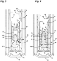
- the figures 3 and 4 have an outer tubular casing 50 arranged around the outer body 2, ending at the bottom with a cover 52.
- a plug 28 comprising an inner part 32 made of a thin sheet metal, forms a cylinder closed below by a base 54, having a large opening at the top comprising an inner rim 60 facing the axis.
- a rod 36 not passing through the assembly of the plug 28 has a lower end fixed to the end cover 18, and a central part passing through the base 54 with a sealed axial guide 38.
- the rod 36 then passes through the second delay chamber 72, its upper end receiving the plug piston 40 sliding in the bore of the inner part 32.
- the plug piston 40 has a calibrated bore 56 for limiting the passage of fluid.
- the top of the first chamber 70 is closed by a valve 58 forming a washer bearing under the internal rim 60, having a calibrated central bore limiting the passage of fluid.
- valve 58 descends by taking off from the internal rim 60, and allows rapid passage of fluid to this first chamber.
- the valve 58 bears under the internal rim 60 with a limited passage of fluid by its central bore.
- the thrust spring 34 is engaged in an axial hollow between the outer part 30 and the inner part 32 of the plug 28, descending to the base 54 in order to be guided downwardly down inside the plug to give a space axial sufficient for this spring when the main piston is at the end of its stroke.
- the return spring 42 is disposed below the base 54, resting on the end cover 18 to apply an upward force continuously on the plug 28.
- the figure 3 shows the thrust spring 34 applying no load or an infrequent load on the plug 28.
- the return spring 42 is relaxed, the plug 28 being in its high position.
- a descent of the plug 28 requires a transfer of fluid from the first chamber 70 to the second delay chamber 72, which is slowed down on the one hand by the calibrated bore 56 of the plug piston 40, and on the other hand by an outlet of the valve. excess fluid from this first chamber by the calibrated drilling of the valve 58, towards the damping chamber 8 because of the rod 36 entering this timing chamber.
- the thrust spring 34 acts little or more on the valve 28.
- the return spring 42 raises the valve 28 with an emptying of the second delay chamber 72 by the calibrated bore of the valve piston 40, and a rapid contribution to the filling of the first chamber 70 by the valve 58 which descends while opening virtually.
- the ascent of the plug 28 can be faster than its descent thanks to the two internal chambers 70, 72 of this plug, which allow a wide possibility of adjustment by adjusting the calibration of the bores of the plug piston 40 and the valve 58.
- the end-of-travel stopper can only comprise main bores on the stopper tube 14, the sleeve 12 not comprising a borehole, or a combination of bores in this tube and in the liner.
- the number, size and distribution of these holes is easily adjustable.
- the telescopic shock absorber comprising the hydraulic stop according to the invention can be placed in the motor vehicle in all directions.
- the shock absorber rod 6 can be connected to the body of the vehicle or vice versa to a suspension element.
Landscapes
- Engineering & Computer Science (AREA)
- General Engineering & Computer Science (AREA)
- Mechanical Engineering (AREA)
- Physics & Mathematics (AREA)
- Fluid Mechanics (AREA)
- Fluid-Damping Devices (AREA)
- Vehicle Body Suspensions (AREA)
Claims (10)
- Teleskopischer hydraulischer Stoßdämpfer mit Endanschlag, entlang einer Hauptachse verschiebbar, umfassend einen während einer Einfederungsbewegung des Stoßdämpfers nach vorne ausfahrenden Dämpfungskolben (4), der vor diesem Dämpfungskolben (4) eine Dämpfung definiert Kammer (8), eine vor dem Dämpfungskolben (4) befestigte Hülse (12), am Hubende spielfrei um ein Anschlagrohr (14) durch Verschließen der ersten Bohrungen (20) der Hülse (12) oder des Stopfenrohres (14), wobei der Stopfen einen in dem Stopfenrohr (14) axial verschiebbaren Stopfen (28) zum Verschließen zweiter Bohrungen (46) dieses Stopfenrohres (14) und eine Druckfeder (34) umfasst zwischen dem Dämpfungskolben (4) und dem Stopfen (28) angeordnet, dadurch gekennzeichnet, dass der Stopfen (28) eine axiale Bohrung aufweist, die einen Stopfenkolben (40) enthält, der hinter einer ersten Kammer (70) definiert, die von der Dämpfungskammer (8) und von vor einer zweiten Kammer (72), die die Bewegung des Ventils (28) verzögert.
- Hydraulischer Stoßdämpfer nach Anspruch 1, dadurch gekennzeichnet, dass er eine Rückstellfeder (42) umfasst, die eine konstante Kraft nach hinten auf das Ventil (28) ausübt.
- Hydraulischer Stoßdämpfer nach Anspruch 1 oder 2, dadurch gekennzeichnet, dass der Ventilkolben (40) eine Bohrung (56) zur Begrenzung des Flüssigkeitsdurchtritts aufweist.
- Hydraulischer Stoßdämpfer nach Anspruch 3, dadurch gekennzeichnet, dass der Ventilkolben (40) an einer Axialstange (36) befestigt ist, die die beiden Kammern des Ventils (70, 72) durchsetzt.
- Hydraulischer Stoßdämpfer nach Anspruch 4, dadurch gekennzeichnet, dass an den gegenüberliegenden axialen Enden der Ventilkammern (70, 72) die axiale Stange (36) das Ventil (28) durch abgedichtete Führungen (38) durchsetzt.
- Hydraulischer Stoßdämpfer nach einem der Ansprüche 1 bis 3, dadurch gekennzeichnet, dass der Steckkolben (40) am Ende einer die zweite Kammer (72) durchsetzenden Axialstange (36) befestigt ist.
- Hydraulischer Stoßdämpfer nach Anspruch 6, dadurch gekennzeichnet, dass das hintere axiale Ende der ersten Kammer (70) durch ein Ventil (58) von der Dämpfungskammer (8) getrennt ist, wodurch eine maximale Öffnung zum Befüllen dieses ersten Schlafzimmers bereitgestellt wird (70).
- Hydraulischer Stoßdämpfer nach Anspruch 7, dadurch gekennzeichnet, dass das Ventil (58) eine Bohrung zur Begrenzung des Flüssigkeitsdurchtritts aufweist.
- Hydraulischer Stoßdämpfer nach einem der vorhergehenden Ansprüche, dadurch gekennzeichnet, dass die Schubfeder (34) nach vorne in eine axiale Vertiefung des Stopfens (28) eingreift, die sich bis zur zweiten Kammer (72) erstreckt.
- Kraftfahrzeug mit Aufhängungen, dadurch gekennzeichnet, dass diese Aufhängungen Stoßdämpfer nach einem der vorhergehenden Ansprüche umfassen.
Applications Claiming Priority (2)
| Application Number | Priority Date | Filing Date | Title |
|---|---|---|---|
| FR1761333A FR3074244B1 (fr) | 2017-11-29 | 2017-11-29 | Amortisseur hydraulique avec butee de fin de course autoreglable suivant la charge |
| PCT/FR2018/052782 WO2019106251A1 (fr) | 2017-11-29 | 2018-11-09 | Amortisseur hydraulique avec butee de fin de course autoreglable suivant la charge |
Publications (2)
| Publication Number | Publication Date |
|---|---|
| EP3717792A1 EP3717792A1 (de) | 2020-10-07 |
| EP3717792B1 true EP3717792B1 (de) | 2021-12-29 |
Family
ID=61027964
Family Applications (1)
| Application Number | Title | Priority Date | Filing Date |
|---|---|---|---|
| EP18867328.9A Active EP3717792B1 (de) | 2017-11-29 | 2018-11-09 | Hydraulischer stossdämpfer mit selbsteinstellbarem lastabhängigem endanschlag |
Country Status (3)
| Country | Link |
|---|---|
| EP (1) | EP3717792B1 (de) |
| FR (1) | FR3074244B1 (de) |
| WO (1) | WO2019106251A1 (de) |
Families Citing this family (4)
| Publication number | Priority date | Publication date | Assignee | Title |
|---|---|---|---|---|
| FR3100298B1 (fr) | 2019-08-28 | 2021-08-06 | Psa Automobiles Sa | Butee hydraulique de suspension de vehicule automobile a masse inertielle |
| ES2832888B2 (es) * | 2019-12-11 | 2022-04-07 | Kyb Europe Gmbh Sucursal En Navarra | Dispositivo de control hidraulico de carga variable |
| WO2024047469A1 (en) * | 2022-08-30 | 2024-03-07 | Way Assauto Srl | Hydraulic shock absorber for a vehicle suspension provided with a hydraulic end stop member operating during the compression stroke of the shock absorber |
| CN116518003B (zh) * | 2023-04-04 | 2025-10-03 | 四川宁江山川机械有限责任公司 | 一种用于车辆减振器液压缓冲机构的阀座 |
Family Cites Families (3)
| Publication number | Priority date | Publication date | Assignee | Title |
|---|---|---|---|---|
| BE359981A (de) * | ||||
| JP4195141B2 (ja) * | 1999-02-08 | 2008-12-10 | 不二ラテックス株式会社 | ショックアブソーバ |
| FR3050000B1 (fr) * | 2016-04-08 | 2018-09-07 | Peugeot Citroen Automobiles Sa | Amortisseur hydraulique equipe d’une butee d’attaque presentant une loi de freinage reglable |
-
2017
- 2017-11-29 FR FR1761333A patent/FR3074244B1/fr not_active Expired - Fee Related
-
2018
- 2018-11-09 EP EP18867328.9A patent/EP3717792B1/de active Active
- 2018-11-09 WO PCT/FR2018/052782 patent/WO2019106251A1/fr not_active Ceased
Also Published As
| Publication number | Publication date |
|---|---|
| FR3074244A1 (fr) | 2019-05-31 |
| FR3074244B1 (fr) | 2019-10-18 |
| EP3717792A1 (de) | 2020-10-07 |
| WO2019106251A1 (fr) | 2019-06-06 |
Similar Documents
| Publication | Publication Date | Title |
|---|---|---|
| EP3406931B1 (de) | Selbstregulierender hydraulischer anschlag für den endanschlag einer schwingungsbewegung | |
| FR3074244B1 (fr) | Amortisseur hydraulique avec butee de fin de course autoreglable suivant la charge | |
| EP4022196B1 (de) | Hydraulischer anschlag für eine kraftfahrzeugaufhängung mit trägheitsmasse | |
| FR3050000A1 (fr) | Amortisseur hydraulique equipe d’une butee d’attaque presentant une loi de freinage reglable | |
| EP2956687B1 (de) | Endlagendämpfung | |
| EP3918226B1 (de) | Hydraulischer anschlag für eine kraftfahrzeugaufhängung mit trägheitsmasse | |
| FR3086985A1 (fr) | Amortisseur hydraulique avec reglage automatique suivant une acceleration radiale | |
| EP1717478A1 (de) | Hydraulisches Anschlagsystem für Kraftfahrzeuge | |
| EP3948011B1 (de) | Fluiddämpfer aufweisend einen selbstanpassenden anschlag mit einem schwimmenden schieber | |
| EP3004683A1 (de) | Stossdämpfer mit hydraulischer endlagendämpfung | |
| EP3861229B1 (de) | Hydraulischer stossdämpfer mit hydraulischer endanschlagsbegrenzung an einer selbst einstellbaren höhe | |
| FR3086359A1 (fr) | Amortisseur hydraulique avec butee hydraulique de fin de course a positionnement auto-ajustable | |
| EP3942196B1 (de) | Fluiddämpfer auweisend einen selbstanpassenden anschlag mit einer kammer vor einem schieber | |
| EP3997356B1 (de) | Hydraulischer endanschlag für einen dämpfer | |
| FR2974609A1 (fr) | Amortisseur hydraulique comprenant une tige coulissant dans un tube | |
| EP3781835B1 (de) | Fluiddämpfer mit flüssigkeitsbasierter trägheitsdämpfung für eine fahrzeugfederung | |
| EP3942195B1 (de) | Fluiddämpfer aufweisend einen selbstanpanssenden anschlag mit öffnungen an der stange | |
| WO2020193883A1 (fr) | Amortisseur avec butee de fin de course equipee d'un clapet de limitation de pression | |
| WO2020169893A1 (fr) | Amortisseur hydraulique equipe d'une butee de fin de course auto-adaptable | |
| FR3122714A1 (fr) | Systeme de butee hydraulique comprenant une bague comportant des moyens d’obstacle a l’ecoulement dans une chambre de compensation | |
| FR2988033A1 (fr) | Amortisseur hydraulique comprenant une butee d'attaque | |
| FR3003619A1 (fr) | Amortisseur hydraulique comportant un dispositif de detente rapide | |
| BE349696A (de) |
Legal Events
| Date | Code | Title | Description |
|---|---|---|---|
| STAA | Information on the status of an ep patent application or granted ep patent |
Free format text: STATUS: UNKNOWN |
|
| STAA | Information on the status of an ep patent application or granted ep patent |
Free format text: STATUS: THE INTERNATIONAL PUBLICATION HAS BEEN MADE |
|
| PUAI | Public reference made under article 153(3) epc to a published international application that has entered the european phase |
Free format text: ORIGINAL CODE: 0009012 |
|
| STAA | Information on the status of an ep patent application or granted ep patent |
Free format text: STATUS: REQUEST FOR EXAMINATION WAS MADE |
|
| 17P | Request for examination filed |
Effective date: 20200615 |
|
| AK | Designated contracting states |
Kind code of ref document: A1 Designated state(s): AL AT BE BG CH CY CZ DE DK EE ES FI FR GB GR HR HU IE IS IT LI LT LU LV MC MK MT NL NO PL PT RO RS SE SI SK SM TR |
|
| AX | Request for extension of the european patent |
Extension state: BA ME |
|
| RAP1 | Party data changed (applicant data changed or rights of an application transferred) |
Owner name: PSA AUTOMOBILES SA |
|
| DAV | Request for validation of the european patent (deleted) | ||
| DAX | Request for extension of the european patent (deleted) | ||
| GRAP | Despatch of communication of intention to grant a patent |
Free format text: ORIGINAL CODE: EPIDOSNIGR1 |
|
| STAA | Information on the status of an ep patent application or granted ep patent |
Free format text: STATUS: GRANT OF PATENT IS INTENDED |
|
| INTG | Intention to grant announced |
Effective date: 20210726 |
|
| GRAS | Grant fee paid |
Free format text: ORIGINAL CODE: EPIDOSNIGR3 |
|
| GRAA | (expected) grant |
Free format text: ORIGINAL CODE: 0009210 |
|
| STAA | Information on the status of an ep patent application or granted ep patent |
Free format text: STATUS: THE PATENT HAS BEEN GRANTED |
|
| AK | Designated contracting states |
Kind code of ref document: B1 Designated state(s): AL AT BE BG CH CY CZ DE DK EE ES FI FR GB GR HR HU IE IS IT LI LT LU LV MC MK MT NL NO PL PT RO RS SE SI SK SM TR |
|
| REG | Reference to a national code |
Ref country code: GB Ref legal event code: FG4D Free format text: NOT ENGLISH |
|
| REG | Reference to a national code |
Ref country code: CH Ref legal event code: EP |
|
| REG | Reference to a national code |
Ref country code: DE Ref legal event code: R084 Ref document number: 602018028961 Country of ref document: DE |
|
| REG | Reference to a national code |
Ref country code: AT Ref legal event code: REF Ref document number: 1458908 Country of ref document: AT Kind code of ref document: T Effective date: 20220115 |
|
| REG | Reference to a national code |
Ref country code: IE Ref legal event code: FG4D Free format text: LANGUAGE OF EP DOCUMENT: FRENCH |
|
| REG | Reference to a national code |
Ref country code: DE Ref legal event code: R096 Ref document number: 602018028961 Country of ref document: DE |
|
| REG | Reference to a national code |
Ref country code: GB Ref legal event code: 746 Effective date: 20220131 |
|
| REG | Reference to a national code |
Ref country code: LT Ref legal event code: MG9D |
|
| PG25 | Lapsed in a contracting state [announced via postgrant information from national office to epo] |
Ref country code: RS Free format text: LAPSE BECAUSE OF FAILURE TO SUBMIT A TRANSLATION OF THE DESCRIPTION OR TO PAY THE FEE WITHIN THE PRESCRIBED TIME-LIMIT Effective date: 20211229 Ref country code: LT Free format text: LAPSE BECAUSE OF FAILURE TO SUBMIT A TRANSLATION OF THE DESCRIPTION OR TO PAY THE FEE WITHIN THE PRESCRIBED TIME-LIMIT Effective date: 20211229 Ref country code: FI Free format text: LAPSE BECAUSE OF FAILURE TO SUBMIT A TRANSLATION OF THE DESCRIPTION OR TO PAY THE FEE WITHIN THE PRESCRIBED TIME-LIMIT Effective date: 20211229 Ref country code: BG Free format text: LAPSE BECAUSE OF FAILURE TO SUBMIT A TRANSLATION OF THE DESCRIPTION OR TO PAY THE FEE WITHIN THE PRESCRIBED TIME-LIMIT Effective date: 20220329 |
|
| REG | Reference to a national code |
Ref country code: NL Ref legal event code: MP Effective date: 20211229 |
|
| REG | Reference to a national code |
Ref country code: AT Ref legal event code: MK05 Ref document number: 1458908 Country of ref document: AT Kind code of ref document: T Effective date: 20211229 |
|
| PG25 | Lapsed in a contracting state [announced via postgrant information from national office to epo] |
Ref country code: SE Free format text: LAPSE BECAUSE OF FAILURE TO SUBMIT A TRANSLATION OF THE DESCRIPTION OR TO PAY THE FEE WITHIN THE PRESCRIBED TIME-LIMIT Effective date: 20211229 Ref country code: NO Free format text: LAPSE BECAUSE OF FAILURE TO SUBMIT A TRANSLATION OF THE DESCRIPTION OR TO PAY THE FEE WITHIN THE PRESCRIBED TIME-LIMIT Effective date: 20220329 Ref country code: LV Free format text: LAPSE BECAUSE OF FAILURE TO SUBMIT A TRANSLATION OF THE DESCRIPTION OR TO PAY THE FEE WITHIN THE PRESCRIBED TIME-LIMIT Effective date: 20211229 Ref country code: HR Free format text: LAPSE BECAUSE OF FAILURE TO SUBMIT A TRANSLATION OF THE DESCRIPTION OR TO PAY THE FEE WITHIN THE PRESCRIBED TIME-LIMIT Effective date: 20211229 Ref country code: GR Free format text: LAPSE BECAUSE OF FAILURE TO SUBMIT A TRANSLATION OF THE DESCRIPTION OR TO PAY THE FEE WITHIN THE PRESCRIBED TIME-LIMIT Effective date: 20220330 |
|
| PG25 | Lapsed in a contracting state [announced via postgrant information from national office to epo] |
Ref country code: NL Free format text: LAPSE BECAUSE OF FAILURE TO SUBMIT A TRANSLATION OF THE DESCRIPTION OR TO PAY THE FEE WITHIN THE PRESCRIBED TIME-LIMIT Effective date: 20211229 |
|
| PG25 | Lapsed in a contracting state [announced via postgrant information from national office to epo] |
Ref country code: SM Free format text: LAPSE BECAUSE OF FAILURE TO SUBMIT A TRANSLATION OF THE DESCRIPTION OR TO PAY THE FEE WITHIN THE PRESCRIBED TIME-LIMIT Effective date: 20211229 Ref country code: SK Free format text: LAPSE BECAUSE OF FAILURE TO SUBMIT A TRANSLATION OF THE DESCRIPTION OR TO PAY THE FEE WITHIN THE PRESCRIBED TIME-LIMIT Effective date: 20211229 Ref country code: RO Free format text: LAPSE BECAUSE OF FAILURE TO SUBMIT A TRANSLATION OF THE DESCRIPTION OR TO PAY THE FEE WITHIN THE PRESCRIBED TIME-LIMIT Effective date: 20211229 Ref country code: PT Free format text: LAPSE BECAUSE OF FAILURE TO SUBMIT A TRANSLATION OF THE DESCRIPTION OR TO PAY THE FEE WITHIN THE PRESCRIBED TIME-LIMIT Effective date: 20220429 Ref country code: ES Free format text: LAPSE BECAUSE OF FAILURE TO SUBMIT A TRANSLATION OF THE DESCRIPTION OR TO PAY THE FEE WITHIN THE PRESCRIBED TIME-LIMIT Effective date: 20211229 Ref country code: EE Free format text: LAPSE BECAUSE OF FAILURE TO SUBMIT A TRANSLATION OF THE DESCRIPTION OR TO PAY THE FEE WITHIN THE PRESCRIBED TIME-LIMIT Effective date: 20211229 Ref country code: CZ Free format text: LAPSE BECAUSE OF FAILURE TO SUBMIT A TRANSLATION OF THE DESCRIPTION OR TO PAY THE FEE WITHIN THE PRESCRIBED TIME-LIMIT Effective date: 20211229 |
|
| PG25 | Lapsed in a contracting state [announced via postgrant information from national office to epo] |
Ref country code: PL Free format text: LAPSE BECAUSE OF FAILURE TO SUBMIT A TRANSLATION OF THE DESCRIPTION OR TO PAY THE FEE WITHIN THE PRESCRIBED TIME-LIMIT Effective date: 20211229 Ref country code: AT Free format text: LAPSE BECAUSE OF FAILURE TO SUBMIT A TRANSLATION OF THE DESCRIPTION OR TO PAY THE FEE WITHIN THE PRESCRIBED TIME-LIMIT Effective date: 20211229 |
|
| PG25 | Lapsed in a contracting state [announced via postgrant information from national office to epo] |
Ref country code: IS Free format text: LAPSE BECAUSE OF FAILURE TO SUBMIT A TRANSLATION OF THE DESCRIPTION OR TO PAY THE FEE WITHIN THE PRESCRIBED TIME-LIMIT Effective date: 20220429 |
|
| REG | Reference to a national code |
Ref country code: DE Ref legal event code: R097 Ref document number: 602018028961 Country of ref document: DE |
|
| PG25 | Lapsed in a contracting state [announced via postgrant information from national office to epo] |
Ref country code: DK Free format text: LAPSE BECAUSE OF FAILURE TO SUBMIT A TRANSLATION OF THE DESCRIPTION OR TO PAY THE FEE WITHIN THE PRESCRIBED TIME-LIMIT Effective date: 20211229 Ref country code: AL Free format text: LAPSE BECAUSE OF FAILURE TO SUBMIT A TRANSLATION OF THE DESCRIPTION OR TO PAY THE FEE WITHIN THE PRESCRIBED TIME-LIMIT Effective date: 20211229 |
|
| PLBE | No opposition filed within time limit |
Free format text: ORIGINAL CODE: 0009261 |
|
| STAA | Information on the status of an ep patent application or granted ep patent |
Free format text: STATUS: NO OPPOSITION FILED WITHIN TIME LIMIT |
|
| 26N | No opposition filed |
Effective date: 20220930 |
|
| PG25 | Lapsed in a contracting state [announced via postgrant information from national office to epo] |
Ref country code: SI Free format text: LAPSE BECAUSE OF FAILURE TO SUBMIT A TRANSLATION OF THE DESCRIPTION OR TO PAY THE FEE WITHIN THE PRESCRIBED TIME-LIMIT Effective date: 20211229 |
|
| PG25 | Lapsed in a contracting state [announced via postgrant information from national office to epo] |
Ref country code: IT Free format text: LAPSE BECAUSE OF FAILURE TO SUBMIT A TRANSLATION OF THE DESCRIPTION OR TO PAY THE FEE WITHIN THE PRESCRIBED TIME-LIMIT Effective date: 20211229 |
|
| PG25 | Lapsed in a contracting state [announced via postgrant information from national office to epo] |
Ref country code: MC Free format text: LAPSE BECAUSE OF FAILURE TO SUBMIT A TRANSLATION OF THE DESCRIPTION OR TO PAY THE FEE WITHIN THE PRESCRIBED TIME-LIMIT Effective date: 20211229 |
|
| REG | Reference to a national code |
Ref country code: CH Ref legal event code: PL |
|
| REG | Reference to a national code |
Ref country code: BE Ref legal event code: MM Effective date: 20221130 |
|
| PG25 | Lapsed in a contracting state [announced via postgrant information from national office to epo] |
Ref country code: LI Free format text: LAPSE BECAUSE OF NON-PAYMENT OF DUE FEES Effective date: 20221130 Ref country code: CH Free format text: LAPSE BECAUSE OF NON-PAYMENT OF DUE FEES Effective date: 20221130 |
|
| PG25 | Lapsed in a contracting state [announced via postgrant information from national office to epo] |
Ref country code: LU Free format text: LAPSE BECAUSE OF NON-PAYMENT OF DUE FEES Effective date: 20221109 |
|
| PG25 | Lapsed in a contracting state [announced via postgrant information from national office to epo] |
Ref country code: IE Free format text: LAPSE BECAUSE OF NON-PAYMENT OF DUE FEES Effective date: 20221109 |
|
| PG25 | Lapsed in a contracting state [announced via postgrant information from national office to epo] |
Ref country code: BE Free format text: LAPSE BECAUSE OF NON-PAYMENT OF DUE FEES Effective date: 20221130 |
|
| PGFP | Annual fee paid to national office [announced via postgrant information from national office to epo] |
Ref country code: GB Payment date: 20231019 Year of fee payment: 6 |
|
| REG | Reference to a national code |
Ref country code: DE Ref legal event code: R081 Ref document number: 602018028961 Country of ref document: DE Owner name: STELLANTIS AUTO SAS, FR Free format text: FORMER OWNER: PSA AUTOMOBILES SA, POISSY, FR |
|
| PG25 | Lapsed in a contracting state [announced via postgrant information from national office to epo] |
Ref country code: CY Free format text: LAPSE BECAUSE OF FAILURE TO SUBMIT A TRANSLATION OF THE DESCRIPTION OR TO PAY THE FEE WITHIN THE PRESCRIBED TIME-LIMIT Effective date: 20211229 |
|
| PG25 | Lapsed in a contracting state [announced via postgrant information from national office to epo] |
Ref country code: MK Free format text: LAPSE BECAUSE OF FAILURE TO SUBMIT A TRANSLATION OF THE DESCRIPTION OR TO PAY THE FEE WITHIN THE PRESCRIBED TIME-LIMIT Effective date: 20211229 Ref country code: HU Free format text: LAPSE BECAUSE OF FAILURE TO SUBMIT A TRANSLATION OF THE DESCRIPTION OR TO PAY THE FEE WITHIN THE PRESCRIBED TIME-LIMIT; INVALID AB INITIO Effective date: 20181109 |
|
| PG25 | Lapsed in a contracting state [announced via postgrant information from national office to epo] |
Ref country code: TR Free format text: LAPSE BECAUSE OF FAILURE TO SUBMIT A TRANSLATION OF THE DESCRIPTION OR TO PAY THE FEE WITHIN THE PRESCRIBED TIME-LIMIT Effective date: 20211229 |
|
| PG25 | Lapsed in a contracting state [announced via postgrant information from national office to epo] |
Ref country code: MT Free format text: LAPSE BECAUSE OF FAILURE TO SUBMIT A TRANSLATION OF THE DESCRIPTION OR TO PAY THE FEE WITHIN THE PRESCRIBED TIME-LIMIT Effective date: 20211229 |
|
| GBPC | Gb: european patent ceased through non-payment of renewal fee |
Effective date: 20241109 |
|
| PG25 | Lapsed in a contracting state [announced via postgrant information from national office to epo] |
Ref country code: GB Free format text: LAPSE BECAUSE OF NON-PAYMENT OF DUE FEES Effective date: 20241109 |
|
| PGFP | Annual fee paid to national office [announced via postgrant information from national office to epo] |
Ref country code: DE Payment date: 20251022 Year of fee payment: 8 |
|
| PGFP | Annual fee paid to national office [announced via postgrant information from national office to epo] |
Ref country code: FR Payment date: 20251022 Year of fee payment: 8 |