EP3717833B1 - A method of reduction of nitrogen oxides and carbon monoxide in furnace chambers of water boilers and steam boilers, especially grate boilers, and a system for reduction of nitrogen oxides and carbon monoxide in furnace chambers of water boilers and steam boilers, especially grate boilers. - Google Patents
A method of reduction of nitrogen oxides and carbon monoxide in furnace chambers of water boilers and steam boilers, especially grate boilers, and a system for reduction of nitrogen oxides and carbon monoxide in furnace chambers of water boilers and steam boilers, especially grate boilers. Download PDFInfo
- Publication number
- EP3717833B1 EP3717833B1 EP18822516.3A EP18822516A EP3717833B1 EP 3717833 B1 EP3717833 B1 EP 3717833B1 EP 18822516 A EP18822516 A EP 18822516A EP 3717833 B1 EP3717833 B1 EP 3717833B1
- Authority
- EP
- European Patent Office
- Prior art keywords
- furnace chamber
- process gas
- lances
- reactant
- injection
- Prior art date
- Legal status (The legal status is an assumption and is not a legal conclusion. Google has not performed a legal analysis and makes no representation as to the accuracy of the status listed.)
- Active
Links
Images







Classifications
-
- F—MECHANICAL ENGINEERING; LIGHTING; HEATING; WEAPONS; BLASTING
- F23—COMBUSTION APPARATUS; COMBUSTION PROCESSES
- F23L—SUPPLYING AIR OR NON-COMBUSTIBLE LIQUIDS OR GASES TO COMBUSTION APPARATUS IN GENERAL ; VALVES OR DAMPERS SPECIALLY ADAPTED FOR CONTROLLING AIR SUPPLY OR DRAUGHT IN COMBUSTION APPARATUS; INDUCING DRAUGHT IN COMBUSTION APPARATUS; TOPS FOR CHIMNEYS OR VENTILATING SHAFTS; TERMINALS FOR FLUES
- F23L7/00—Supplying non-combustible liquids or gases, other than air, to the fire, e.g. oxygen, steam
-
- B—PERFORMING OPERATIONS; TRANSPORTING
- B01—PHYSICAL OR CHEMICAL PROCESSES OR APPARATUS IN GENERAL
- B01D—SEPARATION
- B01D53/00—Separation of gases or vapours; Recovering vapours of volatile solvents from gases; Chemical or biological purification of waste gases, e.g. engine exhaust gases, smoke, fumes, flue gases, aerosols
- B01D53/34—Chemical or biological purification of waste gases
- B01D53/46—Removing components of defined structure
- B01D53/54—Nitrogen compounds
- B01D53/56—Nitrogen oxides
-
- B—PERFORMING OPERATIONS; TRANSPORTING
- B01—PHYSICAL OR CHEMICAL PROCESSES OR APPARATUS IN GENERAL
- B01D—SEPARATION
- B01D53/00—Separation of gases or vapours; Recovering vapours of volatile solvents from gases; Chemical or biological purification of waste gases, e.g. engine exhaust gases, smoke, fumes, flue gases, aerosols
- B01D53/34—Chemical or biological purification of waste gases
- B01D53/74—General processes for purification of waste gases; Apparatus or devices specially adapted therefor
- B01D53/77—Liquid phase processes
- B01D53/79—Injecting reactants
-
- F—MECHANICAL ENGINEERING; LIGHTING; HEATING; WEAPONS; BLASTING
- F23—COMBUSTION APPARATUS; COMBUSTION PROCESSES
- F23J—REMOVAL OR TREATMENT OF COMBUSTION PRODUCTS OR COMBUSTION RESIDUES; FLUES
- F23J7/00—Arrangement of devices for supplying chemicals to fire
-
- B—PERFORMING OPERATIONS; TRANSPORTING
- B01—PHYSICAL OR CHEMICAL PROCESSES OR APPARATUS IN GENERAL
- B01D—SEPARATION
- B01D2251/00—Reactants
- B01D2251/20—Reductants
- B01D2251/206—Ammonium compounds
- B01D2251/2062—Ammonia
-
- B—PERFORMING OPERATIONS; TRANSPORTING
- B01—PHYSICAL OR CHEMICAL PROCESSES OR APPARATUS IN GENERAL
- B01D—SEPARATION
- B01D2251/00—Reactants
- B01D2251/20—Reductants
- B01D2251/206—Ammonium compounds
- B01D2251/2067—Urea
-
- B—PERFORMING OPERATIONS; TRANSPORTING
- B01—PHYSICAL OR CHEMICAL PROCESSES OR APPARATUS IN GENERAL
- B01D—SEPARATION
- B01D2257/00—Components to be removed
- B01D2257/40—Nitrogen compounds
- B01D2257/404—Nitrogen oxides other than dinitrogen oxide
-
- B—PERFORMING OPERATIONS; TRANSPORTING
- B01—PHYSICAL OR CHEMICAL PROCESSES OR APPARATUS IN GENERAL
- B01D—SEPARATION
- B01D2258/00—Sources of waste gases
- B01D2258/02—Other waste gases
- B01D2258/0283—Flue gases
-
- F—MECHANICAL ENGINEERING; LIGHTING; HEATING; WEAPONS; BLASTING
- F23—COMBUSTION APPARATUS; COMBUSTION PROCESSES
- F23J—REMOVAL OR TREATMENT OF COMBUSTION PRODUCTS OR COMBUSTION RESIDUES; FLUES
- F23J2215/00—Preventing emissions
- F23J2215/10—Nitrogen; Compounds thereof
Definitions
- the subject of the invention is a method of reduction of nitrogen oxides and carbon monoxide in furnace chambers of water boilers and steam boilers, especially grate boilers, and a water and steam boiler with a system for reduction of nitrogen oxides and carbon monoxide in the furnace chamber, which system is also applicable to the reduction of generation of nitrogen oxides and carbon monoxide and/or their reduction in combustion chambers of heating boilers and power boilers, especially grate boilers.
- the method described in the patent No. WO 2004/085922 A2 assumes the reduction of NOx emissions by using the method of primary reduction of toxic compounds that consists in dividing the combustion air stream.
- a part of the air is supplied near the fuel supply as primary air, and the remaining part of air necessary for a complete and perfect combustion of the fuel is fed above the fuel supply point, in higher parts of the combustion area, by means of nozzles located on the walls of the combustion chamber, the air stream fed in this area forms a vortex that is parallel to or close to the plane perpendicular to the vertical axis of the combustion chamber.
- WO 92/02290 A1 discloses a method and apparatus for reducing nitrogen oxides in the flue gas from a boiler furnace.
- the nitrogen oxides are reduced by injecting an ammonia-containing treatment gas comprising a carrier gas into the flue gas.
- Elimination of the above inconveniences and limitations with the guarantee of: further reduction of NO x emissions, reduction of CO emission, reduction to a minimum or complete elimination of the reactant in flue gas and ash, increase in system efficiency by limiting the proportion of oxygen in the flue gas, and reduction of investment outlays and operating costs in comparison with known methods of NO x reduction and CO emission reduction, can be achieved by a method according to the present invention.
- a reactant preferably NH 3 or CO(NH 2 ) 2
- a reactant may be injected into the furnace chamber in a manner analogous to the process gas, by means of process gas lances or additional lances.
- a water and steam boiler especially a grate boiler, comprising a furnace chamber and a system for the reduction of nitrogen oxides and carbon monoxide is provided as set out in claim 7.
- the process gas lances are located on the front wall of the furnace chamber in a specially made panel wall deflection at one, two or three levels, and the process gas is injected in a direction opposite to the main, natural flow direction of products / semi-products of the combustion process, maintaining a deviation of +/-15° in the plane parallel to the longitudinal symmetry plane of the furnace chamber, the injection points from the highest level of lances being at a distance of 0.5 to 1 height of the furnace chamber above the grate, preferably at the level of the lower edge of the bull nose, and the remaining rows below them.
- the process gas lances are placed on the front or/and on the side wall of the furnace chamber at one, two or three levels, and the process gas is introduced into the furnace chamber by means of lances similar in their shape to the letter "L", in the direction opposite to the main, natural flow direction of the products / semi-products of the combustion process, maintaining a stream deviation of +/-15°, in a plane parallel to the longitudinal symmetry plane of the furnace chamber, the injection points from the highest level of lances being at a distance of 0.5 to 1 height of the furnace chamber above the grate, preferably at the level of the lower edge of the bull nose, and the remaining rows below.
- a mixture of process gas and reactant is injected into the furnace chamber through the same lances and at the same speed as the process gas, i.e. from 30 to 180 m/s, preferably 135 m/s, the reactant being injected through a reactant feed consisting of a reservoir, a pump, a flow regulator, a flow meter and at least one lance, into the process gas collector in a central manner through at least one lance, in order to form a homogeneous mixture therein, whereas in the convection part of the boiler or behind it, a device measuring NOx concentration in the flue gas is built in, from which the signal is sent to the control device, which in turn controls the reactant flow rate through the actuating and measuring devices built on this installation.
- the reactant in form of a liquid, gas or gas-liquid mixture is injected into the furnace chamber through nozzles located coaxially in the process gas lances, the number of reactant nozzles being equal to or smaller than the number of process gas lances.
- the reactant in form of a liquid, gas or gas-liquid mixture is injected into the furnace chamber through nozzles located eccentrically in the process gas lances, the number of reactant nozzles being equal to or smaller than the number of process gas lances.
- the reactant in form of a liquid, gas or gas-liquid mixture is injected into furnace chamber through the lances located between the process gas lances, the number of reactant lances being equal to or smaller than the number of process gas lances.
- the process gas lances are located on the back wall of the furnace chamber at the level of the lower edge of the furnace chamber bull nose, i.e. at the connection point of the furnace chamber with the boiler convection draught, in a number of from a few up to a dozen or so, depending on the size of the furnace chamber, the process gas being supplied through these lances in the horizontal direction, with maintaining a stream deviation of +/-45°, in an amount of up to 20%, preferably 10% of the air stream supplied to the device, necessary to completely and perfectly burn the fuel, in the understanding of accepted standards for this type of devices, with maintaining or reducing the proportion of oxygen in the flue gas.
- the process gas is injected into the furnace chamber of the device through the lances installed on the back wall of the furnace chamber, as described in one of the above variants, while the reactant in form of a liquid, gas or gas-iiquid mixture and a part of the air in an amount of up to 5% of the air stream supplied to the furnace chamber, are injected into the furnace chamber through lances installed at one, two or three levels from the opposite wall of the furnace chamber in a direction opposite to the direction of the main, natural flow of combustion process products/semi-products flowing through the furnace chamber of the device, maintaining the stream deviation of +/-15°.
- the process gas is introduced into the combustion chamber through the lances located at a level different from the reactant feed level.
- the amount of media flowing through the lances may vary for individual lances depending on the boiler load, in order to balance the temperature profiles in the furnace chamber and to shape the reduction and oxidation zone.
- a part of the lances may be switched off in order to balance the temperature profiles in the furnace chamber and to shape the reduction and oxidation zone.
- the dynamic effect of the process gas stream is used to intensify the mixing process in the furnace chamber by causing a strong internal flue gas recirculation and strong swirl therein, the direction of which is opposite to the main, natural flue gas flow direction, and the spinning plane is parallel to the longitudinal plane of symmetry of the furnace chamber.
- the solution according to the method makes possible a precise temperature control in the furnace chamber in the area where the phenomenon of reduction of nitrogen oxides and CO afterburning occurs, reduces the concentration of the reactant in the furnace chamber, minimizing the risk of corrosion of the device parts, moreover, the invention according to one of variants, by deploying the lances at several levels of the furnace chamber, increases the possibilities of the system, in particular in a wide scope of boiler load variability and it is usually applied in units of higher power.
- the invention according to the method also limits the reactant consumption in comparison to the methods known up to now, and thus makes possible to minimize the content of unreacted reactant in ash or flue gas, which plays a very important role in terms of system operating costs, environmental protection and ash management.
- Such a method of feeding the process gas or process gas and reactant results in creation of a strong reverse internal recirculation vortex, which sucks in the flue gas from the main flue gas stream, from the area just before the connection of the furnace chamber with the convection draught, and thus creates optimal conditions for conducting the process of reduction of nitrogen oxides and post-combustion of carbon monoxide, with a minimum proportion of oxygen in the final flue gas, and minimizes the loss of the reactant into the chimney due to the fact that the reactant injection point is located away from the flue gas exit point from the furnace chamber, which protects the system from the "entrainment" of unreacted, only just injected reactant particles into the convection draught of the boiler, moreover, the opposite direction of injection of the reagent, towards the temperature increase in the furnace chamber, and strong internal recirculation give the time necessary for mixing the reactant with the process gas and the flue gas, which results in creation of a homogeneous mixture, and thus contributes to short
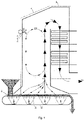
- FIG. 1 The block diagram of a system for the injection of process gas and reactant into a furnace chamber is shown in figure 1 , where: 6 - means the process gas injection lance, 7 - means the reactant injection lance/nozzle, 10 - means the furnace chamber of the device, 11 - means the process gas intake, 12 - means the process gas fan, 13 - means the measuring system installed on the process gas collector, 14 - means the regulating and shut-off element installed on the process gas collector, 15 - means the reactant tank, 16 - means the reactant pump, 17- means the measuring system built on the reactant installation, 18 - means the regulating and shut-off element built on the reactant installation, 19 - means the central injection lance of the reactant into the process gas.
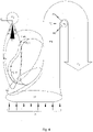
- FIGS. 2 , 3 and 4 the processes occurring during combustion in the furnace chamber of the device, preferably a grate boiler, and the main flow and rotation directions of the process gas, flue gas and reactant are schematically and visually shown, where: A - means the blast (primary) air stream, PG - means the process gas stream, R - means the reactant stream, FG - means the flue gas stream, iFGR - means the internal flue gas recirculation, PG + R - defines the area of occurrence of the process gas and reactant mixture, RZ - defines the area in which the reduction reaction takes place, PZ - defines the production area of nitrogen compounds, CZ - defines the main combustion area.
- a - means the blast (primary) air stream
- PG - means the process gas stream
- R - means the reactant stream
- FG - means the flue gas stream
- iFGR - means the internal flue gas recirculation
- PG + R - defines the area of
- FIG. 5 , 6 , 7 , 8 and 9 a schematic and visual representation of the place of installation of process gas and reactant injection lances is shown, as well as the current lines and spin directions that arise during combustion in the furnace chamber of the device, preferably a grate boiler, where: 1 - means the under-grate air-box, 2 - means the fuel layer moving on the grate, 3 - means the grate, 4 - means the furnace chamber, 5 - means the process gas / reactant collector, 6 - means the injection lance of the process gas, 7 - means the reactant injection lance/nozzle, 8 - means the convection part of the boiler, 9 - means the process gas collector, A - means the blast (primary) air stream, PG - means the process gas stream, PG+R - means the process gas and reactant stream, FG - means flue gas stream, iFGR - means the internal flue gas recirculation.
- 1 - means the under-grate air-box
- FIG. 7 An exemplary embodiment of a water and steam boiler according to the invention is shown in fig. 7 , where A means the primary air forced by the blast fan to the regulating slide dampers and then into the under-grate boxes 1 whose task is to bring the oxidant in a controlled manner to the fuel 2 moving on the grate 3 .
- A means the primary air forced by the blast fan to the regulating slide dampers and then into the under-grate boxes 1 whose task is to bring the oxidant in a controlled manner to the fuel 2 moving on the grate 3 .
- the fuel is combusted and the amount of oxidant supplied as the primary air A ranges from 0.7 to 1.1, preferably 0.9 of the stoichiometric amount of air needed for complete and perfect combustion of fuel 2 moving on the grate 3 , in the meaning of standards for this type of device.
- the injection speed of the process gas PG or reactant R is from 30 up to 180 m/s, preferably 135 m/s, and the process gas stream is up to 20% of the air stream necessary for complete and perfect combustion of fuel in the meaning of the standards for this type of device, a high speed and a significant mass of the process gas stream causes a strong internal recirculation of the flue gas iFGR in the interior of the combustion chamber 4 and the creation of a strong reverse vortex in the plane parallel to the longitudinal symmetry plane of the furnace chamber.
- the lances 6 and 7 are formed in a shape similar to the letter "L" and are introduced through deflections made in the front wall of the furnace chamber 10 .
- the method of attaching the lances 6 and 7 enables their position to be changed in a plane parallel to the longitudinal symmetry plane of the boiler by a value of +/-15°.
- This method of feeding the process gas PG and reagent R is favourable for the creation of conditions for conducting the process of reducing nitrogen oxides with very high efficiency due to the point of injection of the reactant being away from the place of flue gas exit from the furnace chamber 4, which protects the system from the entrainment of unreacted reactant particles into the boiler convection draught 8, the reactant is mixed with the injected process gas and combustion products, moving towards a temperature increase, i.e.
- the process gas and reactant feed by the method according to the invention results in the creation of a strong reverse vortex parallel to the longitudinal symmetry plane of the combustion chamber, which makes the system in a wide spectrum of operation a self-regulating system, and thus self-protecting one against the penetration of unreacted reactant to flue gas and ashes, moreover, the system according to the invention is not very sensitive to fluctuations in the amount of nitrogen oxides generated in the fuel combustion process on the grate.
- the invention is applicable wherever emphasis is placed on the high quality of the combustion process, low emissivity especially of nitrogen oxides and carbon monoxide, investment savings, energy saving, and reactant savings, i.e. operating costs.
- the method according to the invention which is illustrated in the description, has been used in heating boilers and power boilers, in particular in grate boilers.
Landscapes
- Engineering & Computer Science (AREA)
- Chemical & Material Sciences (AREA)
- Environmental & Geological Engineering (AREA)
- General Chemical & Material Sciences (AREA)
- Biomedical Technology (AREA)
- Analytical Chemistry (AREA)
- Health & Medical Sciences (AREA)
- Oil, Petroleum & Natural Gas (AREA)
- Chemical Kinetics & Catalysis (AREA)
- Mechanical Engineering (AREA)
- General Engineering & Computer Science (AREA)
- Combustion & Propulsion (AREA)
- Investigating Or Analyzing Non-Biological Materials By The Use Of Chemical Means (AREA)
Applications Claiming Priority (2)
| Application Number | Priority Date | Filing Date | Title |
|---|---|---|---|
| PL423576A PL243551B1 (pl) | 2017-11-24 | 2017-11-24 | Sposób redukcji tlenków azotu oraz tlenku węgla w komorach paleniskowych kotłów wodnych i kotłów parowych, szczególnie kotłów rusztowych oraz układ do redukcji tlenków azotu i tlenku węgla w komorach paleniskowych kotłów wodnych i kotłów parowych, szczególnie kotłów rusztowych |
| PCT/PL2018/000114 WO2019103633A1 (en) | 2017-11-24 | 2018-11-21 | A method of reduction of nitrogen oxides and carbon monoxide in furnace chambers of water boilers and steam boilers, especially grate boilers, and a system for reduction of nitrogen oxides and carbon monoxide in furnace chambers of water boilers and steam boilers, especially grate boilers. |
Publications (2)
| Publication Number | Publication Date |
|---|---|
| EP3717833A1 EP3717833A1 (en) | 2020-10-07 |
| EP3717833B1 true EP3717833B1 (en) | 2022-09-21 |
Family
ID=64746609
Family Applications (1)
| Application Number | Title | Priority Date | Filing Date |
|---|---|---|---|
| EP18822516.3A Active EP3717833B1 (en) | 2017-11-24 | 2018-11-21 | A method of reduction of nitrogen oxides and carbon monoxide in furnace chambers of water boilers and steam boilers, especially grate boilers, and a system for reduction of nitrogen oxides and carbon monoxide in furnace chambers of water boilers and steam boilers, especially grate boilers. |
Country Status (4)
| Country | Link |
|---|---|
| EP (1) | EP3717833B1 (da) |
| DK (1) | DK3717833T3 (da) |
| PL (1) | PL243551B1 (da) |
| WO (1) | WO2019103633A1 (da) |
Families Citing this family (1)
| Publication number | Priority date | Publication date | Assignee | Title |
|---|---|---|---|---|
| CN121155350B (zh) * | 2025-11-19 | 2026-02-27 | 河北耀一节能设备制造有限责任公司 | 一种连续式隧道爆破烟气脱硫脱硝一体机 |
Citations (3)
| Publication number | Priority date | Publication date | Assignee | Title |
|---|---|---|---|---|
| WO1992002290A1 (en) * | 1990-07-27 | 1992-02-20 | Aalborg Ciserv International A/S | Method and apparatus for reducing the contents of nitrogen oxides in combustion effluent gas |
| WO2013055285A1 (en) * | 2011-10-12 | 2013-04-18 | Ecomb Ab (Publ) | Combustion chamber supply device and method thereof |
| US20160003473A1 (en) * | 2014-07-04 | 2016-01-07 | Alstom Technology Ltd | BOILER AND A METHOD FOR NOx EMISSION CONTROL FROM A BOILER |
Family Cites Families (8)
| Publication number | Priority date | Publication date | Assignee | Title |
|---|---|---|---|---|
| CA1097487A (en) * | 1976-04-20 | 1981-03-17 | David W. Turner | Method and apparatus for reducing no.sub.x emission to the atmosphere |
| DE3038875C2 (de) * | 1980-10-15 | 1990-05-31 | Vereinigte Kesselwerke AG, 4000 Düsseldorf | Müllverbrennungsanlage |
| DE3716088A1 (de) * | 1987-04-09 | 1989-02-02 | Muellverbrennungsanlage Wupper | Verfahren zum verbrennen insbesondere von muell |
| SE502283C2 (sv) | 1993-12-03 | 1995-09-25 | Ulf Hagstroem | Sätt och tillförseldon för att reglera blandningsförhållanden i en förbrännings- eller förgasningsanläggning |
| SE515645C2 (sv) | 2000-01-14 | 2001-09-17 | Ecomb Ab | Kameraförsett tillförseldon för en fluid till en förbränningskammare |
| US20040185401A1 (en) | 2003-03-19 | 2004-09-23 | Goran Moberg | Mixing process for combustion furnaces |
| US6988454B2 (en) | 2003-09-09 | 2006-01-24 | Advanced Combustion Technology | Method and apparatus for adding reducing agent to secondary overfire air stream |
| US9120898B2 (en) | 2011-07-08 | 2015-09-01 | Baker Hughes Incorporated | Method of curing thermoplastic polymer for shape memory material |
-
2017
- 2017-11-24 PL PL423576A patent/PL243551B1/pl unknown
-
2018
- 2018-11-21 DK DK18822516.3T patent/DK3717833T3/da active
- 2018-11-21 WO PCT/PL2018/000114 patent/WO2019103633A1/en not_active Ceased
- 2018-11-21 EP EP18822516.3A patent/EP3717833B1/en active Active
Patent Citations (3)
| Publication number | Priority date | Publication date | Assignee | Title |
|---|---|---|---|---|
| WO1992002290A1 (en) * | 1990-07-27 | 1992-02-20 | Aalborg Ciserv International A/S | Method and apparatus for reducing the contents of nitrogen oxides in combustion effluent gas |
| WO2013055285A1 (en) * | 2011-10-12 | 2013-04-18 | Ecomb Ab (Publ) | Combustion chamber supply device and method thereof |
| US20160003473A1 (en) * | 2014-07-04 | 2016-01-07 | Alstom Technology Ltd | BOILER AND A METHOD FOR NOx EMISSION CONTROL FROM A BOILER |
Also Published As
| Publication number | Publication date |
|---|---|
| EP3717833A1 (en) | 2020-10-07 |
| WO2019103633A1 (en) | 2019-05-31 |
| DK3717833T3 (da) | 2022-11-28 |
| PL243551B1 (pl) | 2023-09-11 |
| PL423576A1 (pl) | 2019-06-03 |
Similar Documents
| Publication | Publication Date | Title |
|---|---|---|
| EP3106746B1 (en) | Regenerative furnace comprising a selective oxy-fuel boost burner system and method for a regenerative furnace | |
| US4357134A (en) | Fuel combustion method and burner for furnace use | |
| US7670135B1 (en) | Burner and method for induction of flue gas | |
| US6699030B2 (en) | Combustion in a multiburner furnace with selective flow of oxygen | |
| KR101030361B1 (ko) | 산소 첨가 선택적 비촉매 환원법을 이용한 연소의 향상 방법 | |
| CN104696948B (zh) | 糖厂蔗渣锅炉前端烟气三步法脱硝工艺 | |
| US5915310A (en) | Apparatus and method for NOx reduction by selective injection of natural gas jets in flue gas | |
| EP2500642B1 (en) | Oxygen mixing apparatus for oxygen combustion boiler | |
| WO2004053392A1 (ja) | 燃焼装置ならびにウインドボックス | |
| EP3717833B1 (en) | A method of reduction of nitrogen oxides and carbon monoxide in furnace chambers of water boilers and steam boilers, especially grate boilers, and a system for reduction of nitrogen oxides and carbon monoxide in furnace chambers of water boilers and steam boilers, especially grate boilers. | |
| US6893252B2 (en) | Fuel spud for high temperature burners | |
| JP2009103346A (ja) | 微粉炭焚きボイラ及び微粉炭焚きボイラの微粉炭燃焼方法 | |
| US8075303B2 (en) | Method for homogenizing the heat distribution as well as decreasing the amount of NOx | |
| US7497682B2 (en) | Method of operating furnace to reduce emissions | |
| CS327791A3 (en) | System for the supply of combustion air and method for nox generation control | |
| EP3431167B1 (en) | Method and installation of selective, non-catalytic reduction of nitrogen oxides in grate boilers | |
| US6481998B2 (en) | High velocity reburn fuel injector | |
| EP3734158B1 (en) | Method for the reduction of nitrogen oxides and carbon monoxide in the furnace chambers of water and steam boilers, particularly grate boilers. | |
| CN109442391A (zh) | 一种简单高效低氮排放的层燃锅炉 | |
| CN111132941B (zh) | 适用于在端焰炉中熔融诸如玻璃的材料的燃烧方法 | |
| FI126455B (en) | Sewage boiler, fuel supply means and method for supplying black liquor and air to reduce nitrogen oxide emissions | |
| CN215831897U (zh) | 一种燃气锅炉烟气再循环装置及锅炉 | |
| JPH11211010A (ja) | 微粉炭ボイラの燃焼方法 | |
| FI126253B (en) | Method for reducing nitrogen oxide emissions in a bubbling fluidized bed boiler and bubbling fluidized bed boiler | |
| RU2031310C1 (ru) | Топка для сжигания твердого топлива в расплаве |
Legal Events
| Date | Code | Title | Description |
|---|---|---|---|
| STAA | Information on the status of an ep patent application or granted ep patent |
Free format text: STATUS: UNKNOWN |
|
| STAA | Information on the status of an ep patent application or granted ep patent |
Free format text: STATUS: THE INTERNATIONAL PUBLICATION HAS BEEN MADE |
|
| PUAI | Public reference made under article 153(3) epc to a published international application that has entered the european phase |
Free format text: ORIGINAL CODE: 0009012 |
|
| STAA | Information on the status of an ep patent application or granted ep patent |
Free format text: STATUS: REQUEST FOR EXAMINATION WAS MADE |
|
| 17P | Request for examination filed |
Effective date: 20200603 |
|
| AK | Designated contracting states |
Kind code of ref document: A1 Designated state(s): AL AT BE BG CH CY CZ DE DK EE ES FI FR GB GR HR HU IE IS IT LI LT LU LV MC MK MT NL NO PL PT RO RS SE SI SK SM TR |
|
| AX | Request for extension of the european patent |
Extension state: BA ME |
|
| DAV | Request for validation of the european patent (deleted) | ||
| DAX | Request for extension of the european patent (deleted) | ||
| STAA | Information on the status of an ep patent application or granted ep patent |
Free format text: STATUS: EXAMINATION IS IN PROGRESS |
|
| 17Q | First examination report despatched |
Effective date: 20210511 |
|
| GRAP | Despatch of communication of intention to grant a patent |
Free format text: ORIGINAL CODE: EPIDOSNIGR1 |
|
| STAA | Information on the status of an ep patent application or granted ep patent |
Free format text: STATUS: GRANT OF PATENT IS INTENDED |
|
| INTG | Intention to grant announced |
Effective date: 20220629 |
|
| GRAS | Grant fee paid |
Free format text: ORIGINAL CODE: EPIDOSNIGR3 |
|
| GRAA | (expected) grant |
Free format text: ORIGINAL CODE: 0009210 |
|
| STAA | Information on the status of an ep patent application or granted ep patent |
Free format text: STATUS: THE PATENT HAS BEEN GRANTED |
|
| AK | Designated contracting states |
Kind code of ref document: B1 Designated state(s): AL AT BE BG CH CY CZ DE DK EE ES FI FR GB GR HR HU IE IS IT LI LT LU LV MC MK MT NL NO PL PT RO RS SE SI SK SM TR |
|
| REG | Reference to a national code |
Ref country code: GB Ref legal event code: FG4D |
|
| REG | Reference to a national code |
Ref country code: CH Ref legal event code: EP |
|
| REG | Reference to a national code |
Ref country code: IE Ref legal event code: FG4D |
|
| REG | Reference to a national code |
Ref country code: DE Ref legal event code: R096 Ref document number: 602018040961 Country of ref document: DE |
|
| REG | Reference to a national code |
Ref country code: AT Ref legal event code: REF Ref document number: 1520119 Country of ref document: AT Kind code of ref document: T Effective date: 20221015 |
|
| REG | Reference to a national code |
Ref country code: DK Ref legal event code: T3 Effective date: 20221124 |
|
| REG | Reference to a national code |
Ref country code: SE Ref legal event code: TRGR |
|
| REG | Reference to a national code |
Ref country code: NL Ref legal event code: FP |
|
| REG | Reference to a national code |
Ref country code: LT Ref legal event code: MG9D |
|
| PG25 | Lapsed in a contracting state [announced via postgrant information from national office to epo] |
Ref country code: RS Free format text: LAPSE BECAUSE OF FAILURE TO SUBMIT A TRANSLATION OF THE DESCRIPTION OR TO PAY THE FEE WITHIN THE PRESCRIBED TIME-LIMIT Effective date: 20220921 Ref country code: NO Free format text: LAPSE BECAUSE OF FAILURE TO SUBMIT A TRANSLATION OF THE DESCRIPTION OR TO PAY THE FEE WITHIN THE PRESCRIBED TIME-LIMIT Effective date: 20221221 Ref country code: LV Free format text: LAPSE BECAUSE OF FAILURE TO SUBMIT A TRANSLATION OF THE DESCRIPTION OR TO PAY THE FEE WITHIN THE PRESCRIBED TIME-LIMIT Effective date: 20220921 Ref country code: LT Free format text: LAPSE BECAUSE OF FAILURE TO SUBMIT A TRANSLATION OF THE DESCRIPTION OR TO PAY THE FEE WITHIN THE PRESCRIBED TIME-LIMIT Effective date: 20220921 Ref country code: FI Free format text: LAPSE BECAUSE OF FAILURE TO SUBMIT A TRANSLATION OF THE DESCRIPTION OR TO PAY THE FEE WITHIN THE PRESCRIBED TIME-LIMIT Effective date: 20220921 |
|
| REG | Reference to a national code |
Ref country code: AT Ref legal event code: MK05 Ref document number: 1520119 Country of ref document: AT Kind code of ref document: T Effective date: 20220921 |
|
| PG25 | Lapsed in a contracting state [announced via postgrant information from national office to epo] |
Ref country code: HR Free format text: LAPSE BECAUSE OF FAILURE TO SUBMIT A TRANSLATION OF THE DESCRIPTION OR TO PAY THE FEE WITHIN THE PRESCRIBED TIME-LIMIT Effective date: 20220921 Ref country code: GR Free format text: LAPSE BECAUSE OF FAILURE TO SUBMIT A TRANSLATION OF THE DESCRIPTION OR TO PAY THE FEE WITHIN THE PRESCRIBED TIME-LIMIT Effective date: 20221222 |
|
| PG25 | Lapsed in a contracting state [announced via postgrant information from national office to epo] |
Ref country code: SM Free format text: LAPSE BECAUSE OF FAILURE TO SUBMIT A TRANSLATION OF THE DESCRIPTION OR TO PAY THE FEE WITHIN THE PRESCRIBED TIME-LIMIT Effective date: 20220921 Ref country code: RO Free format text: LAPSE BECAUSE OF FAILURE TO SUBMIT A TRANSLATION OF THE DESCRIPTION OR TO PAY THE FEE WITHIN THE PRESCRIBED TIME-LIMIT Effective date: 20220921 Ref country code: PT Free format text: LAPSE BECAUSE OF FAILURE TO SUBMIT A TRANSLATION OF THE DESCRIPTION OR TO PAY THE FEE WITHIN THE PRESCRIBED TIME-LIMIT Effective date: 20230123 Ref country code: ES Free format text: LAPSE BECAUSE OF FAILURE TO SUBMIT A TRANSLATION OF THE DESCRIPTION OR TO PAY THE FEE WITHIN THE PRESCRIBED TIME-LIMIT Effective date: 20220921 Ref country code: CZ Free format text: LAPSE BECAUSE OF FAILURE TO SUBMIT A TRANSLATION OF THE DESCRIPTION OR TO PAY THE FEE WITHIN THE PRESCRIBED TIME-LIMIT Effective date: 20220921 Ref country code: AT Free format text: LAPSE BECAUSE OF FAILURE TO SUBMIT A TRANSLATION OF THE DESCRIPTION OR TO PAY THE FEE WITHIN THE PRESCRIBED TIME-LIMIT Effective date: 20220921 |
|
| PG25 | Lapsed in a contracting state [announced via postgrant information from national office to epo] |
Ref country code: SK Free format text: LAPSE BECAUSE OF FAILURE TO SUBMIT A TRANSLATION OF THE DESCRIPTION OR TO PAY THE FEE WITHIN THE PRESCRIBED TIME-LIMIT Effective date: 20220921 Ref country code: PL Free format text: LAPSE BECAUSE OF FAILURE TO SUBMIT A TRANSLATION OF THE DESCRIPTION OR TO PAY THE FEE WITHIN THE PRESCRIBED TIME-LIMIT Effective date: 20220921 Ref country code: IS Free format text: LAPSE BECAUSE OF FAILURE TO SUBMIT A TRANSLATION OF THE DESCRIPTION OR TO PAY THE FEE WITHIN THE PRESCRIBED TIME-LIMIT Effective date: 20230121 Ref country code: EE Free format text: LAPSE BECAUSE OF FAILURE TO SUBMIT A TRANSLATION OF THE DESCRIPTION OR TO PAY THE FEE WITHIN THE PRESCRIBED TIME-LIMIT Effective date: 20220921 |
|
| REG | Reference to a national code |
Ref country code: DE Ref legal event code: R097 Ref document number: 602018040961 Country of ref document: DE |
|
| PG25 | Lapsed in a contracting state [announced via postgrant information from national office to epo] |
Ref country code: MC Free format text: LAPSE BECAUSE OF FAILURE TO SUBMIT A TRANSLATION OF THE DESCRIPTION OR TO PAY THE FEE WITHIN THE PRESCRIBED TIME-LIMIT Effective date: 20220921 Ref country code: AL Free format text: LAPSE BECAUSE OF FAILURE TO SUBMIT A TRANSLATION OF THE DESCRIPTION OR TO PAY THE FEE WITHIN THE PRESCRIBED TIME-LIMIT Effective date: 20220921 |
|
| PLBE | No opposition filed within time limit |
Free format text: ORIGINAL CODE: 0009261 |
|
| STAA | Information on the status of an ep patent application or granted ep patent |
Free format text: STATUS: NO OPPOSITION FILED WITHIN TIME LIMIT |
|
| 26N | No opposition filed |
Effective date: 20230622 |
|
| PG25 | Lapsed in a contracting state [announced via postgrant information from national office to epo] |
Ref country code: SI Free format text: LAPSE BECAUSE OF FAILURE TO SUBMIT A TRANSLATION OF THE DESCRIPTION OR TO PAY THE FEE WITHIN THE PRESCRIBED TIME-LIMIT Effective date: 20220921 Ref country code: LU Free format text: LAPSE BECAUSE OF NON-PAYMENT OF DUE FEES Effective date: 20221121 |
|
| PG25 | Lapsed in a contracting state [announced via postgrant information from national office to epo] |
Ref country code: IE Free format text: LAPSE BECAUSE OF NON-PAYMENT OF DUE FEES Effective date: 20221121 |
|
| PG25 | Lapsed in a contracting state [announced via postgrant information from national office to epo] |
Ref country code: CY Free format text: LAPSE BECAUSE OF FAILURE TO SUBMIT A TRANSLATION OF THE DESCRIPTION OR TO PAY THE FEE WITHIN THE PRESCRIBED TIME-LIMIT Effective date: 20220921 |
|
| PG25 | Lapsed in a contracting state [announced via postgrant information from national office to epo] |
Ref country code: MK Free format text: LAPSE BECAUSE OF FAILURE TO SUBMIT A TRANSLATION OF THE DESCRIPTION OR TO PAY THE FEE WITHIN THE PRESCRIBED TIME-LIMIT Effective date: 20220921 Ref country code: IT Free format text: LAPSE BECAUSE OF FAILURE TO SUBMIT A TRANSLATION OF THE DESCRIPTION OR TO PAY THE FEE WITHIN THE PRESCRIBED TIME-LIMIT Effective date: 20220921 Ref country code: HU Free format text: LAPSE BECAUSE OF FAILURE TO SUBMIT A TRANSLATION OF THE DESCRIPTION OR TO PAY THE FEE WITHIN THE PRESCRIBED TIME-LIMIT; INVALID AB INITIO Effective date: 20181121 |
|
| PG25 | Lapsed in a contracting state [announced via postgrant information from national office to epo] |
Ref country code: TR Free format text: LAPSE BECAUSE OF FAILURE TO SUBMIT A TRANSLATION OF THE DESCRIPTION OR TO PAY THE FEE WITHIN THE PRESCRIBED TIME-LIMIT Effective date: 20220921 |
|
| PG25 | Lapsed in a contracting state [announced via postgrant information from national office to epo] |
Ref country code: BG Free format text: LAPSE BECAUSE OF FAILURE TO SUBMIT A TRANSLATION OF THE DESCRIPTION OR TO PAY THE FEE WITHIN THE PRESCRIBED TIME-LIMIT Effective date: 20220921 |
|
| PG25 | Lapsed in a contracting state [announced via postgrant information from national office to epo] |
Ref country code: MT Free format text: LAPSE BECAUSE OF FAILURE TO SUBMIT A TRANSLATION OF THE DESCRIPTION OR TO PAY THE FEE WITHIN THE PRESCRIBED TIME-LIMIT Effective date: 20220921 |
|
| REG | Reference to a national code |
Ref country code: CH Ref legal event code: U11 Free format text: ST27 STATUS EVENT CODE: U-0-0-U10-U11 (AS PROVIDED BY THE NATIONAL OFFICE) Effective date: 20251201 |
|
| PGFP | Annual fee paid to national office [announced via postgrant information from national office to epo] |
Ref country code: NL Payment date: 20251121 Year of fee payment: 8 |
|
| PGFP | Annual fee paid to national office [announced via postgrant information from national office to epo] |
Ref country code: DE Payment date: 20251121 Year of fee payment: 8 |
|
| PGFP | Annual fee paid to national office [announced via postgrant information from national office to epo] |
Ref country code: GB Payment date: 20251125 Year of fee payment: 8 |
|
| PGFP | Annual fee paid to national office [announced via postgrant information from national office to epo] |
Ref country code: DK Payment date: 20251125 Year of fee payment: 8 |
|
| PGFP | Annual fee paid to national office [announced via postgrant information from national office to epo] |
Ref country code: FR Payment date: 20251128 Year of fee payment: 8 |
|
| PGFP | Annual fee paid to national office [announced via postgrant information from national office to epo] |
Ref country code: BE Payment date: 20251121 Year of fee payment: 8 |
|
| PGFP | Annual fee paid to national office [announced via postgrant information from national office to epo] |
Ref country code: CH Payment date: 20251201 Year of fee payment: 8 Ref country code: SE Payment date: 20251125 Year of fee payment: 8 |