EP3717842B1 - Système de transfert de chaleur électrocalorique - Google Patents
Système de transfert de chaleur électrocalorique Download PDFInfo
- Publication number
- EP3717842B1 EP3717842B1 EP18786651.2A EP18786651A EP3717842B1 EP 3717842 B1 EP3717842 B1 EP 3717842B1 EP 18786651 A EP18786651 A EP 18786651A EP 3717842 B1 EP3717842 B1 EP 3717842B1
- Authority
- EP
- European Patent Office
- Prior art keywords
- peripheral frame
- electrocaloric
- electrically conductive
- heat transfer
- transfer system
- Prior art date
- Legal status (The legal status is an assumption and is not a legal conclusion. Google has not performed a legal analysis and makes no representation as to the accuracy of the status listed.)
- Active
Links
Images




Classifications
-
- F—MECHANICAL ENGINEERING; LIGHTING; HEATING; WEAPONS; BLASTING
- F25—REFRIGERATION OR COOLING; COMBINED HEATING AND REFRIGERATION SYSTEMS; HEAT PUMP SYSTEMS; MANUFACTURE OR STORAGE OF ICE; LIQUEFACTION SOLIDIFICATION OF GASES
- F25B—REFRIGERATION MACHINES, PLANTS OR SYSTEMS; COMBINED HEATING AND REFRIGERATION SYSTEMS; HEAT PUMP SYSTEMS
- F25B21/00—Machines, plants or systems, using electric or magnetic effects
- F25B21/02—Machines, plants or systems, using electric or magnetic effects using Peltier effect; using Nernst-Ettinghausen effect
-
- F—MECHANICAL ENGINEERING; LIGHTING; HEATING; WEAPONS; BLASTING
- F25—REFRIGERATION OR COOLING; COMBINED HEATING AND REFRIGERATION SYSTEMS; HEAT PUMP SYSTEMS; MANUFACTURE OR STORAGE OF ICE; LIQUEFACTION SOLIDIFICATION OF GASES
- F25B—REFRIGERATION MACHINES, PLANTS OR SYSTEMS; COMBINED HEATING AND REFRIGERATION SYSTEMS; HEAT PUMP SYSTEMS
- F25B21/00—Machines, plants or systems, using electric or magnetic effects
-
- F—MECHANICAL ENGINEERING; LIGHTING; HEATING; WEAPONS; BLASTING
- F25—REFRIGERATION OR COOLING; COMBINED HEATING AND REFRIGERATION SYSTEMS; HEAT PUMP SYSTEMS; MANUFACTURE OR STORAGE OF ICE; LIQUEFACTION SOLIDIFICATION OF GASES
- F25B—REFRIGERATION MACHINES, PLANTS OR SYSTEMS; COMBINED HEATING AND REFRIGERATION SYSTEMS; HEAT PUMP SYSTEMS
- F25B2321/00—Details of machines, plants or systems, using electric or magnetic effects
- F25B2321/001—Details of machines, plants or systems, using electric or magnetic effects by using electro-caloric effects
-
- Y—GENERAL TAGGING OF NEW TECHNOLOGICAL DEVELOPMENTS; GENERAL TAGGING OF CROSS-SECTIONAL TECHNOLOGIES SPANNING OVER SEVERAL SECTIONS OF THE IPC; TECHNICAL SUBJECTS COVERED BY FORMER USPC CROSS-REFERENCE ART COLLECTIONS [XRACs] AND DIGESTS
- Y02—TECHNOLOGIES OR APPLICATIONS FOR MITIGATION OR ADAPTATION AGAINST CLIMATE CHANGE
- Y02B—CLIMATE CHANGE MITIGATION TECHNOLOGIES RELATED TO BUILDINGS, e.g. HOUSING, HOUSE APPLIANCES OR RELATED END-USER APPLICATIONS
- Y02B30/00—Energy efficient heating, ventilation or air conditioning [HVAC]
Definitions
- the present invention relates to a heat transfer system and method of making the heat transfer system.
- vapor compression refrigerant heat transfer loop typically circulate a refrigerant having appropriate thermodynamic properties through a loop that includes a compressor, a heat rejection heat exchanger (i.e., heat exchanger condenser), an expansion device and a heat absorption heat exchanger (i.e., heat exchanger evaporator).
- Vapor compression refrigerant loops effectively provide cooling and refrigeration in a variety of settings, and in some situations can be run in reverse as a heat pump.
- vapor compression refrigerant loops can be impractical or disadvantageous in environments lacking a ready source of power sufficient to drive the mechanical compressor in the refrigerant loop.
- ODP ozone depleting potential
- GWP global warming potential
- vapor compression refrigerant loops can be impractical or disadvantageous in environments lacking a ready source of power sufficient to drive the mechanical compressor in the refrigerant loop.
- the power demand of an air conditioning compressor can result in a significantly shortened vehicle battery life or driving range.
- the weight and power requirements of the compressor can be problematic in various portable cooling applications.
- WO 2015/156794 discloses a heat pump element comprising: a thin-film polymer or ceramic material within a range of 0.1 microns - 100 microns thickness, and electrodes coupled to both sides of the thin-film material to form an electroded active thin-film material, wherein the thin-film material is separated by, and in intimate contact with, a heat transfer fluid in channels within a range of 10 microns - 10 millimeters thickness, in which the fluid is capable of being translated back and forth through the element by an imposed pressure field.
- a first aspect of the invention provides a heat transfer system including a module.
- the module includes a peripheral frame and an electrocaloric element disposed in an opening in the peripheral frame.
- the electrocaloric element includes an electrocaloric film, a first electrode on a first side of the electrocaloric film, and a second electrode on a second side of the electrocaloric film.
- a first electrically conductive element electrically is connected to the first electrode, and is disposed adjacent to a first surface of the peripheral frame extending from the electrocaloric film toward the peripheral frame perimeter.
- a second electrically conductive element is electrically connected to the second electrode, and is disposed adjacent to a second surface of the peripheral frame extending from the electrocaloric film toward the peripheral frame perimeter.
- the module is connected a first electrical connection to electrical circuit(s) at first and second connections.
- the first electrical connection is disposed along the peripheral frame perimeter proximate to the peripheral frame first surface, connecting the first electrically conductive element to an electrical circuit.
- a second connection to an electrical circuit is disposed along the peripheral frame perimeter proximate to the peripheral frame second surface, connecting the second electrically conductive element to an electrical circuit.
- a working fluid flow path includes an inlet, an outlet, and a flow path along at least one surface of the of the electrocaloric element.
- the module further comprises a support extending parallel to the electrocaloric film in the peripheral frame opening, characterized in that: the support is permeable to the working fluid.
- either or both of the first and second surfaces include an outward-facing surface of the peripheral frame.
- either or both of the first and second surfaces include an inward-facing surface of the peripheral frame.
- system further includes an alignment feature between the peripheral frame and the electrocaloric element.
- system further includes a retention feature between the peripheral frame and the electrocaloric element.
- the system further includes an alignment feature between the peripheral frame and either or both of the first and second electrically conductive elements.
- the system further includes a retention feature between the peripheral frame and either or both of the first and second electrically conductive elements.
- first and second electrically conductive elements comprise an electrically conductive layer or a wire along the respective first and second surfaces.
- either or both of the first and second electrically conductive elements include an electrical connector portion that extends outside of the peripheral frame perimeter.
- the system includes a plurality of said modules arranged in a stack.
- the plurality of electrocaloric elements are electrically connected in parallel, with the plurality of first electrical connections connected to a first electrical bus along a first portion of the stack proximate to the plurality of peripheral frame first surfaces, and the plurality of second electrical connections connected to a second electrical bus along a second portion of the stack proximate to the plurality of peripheral frame second surfaces.
- either or both of the first and second electrical buses comprise an electrically conductive bus element on a support.
- the peripheral frame includes a portion with a thickness configured to provide a space between adjacent electrocaloric elements in the stack.
- the stack includes a plurality of spacers between adjacent peripheral frames.
- the stack includes a plurality of spacers between adjacent electrocaloric elements.
- the supports of the plurality of electrocaloric modules separate adjacent electrocaloric films in the stack.
- the stack includes one or more alignment features between adjacent components in the stack.
- the stack includes one or more stack retention features.
- the electrocaloric elements in a stack are configured such that flow paths between adjacent electrocaloric elements are disposed between first electrodes of the adjacent electrocaloric elements or between second electrodes of the adjacent electrocaloric elements.
- a method of making the heat transfer system stack including disposing a first electrocaloric element in the opening of a first peripheral frame, and attaching the electrocaloric element to the first peripheral frame.
- a first electrically conductive element is disposed adjacent to the first surface of the first peripheral frame, and electrically connected to the first electrode.
- a second electrically conductive element is disposed adjacent to the second surface of the first peripheral frame, and electrically connected to the second electrode.
- a second peripheral frame is stacked onto the first peripheral frame and the above steps are repeated to form the stack, and the first and second electrically conductive elements are connected to the first and second electrical buses, respectively.
- a heat transfer system includes a functional module with a peripheral frame.
- peripheral frames 10 are shown in FIGS. 1A, 1B, 1C, and 1D .
- the peripheral frames 10 have an outer perimeter 12 and an inner perimeter 14, which surrounds a central opening 16.
- the peripheral frame 10 can have slots 18 therein, which can go through the frame. The slots 18 can provide a pathway for and to help immobilize the electrically conductive elements 24 (see Figures below).
- the peripheral frame 10 can include one or alignment or retention features.
- peripheral frame 10 can include four or more alignment and/or retention features such as holes 20. Other types of alignment or retention features can be used by themselves or in combination, including but not limited to tabs, recesses, notches, interlocking features, external stack clamps or bands.
- the peripheral frame can include one or more supports such as ribs 22 extending partly or completely across the opening 16, which can help provide support for electrocaloric elements 34 ( FIGS. 4A-4C ) to be disposed in the opening 16.
- the ribs 22 can extend in various directions, including parallel to fluid flow, perpendicular to fluid flow, other orientations to fluid flow, or non-linear.
- the support can be in the form of a sheet such as a mesh or other porous sheet extending parallel to the plane of the electrocaloric film, and can occupy a footprint in that plane that is smaller than, the same as, or larger than the footprint of the electrocaloric film.
- the illustrated frames are rectangular in shape, which can provide convenient edge surfaces along the module(s) for connecting functional components such as fluid flow inlet/outlet or conduits, electrical connections, etc.
- any other shape can be used including but not limited to circular, ovular, rectangular, etc.
- the peripheral frame can be electrically non-conductive.
- the peripheral frame can be electrically conductive.
- the peripheral frame can be made of various materials, including but not limited to plastics (e.g., moldable thermoplastics such as polypropylene), ceramics, aerogels, cardboard, fiber composites, or metals.
- the module includes first and second electrically conductive elements adjacent to first and second peripheral frame surfaces that provide an electrical connection to first and second electrodes on an electrocaloric element disposed in the peripheral frame opening 16.
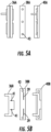
- Example embodiments of electrically conductive elements 24 are schematically shown in FIGS. 2A, 2B, and 2C , and are shown integrated with peripheral frames 10 in FIGS. 3A, 3B, and 3C .
- the example embodiments illustrated can be formed from electrically conductive film or foil; however, other configurations can be used such as wires or a metal mesh.
- Various types of metallized surfaces such as vapor-deposited, thermal spray-deposited, or other metallized layers can be used as an alternative or in addition to an electrically conductive film or foil.
- Electrically conductive elements can also be formed using printed circuit board fabrication techniques, for example, electrically conductive vias.
- the peripheral frame surface(s) adjacent to the electrically conductive elements can be an outward-facing surface or an inward-facing surface.
- outward-facing surface means any surface portion of the peripheral frame from which an imaginary line extending perpendicular to the peripheral frame surface would not intersect with the same peripheral frame.
- inward-facing surface means any surface portion of the peripheral frame from which an imaginary line extending perpendicular to the peripheral frame surface would intersect with the same peripheral frame. Examples of inward-facing peripheral frame surfaces include channels, notches, slots, or conductive vias formed by printed circuit board fabrication techniques.
- the electrically conductive element 24 can include a retention feature or alignment feature such as a film or foil with cut-outs 26 or 28, which can provide a technical effect of facilitating the alignment and folding of adjacent portions of the electrically conductive element around an edge or slot of the peripheral frame 10.
- FIGS. 3A and 3B show the electrically conductive elements 24 of FIGS. 2A and 2B disposed through the slots 18 of the peripheral frame 10, with a fold line at the position of the slot that is facilitated by the cut-outs 26 and 28 in the electrically conductive elements 24.
- FIGS. 4A, 4B, and 4C show example embodiments of integrated modules with peripheral frame 10, first and second electrically conductive elements 24 and 25 (with electrically conductive element 25 disposed on the opposite side of the frame as electrically conductive element 24), and electrocaloric element 34.
- the module includes one or more alignment features and/or retention features between the electrocaloric element 34 and the peripheral frame 10.
- alignment features include but are not limited to projections, holes, recesses, tabs, notches, crimping (of the electrocaloric element, or adhesive).
- the electrocaloric element 34 comprises an electrocaloric film with electrodes on opposite sides of the electrocaloric film.
- electrocaloric materials for the electrocaloric film can include but are not limited to inorganic (e.g., ceramics) or organic materials such as electrocaloric polymers, and polymer/ceramic composites. Composite materials such as organic polymers with inorganic fillers and/or fillers of a different organic polymer.
- electrocaloric film thickness can be in a range having a lower limit of 0.1 ⁇ m, more specifically 0.5 ⁇ m, and even more specifically 1 ⁇ m.
- the film thickness range can have an upper limit of 1000 ⁇ m, more specifically 100 ⁇ m, and even more specifically 10 ⁇ m. It is understood that these upper and lower range limits can be independently combined to disclose a number of different possible ranges.
- Examples of inorganic electrocaloric materials include but are not limited to PbTiO 3 ("PT"), Pb(Mg 1/3 Nb 2/3 )O 3 (“PMN”), PMN-PT, LiTaO 3 , barium strontium titanate (BST) or PZT (lead, zirconium, titanium, oxygen).
- Examples of electrocaloric polymers include, but are not limited to ferroelectric polymers, liquid crystal polymers, and liquid crystal elastomers. Ferroelectric polymers are crystalline polymers, or polymers with a high degree of crystallinity, where the crystalline alignment of polymer chains into lamellae and/or spherulite structures can be modified by application of an electric field.
- ferroelectric polymers include polyvinylidene fluoride (PVDF), polytriethylene fluoride, odd-numbered nylon, copolymers containing repeat units derived from vinylidene fluoride, and copolymers containing repeat units derived from triethylene fluoride.
- PVDF polyvinylidene fluoride
- Polyvinylidene fluoride and copolymers containing repeat units derived from vinylidene fluoride have been widely studied for their ferroelectric and electrocaloric properties.
- vinylidene fluoride-containing copolymers include copolymers with methyl methacrylate, and copolymers with one or more halogenated co-monomers including but not limited to trifluoroethylene, tetrafluoroethylene, chlorotrifluoroethylene, trichloroethylene, vinylidene chloride, vinyl chloride, and other halogenated unsaturated monomers.
- Liquid crystal polymers, or polymer liquid crystals comprise polymer molecules that include mesogenic groups.
- Mesogenic molecular structures are well-known, and are often described as rod-like or disk-like molecular structures having electron density orientations that produce a dipole moment in response to an external field such as an external electric field.
- Liquid crystal polymers typically comprise numerous mesogenic groups connected by non-mesogenic molecular structures.
- the non-mesogenic connecting structures and their connection, placement and spacing in the polymer molecule along with mesogenic structures are important in providing the fluid deformable response to the external field.
- the connecting structures provide stiffness low enough so that molecular realignment is induced by application of the external field, and high enough to provide the characteristics of a polymer when the external field is not applied.
- a liquid crystal polymer can have rod-like mesogenic structures in the polymer backbone separated by non-mesogenic spacer groups having flexibility to allow for reordering of the mesogenic groups in response to an external field. Such polymers are also known as main-chain liquid crystal polymers. In some exemplary embodiments, a liquid crystal polymer can have rod-like mesogenic structures attached as side groups attached to the polymer backbone. Such polymers are also known as side-chain liquid crystal polymers. Electrodes on the electrocaloric film can take different forms with various electrically conductive components. In some embodiments, the electrodes can be in the form of metalized layers or patterns on each side of the film such as disclosed in published PCT application WO 2017/111921 A1 .
- the heat transfer system includes a plurality of modules in a stack configuration.
- a stack of a plurality of modules will include a plurality of first and second electrically conductive elements 24/25 that are electrically connected to a plurality of first and second electrodes on a plurality of electrocaloric films disposed as electrocaloric elements 34 in a plurality of stacked peripheral frames 10.
- the first and second electrically conductive elements are also electrically connected in parallel on an electrical bus, also known as a bus bar, which are in turn connected to an electrical circuit or circuits (not shown) that can controllably energize the first and/or second electrode to subject the electrocaloric film to an electrical field.
- a bus bar can be formed from an electrically conductive element such as conductive film or metal foil or other metallized layer on a base or support, which itself be electrically or electrically conductive or non-conductive.
- Example embodiments of bus structures are schematically shown in FIGS. 5A and 5B , with electrically conductive film or metal foil 36A/B disposed on base or support 38A/B to form the bus structures 40A/B.
- the base or support 38B is shown with slots 39 in FIG. 5B for immobilizing or the electrically conductive film or metal foil 36A/B, which can have cut-outs 41 to facilitate folding the film or foil at the slot-line.
- the base or support 38A/B (and optionally the electrically conductive film or metal foil 36A/B) can also include one or more through-passages such as holes 43 to facilitate stacking of the electrical bus structures with a stack assembly support such as a stack assembly bolt (which can be the same as or different than any stack support structures for the stacked modules).
- the bus structures 40A/B can integrated with the stacked peripheral frames 10 (e.g., disposed between adjacent peripheral frames 10).
- the bus structures 40A/B can be stacked independently proximate to the outer perimeter 12 of stacked peripheral frames 10.
- the stacked modules are configured to provide flow paths for a working fluid between adjacent electrocaloric elements 34.
- the stack can include spacers between adjacent modules to provide space for such flow paths.
- the spacers can be disposed between adjacent peripheral frames 10. Multiple spacers can be stacked together, optionally with different profiles to create 3D structures. Alternatively, or in addition to discrete spacers, portions of the peripheral frame can formed with a thickness (i.e., in a direction parallel with stack height) along the periphery of the peripheral frame 10 to provide space between adjacent electrocaloric elements.
- spacers can be disposed in the area of opening 16 between adjacent electrocaloric elements 34, and can be integrated with the peripheral frame 10 such as shown for ribs 22 or can be discrete structures.
- structures disposed in the fluid flow space are configured to allow for fluid flow.
- such structures can be configured as strips disposed in a in a straight-line or non-straight-line longitudinal direction generally parallel to the direction of fluid flow, and/or can be formed from a fluid-permeable material such as a mesh or screen configuration.
- supports can be made from tensioned filament, strand, yarn, thread or other 1 dimensional materials that are wound around assembly bolts 58 ( FIG.
- spacer structures disposed in the fluid flow space between adjacent electrocaloric films can be made of a flexible material or structure to accommodate displacement of the electrocaloric films during energization/de-energization cycling.
- spacer structures disposed in the fluid flow space can be in the form of a mesh or other porous sheet parallel to the electrocaloric film, and can have a footprint in that plane that is smaller than, the same as, or larger than the footprint of the electrocaloric film.
- spacer structures between electrocaloric element electrodes at the same voltage can be electrically conductive spacer structures, which can be fabricated using printed circuit board fabrication techniques and can serve both as spacer and as electrically conductive elements.
- the spacer can be disposed as one or more mesh or screen spacers between adjacent electrocaloric films, which can in some embodiments be configured as a mat disposed in a plane parallel to the electrocaloric film.
- Example embodiments of discrete spacers 42A/B/C configured for stacking in between adjacent peripheral frames 10 are schematically shown in FIG. 6 .
- spacer 42A has holes 43A configured to align with the holes 20 of the peripheral frame 10 in FIGS. 1C and 1D
- spacer 42B has holes 43B configured to align with the holes 20 of the peripheral frame 10 in FIG. 1B
- spacer 42C has holes 43C configured to align with the holes 20 of the peripheral frame 10 in FIG. 1A .
- Example embodiments of stacked modules are schematically shown in FIGS. 7 and 8 .
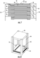
- the order of assembly can be varied and adapted to achieve target specifications, and the order shown in FIG. 7 is a typical example including peripheral frames 10, spacers 42 electrocaloric elements having electrocaloric films 46 with first electrodes 48 and second electrodes 50, first and second electrically conductive elements 24, 25 electrically connected the first and second electrodes 48, 50 and to first and second electrical buses 52, 54, respectively.
- FIG. 7 Example embodiments of stacked modules are schematically shown in FIGS. 7 and 8 .
- the order of assembly can be varied and adapted to achieve target specifications, and the order shown in FIG. 7 is a typical example including peripheral frames 10, spacers 42 electrocaloric elements having electrocaloric films 46 with first electrodes 48 and second electrodes 50, first and second electrically conductive elements 24, 25 electrically connected the first and second electrodes 48, 50 and to first and second electrical buses 52, 54, respectively.
- the electrocaloric films are disposed in the stack with a configuration such that the relative (top/bottom) orientation of the first and second electrodes 48, 50 is alternated with adjacent films so that each fluid flow path 44 has electrodes of matching polarity on each side of the fluid flow path 44, which can prevent arcing across the flow path gap.
- the elements of FIG. 7 are arranged in a repeating stack; however, elements 10, 44, 48, and 50 are only labeled for the top course of the stack for clarity of illustration.
- FIG. 8 shows a perspective view of a partially assembled stack in a support structure 56 with stack assembly bolts 58 through holes in the peripheral frames 10.
- a heat transfer system 310 comprises a stack 312 of modules with first and second electrical buses 314 and 316 in electrical communication with first and second electrodes on the electrocaloric films.
- the stack is in thermal communication with a heat sink 317 through a first thermal flow path 318, and in thermal communication with a heat source 320 through a second thermal flow path 322.
- the thermal flow paths are described below with respect thermal transfer through flow of working fluid through control devices 326 and 328 (e.g., flow dampers) between the stack and the heat sink and heat source.
- a controller 324 is configured to control electrical current to through a power source (not shown) to selectively activate the buses 314, 316.
- the module can be energized by energizing one bus bar/electrode while maintaining the other bus bar/electrode at a ground polarity.
- the controller 324 is also configured to open and close control devices 326 and 328 to selectively direct the working fluid along the first and second flow paths 318 and 322.
- the system 310 can be operated by the controller 324 applying an electric field as a voltage differential across the electrocaloric films in the stack to cause a decrease in entropy and a release of heat energy by the electrocaloric films.
- the controller 324 opens the control device 326 to transfer at least a portion of the released heat energy along flow path 318 to heat sink 317. This transfer of heat can occur after the temperature of the electrocaloric films has risen to a threshold temperature. In some embodiments, heat transfer to the heat sink 317 is begun as soon as the temperature of the electrocaloric films increases to be about equal to the temperature of the heat sink 317.
- the electric field can be removed. Removal of the electric field causes an increase in entropy and a decrease in heat energy of the electrocaloric films. This decrease in heat energy manifests as a reduction in temperature of the electrocaloric films to a temperature below that of the heat source 320.
- the controller 324 closes control device 326 to terminate flow along flow path 318, and opens control device 328 to transfer heat energy from the heat source 320 to the colder electrocaloric films in order to regenerate the electrocaloric films for another cycle.
- the electric field can be applied to the electrocaloric films to increase temperature until the temperature reaches a first threshold.
- the controller 324 opens control device 326 to transfer heat from the stack to the heat sink 317 until a second temperature threshold is reached.
- the electric field can continue to be applied during all or a portion of the time period between the first and second temperature thresholds, and is then removed to reduce the temperature until a third temperature threshold is reached.
- the controller 324 then closes control device 326 to terminate heat flow transfer along heat flow path 318, and opens control device 328 to transfer heat from the heat source 320 to the stack.
- the above steps can be optionally repeated until a target temperature of the conditioned space or thermal target (which can be either the heat source or the heat sink) is reached.
- any directions described herein are considered to be arbitrary and to not have any absolute meaning but only a meaning relative to other directions.
- the terms shall be relative to the view of the Figure shown on the page, i.e., “up” or “top” refers to the top of the page, “bottom” or “under” refers to the bottom of the page, “right” to the right-hand side of the page, and “left” to the left-hand side of the page.
Landscapes
- Engineering & Computer Science (AREA)
- Physics & Mathematics (AREA)
- Mechanical Engineering (AREA)
- Thermal Sciences (AREA)
- General Engineering & Computer Science (AREA)
- Cooling Or The Like Of Electrical Apparatus (AREA)
- Cooling Or The Like Of Semiconductors Or Solid State Devices (AREA)
- Resistance Heating (AREA)
Claims (15)
- Système de transfert de chaleur, comprenant :un module comprenantun cadre périphérique (10) ;un élément électrocalorique (34) disposé dans une ouverture du cadre périphérique, ledit élément électrocalorique comprenant un film électrocalorique (34), une première électrode (48) sur un premier côté du film électrocalorique, et une seconde électrode (50) sur un second côté du film électrocalorique ;un premier élément conducteur d'électricité (24) relié électriquement à la première électrode, ledit premier élément conducteur d'électricité étant disposé de manière adjacente à une première surface du cadre périphérique, ladite première surface se prolongeant depuis le film électrocalorique vers le périmètre du cadre périphérique ; etun second élément conducteur d'électricité (25) relié électriquement à la seconde électrode, ledit second élément conducteur d'électricité étant disposé de manière adjacente à une seconde surface du cadre périphérique, ladite seconde surface se prolongeant depuis le film électrocalorique vers le périmètre du cadre périphérique ;une première liaison à un circuit électrique, ladite première liaison étant disposée le long du périmètre de cadre périphérique à proximité de la première surface de cadre périphérique, et reliant électriquement le premier élément conducteur d'électricité au circuit électrique ;une seconde liaison à un circuit électrique, ladite seconde connexion étant disposée le long du périmètre de cadre périphérique à proximité de la seconde surface de cadre périphérique, et reliant électriquement le second élément conducteur d'électricité au circuit électrique ; etun chemin d'écoulement de fluide caloporteur comprenant une entrée, une sortie, et un chemin d'écoulement le long d'au moins une surface de l'élément électrocalorique ;dans lequel le module comprend en outre un support (22) se prolongeant de manière parallèle au film électrocalorique dans l'ouverture de cadre périphérique ; et caractérisé en ce que :
le support est perméable au fluide caloporteur. - Système de transfert de chaleur selon la revendication 1, comprenant en outre une caractéristique d'alignement entre le cadre périphérique (10) et l'élément électrocalorique (34).
- Système de transfert de chaleur selon la revendication 1 ou 2, comprenant en outre une caractéristique de rétention entre le cadre périphérique (10) et l'élément électrocalorique (34).
- Système de transfert de chaleur selon l'une quelconque des revendications précédentes, comprenant en outre une caractéristique d'alignement entre le cadre périphérique (10) et l'un des deux ou les deux premier et second éléments conducteurs d'électricité (24, 25).
- Système de transfert de chaleur selon l'une quelconque des revendications précédentes, comprenant en outre une caractéristique de rétention entre le cadre périphérique (10) et l'un des deux ou les deux premier et second éléments conducteurs d'électricité (24, 25).
- Système de transfert de chaleur selon l'une quelconque des revendications précédentes, dans lequel l'un des deux ou les deux premier et second éléments conducteurs d'électricité (24, 25) comprennent une couche conductrice d'électricité ou un fil le long des première et second surfaces respectives, ou
dans lequel l'un des deux ou les deux premier et second éléments conducteur d'électricité comportent une partie de connecteur électrique qui se prolonge à l'extérieur du périmètre de cadre périphérique (10). - Système de transfert de chaleur selon l'une quelconque des revendications précédentes, comprenant une pluralité desdits modules disposés en une pile.
- Système de transfert de chaleur selon la revendication 7, dans lequel la pluralité d'éléments électrocaloriques (34) sont reliés électriquement en parallèle, avec la pluralité de premières liaisons électriques reliées à un premier bus électrique le long d'une première partie de la pile à proximité de la pluralité de premières surfaces de cadre périphérique (10), et la pluralité de secondes liaisons électriques reliées à un second bus électrique le long d'une seconde partie de la pile à proximité de la pluralité de secondes surfaces de cadre périphérique.
- Système de transfert de chaleur selon la revendication 8, dans lequel l'un des deux ou les deux premier et second bus électriques comprennent un élément de bus conducteur d'électricité sur un support.
- Système de transfert de chaleur selon l'une quelconque des revendications 7 à 9, dans lequel le cadre périphérique (10) comporte une partie présentant une épaisseur conçue pour ménager un espace entre des éléments électrocaloriques (34) adjacents de la pile.
- Système de transfert de chaleur selon l'une quelconque des revendications 7 à 10, comprenant en outre une pluralité d'entretoises entre des cadres périphériques adjacents (10) ; et/ou
une pluralité d'entretoises entre des éléments électrocaloriques adjacents (34). - Système de transfert de chaleur selon l'une quelconque des revendications 8 à 11, dans lequel les supports de la pluralité de modules électrocaloriques séparent des films électrocaloriques (34) adjacents dans la pile.
- Système de transfert de chaleur selon l'une quelconque des revendications 8 à 12, comportant une ou plusieurs caractéristiques d'alignement entre des composants adjacents dans la pile ; et/ou
comportant une ou plusieurs caractéristiques de rétention de pile. - Système de transfert de chaleur selon l'une quelconque des revendications 8 à 13, dans lequel les éléments électrocaloriques (34) sont conçus de sorte que des chemins d'écoulement entre des éléments électrocaloriques adjacents sont disposés entre des premières électrodes (48) des éléments électrocaloriques adjacents ou entre des secondes électrodes (50) des éléments électrocaloriques adjacents.
- Procédé de réalisation du système de transfert de chaleur selon la revendication 8 ou l'une quelconque des revendications 9 à 13 telles qu'elles dépendent directement ou indirectement de la revendication 8, comprenant(a) la disposition d'un premier élément électrocalorique (34) dans l'ouverture d'un premier cadre périphérique (10), et la fixation de l'élément électrocalorique au premier cadre périphérique ;(b) la disposition d'un premier élément conducteur d'électricité adjacent à la première surface du premier cadre périphérique, et la liaison électrique du premier élément conducteur d'électricité à la première électrode (48) ;(c) la disposition d'un second élément conducteur d'électricité adjacent à la seconde surface du premier cadre périphérique, et la liaison électrique du second élément conducteur d'électricité à la seconde électrode (50) ;(d) l'empilement d'un second cadre périphérique sur le premier cadre périphérique et la répétition des étapes (a) à (d) pour constituer ladite pile ;(e) la liaison des premiers éléments conducteurs d'électricité au premier bus électrique ; et(f) la liaison des seconds éléments conducteurs d'électricité au second bus électrique.
Applications Claiming Priority (2)
| Application Number | Priority Date | Filing Date | Title |
|---|---|---|---|
| US201762592837P | 2017-11-30 | 2017-11-30 | |
| PCT/US2018/053499 WO2019108299A1 (fr) | 2017-11-30 | 2018-09-28 | Système de transfert de chaleur électrocalorique |
Publications (2)
| Publication Number | Publication Date |
|---|---|
| EP3717842A1 EP3717842A1 (fr) | 2020-10-07 |
| EP3717842B1 true EP3717842B1 (fr) | 2023-11-15 |
Family
ID=63858226
Family Applications (1)
| Application Number | Title | Priority Date | Filing Date |
|---|---|---|---|
| EP18786651.2A Active EP3717842B1 (fr) | 2017-11-30 | 2018-09-28 | Système de transfert de chaleur électrocalorique |
Country Status (4)
| Country | Link |
|---|---|
| US (1) | US11466906B2 (fr) |
| EP (1) | EP3717842B1 (fr) |
| CN (1) | CN111373215B (fr) |
| WO (1) | WO2019108299A1 (fr) |
Families Citing this family (3)
| Publication number | Priority date | Publication date | Assignee | Title |
|---|---|---|---|---|
| EP3394904B8 (fr) * | 2015-12-21 | 2021-04-14 | Raytheon Technologies Corporation | Procédé de formation des électrodes sur une couche electrocarique |
| WO2019108299A1 (fr) | 2017-11-30 | 2019-06-06 | Carrier Corporation | Système de transfert de chaleur électrocalorique |
| US11933524B2 (en) * | 2020-09-10 | 2024-03-19 | The Regents Of The University Of California | Tandem-structured cooling device driven by electrostatic force |
Family Cites Families (21)
| Publication number | Priority date | Publication date | Assignee | Title |
|---|---|---|---|---|
| US3638440A (en) * | 1970-11-20 | 1972-02-01 | Corning Glass Works | Closed-cycle electrocaloric refrigerator and method |
| US5644184A (en) | 1996-02-15 | 1997-07-01 | Thermodyne, Inc. | Piezo-pyroelectric energy converter and method |
| TW575158U (en) | 2003-03-20 | 2004-02-01 | Ind Tech Res Inst | Heat transfer structure for magnetic heat energy |
| EP2165074B1 (fr) * | 2007-06-08 | 2017-03-15 | Carver Scientific, Inc. | Dispositif et procédé de conversion d'énergie thermique en énergie électrique |
| FI121094B (fi) * | 2008-07-09 | 2010-06-30 | Jani Erkki Oksanen | Menetelmä ja laite lämmön siirtoon |
| US20100175392A1 (en) | 2009-01-15 | 2010-07-15 | Malloy Kevin J | Electrocaloric refrigerator and multilayer pyroelectric energy generator |
| US8869542B2 (en) | 2009-07-27 | 2014-10-28 | The Penn State Research Foundation | Polymer-based electrocaloric cooling devices |
| US9310109B2 (en) | 2011-09-21 | 2016-04-12 | Empire Technology Development Llc | Electrocaloric effect heat transfer device dimensional stress control |
| CN103827601B (zh) | 2011-09-21 | 2016-08-17 | 英派尔科技开发有限公司 | 异质电热效应热传递 |
| US20150033762A1 (en) | 2013-07-31 | 2015-02-05 | Nascent Devices Llc | Regenerative electrocaloric cooling device |
| WO2015014853A1 (fr) | 2013-08-01 | 2015-02-05 | Jožef Stefan Institute | Procédé pour conversion d'énergie électrocalorique |
| US9109818B2 (en) | 2013-09-20 | 2015-08-18 | Palo Alto Research Center Incorporated | Electrocaloric cooler and heat pump |
| JP2015094552A (ja) | 2013-11-13 | 2015-05-18 | 株式会社デンソー | 冷却装置 |
| WO2015156794A1 (fr) * | 2014-04-09 | 2015-10-15 | United Technologies Research Center | Régénérateur à contact direct à champ actif |
| GB2527025B (en) | 2014-04-14 | 2017-05-31 | Stelix Ltd | Refrigeration pill of longitudinally split construction |
| WO2017040625A1 (fr) | 2015-08-31 | 2017-03-09 | Sustainable Innovations, LLC | Composants de cellules électrochimiques modulaires, empilements, systèmes et procédé de fabrication |
| EP3394904B8 (fr) | 2015-12-21 | 2021-04-14 | Raytheon Technologies Corporation | Procédé de formation des électrodes sur une couche electrocarique |
| ES2912294T3 (es) | 2015-12-21 | 2022-05-25 | Carrier Corp | Sistema de transferencia de calor electrocalórico con líquido eléctricamente conductor |
| EP3394526B1 (fr) | 2015-12-21 | 2022-07-20 | Carrier Corporation | Pile modulaire de transfert de chaleur électrocalorique |
| CN113266959B (zh) | 2015-12-21 | 2023-04-28 | 联合工艺公司 | 电热热传递系统 |
| WO2019108299A1 (fr) | 2017-11-30 | 2019-06-06 | Carrier Corporation | Système de transfert de chaleur électrocalorique |
-
2018
- 2018-09-28 WO PCT/US2018/053499 patent/WO2019108299A1/fr not_active Ceased
- 2018-09-28 EP EP18786651.2A patent/EP3717842B1/fr active Active
- 2018-09-28 US US16/765,004 patent/US11466906B2/en active Active
- 2018-09-28 CN CN201880077545.9A patent/CN111373215B/zh active Active
Also Published As
| Publication number | Publication date |
|---|---|
| CN111373215B (zh) | 2023-02-21 |
| WO2019108299A1 (fr) | 2019-06-06 |
| US11466906B2 (en) | 2022-10-11 |
| US20200309421A1 (en) | 2020-10-01 |
| EP3717842A1 (fr) | 2020-10-07 |
| CN111373215A (zh) | 2020-07-03 |
Similar Documents
| Publication | Publication Date | Title |
|---|---|---|
| US20210381726A1 (en) | Electrocaloric heat transfer system | |
| EP3394526B1 (fr) | Pile modulaire de transfert de chaleur électrocalorique | |
| EP3717842B1 (fr) | Système de transfert de chaleur électrocalorique | |
| EP3638964B1 (fr) | Module électrocalorique et système de transfert de chaleur électrocalorique avec des électrodes à motifs, et en conséquence un procédé de transfert de chaleur | |
| EP3638965B1 (fr) | Module électrocalorique avec électronique intégrée, méthode de fabrication du module électrocalorique et méthode de transfert de chaleur par l'utilisation du module électrocalorique | |
| US11859878B2 (en) | Electrocaloric heat transfer system | |
| EP3841620B1 (fr) | Système de transfert de chaleur electrocalorique | |
| US20210308733A1 (en) | Method of assembling an electrocaloric article and electrocaloric heat transfer system | |
| US20210199352A1 (en) | Electrocaloric heat transfer articles and systems | |
| US12135150B2 (en) | Electrocaloric heat transfer articles and systems |
Legal Events
| Date | Code | Title | Description |
|---|---|---|---|
| STAA | Information on the status of an ep patent application or granted ep patent |
Free format text: STATUS: UNKNOWN |
|
| STAA | Information on the status of an ep patent application or granted ep patent |
Free format text: STATUS: THE INTERNATIONAL PUBLICATION HAS BEEN MADE |
|
| PUAI | Public reference made under article 153(3) epc to a published international application that has entered the european phase |
Free format text: ORIGINAL CODE: 0009012 |
|
| STAA | Information on the status of an ep patent application or granted ep patent |
Free format text: STATUS: REQUEST FOR EXAMINATION WAS MADE |
|
| 17P | Request for examination filed |
Effective date: 20200601 |
|
| AK | Designated contracting states |
Kind code of ref document: A1 Designated state(s): AL AT BE BG CH CY CZ DE DK EE ES FI FR GB GR HR HU IE IS IT LI LT LU LV MC MK MT NL NO PL PT RO RS SE SI SK SM TR |
|
| AX | Request for extension of the european patent |
Extension state: BA ME |
|
| DAV | Request for validation of the european patent (deleted) | ||
| DAX | Request for extension of the european patent (deleted) | ||
| STAA | Information on the status of an ep patent application or granted ep patent |
Free format text: STATUS: EXAMINATION IS IN PROGRESS |
|
| 17Q | First examination report despatched |
Effective date: 20211216 |
|
| GRAP | Despatch of communication of intention to grant a patent |
Free format text: ORIGINAL CODE: EPIDOSNIGR1 |
|
| STAA | Information on the status of an ep patent application or granted ep patent |
Free format text: STATUS: GRANT OF PATENT IS INTENDED |
|
| INTG | Intention to grant announced |
Effective date: 20230531 |
|
| P01 | Opt-out of the competence of the unified patent court (upc) registered |
Effective date: 20230527 |
|
| GRAS | Grant fee paid |
Free format text: ORIGINAL CODE: EPIDOSNIGR3 |
|
| GRAA | (expected) grant |
Free format text: ORIGINAL CODE: 0009210 |
|
| STAA | Information on the status of an ep patent application or granted ep patent |
Free format text: STATUS: THE PATENT HAS BEEN GRANTED |
|
| AK | Designated contracting states |
Kind code of ref document: B1 Designated state(s): AL AT BE BG CH CY CZ DE DK EE ES FI FR GB GR HR HU IE IS IT LI LT LU LV MC MK MT NL NO PL PT RO RS SE SI SK SM TR |
|
| REG | Reference to a national code |
Ref country code: CH Ref legal event code: EP Ref country code: GB Ref legal event code: FG4D |
|
| REG | Reference to a national code |
Ref country code: DE Ref legal event code: R096 Ref document number: 602018061158 Country of ref document: DE |
|
| REG | Reference to a national code |
Ref country code: IE Ref legal event code: FG4D |
|
| REG | Reference to a national code |
Ref country code: LT Ref legal event code: MG9D |
|
| REG | Reference to a national code |
Ref country code: NL Ref legal event code: MP Effective date: 20231115 |
|
| PG25 | Lapsed in a contracting state [announced via postgrant information from national office to epo] |
Ref country code: GR Free format text: LAPSE BECAUSE OF FAILURE TO SUBMIT A TRANSLATION OF THE DESCRIPTION OR TO PAY THE FEE WITHIN THE PRESCRIBED TIME-LIMIT Effective date: 20240216 |
|
| PG25 | Lapsed in a contracting state [announced via postgrant information from national office to epo] |
Ref country code: IS Free format text: LAPSE BECAUSE OF FAILURE TO SUBMIT A TRANSLATION OF THE DESCRIPTION OR TO PAY THE FEE WITHIN THE PRESCRIBED TIME-LIMIT Effective date: 20240315 |
|
| PG25 | Lapsed in a contracting state [announced via postgrant information from national office to epo] |
Ref country code: LT Free format text: LAPSE BECAUSE OF FAILURE TO SUBMIT A TRANSLATION OF THE DESCRIPTION OR TO PAY THE FEE WITHIN THE PRESCRIBED TIME-LIMIT Effective date: 20231115 |
|
| REG | Reference to a national code |
Ref country code: AT Ref legal event code: MK05 Ref document number: 1632109 Country of ref document: AT Kind code of ref document: T Effective date: 20231115 |
|
| PG25 | Lapsed in a contracting state [announced via postgrant information from national office to epo] |
Ref country code: NL Free format text: LAPSE BECAUSE OF FAILURE TO SUBMIT A TRANSLATION OF THE DESCRIPTION OR TO PAY THE FEE WITHIN THE PRESCRIBED TIME-LIMIT Effective date: 20231115 |
|
| PG25 | Lapsed in a contracting state [announced via postgrant information from national office to epo] |
Ref country code: AT Free format text: LAPSE BECAUSE OF FAILURE TO SUBMIT A TRANSLATION OF THE DESCRIPTION OR TO PAY THE FEE WITHIN THE PRESCRIBED TIME-LIMIT Effective date: 20231115 |
|
| PG25 | Lapsed in a contracting state [announced via postgrant information from national office to epo] |
Ref country code: ES Free format text: LAPSE BECAUSE OF FAILURE TO SUBMIT A TRANSLATION OF THE DESCRIPTION OR TO PAY THE FEE WITHIN THE PRESCRIBED TIME-LIMIT Effective date: 20231115 |
|
| PG25 | Lapsed in a contracting state [announced via postgrant information from national office to epo] |
Ref country code: NL Free format text: LAPSE BECAUSE OF FAILURE TO SUBMIT A TRANSLATION OF THE DESCRIPTION OR TO PAY THE FEE WITHIN THE PRESCRIBED TIME-LIMIT Effective date: 20231115 Ref country code: LT Free format text: LAPSE BECAUSE OF FAILURE TO SUBMIT A TRANSLATION OF THE DESCRIPTION OR TO PAY THE FEE WITHIN THE PRESCRIBED TIME-LIMIT Effective date: 20231115 Ref country code: IS Free format text: LAPSE BECAUSE OF FAILURE TO SUBMIT A TRANSLATION OF THE DESCRIPTION OR TO PAY THE FEE WITHIN THE PRESCRIBED TIME-LIMIT Effective date: 20240315 Ref country code: GR Free format text: LAPSE BECAUSE OF FAILURE TO SUBMIT A TRANSLATION OF THE DESCRIPTION OR TO PAY THE FEE WITHIN THE PRESCRIBED TIME-LIMIT Effective date: 20240216 Ref country code: ES Free format text: LAPSE BECAUSE OF FAILURE TO SUBMIT A TRANSLATION OF THE DESCRIPTION OR TO PAY THE FEE WITHIN THE PRESCRIBED TIME-LIMIT Effective date: 20231115 Ref country code: BG Free format text: LAPSE BECAUSE OF FAILURE TO SUBMIT A TRANSLATION OF THE DESCRIPTION OR TO PAY THE FEE WITHIN THE PRESCRIBED TIME-LIMIT Effective date: 20240215 Ref country code: AT Free format text: LAPSE BECAUSE OF FAILURE TO SUBMIT A TRANSLATION OF THE DESCRIPTION OR TO PAY THE FEE WITHIN THE PRESCRIBED TIME-LIMIT Effective date: 20231115 Ref country code: PT Free format text: LAPSE BECAUSE OF FAILURE TO SUBMIT A TRANSLATION OF THE DESCRIPTION OR TO PAY THE FEE WITHIN THE PRESCRIBED TIME-LIMIT Effective date: 20240315 |
|
| PG25 | Lapsed in a contracting state [announced via postgrant information from national office to epo] |
Ref country code: SE Free format text: LAPSE BECAUSE OF FAILURE TO SUBMIT A TRANSLATION OF THE DESCRIPTION OR TO PAY THE FEE WITHIN THE PRESCRIBED TIME-LIMIT Effective date: 20231115 Ref country code: RS Free format text: LAPSE BECAUSE OF FAILURE TO SUBMIT A TRANSLATION OF THE DESCRIPTION OR TO PAY THE FEE WITHIN THE PRESCRIBED TIME-LIMIT Effective date: 20231115 Ref country code: PL Free format text: LAPSE BECAUSE OF FAILURE TO SUBMIT A TRANSLATION OF THE DESCRIPTION OR TO PAY THE FEE WITHIN THE PRESCRIBED TIME-LIMIT Effective date: 20231115 Ref country code: NO Free format text: LAPSE BECAUSE OF FAILURE TO SUBMIT A TRANSLATION OF THE DESCRIPTION OR TO PAY THE FEE WITHIN THE PRESCRIBED TIME-LIMIT Effective date: 20240215 Ref country code: LV Free format text: LAPSE BECAUSE OF FAILURE TO SUBMIT A TRANSLATION OF THE DESCRIPTION OR TO PAY THE FEE WITHIN THE PRESCRIBED TIME-LIMIT Effective date: 20231115 Ref country code: HR Free format text: LAPSE BECAUSE OF FAILURE TO SUBMIT A TRANSLATION OF THE DESCRIPTION OR TO PAY THE FEE WITHIN THE PRESCRIBED TIME-LIMIT Effective date: 20231115 |
|
| RAP4 | Party data changed (patent owner data changed or rights of a patent transferred) |
Owner name: CARRIER CORPORATION |
|
| PG25 | Lapsed in a contracting state [announced via postgrant information from national office to epo] |
Ref country code: DK Free format text: LAPSE BECAUSE OF FAILURE TO SUBMIT A TRANSLATION OF THE DESCRIPTION OR TO PAY THE FEE WITHIN THE PRESCRIBED TIME-LIMIT Effective date: 20231115 |
|
| PG25 | Lapsed in a contracting state [announced via postgrant information from national office to epo] |
Ref country code: CZ Free format text: LAPSE BECAUSE OF FAILURE TO SUBMIT A TRANSLATION OF THE DESCRIPTION OR TO PAY THE FEE WITHIN THE PRESCRIBED TIME-LIMIT Effective date: 20231115 |
|
| PG25 | Lapsed in a contracting state [announced via postgrant information from national office to epo] |
Ref country code: SK Free format text: LAPSE BECAUSE OF FAILURE TO SUBMIT A TRANSLATION OF THE DESCRIPTION OR TO PAY THE FEE WITHIN THE PRESCRIBED TIME-LIMIT Effective date: 20231115 |
|
| PG25 | Lapsed in a contracting state [announced via postgrant information from national office to epo] |
Ref country code: SM Free format text: LAPSE BECAUSE OF FAILURE TO SUBMIT A TRANSLATION OF THE DESCRIPTION OR TO PAY THE FEE WITHIN THE PRESCRIBED TIME-LIMIT Effective date: 20231115 Ref country code: SK Free format text: LAPSE BECAUSE OF FAILURE TO SUBMIT A TRANSLATION OF THE DESCRIPTION OR TO PAY THE FEE WITHIN THE PRESCRIBED TIME-LIMIT Effective date: 20231115 Ref country code: RO Free format text: LAPSE BECAUSE OF FAILURE TO SUBMIT A TRANSLATION OF THE DESCRIPTION OR TO PAY THE FEE WITHIN THE PRESCRIBED TIME-LIMIT Effective date: 20231115 Ref country code: IT Free format text: LAPSE BECAUSE OF FAILURE TO SUBMIT A TRANSLATION OF THE DESCRIPTION OR TO PAY THE FEE WITHIN THE PRESCRIBED TIME-LIMIT Effective date: 20231115 Ref country code: EE Free format text: LAPSE BECAUSE OF FAILURE TO SUBMIT A TRANSLATION OF THE DESCRIPTION OR TO PAY THE FEE WITHIN THE PRESCRIBED TIME-LIMIT Effective date: 20231115 Ref country code: DK Free format text: LAPSE BECAUSE OF FAILURE TO SUBMIT A TRANSLATION OF THE DESCRIPTION OR TO PAY THE FEE WITHIN THE PRESCRIBED TIME-LIMIT Effective date: 20231115 Ref country code: CZ Free format text: LAPSE BECAUSE OF FAILURE TO SUBMIT A TRANSLATION OF THE DESCRIPTION OR TO PAY THE FEE WITHIN THE PRESCRIBED TIME-LIMIT Effective date: 20231115 |
|
| REG | Reference to a national code |
Ref country code: DE Ref legal event code: R097 Ref document number: 602018061158 Country of ref document: DE |
|
| PLBE | No opposition filed within time limit |
Free format text: ORIGINAL CODE: 0009261 |
|
| STAA | Information on the status of an ep patent application or granted ep patent |
Free format text: STATUS: NO OPPOSITION FILED WITHIN TIME LIMIT |
|
| 26N | No opposition filed |
Effective date: 20240819 |
|
| PG25 | Lapsed in a contracting state [announced via postgrant information from national office to epo] |
Ref country code: SI Free format text: LAPSE BECAUSE OF FAILURE TO SUBMIT A TRANSLATION OF THE DESCRIPTION OR TO PAY THE FEE WITHIN THE PRESCRIBED TIME-LIMIT Effective date: 20231115 |
|
| PG25 | Lapsed in a contracting state [announced via postgrant information from national office to epo] |
Ref country code: SI Free format text: LAPSE BECAUSE OF FAILURE TO SUBMIT A TRANSLATION OF THE DESCRIPTION OR TO PAY THE FEE WITHIN THE PRESCRIBED TIME-LIMIT Effective date: 20231115 |
|
| PG25 | Lapsed in a contracting state [announced via postgrant information from national office to epo] |
Ref country code: MC Free format text: LAPSE BECAUSE OF FAILURE TO SUBMIT A TRANSLATION OF THE DESCRIPTION OR TO PAY THE FEE WITHIN THE PRESCRIBED TIME-LIMIT Effective date: 20231115 |
|
| REG | Reference to a national code |
Ref country code: CH Ref legal event code: PL |
|
| PG25 | Lapsed in a contracting state [announced via postgrant information from national office to epo] |
Ref country code: LU Free format text: LAPSE BECAUSE OF NON-PAYMENT OF DUE FEES Effective date: 20240928 |
|
| REG | Reference to a national code |
Ref country code: BE Ref legal event code: MM Effective date: 20240930 |
|
| PG25 | Lapsed in a contracting state [announced via postgrant information from national office to epo] |
Ref country code: BE Free format text: LAPSE BECAUSE OF NON-PAYMENT OF DUE FEES Effective date: 20240930 |
|
| PG25 | Lapsed in a contracting state [announced via postgrant information from national office to epo] |
Ref country code: CH Free format text: LAPSE BECAUSE OF NON-PAYMENT OF DUE FEES Effective date: 20240930 |
|
| PG25 | Lapsed in a contracting state [announced via postgrant information from national office to epo] |
Ref country code: IE Free format text: LAPSE BECAUSE OF NON-PAYMENT OF DUE FEES Effective date: 20240928 |
|
| PG25 | Lapsed in a contracting state [announced via postgrant information from national office to epo] |
Ref country code: FI Free format text: LAPSE BECAUSE OF FAILURE TO SUBMIT A TRANSLATION OF THE DESCRIPTION OR TO PAY THE FEE WITHIN THE PRESCRIBED TIME-LIMIT Effective date: 20231115 |
|
| PGFP | Annual fee paid to national office [announced via postgrant information from national office to epo] |
Ref country code: DE Payment date: 20250820 Year of fee payment: 8 |
|
| PGFP | Annual fee paid to national office [announced via postgrant information from national office to epo] |
Ref country code: GB Payment date: 20250820 Year of fee payment: 8 |
|
| PGFP | Annual fee paid to national office [announced via postgrant information from national office to epo] |
Ref country code: FR Payment date: 20250820 Year of fee payment: 8 |
|
| PG25 | Lapsed in a contracting state [announced via postgrant information from national office to epo] |
Ref country code: CY Free format text: LAPSE BECAUSE OF FAILURE TO SUBMIT A TRANSLATION OF THE DESCRIPTION OR TO PAY THE FEE WITHIN THE PRESCRIBED TIME-LIMIT; INVALID AB INITIO Effective date: 20180928 |
|
| PG25 | Lapsed in a contracting state [announced via postgrant information from national office to epo] |
Ref country code: HU Free format text: LAPSE BECAUSE OF FAILURE TO SUBMIT A TRANSLATION OF THE DESCRIPTION OR TO PAY THE FEE WITHIN THE PRESCRIBED TIME-LIMIT; INVALID AB INITIO Effective date: 20180928 |