EP3717873B1 - Débitmètre - Google Patents
Débitmètre Download PDFInfo
- Publication number
- EP3717873B1 EP3717873B1 EP18836584.5A EP18836584A EP3717873B1 EP 3717873 B1 EP3717873 B1 EP 3717873B1 EP 18836584 A EP18836584 A EP 18836584A EP 3717873 B1 EP3717873 B1 EP 3717873B1
- Authority
- EP
- European Patent Office
- Prior art keywords
- flowmeter
- flow
- fluid
- intermediate portion
- passageway
- Prior art date
- Legal status (The legal status is an assumption and is not a legal conclusion. Google has not performed a legal analysis and makes no representation as to the accuracy of the status listed.)
- Active
Links
Images


Classifications
-
- G—PHYSICS
- G01—MEASURING; TESTING
- G01F—MEASURING VOLUME, VOLUME FLOW, MASS FLOW OR LIQUID LEVEL; METERING BY VOLUME
- G01F1/00—Measuring the volume flow or mass flow of fluid or fluent solid material wherein the fluid passes through a meter in a continuous flow
- G01F1/66—Measuring the volume flow or mass flow of fluid or fluent solid material wherein the fluid passes through a meter in a continuous flow by measuring frequency, phase shift or propagation time of electromagnetic or other waves, e.g. using ultrasonic flowmeters
- G01F1/662—Constructional details
-
- G—PHYSICS
- G01—MEASURING; TESTING
- G01F—MEASURING VOLUME, VOLUME FLOW, MASS FLOW OR LIQUID LEVEL; METERING BY VOLUME
- G01F1/00—Measuring the volume flow or mass flow of fluid or fluent solid material wherein the fluid passes through a meter in a continuous flow
- G01F1/66—Measuring the volume flow or mass flow of fluid or fluent solid material wherein the fluid passes through a meter in a continuous flow by measuring frequency, phase shift or propagation time of electromagnetic or other waves, e.g. using ultrasonic flowmeters
- G01F1/667—Arrangements of transducers for ultrasonic flowmeters; Circuits for operating ultrasonic flowmeters
-
- G—PHYSICS
- G01—MEASURING; TESTING
- G01N—INVESTIGATING OR ANALYSING MATERIALS BY DETERMINING THEIR CHEMICAL OR PHYSICAL PROPERTIES
- G01N29/00—Investigating or analysing materials by the use of ultrasonic, sonic or infrasonic waves; Visualisation of the interior of objects by transmitting ultrasonic or sonic waves through the object
- G01N29/02—Analysing fluids
-
- G—PHYSICS
- G01—MEASURING; TESTING
- G01N—INVESTIGATING OR ANALYSING MATERIALS BY DETERMINING THEIR CHEMICAL OR PHYSICAL PROPERTIES
- G01N29/00—Investigating or analysing materials by the use of ultrasonic, sonic or infrasonic waves; Visualisation of the interior of objects by transmitting ultrasonic or sonic waves through the object
- G01N29/22—Details, e.g. general constructional or apparatus details
- G01N29/222—Constructional or flow details for analysing fluids
-
- G—PHYSICS
- G01—MEASURING; TESTING
- G01F—MEASURING VOLUME, VOLUME FLOW, MASS FLOW OR LIQUID LEVEL; METERING BY VOLUME
- G01F15/00—Details of, or accessories for, apparatus of groups G01F1/00 - G01F13/00 insofar as such details or appliances are not adapted to particular types of such apparatus
- G01F15/18—Supports or connecting means for meters
- G01F15/185—Connecting means, e.g. bypass conduits
Definitions
- This invention relates to a flowmeter.
- this invention relates to a flowmeter for measuring fluid flow through a pipe and/or passageway.
- US 2011/0088483 A1 discloses a flowmeter having sensors which are mounted within inlet and outlet passages and an intermediate passage which has a reduced cross-sectional area compared to the inlet and outlet passages. Further, the intermediate passage is angled relative the inlet and outlet passages. However, the intermediate passage is angled away from a line of sight extending between the sensors. Angling the intermediate passage in this manner increases an angle between the fluid flow direction and the line of sight between the sensors which reduces measurement accuracy.
- US 2011/271770 A1 (Wiest Achim et al) 2008 discloses a flowmeter having an intermediate passage which is angled relative inlet and outlet passages and sensors which are mounted diametrically opposite each other and which protrude into the flow passage.
- the angle between an axis of the central passage and axes of the inlet and outlet passages is cited as no less than 30 degrees. This relatively high angle increases turbulence which reduces measurement accuracy.
- the inlet and outlet passages are not co-axial which reduces ease of installation and/or retro-fitting and increases bulk of the flow meter.
- a curved flow channel and additional sensors are provided. The particular design utilises additional sensors, flow channels both curved and angled more than 30 degrees which results in increased power consumption and increased bulk of the flow meter.
- WO 2013/157990 A1 discloses a flowmeter having sensors which extend into a fluid flow channel and are arranged on either side of a tubular insert. Similarly to US 5,553,505 A , the sensors are not arranged diametrically opposite each other, which reduces measurement accuracy.
- FR 3 047 068 A1 discloses a flowmeter having sensors which are arranged outside of a flow channel. Sensors mounted outside of the flow channel increases general bulk of the flowmeter. Once again, there is a relatively large angle between the fluid flow direction in the intermediate portion and a line of sight between the sensors, which reduces measurement accuracy.
- a flowmeter according to claim 1 including:
- the body defines inlet and outlet portions for allowing fluid to flow into and out of the passageway and an intermediate portion between the inlet and outlet portions having a reduced cross-sectional area compared to the inlet and outlet portions.
- a central axis of the intermediate portion is offset relative central axes of the inlet and outlet portions. More particularly, the central axis of the intermediate portion may be offset an angle in the range of 2 degrees and 6 degrees, preferably being 3.8 degrees, relative the central axes of the inlet and outlet portions.
- the passageway may taper generally from the outlet and inlet portions towards the intermediate portion to encourage laminar flow therethrough.
- Guide formations may be provided which extend into the passageway for guiding the flow of fluid therethrough and encouraging laminar flow of the fluid.
- the guide formations may be sized, shaped and/or configured to guide the flow of fluid along a generally wave-like, undulating and/or arcuate path through the intermediate portion during an operative fluid flow condition wherein fluid is flowing through the passageway.
- the guide formations may be located diametrically opposite each other.
- the guide formations may be shaped to form reduced flow zones in the vicinity thereof during the operative fluid flow condition, the reduced flow zones preferably being formed towards the end regions of the intermediate zone between the guide formations. It is to be appreciated that the reduced flow zone may improve accuracy of the sensing arrangement by reducing turbulent flow, noise, cavitation and the formation of eddy currents around the guide formations in use.
- the guide formations may define sensor housings for housing sensors of the sensing arrangement.
- the sensor housings may comprise a mounting member for mounting a sensor of the sensing arrangement thereon and a closure member for closing an inside region or cavity defined by the guide formation.
- the mounting members of each guide formation may be orientated relative the passageway such that sensors mounted thereon face each other along the central axis of the intermediate portion of the passageway.
- the closure member may be configured to close and/or seal the inside region or cavity defined by the housing and inhibit the ingress of fluid into the inside region during the operative fluid flow condition.
- the body may comprise a pair of hollow members which define passages which taper from one end region towards an opposing end region thereof.
- the pair of hollow members may be connected via opposing end regions thereof during an operative aligned condition.
- the pair of hollow members may be substantially identical in shape and/or size.
- a sealing member preferably in the form of an O-ring, may be provided for sealing a fit between the hollow members during an operative aligned condition.
- An aperture may be defined in a wall of each hollow member which extends into the inside region of the sensor housing for allowing wiring to be connected to the sensors in order to provide power thereto.
- Sensors of the sensing arrangement may be in the form of a transmitter and a receiver which may be housed within the sensor housings of the guide formations, preferably being mounted on the mounting members thereof.
- the transmitter and receiver may be in the form of a pair of transceivers.
- the transceivers may be arranged in electrical communication with a processor which may be configured to process signals passing between the transceivers during the operative fluid flow condition.
- the processor may be configured to calculate a mass and/or volume flow rate of fluid flowing through the passageway, typically being based on a time of flight measurement of the signals passing between the transceivers.
- the transceivers may be configured to send signals between each other every 1 to 4 seconds, preferably being every 2 seconds, further preferably the transceivers may be configured to send signals between each other at a frequency in the range of 0.25Hz to 100Hz.
- the transceivers may be in the form of piezoelectric transceivers.
- the piezoelectric transceivers may be configured to vibrate when subject to a potential difference and/or voltage.
- the piezoelectric transceivers may be configured to vibrate at any suitable frequency, preferably vibrating at a frequency so as to produce ultrasonic sound waves in the range of 20kHz and 10MHz, preferably being 1MHz.
- Connecting members may extend from the body, preferably extending away from the body in the region of the inlet and outlet portions, for allowing the body to be connected in-line with a water supply.
- a housing may be provided for housing the body, processor and a power source in use.
- the housing may include a first portion for housing the body and a second portion for housing the power source and the processor.
- the housing may have a generally rectangular form, preferably resembling a generally rectangular prism.
- the housing may include a pair of openings defined towards opposing longitudinal end regions thereof, the openings preferably leading to the first portion of the housing, for receiving corresponding hollow members complementally therein.
- a locating formation may be provided for locating and guiding the hollow members into the operative aligned condition while being received by the first portion of the housing.
- the locating formation may be in the form of a slot and key arrangement, slots preferably being defined on inner walls of the housing and key-like protrusions being defined on an outer surface of the hollow members.
- Retaining members may be provided for retaining the hollow members within the housing, particularly in the operative aligned condition.
- the retaining members may be sized, shaped and/or configured to be interposed between an outer surface of the hollow member and a wall of an opening of the housing.
- the retaining members may have a generally ring shape and may be dimensioned so as to form a friction fit between the hollow member and the wall of the opening. It is to be appreciated that the retaining member may be friction welded into position between the hollow member and the wall of the opening.
- the body and housing may be manufactured form any suitable synthetic plastics material, preferably being manufactured from a thermoplastic of the group including acrylic, polypropylene, polystyrene, polyethylene, polyphenylene, polyaryletherketone and polyvinylchloride, preferably being polyphenylene sulphide having product code Ryton R-7-120BL which may be manufactured by Solvay TM .
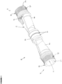
- reference numeral 10 refers generally to a flowmeter in accordance with the present invention.
- the flowmeter 10 includes a body 12 defining a passageway 14 for allowing fluid to flow therethrough and a sensing arrangement 16 which extends substantially inwardly from opposing end regions 18 of the passageway 14 for sensing a flow of fluid through the passageway 14 along an axis 20 which is substantially parallel thereto.
- the body 12 defines inlet and outlet portions 22 and 24 for allowing fluid to flow into and out of the passageway 14 and an intermediate portion 26 between the inlet and outlet portions 22 and 24 having a reduced cross-sectional area compared to the inlet and outlet portions 22 and 24.
- a central axis 28 of the intermediate portion 26 is offset relative central axes 30 of the inlet and outlet portions 22 and 24. More particularly, the central axis 28 of the intermediate portion 26 is offset an angle in the range of 2 degrees and 6 degrees, typically being 3.8 degrees, relative the central axes 30 of the inlet and outlet portions 22 and 24.
- the passageway 14 tapers generally from the outlet and inlet portions 22 and 24 towards the intermediate portion 26 to encourage laminar flow therethrough.
- Guide formations 32 are provided which extend into the passageway 14 for guiding the flow of fluid therethrough and encouraging laminar flow of the fluid.
- the guide formations 32 are sized, shaped and configured to guide the flow of fluid along a generally wave-like path through the intermediate portion 26 during an operative fluid flow condition wherein fluid is flowing through the passageway 14.
- the guide formations 32 are located diametrically opposite each other. Further, the guide formations 32 are shaped to form reduced flow zones 34 in the vicinity thereof during the operative fluid flow condition, the reduced flow zones 34 typically being formed towards the end regions 18 of the intermediate zone 26 between the guide formations 32. It is to be appreciated that the reduced flow zone 34 improves accuracy of the sensing arrangement 16 by reducing turbulent flow, noise, cavitation and the formation of eddy currents around the guide formations 32 in use.
- the guide formations 32 define sensor housings 36 for housing sensors in the form of transceivers 38 of the sensing arrangement 16.
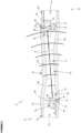
- the sensor housings 36 may comprise a mounting member 40 for mounting a transceiver 38 thereon and a closure member 42 for closing an inside region 44 defined by the guide formation 32.
- the mounting members 40 of each guide formation 32 are orientated relative the passageway 14 such that transceivers 38 mounted thereon face each other along the intermediate portion 26 of the passageway 14.
- the closure member 42 is configured to close and seal the inside region 44 defined by the housing 36 and inhibit the ingress of fluid into the inside region 44 during the operative fluid flow condition.
- the body 12 comprises a pair of hollow members 46 which define passages 48 which taper from one end region 50 towards an opposing end region 52 thereof.
- the pair of hollow members 46 are connected via opposing end regions 52 thereof during an operative aligned condition.
- the pair of hollow members 46 are substantially identical in shape and size.
- a sealing member in the form of an O-ring 54 is provided for sealing a fit between the hollow members 46 during an operative aligned condition.
- An aperture 56 is defined in a wall 58 of each hollow member 46 which extends into the inside region 44 of the sensor housing 36 for allowing wiring 60 to be connected to the transceivers 38 in order to provide power thereto.
- the transceivers 38 are arranged in electrical communication with a processor (not shown) which is configured to process signals passing between the transceivers 38 during the operative fluid flow condition, the processor (not shown) is configured to calculate a mass or volume flow rate of fluid flowing through the passageway 14, typically being based on a time of flight measurement of the signals passing between the transceivers 38.
- the transceivers 38 are configured to send signals between each other every 1 to 4 seconds, typically being every 2 seconds.
- the transceivers 38 can be configured to send signals between each other at a frequency in the range of 0.25Hz to 100Hz.
- the transceivers 38 are in the form of piezoelectric transceivers.
- the piezoelectric transceivers 38 are configured to vibrate when subject to a potential difference.
- the piezoelectric transceivers 38 are configured to vibrate at any suitable frequency, preferably vibrating at a frequency so as to produce ultrasonic sound waves in the range of 20kHz and 10MHz, typically being 1MHz.
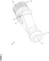
- Connecting members 62 having threaded outer profiles extend from the body 12, typically extending away from the body 12 in the region of the inlet and outlet portions 22 and 24, for allowing the body 12 to be connected in-line with a water supply.
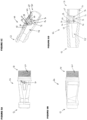
- a housing 66 is provided for housing the body 12, processor (not shown) and a power source (not shown) in use.
- the housing 66 includes a first portion 68 for housing the body 12 and a second portion 70 for housing the power source (not shown) for the transceivers 38 and the processor (not shown).
- the housing 66 has a generally rectangular form, typically resembling a generally rectangular prism.
- the housing 66 includes a pair of openings 72 defined towards opposing end regions 74 thereof, the openings 72 typically leading to the first portion 68 of the housing 66 for receiving corresponding hollow members 46 complementally therein.
- a locating formation in the form of a slot and key arrangement 76 is provided for locating and guiding the hollow members 46 into the operative aligned condition while being received by the first portion 68 of the housing 66.
- Slots 76.1 are typically defined on inner walls 78 of the housing 66 and key-like protrusions 76.2 are defined on an outer surface 80 of the hollow members 46.
- Retaining members 82 are provided for retaining the hollow members 46 within the housing 66, particularly in the operative aligned condition.
- the retaining members 82 are sized, shaped and configured to be interposed between the outer surface 80 of the hollow member 46 and a wall of an opening 72 of the housing 66.
- the retaining members 82 have a generally ring shape and are dimensioned to form a friction fit between the hollow member 46 and the wall 84 of the opening 72. It is to be appreciated that the retaining member 82 is friction welded into position between the hollow member 46 and the wall 84 of the opening 72.
- the body 12, sensor housings 36 and housing 66 is manufactured form suitable synthetic plastics material, typically being manufactured from a thermoplastic of the group including acrylic, polypropylene, polystyrene, polyethylene, polyphenylene, polyaryletherketone and polyvinylchloride, typically being polyphenylene sulphide having product code Ryton R-7-120BL and manufactured by Solvay TM .
Landscapes
- Physics & Mathematics (AREA)
- General Physics & Mathematics (AREA)
- Fluid Mechanics (AREA)
- Electromagnetism (AREA)
- Biochemistry (AREA)
- Analytical Chemistry (AREA)
- Chemical & Material Sciences (AREA)
- General Health & Medical Sciences (AREA)
- Life Sciences & Earth Sciences (AREA)
- Immunology (AREA)
- Pathology (AREA)
- Health & Medical Sciences (AREA)
- Acoustics & Sound (AREA)
- Measuring Volume Flow (AREA)
Claims (14)
- Débitmètre (10) comprenant: -un corps (12) définissant un passage (14) destiné à permettre à un fluide de s'écouler à travers celui-ci, ledit passage (14) ayant des parties d'entrée et de sortie (22) et (24) disposées aux extrémités opposées (18) d'une partie intermédiaire (26) du passage (14), cette partie intermédiaire (26) étant disposée à un angle par rapport aux axes centraux (30) des parties d'entrée et de sortie (22) et (24);un agencement de détection (16) incluant une paire de capteurs (38) s'étendant sensiblement vers l'intérieur à partir des régions d'extrémité opposées (18) de la partie intermédiaire (26) pour détecter un écoulement de fluide entre celles-ci; caractérisé en ce que:la partie intermédiaire (26) a une aire de section transversale réduite par rapport aux parties d'entrée et de sortie (22) et (24), etl'agencement de détection (16) s'étend le long d'un axe qui est sensiblement parallèle à la partie intermédiaire (26).
- Débitmètre (10) selon la revendication 1 où un axe central (28) de la partie intermédiaire est disposé à un angle dans la plage de 2 degrés à 6 degrés par rapport aux axes centraux (30) des parties d'entrée et de sortie (22) et (24).
- Débitmètre (10) selon l'une quelconque ou plusieurs des revendications précédentes où des formations de guidage (32) sont prévues qui s'étendent dans le passage (14) pour guider l'écoulement de fluide à travers ce dernier et encourager un écoulement laminaire du fluide, les formations de guidage (32) étant dimensionnées, formées et configurées pour guider l'écoulement de fluide le long d'un chemin généralement de forme ondulée, sinueuse ou arquée à travers la partie intermédiaire au cours d'un état d'écoulement de fluide fonctionnel.
- Débitmètre (10) selon la revendication 3 où les formations de guidage (32) sont situées diamétralement opposées l'une à l'autre et sont formées pour créer des zones d'écoulement réduit (34) à proximité de celles-ci au cours de l'état d'écoulement de fluide fonctionnel, les zones d'écoulement réduit (34) étant formées vers les régions d'extrémité (18) de la partie intermédiaire (26) entre les formations de guidage (32).
- Débitmètre (10) selon la revendication 3 ou 4 où les formations de guidage (32) définissent des boîtiers de capteurs (36) pour loger les capteurs (38) de l'agencement de détection (16), les boîtiers de capteurs (36) comprenant un élément de montage (40) pour monter un capteur (38) de l'agencement de détection (16) sur celui-ci et un élément de fermeture (42) pour fermer une région intérieure (44) définie par la formation de guidage (32), les éléments de montage (40) de chaque formation de guidage (32) étant orientés par rapport au passage (14) de telle manière que les capteurs (38) montés sur ceux-ci se font face le long de la partie intermédiaire (26) du passage (14), l'élément de fermeture (42) étant configuré pour fermer et sceller la région intérieure (44) définie par le boîtier du capteur (36) et empêcher l'entrée de fluide dans la région intérieure (44) au cours de l'état d'écoulement de fluide fonctionnel.
- Débitmètre (10) selon l'une quelconque ou plusieurs des revendications précédentes, où le corps (12) comprend une paire d'éléments creux (46) qui définissent des passages (48) qui s'effilent d'une région d'extrémité (50) vers une région d'extrémité opposée (52) de ceux-ci, la paire d'éléments creux (46) étant de forme et de taille sensiblement identiques.
- Débitmètre (10) selon la revendication 6 où la paire d'éléments creux (46) est reliée par l'intermédiaire de régions d'extrémité opposées (52) de ceux-ci pendant un état aligné fonctionnel.
- Débitmètre (10) selon la revendication 6 ou 7 où un élément d'étanchéité (54) est prévu pour assurer l'étanchéité d'un jeu entre les éléments creux (46) pendant l'état aligné fonctionnel.
- Débitmètre (10) selon l'une quelconque ou plusieurs des revendications 6 à 8 où une ouverture (56) est définie dans une paroi (58) de chaque élément creux (46) qui s'étend dans une région intérieure (44) de ceux-ci pour permettre au câblage (60) d'être connecté aux capteurs (38) de l'agencement de détection (16) afin de lui fournir de l'énergie.
- Débitmètre (10) selon l'une quelconque ou plusieurs des revendications précédentes où les capteurs (38) de l'agencement de détection (16) se présentent sous la forme d'une paire d'émetteurs-récepteurs (38) qui sont logés à l'intérieur des boîtiers de capteurs (36), les émetteurs-récepteurs (38) étant disposés en communication électrique avec un processeur qui est configuré pour traiter des signaux passant entre les émetteurs-récepteurs (38) au cours de l'état d'écoulement de fluide fonctionnel et pour calculer un débit volumétrique et un débit massique de fluide s'écoulant à travers le passage (14).
- Débitmètre (10) selon la revendication 10 où les émetteurs-récepteurs (38) se présentent sous la forme d'émetteurs-récepteurs piézoélectriques.
- Débitmètre (10) selon l'une quelconque ou plusieurs des revendications précédentes où des éléments de liaison (62) ayant des profils extérieurs filetés s'éloignent du corps (12) pour permettre au corps (12) d'être connecté en ligne avec une alimentation en eau.
- Débitmètre (10) selon l'une quelconque ou plusieurs des revendications précédentes où un boîtier (66) est prévu pour loger le corps (12), le processeur et une source d'énergie lors de l'utilisation.
- Débitmètre (10) selon l'une quelconque ou plusieurs des revendications précédentes où le corps (12) et le boîtier (66) sont fabriqués à partir de l'un quelconque du groupe de thermoplastiques comprenant l'acrylique, le polypropylène, le polystyrène, le polyéthylène, le polyphénylène, le polyaryléthercétone et le polychlorure de vinyle.
Applications Claiming Priority (2)
| Application Number | Priority Date | Filing Date | Title |
|---|---|---|---|
| ZA201706449 | 2017-12-03 | ||
| PCT/ZA2018/050062 WO2019109113A1 (fr) | 2017-12-03 | 2018-12-03 | Débitmètre |
Publications (3)
| Publication Number | Publication Date |
|---|---|
| EP3717873A1 EP3717873A1 (fr) | 2020-10-07 |
| EP3717873C0 EP3717873C0 (fr) | 2024-05-22 |
| EP3717873B1 true EP3717873B1 (fr) | 2024-05-22 |
Family
ID=65036915
Family Applications (1)
| Application Number | Title | Priority Date | Filing Date |
|---|---|---|---|
| EP18836584.5A Active EP3717873B1 (fr) | 2017-12-03 | 2018-12-03 | Débitmètre |
Country Status (5)
| Country | Link |
|---|---|
| US (1) | US11473949B2 (fr) |
| EP (1) | EP3717873B1 (fr) |
| CN (1) | CN111670342B (fr) |
| WO (1) | WO2019109113A1 (fr) |
| ZA (1) | ZA202003975B (fr) |
Families Citing this family (1)
| Publication number | Priority date | Publication date | Assignee | Title |
|---|---|---|---|---|
| BE1027727B1 (nl) * | 2019-11-04 | 2021-06-07 | Iflux Nv | Werkwijze en inrichting voor het monitoren van een fluïdumflux |
Citations (2)
| Publication number | Priority date | Publication date | Assignee | Title |
|---|---|---|---|---|
| US20110088483A1 (en) * | 2008-04-21 | 2011-04-21 | Mib Gmbh Messtechnik Und Industrieberatung | Ultrasonic measuring arrangement |
| WO2013157990A1 (fr) * | 2012-04-17 | 2013-10-24 | Общество С Ограниченной Ответственностью "Научно-Производственное Предприятие "Уралтехнология" | Débitmètre à ultrasons |
Family Cites Families (12)
| Publication number | Priority date | Publication date | Assignee | Title |
|---|---|---|---|---|
| US3771117A (en) * | 1972-03-01 | 1973-11-06 | Westinghouse Electric Corp | Transducer installation |
| NZ243293A (en) * | 1991-06-25 | 1995-03-28 | Commw Scient Ind Res Org | Fluid flow meter: time of travel of acoustic wave packet through fluid |
| CN1104629C (zh) * | 1995-12-13 | 2003-04-02 | 松下电器产业株式会社 | 超声波流量计和超声波收发器 |
| US8214168B2 (en) * | 2004-09-07 | 2012-07-03 | Transonic Systems, Inc. | Noninvasive testing of a material intermediate spaced walls |
| DE102008055164A1 (de) * | 2008-12-29 | 2010-07-01 | Endress + Hauser Flowtec Ag | Messsystem zur Bestimmung und/oder Überwachung des Durchflusses eines Messmediums durch das Messrohr mittels Ultraschall |
| DE102009045020A1 (de) * | 2009-09-25 | 2011-03-31 | Robert Bosch Gmbh | Strömungsmesser für den Einsatz in einem strömenden fluiden Medium |
| US8181534B2 (en) * | 2010-01-06 | 2012-05-22 | Daniel Measurement And Control, Inc. | Ultrasonic flow meter with transducer assembly, and method of manufacturing the same while maintaining the radial position of the piezoelectric element |
| EP2759808B1 (fr) * | 2013-01-29 | 2019-11-20 | Itron Global SARL | Débitmètre à ultrasons |
| DE102013114475B4 (de) * | 2013-12-19 | 2021-04-08 | Sick Ag | Ultraschallmessvorrichtung und Verfahren zum Bestimmen der Strömungsgeschwindigkeit |
| EP3155381A4 (fr) * | 2014-06-10 | 2018-03-21 | Reliance Worldwide Corporation | Ensemble capteur |
| DE102014118187A1 (de) * | 2014-12-09 | 2016-06-09 | Endress + Hauser Flowtec Ag | Ultraschall-Durchflussmessgerät |
| FR3047068B1 (fr) * | 2016-01-25 | 2019-07-19 | Integra Metering Sas | Dispositif de montage d'un transducteur a ultrasons et debitmetre equipe d'un tel dispositif |
-
2018
- 2018-12-03 EP EP18836584.5A patent/EP3717873B1/fr active Active
- 2018-12-03 US US16/769,136 patent/US11473949B2/en active Active
- 2018-12-03 WO PCT/ZA2018/050062 patent/WO2019109113A1/fr not_active Ceased
- 2018-12-03 CN CN201880088383.9A patent/CN111670342B/zh active Active
-
2020
- 2020-06-30 ZA ZA2020/03975A patent/ZA202003975B/en unknown
Patent Citations (2)
| Publication number | Priority date | Publication date | Assignee | Title |
|---|---|---|---|---|
| US20110088483A1 (en) * | 2008-04-21 | 2011-04-21 | Mib Gmbh Messtechnik Und Industrieberatung | Ultrasonic measuring arrangement |
| WO2013157990A1 (fr) * | 2012-04-17 | 2013-10-24 | Общество С Ограниченной Ответственностью "Научно-Производственное Предприятие "Уралтехнология" | Débitmètre à ultrasons |
Also Published As
| Publication number | Publication date |
|---|---|
| US11473949B2 (en) | 2022-10-18 |
| US20210231479A1 (en) | 2021-07-29 |
| CN111670342A (zh) | 2020-09-15 |
| EP3717873C0 (fr) | 2024-05-22 |
| EP3717873A1 (fr) | 2020-10-07 |
| CN111670342B (zh) | 2023-11-24 |
| WO2019109113A1 (fr) | 2019-06-06 |
| ZA202003975B (en) | 2024-10-30 |
Similar Documents
| Publication | Publication Date | Title |
|---|---|---|
| EP2639560B1 (fr) | Dispositif de mesure de débit par ultrasons | |
| US9297681B2 (en) | Ultrasonic measurement apparatus having transducers arranged within a bulge of the channel wall protruding into the flow channel | |
| US8091435B2 (en) | Ultrasonic measuring arrangement | |
| US9372106B2 (en) | Non-circular flowmeter | |
| EP3803284B1 (fr) | Compteur à ultrasons | |
| JP5984094B2 (ja) | 超音波流量計 | |
| JP4702668B2 (ja) | 流量測定装置 | |
| US10527476B2 (en) | Ultrasonic flow meter having a main channel and at least one secondary channel | |
| CN104641118B (zh) | 包括流量计的回转泵 | |
| US9297679B2 (en) | Flowmeter with a flow conditioner formed by a protrusion having restriction provided upstream of the measurement section | |
| JP2015064209A (ja) | 超音波流量計 | |
| CN105387898B (zh) | 具有插入到壳体中的测量插件的流量计 | |
| EP3798583B1 (fr) | Support pour un transducteur pour un débitmètre à ultrasons et débitmètre à ultrasons | |
| EP3717873B1 (fr) | Débitmètre | |
| CN109959429B (zh) | 一种超声波探测器及探测设备 | |
| CN105510627A (zh) | 用于测量由流体构成的流的参数的流动测量装置 | |
| US11573107B2 (en) | Hydraulic system for ultrasonic flow measurement using direct acoustic path approach | |
| WO2013157990A1 (fr) | Débitmètre à ultrasons | |
| US20190107419A1 (en) | Hydraulic system for ultrasonic flow measurement using reflective acoustic path approach | |
| US20220316932A1 (en) | Measuring device for determining the flow of a fluid flowing through a pipe section | |
| RU2672815C1 (ru) | Измерение потока ультразвуком | |
| EP3574290B1 (fr) | Élément de débitmètre à vortex à insérer | |
| US20260022957A1 (en) | Multi-part assembly for retrofitting into a passage of a mechanical flow meter |
Legal Events
| Date | Code | Title | Description |
|---|---|---|---|
| STAA | Information on the status of an ep patent application or granted ep patent |
Free format text: STATUS: UNKNOWN |
|
| STAA | Information on the status of an ep patent application or granted ep patent |
Free format text: STATUS: THE INTERNATIONAL PUBLICATION HAS BEEN MADE |
|
| PUAI | Public reference made under article 153(3) epc to a published international application that has entered the european phase |
Free format text: ORIGINAL CODE: 0009012 |
|
| STAA | Information on the status of an ep patent application or granted ep patent |
Free format text: STATUS: REQUEST FOR EXAMINATION WAS MADE |
|
| 17P | Request for examination filed |
Effective date: 20200701 |
|
| AK | Designated contracting states |
Kind code of ref document: A1 Designated state(s): AL AT BE BG CH CY CZ DE DK EE ES FI FR GB GR HR HU IE IS IT LI LT LU LV MC MK MT NL NO PL PT RO RS SE SI SK SM TR |
|
| AX | Request for extension of the european patent |
Extension state: BA ME |
|
| DAV | Request for validation of the european patent (deleted) | ||
| DAX | Request for extension of the european patent (deleted) | ||
| STAA | Information on the status of an ep patent application or granted ep patent |
Free format text: STATUS: EXAMINATION IS IN PROGRESS |
|
| 17Q | First examination report despatched |
Effective date: 20220527 |
|
| GRAP | Despatch of communication of intention to grant a patent |
Free format text: ORIGINAL CODE: EPIDOSNIGR1 |
|
| STAA | Information on the status of an ep patent application or granted ep patent |
Free format text: STATUS: GRANT OF PATENT IS INTENDED |
|
| RIC1 | Information provided on ipc code assigned before grant |
Ipc: G01F 15/18 20060101ALN20231130BHEP Ipc: G01F 1/667 20220101ALI20231130BHEP Ipc: G01F 1/66 20060101AFI20231130BHEP |
|
| RIC1 | Information provided on ipc code assigned before grant |
Ipc: G01F 15/18 20060101ALN20231204BHEP Ipc: G01F 1/667 20220101ALI20231204BHEP Ipc: G01F 1/66 20060101AFI20231204BHEP |
|
| INTG | Intention to grant announced |
Effective date: 20231222 |
|
| RIC1 | Information provided on ipc code assigned before grant |
Ipc: G01F 15/18 20060101ALN20231214BHEP Ipc: G01F 1/667 20220101ALI20231214BHEP Ipc: G01F 1/66 20060101AFI20231214BHEP |
|
| GRAS | Grant fee paid |
Free format text: ORIGINAL CODE: EPIDOSNIGR3 |
|
| GRAA | (expected) grant |
Free format text: ORIGINAL CODE: 0009210 |
|
| STAA | Information on the status of an ep patent application or granted ep patent |
Free format text: STATUS: THE PATENT HAS BEEN GRANTED |
|
| AK | Designated contracting states |
Kind code of ref document: B1 Designated state(s): AL AT BE BG CH CY CZ DE DK EE ES FI FR GB GR HR HU IE IS IT LI LT LU LV MC MK MT NL NO PL PT RO RS SE SI SK SM TR |
|
| REG | Reference to a national code |
Ref country code: GB Ref legal event code: FG4D |
|
| REG | Reference to a national code |
Ref country code: CH Ref legal event code: EP |
|
| REG | Reference to a national code |
Ref country code: DE Ref legal event code: R096 Ref document number: 602018069863 Country of ref document: DE |
|
| REG | Reference to a national code |
Ref country code: IE Ref legal event code: FG4D |
|
| U01 | Request for unitary effect filed |
Effective date: 20240522 |
|
| U07 | Unitary effect registered |
Designated state(s): AT BE BG DE DK EE FI FR IT LT LU LV MT NL PT SE SI Effective date: 20240527 |
|
| PG25 | Lapsed in a contracting state [announced via postgrant information from national office to epo] |
Ref country code: IS Free format text: LAPSE BECAUSE OF FAILURE TO SUBMIT A TRANSLATION OF THE DESCRIPTION OR TO PAY THE FEE WITHIN THE PRESCRIBED TIME-LIMIT Effective date: 20240922 |
|
| PG25 | Lapsed in a contracting state [announced via postgrant information from national office to epo] |
Ref country code: HR Free format text: LAPSE BECAUSE OF FAILURE TO SUBMIT A TRANSLATION OF THE DESCRIPTION OR TO PAY THE FEE WITHIN THE PRESCRIBED TIME-LIMIT Effective date: 20240522 |
|
| PG25 | Lapsed in a contracting state [announced via postgrant information from national office to epo] |
Ref country code: GR Free format text: LAPSE BECAUSE OF FAILURE TO SUBMIT A TRANSLATION OF THE DESCRIPTION OR TO PAY THE FEE WITHIN THE PRESCRIBED TIME-LIMIT Effective date: 20240823 |
|
| PG25 | Lapsed in a contracting state [announced via postgrant information from national office to epo] |
Ref country code: ES Free format text: LAPSE BECAUSE OF FAILURE TO SUBMIT A TRANSLATION OF THE DESCRIPTION OR TO PAY THE FEE WITHIN THE PRESCRIBED TIME-LIMIT Effective date: 20240522 |
|
| PG25 | Lapsed in a contracting state [announced via postgrant information from national office to epo] |
Ref country code: PL Free format text: LAPSE BECAUSE OF FAILURE TO SUBMIT A TRANSLATION OF THE DESCRIPTION OR TO PAY THE FEE WITHIN THE PRESCRIBED TIME-LIMIT Effective date: 20240522 |
|
| PG25 | Lapsed in a contracting state [announced via postgrant information from national office to epo] |
Ref country code: PL Free format text: LAPSE BECAUSE OF FAILURE TO SUBMIT A TRANSLATION OF THE DESCRIPTION OR TO PAY THE FEE WITHIN THE PRESCRIBED TIME-LIMIT Effective date: 20240522 Ref country code: NO Free format text: LAPSE BECAUSE OF FAILURE TO SUBMIT A TRANSLATION OF THE DESCRIPTION OR TO PAY THE FEE WITHIN THE PRESCRIBED TIME-LIMIT Effective date: 20240822 Ref country code: IS Free format text: LAPSE BECAUSE OF FAILURE TO SUBMIT A TRANSLATION OF THE DESCRIPTION OR TO PAY THE FEE WITHIN THE PRESCRIBED TIME-LIMIT Effective date: 20240922 Ref country code: HR Free format text: LAPSE BECAUSE OF FAILURE TO SUBMIT A TRANSLATION OF THE DESCRIPTION OR TO PAY THE FEE WITHIN THE PRESCRIBED TIME-LIMIT Effective date: 20240522 Ref country code: GR Free format text: LAPSE BECAUSE OF FAILURE TO SUBMIT A TRANSLATION OF THE DESCRIPTION OR TO PAY THE FEE WITHIN THE PRESCRIBED TIME-LIMIT Effective date: 20240823 Ref country code: ES Free format text: LAPSE BECAUSE OF FAILURE TO SUBMIT A TRANSLATION OF THE DESCRIPTION OR TO PAY THE FEE WITHIN THE PRESCRIBED TIME-LIMIT Effective date: 20240522 Ref country code: RS Free format text: LAPSE BECAUSE OF FAILURE TO SUBMIT A TRANSLATION OF THE DESCRIPTION OR TO PAY THE FEE WITHIN THE PRESCRIBED TIME-LIMIT Effective date: 20240822 |
|
| PG25 | Lapsed in a contracting state [announced via postgrant information from national office to epo] |
Ref country code: CZ Free format text: LAPSE BECAUSE OF FAILURE TO SUBMIT A TRANSLATION OF THE DESCRIPTION OR TO PAY THE FEE WITHIN THE PRESCRIBED TIME-LIMIT Effective date: 20240522 |
|
| PG25 | Lapsed in a contracting state [announced via postgrant information from national office to epo] |
Ref country code: SK Free format text: LAPSE BECAUSE OF FAILURE TO SUBMIT A TRANSLATION OF THE DESCRIPTION OR TO PAY THE FEE WITHIN THE PRESCRIBED TIME-LIMIT Effective date: 20240522 Ref country code: RO Free format text: LAPSE BECAUSE OF FAILURE TO SUBMIT A TRANSLATION OF THE DESCRIPTION OR TO PAY THE FEE WITHIN THE PRESCRIBED TIME-LIMIT Effective date: 20240522 |
|
| PG25 | Lapsed in a contracting state [announced via postgrant information from national office to epo] |
Ref country code: SM Free format text: LAPSE BECAUSE OF FAILURE TO SUBMIT A TRANSLATION OF THE DESCRIPTION OR TO PAY THE FEE WITHIN THE PRESCRIBED TIME-LIMIT Effective date: 20240522 |
|
| U20 | Renewal fee for the european patent with unitary effect paid |
Year of fee payment: 7 Effective date: 20241225 |
|
| PG25 | Lapsed in a contracting state [announced via postgrant information from national office to epo] |
Ref country code: SM Free format text: LAPSE BECAUSE OF FAILURE TO SUBMIT A TRANSLATION OF THE DESCRIPTION OR TO PAY THE FEE WITHIN THE PRESCRIBED TIME-LIMIT Effective date: 20240522 Ref country code: SK Free format text: LAPSE BECAUSE OF FAILURE TO SUBMIT A TRANSLATION OF THE DESCRIPTION OR TO PAY THE FEE WITHIN THE PRESCRIBED TIME-LIMIT Effective date: 20240522 Ref country code: RO Free format text: LAPSE BECAUSE OF FAILURE TO SUBMIT A TRANSLATION OF THE DESCRIPTION OR TO PAY THE FEE WITHIN THE PRESCRIBED TIME-LIMIT Effective date: 20240522 Ref country code: CZ Free format text: LAPSE BECAUSE OF FAILURE TO SUBMIT A TRANSLATION OF THE DESCRIPTION OR TO PAY THE FEE WITHIN THE PRESCRIBED TIME-LIMIT Effective date: 20240522 |
|
| REG | Reference to a national code |
Ref country code: DE Ref legal event code: R097 Ref document number: 602018069863 Country of ref document: DE |
|
| PLBE | No opposition filed within time limit |
Free format text: ORIGINAL CODE: 0009261 |
|
| STAA | Information on the status of an ep patent application or granted ep patent |
Free format text: STATUS: NO OPPOSITION FILED WITHIN TIME LIMIT |
|
| 26N | No opposition filed |
Effective date: 20250225 |
|
| PG25 | Lapsed in a contracting state [announced via postgrant information from national office to epo] |
Ref country code: MC Free format text: LAPSE BECAUSE OF FAILURE TO SUBMIT A TRANSLATION OF THE DESCRIPTION OR TO PAY THE FEE WITHIN THE PRESCRIBED TIME-LIMIT Effective date: 20240522 |
|
| REG | Reference to a national code |
Ref country code: CH Ref legal event code: PL |
|
| GBPC | Gb: european patent ceased through non-payment of renewal fee |
Effective date: 20241203 |
|
| PG25 | Lapsed in a contracting state [announced via postgrant information from national office to epo] |
Ref country code: GB Free format text: LAPSE BECAUSE OF NON-PAYMENT OF DUE FEES Effective date: 20241203 |
|
| PG25 | Lapsed in a contracting state [announced via postgrant information from national office to epo] |
Ref country code: CH Free format text: LAPSE BECAUSE OF NON-PAYMENT OF DUE FEES Effective date: 20241231 |
|
| PG25 | Lapsed in a contracting state [announced via postgrant information from national office to epo] |
Ref country code: IE Free format text: LAPSE BECAUSE OF NON-PAYMENT OF DUE FEES Effective date: 20241203 |
|
| U20 | Renewal fee for the european patent with unitary effect paid |
Year of fee payment: 8 Effective date: 20251223 |