EP3718905B1 - Inertisierungssystem für einen flugzeugtreibstofftank - Google Patents
Inertisierungssystem für einen flugzeugtreibstofftank Download PDFInfo
- Publication number
- EP3718905B1 EP3718905B1 EP20167423.1A EP20167423A EP3718905B1 EP 3718905 B1 EP3718905 B1 EP 3718905B1 EP 20167423 A EP20167423 A EP 20167423A EP 3718905 B1 EP3718905 B1 EP 3718905B1
- Authority
- EP
- European Patent Office
- Prior art keywords
- fuel tank
- fluid valve
- inert
- aircraft
- tank
- Prior art date
- Legal status (The legal status is an assumption and is not a legal conclusion. Google has not performed a legal analysis and makes no representation as to the accuracy of the status listed.)
- Active
Links
Images


Classifications
-
- B—PERFORMING OPERATIONS; TRANSPORTING
- B64—AIRCRAFT; AVIATION; COSMONAUTICS
- B64D—EQUIPMENT FOR FITTING IN OR TO AIRCRAFT; FLIGHT SUITS; PARACHUTES; ARRANGEMENT OR MOUNTING OF POWER PLANTS OR PROPULSION TRANSMISSIONS IN AIRCRAFT
- B64D37/00—Arrangements in connection with fuel supply for power plant
- B64D37/32—Safety measures not otherwise provided for, e.g. preventing explosive conditions
-
- B—PERFORMING OPERATIONS; TRANSPORTING
- B64—AIRCRAFT; AVIATION; COSMONAUTICS
- B64D—EQUIPMENT FOR FITTING IN OR TO AIRCRAFT; FLIGHT SUITS; PARACHUTES; ARRANGEMENT OR MOUNTING OF POWER PLANTS OR PROPULSION TRANSMISSIONS IN AIRCRAFT
- B64D37/00—Arrangements in connection with fuel supply for power plant
- B64D37/005—Accessories not provided for in the groups B64D37/02 - B64D37/28
-
- Y—GENERAL TAGGING OF NEW TECHNOLOGICAL DEVELOPMENTS; GENERAL TAGGING OF CROSS-SECTIONAL TECHNOLOGIES SPANNING OVER SEVERAL SECTIONS OF THE IPC; TECHNICAL SUBJECTS COVERED BY FORMER USPC CROSS-REFERENCE ART COLLECTIONS [XRACs] AND DIGESTS
- Y02—TECHNOLOGIES OR APPLICATIONS FOR MITIGATION OR ADAPTATION AGAINST CLIMATE CHANGE
- Y02T—CLIMATE CHANGE MITIGATION TECHNOLOGIES RELATED TO TRANSPORTATION
- Y02T50/00—Aeronautics or air transport
- Y02T50/40—Weight reduction
Definitions
- the present disclosure generally relates to fuel systems, including systems and methods of inerting fuel tanks that may be used in aerospace applications.
- Some inerting systems may not operate efficiently and/or may be relatively heavy.
- the present invention is an aircraft fuel tank inerting system as it is defined in claim 1, a method of inerting one or more aircraft fuel tanks as it is defined in claim 7 and an aircraft as it is defined in claim 9.
- the aircraft fuel tank inerting system includes at least one fuel tank, at least one surge tank, an inert air assembly, at least one fluid valve in fluid communication with the at least one fuel tank, the at least one surge tank, and the inert air assembly, and an electronic control unit.
- the electronic control unit is configured to control the at least one fluid valve to provide inert air from the inert air assembly selectively to either one of the at least one fuel tank and the at least one surge tank.
- the electronic control unit further is configured to close the at least one fluid valve if the electronic control unit determines that an aircraft to which the electronic control unit is connected is on the ground.
- the electronic control unit may be configured to control the fluid valve to provide inert air from the inert air source to the fuel tank during a climb phase of a flight and control the fluid valve to provide inert air from the inert air source to the surge tank during a descent phase of the flight.
- an aircraft fuel tank inerting system 10 includes an inert air assembly 12, one or more main fuel tanks 14, 16, 18 (e.g., a left wing tank 14, a right wing tank 16, and/or a center tank 18), one or more surge tanks 20, 22 (e.g., a left wing surge tank 20 and/or a right wing surge tank 22), one or more fluid valves 24, 26, 28 (e.g., a first fluid valve 24, a second fluid valve 26, and/or a third fluid valve 28), and an electronic control unit (ECU) 30 configured to control the one or more fluid valves 24, 26, 28.
- the aircraft fuel tank inerting system 10 may be configured to maintain certain maximum levels of oxygen (O 2 ) in the air in the fuel tanks 14, 16, 18, such as to reduce or eliminate the risk of a fire or explosion.
- O 2 maximum levels of oxygen
- the inert air assembly 12 may be configured to receive fluid, such as bleed air 32 from the aircraft engines 102 and provide inert air 34.
- the inert air 34 may, for example and without limitation, include nitrogen enriched air (NEA).
- the bleed air 32 from the engines 102 may flow to a bleed air isolation valve 36 of the inert air assembly 12.
- the bleed air 32 may then flow to a pressure switch 38 (e.g., a differential pressure switch) and a filter/ozone converter 40 that may be connected in parallel.
- a pressure sensor 42 and/or a temperature sensor 44 may be connected between (i) the isolation valve 36 and (ii) the pressure switch 38 and the filter/ozone converter 40.
- the bleed air 32 may flow to one or more air separation modules (ASM) 46.
- the ASM(s) 46 may be configured to reduce the amount of oxygen in the bleed air 32 and/or increase the amount of nitrogen (or other inert gas) in the bleed air 32, such as to provide inert air 34.
- the ASM(s) 46 may be configured to provide inert air 34 that may include less than 20% oxygen, less than 15% oxygen, less than 10% oxygen, and/or less than 5% oxygen, or other levels of oxygen.
- Oxygen enriched air (OEA) may be a byproduct of the ASMs 46 and may be vented, such as via a ram air exit 48.
- the inert air 34 may be provided to the tanks 14, 16, 18, such as via a flow control valve 50, a high flow orifice 52, and/or a low flow orifice 54.
- a pressure sensor 42 and/or an oxygen sensor 56 may be connected at or about an outlet of the ASM(s) 46.
- a pressure sensor 42 and/or a drain/pressure relief valve 58 may be connected between the orifice(s) 52, 54 and a flame arrestor/check valve 60 that may be disposed at the inert air outlet 62 of the inert air assembly 12.
- the ECU 30 is configured to close the at least one fluid valve 24, 26, 28 if the ECU 30 determines that the aircraft to which the ECU is connected is on the ground.
- the ECU 30 may further be configured to control one or more portions of the inert air assembly 12, such as, for example and without limitation, the bleed air isolation valve 36, the differential pressure switch 38, the filter/ozone converter 40, the ASM(s) 46, and/or the flow control valve 50.
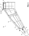
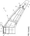
- the inert air assembly 12 may, for example and without limitation, be disposed at least partially in a wing 104, 106 of an aircraft 100, such as in a fairing of a wing 104, 106.
- an aircraft 100 includes one or more main fuel tanks 14, 16, 18, such as a left wing tank 14, a right wing tank 16, and/or a center tank 18. Additionally, aircraft 100 includes one or more surge tanks 20, 22, such as a left surge tank 20 and a right surge tank 22.
- the surge tanks 20, 22 may be configured to receive fuel from the main fuel tanks 14, 16, 18, such as if high temperatures cause fuel in the main tanks 14, 16, 18 to expand, fuel slosh due to maneuvering, and/or refuel overflow.
- the aircraft fuel inerting system 12 may be configured to provide inert air 34 to some or all of the tanks 14, 16, 18.
- the surge tanks 20, 22 may include one or more surge tank components 64, 66.
- the surge tanks 20, 22 may include one or more climb and dive valve 68, depressurization valve 70 (e.g., for refueling and emergency descent), a flame arrestor 72, and/or one or more drains/pressure relief valves 74.
- the surge tank components 64, 66 may be in fluid communication with the environment (e.g., ambient/outside air) and may be configured to vent air from the tanks 14, 16, 18 if the pressure in the tanks 14, 16, 18 is above a threshold and/or may be configured to receive external air if the pressure in the tanks 14, 16, 18 (or a pressure differential) is below a threshold.
- the surge tanks 20, 22 may be disposed at or about outer ends of the wings 104, 106 of an aircraft 100.
- the aircraft fuel tank inerting system 10 includes one or more fluid valves 24, 26, 28.
- an aircraft fuel tank inerting system 12 may include a fluid valve 24, 26 for each surge tank 20, 22, but a fluid valve 28 could be utilized with more than one surge tank 20, 22.
- a fluid valve 24, 26, 28 may be configured to control the flow of inert air 34 (from the inert air assembly 12) into the tanks 14, 16, 18.
- An inlet 76 of the fluid valve 24, 26, 28 may be in fluid communication with an outlet 62 of the inert air assembly 12.
- a first outlet 78 of the fluid valve 24, 26, 28 may be in fluid communication with a main/wing tank 14, 16, 18.
- a second outlet 80 of the fluid valve 24, 26, 28 may be fluid communication with a surge tank 20, 22.
- the fluid valve 24, 26, 28 may block fluid communication between the inlet 76, and the first and second outlets 78, 80 (e.g., may not provide inert air 34 to any of the tanks 14, 16, 18, 29, 22), such as to enable the execution of BIT (built-in-test) to check for latent failures of the fluid distribution system.
- the fluid valve 24, 26, 28 may provide fluid communication between the inlet 76 and the first outlet 78 (e.g., provide inert air 34 to a main/wing tank 14, 16, 18).
- the fluid valve 24, 26, 28 may provide fluid communication between the inlet 76 and the second outlet 80 (e.g., provide inert air 34 to a surge tank 20, 22).
- the fluid valve 24, 26, 28 may be disposed in a main tank 14, 16, 18, partially in a surge tank 20, 22, or entirely in a surge tank 20, 22.
- the ECU 30 is configured to control operation of the fluid valve(s) 24, 26, 28, such as between the closed, open, and bypass positions.
- the ECU 30 may operate a fluid valve 24, 26, 28 (e.g., the first fluid valve 24, the second fluid valve 26, and/or the third fluid valve 28) in a closed position if air in the fuel tanks 14, 16, 18 has a sufficiently low oxygen concentration and/or if the aircraft 100 is on the ground.
- the ECU 30 may be connected to a sensor 82 (e.g., a weight on wheels sensor) that indicates whether the aircraft 100 to which the ECU 30 is connected is on the ground. If the ECU 30 determines that the aircraft 100 is on the ground, the ECU 30 operates the fluid valve 24, 26, 28 in the closed position.
- the ECU 30 may operate the fluid valve in the closed position during a cruise phase of a flight if the tanks 14, 16, 18 reach a sufficient inert margin (e.g., oxygen concentration at about 14% or below).
- the ECU 30 may operate the fluid valve in the closed position for testing, such as built-in-test (BIT) functions, that may evaluate operation of one or more other valves 14, 16, 18 in the fuel tank inerting system 10.
- BIT built-in-test
- the ECU 30 may be configured to independently control the first fluid valve 24, the second fluid valve 26, and the third fluid valve 28.
- the ECU 30 may be connected to one or more sensors 84 that may be configured to obtain information about the tanks 14, 16, 18, such as, for example and without limitation, oxygen sensors that may provide information about the concentration of oxygen in the air in the tanks 14, 16, 18.
- the ECU 30 may operate the fluid valve 24, 26, 28 in an open/second position during a climb phase of a flight and/or during a cruise phase of the flight (e.g., if the tanks have not reached a sufficient inert margin).
- the fluid valve In the open position, the fluid valve may provide inert air 34 from the inert air assembly 12 to a tank 14, 16, 18 via one or more first fluid conduits 86.
- the inert air 34 may flow into the first fluid conduits 86 and may exit the first fluid conduits 86 into the tanks 14, 16, 18 at one or more locations along the first fluid conduits 86.
- the inert air 34 may mix with the tank air, which may have a higher oxygen concentration than the inert air 34, to reduce the oxygen concentration of the tank air, such as to a level below a threshold (e.g., 12% under 20,000 feet (6096 m), and 14% between 20,000 feet (6096 m) and a cruise ceiling of about 43,000 feet (13106 m)).
- a threshold e.g., 12% under 20,000 feet (6096 m), and 14% between 20,000 feet (6096 m) and a cruise ceiling of about 43,000 feet (13106 m)
- the ECU 30 may be configured to operate a fluid valve 24, 26, 28 in a bypass/third position. In the bypass position, the fluid valve 24, 26, 28 may provide inert air 34 from the inert air assembly 12 to a surge tank 20, 22.
- the ECU 30 may operate the fluid valve 24, 26, 28 in the bypass position during a descent phase of a flight and/or if the pressure in the tanks 14, 16, 18 is significantly lower than an ambient air pressure. In such circumstances, outside/ambient air may flow into the surge tank 20, 22 and then into the main tanks 14, 16, 18 to equalize the pressure in the main tanks, at least to some degree.
- the ambient air entering the surge tank 20, 22 may include a relatively high concentration of oxygen, such as about 20-22%.
- the fluid valve 24, 26, 28 may provide the inert air 34 to the surge tank 20, 22, and the inert air 34 may mix with the ambient air in the surge tank 20, 22 (e.g., the surge tank 20, 22 may act as a mixing chamber).
- the resulting mixed air may include a reduced oxygen concentration.
- the mixed air may include an oxygen concentration of about 14-16%.
- the mixed air may flow from the surge tank 20, 22 into second fluid conduits 88 that may be connected to one or more main tanks 14, 16, 18.
- the mixed air may flow through the second fluid conduits 88 and may exit the second fluid conduits 88 into the main tank(s) 14, 16, 18 at one or more locations along the second fluid conduits 88.
- the mixed air may continue to mix in the second fluid conduits 88.
- a first fluid valve 24 may be connected to the left wing tank 14 and the left surge tank 20
- a second fluid valve 26 may be connected to the right wing tank 16 and the right surge tank 22
- a third fluid valve 28 may be connected to the center tank 18 and one or both of the surge tanks 20, 22.
- the first fluid valve 24 and the second fluid valve 26 may include substantially the same configuration (e.g., with closed, open, and bypass positions).
- the third fluid valve 28 may include a different configuration than the first and second fluid valves 24, 26.
- the third fluid valve 28 may include a closed position and an open position and may not include a bypass position.
- the ECU 30 may operate the third fluid valve 28 in the open position to reduce the oxygen concentration in the center tank 18.
- the second fluid conduits 88 may be connected to the left surge tank 20 and the right surge tank 22.
- the second fluid conduit(s) 88 connected to the first surge tank 20 may provide fluid communication from the first surge tank 20 to the left wing tank 14 and/or to the center tank 18.
- the second fluid conduit(s) 88 connected to the second surge tank 22 may provide fluid communication from the second surge tank 22 to the right wing tank 16 and/or to the center tank 18.
- the ECU 30 may operate the first fluid valve 24 and the second fluid valve 26 in bypass positions such that mixed air is provided from the left surge tank 20 and the right surge tank 22 to the main tanks 14, 16, 18 via the second fluid conduits 88.
- a method of inerting aircraft fuel tanks includes providing an aircraft 100 having an aircraft fuel tank inerting system 10, at least one fuel tank 14, 16, 18, and at least one surge tank 20, 22.
- the aircraft fuel tank inerting system 10 includes at least one fluid valve 24, 26, 28 and an inert air assembly 12.
- the method includes operating the fluid valve(s) 24, 26, 28 in an open position during a climb phase of a flight to provide inert air 34 from the inert air assembly 12 to the fuel tank(s) 14, 16, 18.
- the method includes operating the fluid valve(s) 24, 26, 28 in a closed position during a cruise phase of the flight if the fuel tank(s) 14, 16, 18 has achieved an inert margin above a threshold.
- the method includes operating the fluid valve(s) 24, 26, 28 in a bypass position during a descent phase of the flight to provide inert air 34 to the surge tank 20, 22.
- the method may include mixing inert air 34 from the inert air assembly 12 with ambient air in the surge tank 20, 22 to form mixed air.
- the mixed air may continue to mix in a second fluid conduit 88 that may be connected to the surge tank 20, 22 and the fuel tank 14, 16, 18.
- the method may include providing the mixed air to the fuel tank 14, 16, 18.
- the method may include operating the (first) fluid valve 24 and a second fluid valve 26 in bypass positions to provide mixed air from the (first) surge tank 20 to the (left wing) fuel tank 14, from a second surge tank 22 to a second (right wing) fuel tank 16, and/or from both the (first) surge tank 20 and the second surge tank 22, via second fluid conduits 88, to a third (center) fuel tank 18.
- the method includes operating the fluid valve(s) 24, 26, 28 in the closed position if the aircraft 100 is on the ground.
- One or more portions of the method may be implemented/carried out via the ECU 30.
- outside/ambient air may be provided directly to the main tanks from the surge tank, and inert air may be separately provided to the main tanks.
- the ambient air may be provided to the main tanks at one or more discrete locations.
- the ambient air may include high levels of oxygen, the flow of ambient air into the tanks may result in areas/pockets of higher concentrations of oxygen in the main tank, which may be referred to as "hot spots".
- the air in the main tank may be maintained at an even lower level of oxygen to compensate for ambient air, which may involve providing additional inert air to the main tank.
- Providing additional inert air to the main tank may involve increasing the capacity and/or duty cycle of an inert air assembly (e.g., increasing the number of ASMs).
- ambient air may not be provided directly to the main tanks 14, 16, 18. Instead, the ambient air may be pre-mixed with inert air 34 such that the air entering the main tanks 14, 16, 18 (e.g., mixed air) has a reduced oxygen concentration, which may limit and/or prevent the generation of hot spots.
- the maximum capacity of the inert air assembly may be reduced, which may reduce the weight of the inert air assembly (e.g., the inert air assembly may include fewer ASMs which may weigh about 30 lbs. each).
- the duty cycle of the inert air assembly 12 may be reduced as a result of a lower demand for inert air, which may increase the life cycle of the inert air assembly 12.
- an ECU 30 may include an electronic controller and/or include an electronic processor, such as a programmable microprocessor and/or microcontroller.
- an ECU 30 may include, for example, an application specific integrated circuit (ASIC).
- An ECU 30 may include a central processing unit (CPU), a memory (e.g., a non-transitory computer-readable storage medium), and/or an input/output (I/O) interface.
- An ECU 30 may be configured to perform various functions, including those described in greater detail herein, with appropriate programming instructions and/or code embodied in software, hardware, and/or other medium.
- an ECU 30 may include a plurality of controllers.
- an ECU may be connected to a display, such as a touchscreen display.
- references to a single element are not necessarily so limited and may include one or more of such element.
- Any directional references e.g., plus, minus, upper, lower, upward, downward, left, right, leftward, rightward, top, bottom, above, below, vertical, horizontal, clockwise, and counterclockwise
- Any directional references are only used for identification purposes to aid the reader's understanding of the present disclosure, and do not create limitations, particularly as to the position, orientation, or use of embodiments.
- joinder references are to be construed broadly and may include intermediate members between a connection of elements and relative movement between elements. As such, joinder references do not necessarily imply that two elements are directly connected/coupled and in fixed relation to each other.
- the use of "e.g.” in the specification is to be construed broadly and is used to provide non-limiting examples of embodiments of the disclosure, and the disclosure is not limited to such examples.
- an electronic control unit may include a conventional processing apparatus known in the art, which may be capable of executing preprogrammed instructions stored in an associated memory, all performing in accordance with the functionality described herein.
- a system or processor may further be of the type having ROM, RAM, RAM and ROM, and/or a combination of non-volatile and volatile memory so that any software may be stored and yet allow storage and processing of dynamically produced data and/or signals.
- an article of manufacture in accordance with this disclosure may include a non-transitory computer-readable storage medium having a computer program encoded thereon for implementing logic and other functionality described herein.
- the computer program may include code to perform one or more of the methods disclosed herein.
- Such embodiments may be configured to execute via one or more processors, such as multiple processors that are integrated into a single system or are distributed over and connected together through a communications network, and the communications network may be wired and/or wireless.
- Code for implementing one or more of the features described in connection with one or more embodiments may, when executed by a processor, cause a plurality of transistors to change from a first state to a second state.
- a specific pattern of change (e.g., which transistors change state and which transistors do not), may be dictated, at least partially, by the logic and/or code.
Landscapes
- Engineering & Computer Science (AREA)
- Aviation & Aerospace Engineering (AREA)
- Filling Or Discharging Of Gas Storage Vessels (AREA)
- Loading And Unloading Of Fuel Tanks Or Ships (AREA)
- Cooling, Air Intake And Gas Exhaust, And Fuel Tank Arrangements In Propulsion Units (AREA)
Claims (12)
- Flugzeugtreibstofftank-Inertisierungssystem (10), umfassend:mindestens einen Treibstofftank (14, 16, 18);mindestens einen Ausgleichsbehälter (20, 22);eine Inertluftanordnung (12);mindestens ein Fluidventil (24, 26, 28) in Fluidverbindung mit dem mindestens einen Treibstofftank (14, 16, 18), dem mindestens einen Ausgleichsbehälter (20, 22) und der Inertluftanordnung (12); undeine elektronische Steuereinheit (30);wobei die elektronische Steuereinheit (30) konfiguriert ist, um das mindestens eine Fluidventil (24, 26, 28) zu steuern, um Inertluft (34) aus der Inertluftanordnung (12) wahlweise dem mindestens einen Treibstofftank oder dem mindestens einen Ausgleichbehälter bereitzustellen;dadurch gekennzeichnet, dass:
die elektronische Steuereinheit (30) ferner konfiguriert ist, um das mindestens eine Fluidventil (24, 26, 28) zu schließen, wenn die elektronische Steuereinheit (30) bestimmt, dass das Flugzeug (100), mit dem die elektronische Steuereinheit (30) verbunden ist, am Boden ist. - Flugzeugtreibstofftank-Inertisierungssystem (10) nach Anspruch 1, wobei die elektronische Steuereinheit (30) konfiguriert ist, um das mindestens eine Fluidventil (24, 26, 28) zu steuern, um die Inertluft (34) aus der Inertluftanordnung (12) dem mindestens einen Treibstofftank (14, 16, 18) während einer Steigflugphase bereitzustellen, und das mindestens eine Fluidventil (24, 26, 28) zu steuern, um die Inertluft (34) aus der Inertluftanordnung (12) dem mindestens einen Ausgleichsbehälter (20, 22) während einer Sinkflugphase bereitzustellen.
- Flugzeugtreibstofftank-Inertisierungssystem (10) nach Anspruch 2, wobei die elektronische Steuereinheit (30) konfiguriert ist, um das mindestens eine Fluidventil (24, 26, 28) derart zu steuern, dass während der Sinkflugphase Mischluft, die aus dem mindestens einen Ausgleichsbehälter (20, 22) dem mindestens einen Treibstofftank (14, 16, 18) bereitgestellt wird, weniger als etwa 20 % Sauerstoff enthält.
- Flugzeugtreibstofftank-Inertisierungssystem (10) nach Anspruch 2, wobei die elektronische Steuereinheit (30) konfiguriert ist, um das mindestens eine Fluidventil (24, 26, 28) während einer Reiseflugphase in einer geschlossenen Position zu steuern, wenn der mindestens ein Treibstofftank (14, 16, 18) eine Inertgrenze über einem Schwellenwert erreicht hat, um eine Sauerstoffkonzentration bei oder unter einem vorbestimmten Wert bereitzustellen.
- Flugzeugtreibstofftank-Inertisierungssystem (10) nach Anspruch 1, wobei der mindestens eine Treibstofftank (14, 16, 18) einen linken Treibstoffflügeltank (14), einen rechten Treibstoffflügeltank (16) und einen mittleren Treibstofftank (18) einschließt, wobei das mindestens eine Fluidventil (24, 26, 28) ein erstes Fluidventil (24), ein zweites Fluidventil (26) und ein drittes Fluidventil (28) einschließt und der mindestens eine Ausgleichsbehälter (20, 22) einen linken Ausgleichsbehälter (20) und einen rechten Ausgleichsbehälter (22) einschließt.
- Flugzeugtreibstofftank-Inertisierungssystem (10) nach Anspruch 5, wobei die elektronische Steuereinheit (30) zu Folgendem konfiguriert ist:
Betätigen des ersten Fluidventils (24), des zweiten Fluidventils (26) und/oder des dritten Fluidventils (28) in einer offenen Position während einer Steigflugphase, um Inertluft (34) dem linken Treibstoffflügeltank (14), dem rechten Treibstoffflügeltank (16) und/oder dem mittleren Treibstofftank (18) bereitzustellen; Betätigen des ersten Fluidventils (24), des zweiten Fluidventils (26) und/oder des dritten Fluidventils (28) in einer geschlossenen Position, wenn der linke Treibstoffflügeltank (14), der rechte Treibstoffflügeltank (16) und/oder der mittlere Treibstofftank (18) eine Inertgrenze über einem Schwellenwert erreicht hat, um eine Sauerstoffkonzentration bei oder unter einem vorbestimmten Wert bereitzustellen; und Betätigen des ersten Fluidventils (24) und/oder des zweiten Fluidventils (26) in einer Bypassposition während einer Sinkflugphase, um die Fluidverbindung zwischen der Inertluftanordnung (12) und dem linken Treibstoffflügeltank (14), dem rechten Treibstoffflügeltank (16) und/oder dem mittleren Treibstofftank (18) umzuleiten und stattdessen Inertluft (34) dem linken Ausgleichsbehälter (20) und/oder dem rechten Ausgleichsbehälter (22) bereitzustellen. - Verfahren zum Inertisieren eines oder mehrerer Flugzeugtreibstofftanks, wobei das Verfahren Folgendes umfasst:Betätigen mindestens eines Fluidventils (24, 26, 28) eines Flugzeugs (100) in einer offenen Position während einer Steigflugphase, um Inertluft (34) mindestens einem Treibstofftank (14, 16, 18) des Flugzeugs (100) aus einer Inertluftanordnung (12) des Flugzeugs (100) bereitzustellen; Betätigen des mindestens einen Fluidventils (24, 26, 28) in einer geschlossenen Position während einer Reiseflugphase, wenn der mindestens eine Treibstofftank (24, 26, 28) eine Inertgrenze über einem Schwellenwert erreicht hat, um eine Sauerstoffkonzentration bei oder unter einem vorbestimmten Wert bereitzustellen;Betätigen des mindestens einen Fluidventils (24, 26, 28) in einer Bypassposition während einer Sinkflugphase, um die Fluidverbindung zwischen der Inertluftanordnung (12) und dem mindestens einen Treibstofftank (14, 16, 18) umzuleiten und stattdessen mindestens einem Ausgleichsbehälter (20, 22) des Flugzeugs (100) Inertluft bereitzustellen; undBetätigen des mindestens einen Fluidventils (24, 26, 28) in der geschlossenen Position, wenn bestimmt wird, dass sich das Flugzeug (100) am Boden befindet.
- Verfahren nach Anspruch 7, einschließend:Mischen von Inertluft (34) aus der Inertluftanordnung (12) mit Umgebungsluft in dem mindestens einenAusgleichsbehälter (20, 22), um Mischluft zu bilden; undBereitstellen der Mischluft an dem mindestens einen Treibstofftank (14, 16, 18).
- Flugzeug (100), umfassend:mindestens ein Triebwerk (102);einen linken Flügel (104) und einen rechten Flügel (106);ein Flugzeugtreibstofftank-Inertisierungssystem, wie es in Anspruch 1 definiert ist, umfassend:einen linken Treibstoffflügeltank (14) im linken Flügel (104) und einen rechten Treibstoffflügeltank (16) im rechten Flügel (106);einen linken Ausgleichsbehälter (20) im linken Flügel (104) und einen rechten Ausgleichsbehälter (20) im rechten Flügel (106);eine Inertluftanordnung (12);ein erstes Fluidventil (24), das mit dem linken Treibstofffügeltank (14), dem linken Ausgleichsbehälter (20) und der Inertluftanordnung (12) verbunden ist;ein zweites Fluidventil (26), das mit dem rechten Treibstoffflügeltank (16), dem rechten Ausgleichsbehälter (22) und der Inertluftanordnung (12) verbunden ist; undeine elektronische Steuereinheit (30);wobei die elektronische Steuereinheit (30) konfiguriert ist, um das erste Fluidventil (24) zu steuern, um Inertluft (34) aus der Inertluftanordnung (12) dem linken Treibstoffflügeltank (14) oder dem linken Ausgleichsbehälter (20) bereitzustellen, und das zweite Fluidventil (26) konfiguriert ist, um Inertluft (34) aus der Inertluftanordnung (12) dem rechten Treibstoffflügeltank (26) oder dem rechten Ausgleichsbehälter (22) bereitzustellen;wobei die elektronische Steuereinheit (30) ferner konfiguriert ist, um das erste Fluidventil (24) und/oder das zweite Fluidventil (26) zu schließen, wenn die elektronische Steuereinheit (30) bestimmt, dass das Flugzeug (100), mit dem die elektronische Steuereinheit (30) verbunden ist, sich am Boden befindet.
- Flugzeug (100) nach Anspruch 9, wobei die elektronische Steuereinheit (30) konfiguriert ist, um das erste Fluidventil (24) und/oder das zweite Fluidventil (26) zu steuern, um die Inertluft (34) aus der Inertluftanordnung (12) dem linken Treibstoffflügeltank (14) und/oder dem rechten Treibstoffflügeltank (16) während einer Steigflugphase bereitzustellen und das erste Fluidventil (24) und/oder das zweite Fluidventil (26) zu steuern, um die Inertluft (34) aus der Inertluftanordnung (12) dem linken Ausgleichsbehälter (20) und/oder dem rechten Ausgleichsbehälter (22) während einer Sinkflugphase bereitzustellen.
- Flugzeug (100) nach Anspruch 10, wobei die elektronische Steuereinheit (30) konfiguriert ist, um das erste Fluidventil (24) und/oder das zweite Fluidventil (26) in einer geschlossenen Position während einer Reiseflugphase zu betreiben, wenn der linke Treibstoffflügeltank (14) und/oder der rechte Treibstoffflügeltank (18) eine Inertgrenze über einem Schwellenwert erreicht hat, um eine Sauerstoffkonzentration bei oder unter einem vorbestimmten Wert bereitzustellen.
- Flugzeug (100) nach Anspruch 10, ferner umfassend einen mittleren Treibstofftank (18) und ein drittes Fluidventil (28), wobei die elektronische Steuereinheit (30) konfiguriert ist, um das dritte Fluidventil (28) zu steuern, um Inertluft (34) aus der Inertluftanordnung (12) dem mittleren Treibstofftank (18) bereitzustellen, wobei die elektronische Steuereinheit (30) konfiguriert ist, um das dritte Fluidventil (28) zu steuern, um die Inertluft (34) aus der Inertluftanordnung (12) dem mittleren Treibstofftank (18) während einer Steigflugphase eines Flight-and-Fix-Abgleichs bereitzustellen, und um das dritte Fluidventil (28) in einer geschlossenen Position während einer Reiseflugphase zu betreiben, wenn der mittlere Treibstofftanktank (18) eine Inertgrenze über einem Schwellenwert erreicht hat, um eine Sauerstoffkonzentration bei oder unter einem vorbestimmten Wert bereitzustellen.
Applications Claiming Priority (1)
| Application Number | Priority Date | Filing Date | Title |
|---|---|---|---|
| US201962827321P | 2019-04-01 | 2019-04-01 |
Publications (2)
| Publication Number | Publication Date |
|---|---|
| EP3718905A1 EP3718905A1 (de) | 2020-10-07 |
| EP3718905B1 true EP3718905B1 (de) | 2022-06-08 |
Family
ID=70154220
Family Applications (1)
| Application Number | Title | Priority Date | Filing Date |
|---|---|---|---|
| EP20167423.1A Active EP3718905B1 (de) | 2019-04-01 | 2020-03-31 | Inertisierungssystem für einen flugzeugtreibstofftank |
Country Status (3)
| Country | Link |
|---|---|
| US (2) | US11618582B2 (de) |
| EP (1) | EP3718905B1 (de) |
| CN (1) | CN111792046B (de) |
Families Citing this family (3)
| Publication number | Priority date | Publication date | Assignee | Title |
|---|---|---|---|---|
| US11618582B2 (en) * | 2019-04-01 | 2023-04-04 | Eaton Intelligent Power Limited | Aircraft fuel tank inerting system |
| CN113734455B (zh) * | 2021-10-12 | 2023-02-03 | 中国商用飞机有限责任公司 | 具有富氮气体储存功能的惰化系统 |
| CN115743571B (zh) * | 2022-11-21 | 2025-08-29 | 中国商用飞机有限责任公司 | 一种燃油箱通气系统 |
Family Cites Families (15)
| Publication number | Priority date | Publication date | Assignee | Title |
|---|---|---|---|---|
| GB0001649D0 (en) | 2000-01-26 | 2000-12-20 | British Aerospace | A fuel inerting system |
| US6997970B2 (en) | 2002-06-25 | 2006-02-14 | Carleton Life Support Systems, Inc. | Oxygen/inert gas generator |
| US7007893B2 (en) | 2004-02-10 | 2006-03-07 | The Boeing Company | Methods and systems for controlling flammability control systems in aircraft and other vehicles |
| US7152635B2 (en) | 2004-02-10 | 2006-12-26 | The Boeing Company | Commercial aircraft on-board inerting system |
| US8074932B2 (en) | 2009-09-21 | 2011-12-13 | Hamilton Sundstrand Corporation | NEA distribution system for OBIGGS applications |
| GB201006213D0 (en) | 2010-04-14 | 2010-06-02 | Airbus Operations Ltd | Fuel system and method |
| GB201101463D0 (en) | 2011-01-28 | 2011-03-16 | Airbus Operations Ltd | Aircraft fuel system |
| FR2987822B1 (fr) | 2012-03-12 | 2014-04-11 | Air Liquide | Dispositif d'inertage, reservoir et aeronef munis d'un tel dispositif et procede correspondant |
| US9072921B2 (en) * | 2012-10-24 | 2015-07-07 | Hamilton Sundstrand Corporation | Thermodynamically-optimized advanced fire suppression system |
| JP6117647B2 (ja) * | 2013-08-05 | 2017-04-19 | 三菱航空機株式会社 | 航空機の燃料システム、航空機 |
| GB2528109A (en) | 2014-07-10 | 2016-01-13 | Airbus Operations Ltd | Aircraft fuel system |
| EP3405393B1 (de) * | 2016-01-22 | 2023-05-31 | Parker-Hannifin Corporation | Katalytisches inertisierungssystem fèr ein flugzeug mit mehreren treibstofftanks |
| US10648382B2 (en) | 2016-10-05 | 2020-05-12 | Parker-Hannifin Corporation | Inerting and venting system |
| US10737800B2 (en) * | 2017-06-07 | 2020-08-11 | Parker-Hannifin Corporation | Catalytic inerting system architecture and control methods for increased fuel tank safety |
| US11618582B2 (en) * | 2019-04-01 | 2023-04-04 | Eaton Intelligent Power Limited | Aircraft fuel tank inerting system |
-
2020
- 2020-03-31 US US16/835,540 patent/US11618582B2/en active Active
- 2020-03-31 EP EP20167423.1A patent/EP3718905B1/de active Active
- 2020-04-01 CN CN202010251033.9A patent/CN111792046B/zh active Active
-
2023
- 2023-03-15 US US18/184,238 patent/US12240623B2/en active Active
Also Published As
| Publication number | Publication date |
|---|---|
| CN111792046A (zh) | 2020-10-20 |
| US11618582B2 (en) | 2023-04-04 |
| CN111792046B (zh) | 2025-01-03 |
| US20230294839A1 (en) | 2023-09-21 |
| EP3718905A1 (de) | 2020-10-07 |
| US20200307821A1 (en) | 2020-10-01 |
| US12240623B2 (en) | 2025-03-04 |
Similar Documents
| Publication | Publication Date | Title |
|---|---|---|
| US12240623B2 (en) | Aircraft fuel tank inerting system | |
| EP2837564B1 (de) | Duales Wärmetauscher-Inertisierungssystem für einen Kraftstoffbehälter | |
| JP5275302B2 (ja) | 燃料タンク内のアレッジの生成方法および装置 | |
| RU2706753C1 (ru) | Система каталитического инертирования для летательного аппарата с несколькими топливными баками | |
| CN104843188B (zh) | 一种基于催化氧化技术的飞行器燃油箱惰化装置 | |
| US9511874B2 (en) | Inerting device, tank and aircraft provided with such a device, and corresponding method | |
| BR112017010916B1 (pt) | Sistema de célula de combustível de aeronave, e processo para diluir uma atmosfera de gás contendo hidrogênio | |
| EP2634092B1 (de) | Aktive Strömungsregelung in Flugzeugen | |
| EP3601871B1 (de) | Gasaufbewahrung in mehreren behältern | |
| US10286235B2 (en) | Systems and methods for flammability reduction and ventilation using nitrogen-enriched gas for transportation vehicle protection | |
| US11780601B2 (en) | Temperature control system for fuel tank inerting system | |
| US20210086908A1 (en) | Aircraft fuel tank pressurization systems and methods | |
| RU2741154C2 (ru) | Способ управления отношением чистота/расход инертного газа, нагнетаемого в топливный бак, а также система инертирования для осуществления способа | |
| US11540662B2 (en) | Vent valve flow fuse | |
| EP3808658B1 (de) | Klimasteuerungsanlage | |
| US20160009408A1 (en) | Nitrogen enriched air supply system and aircraft | |
| US11085713B2 (en) | Heat exchanger | |
| Bian | Civil Aircraft Cabin Pressure System Decompression Calculation and Analysis | |
| KR20150100128A (ko) | 해양 로딩암의 설계방법 | |
| Karami et al. | Civil Aircraft Inerting and venting System Design | |
| CN120191502A (zh) | 一种大型集装箱船压载舱局部共轨透气系统及其设计方法 | |
| Nobbs | PSC implementation and integration | |
| Barrie | UAV Safety- Beyond Control | |
| Skoog | Life support system development in West Germany | |
| KR20140101087A (ko) | 선박의 균형조절장치 및 이를 갖춘 선박 |
Legal Events
| Date | Code | Title | Description |
|---|---|---|---|
| PUAI | Public reference made under article 153(3) epc to a published international application that has entered the european phase |
Free format text: ORIGINAL CODE: 0009012 |
|
| STAA | Information on the status of an ep patent application or granted ep patent |
Free format text: STATUS: REQUEST FOR EXAMINATION WAS MADE |
|
| 17P | Request for examination filed |
Effective date: 20200331 |
|
| AK | Designated contracting states |
Kind code of ref document: A1 Designated state(s): AL AT BE BG CH CY CZ DE DK EE ES FI FR GB GR HR HU IE IS IT LI LT LU LV MC MK MT NL NO PL PT RO RS SE SI SK SM TR |
|
| AX | Request for extension of the european patent |
Extension state: BA ME |
|
| GRAP | Despatch of communication of intention to grant a patent |
Free format text: ORIGINAL CODE: EPIDOSNIGR1 |
|
| STAA | Information on the status of an ep patent application or granted ep patent |
Free format text: STATUS: GRANT OF PATENT IS INTENDED |
|
| GRAJ | Information related to disapproval of communication of intention to grant by the applicant or resumption of examination proceedings by the epo deleted |
Free format text: ORIGINAL CODE: EPIDOSDIGR1 |
|
| INTG | Intention to grant announced |
Effective date: 20211014 |
|
| STAA | Information on the status of an ep patent application or granted ep patent |
Free format text: STATUS: REQUEST FOR EXAMINATION WAS MADE |
|
| INTC | Intention to grant announced (deleted) | ||
| GRAP | Despatch of communication of intention to grant a patent |
Free format text: ORIGINAL CODE: EPIDOSNIGR1 |
|
| STAA | Information on the status of an ep patent application or granted ep patent |
Free format text: STATUS: GRANT OF PATENT IS INTENDED |
|
| INTG | Intention to grant announced |
Effective date: 20211217 |
|
| GRAS | Grant fee paid |
Free format text: ORIGINAL CODE: EPIDOSNIGR3 |
|
| GRAA | (expected) grant |
Free format text: ORIGINAL CODE: 0009210 |
|
| STAA | Information on the status of an ep patent application or granted ep patent |
Free format text: STATUS: THE PATENT HAS BEEN GRANTED |
|
| AK | Designated contracting states |
Kind code of ref document: B1 Designated state(s): AL AT BE BG CH CY CZ DE DK EE ES FI FR GB GR HR HU IE IS IT LI LT LU LV MC MK MT NL NO PL PT RO RS SE SI SK SM TR |
|
| REG | Reference to a national code |
Ref country code: AT Ref legal event code: REF Ref document number: 1496777 Country of ref document: AT Kind code of ref document: T Effective date: 20220615 Ref country code: CH Ref legal event code: EP |
|
| REG | Reference to a national code |
Ref country code: DE Ref legal event code: R096 Ref document number: 602020003425 Country of ref document: DE |
|
| REG | Reference to a national code |
Ref country code: IE Ref legal event code: FG4D |
|
| REG | Reference to a national code |
Ref country code: LT Ref legal event code: MG9D |
|
| REG | Reference to a national code |
Ref country code: NL Ref legal event code: MP Effective date: 20220608 |
|
| PG25 | Lapsed in a contracting state [announced via postgrant information from national office to epo] |
Ref country code: SE Free format text: LAPSE BECAUSE OF FAILURE TO SUBMIT A TRANSLATION OF THE DESCRIPTION OR TO PAY THE FEE WITHIN THE PRESCRIBED TIME-LIMIT Effective date: 20220608 Ref country code: NO Free format text: LAPSE BECAUSE OF FAILURE TO SUBMIT A TRANSLATION OF THE DESCRIPTION OR TO PAY THE FEE WITHIN THE PRESCRIBED TIME-LIMIT Effective date: 20220908 Ref country code: LT Free format text: LAPSE BECAUSE OF FAILURE TO SUBMIT A TRANSLATION OF THE DESCRIPTION OR TO PAY THE FEE WITHIN THE PRESCRIBED TIME-LIMIT Effective date: 20220608 Ref country code: HR Free format text: LAPSE BECAUSE OF FAILURE TO SUBMIT A TRANSLATION OF THE DESCRIPTION OR TO PAY THE FEE WITHIN THE PRESCRIBED TIME-LIMIT Effective date: 20220608 Ref country code: GR Free format text: LAPSE BECAUSE OF FAILURE TO SUBMIT A TRANSLATION OF THE DESCRIPTION OR TO PAY THE FEE WITHIN THE PRESCRIBED TIME-LIMIT Effective date: 20220909 Ref country code: FI Free format text: LAPSE BECAUSE OF FAILURE TO SUBMIT A TRANSLATION OF THE DESCRIPTION OR TO PAY THE FEE WITHIN THE PRESCRIBED TIME-LIMIT Effective date: 20220608 Ref country code: ES Free format text: LAPSE BECAUSE OF FAILURE TO SUBMIT A TRANSLATION OF THE DESCRIPTION OR TO PAY THE FEE WITHIN THE PRESCRIBED TIME-LIMIT Effective date: 20220608 Ref country code: BG Free format text: LAPSE BECAUSE OF FAILURE TO SUBMIT A TRANSLATION OF THE DESCRIPTION OR TO PAY THE FEE WITHIN THE PRESCRIBED TIME-LIMIT Effective date: 20220908 |
|
| REG | Reference to a national code |
Ref country code: AT Ref legal event code: MK05 Ref document number: 1496777 Country of ref document: AT Kind code of ref document: T Effective date: 20220608 |
|
| PG25 | Lapsed in a contracting state [announced via postgrant information from national office to epo] |
Ref country code: RS Free format text: LAPSE BECAUSE OF FAILURE TO SUBMIT A TRANSLATION OF THE DESCRIPTION OR TO PAY THE FEE WITHIN THE PRESCRIBED TIME-LIMIT Effective date: 20220608 Ref country code: LV Free format text: LAPSE BECAUSE OF FAILURE TO SUBMIT A TRANSLATION OF THE DESCRIPTION OR TO PAY THE FEE WITHIN THE PRESCRIBED TIME-LIMIT Effective date: 20220608 |
|
| PG25 | Lapsed in a contracting state [announced via postgrant information from national office to epo] |
Ref country code: NL Free format text: LAPSE BECAUSE OF FAILURE TO SUBMIT A TRANSLATION OF THE DESCRIPTION OR TO PAY THE FEE WITHIN THE PRESCRIBED TIME-LIMIT Effective date: 20220608 |
|
| PG25 | Lapsed in a contracting state [announced via postgrant information from national office to epo] |
Ref country code: SM Free format text: LAPSE BECAUSE OF FAILURE TO SUBMIT A TRANSLATION OF THE DESCRIPTION OR TO PAY THE FEE WITHIN THE PRESCRIBED TIME-LIMIT Effective date: 20220608 Ref country code: SK Free format text: LAPSE BECAUSE OF FAILURE TO SUBMIT A TRANSLATION OF THE DESCRIPTION OR TO PAY THE FEE WITHIN THE PRESCRIBED TIME-LIMIT Effective date: 20220608 Ref country code: RO Free format text: LAPSE BECAUSE OF FAILURE TO SUBMIT A TRANSLATION OF THE DESCRIPTION OR TO PAY THE FEE WITHIN THE PRESCRIBED TIME-LIMIT Effective date: 20220608 Ref country code: PT Free format text: LAPSE BECAUSE OF FAILURE TO SUBMIT A TRANSLATION OF THE DESCRIPTION OR TO PAY THE FEE WITHIN THE PRESCRIBED TIME-LIMIT Effective date: 20221010 Ref country code: EE Free format text: LAPSE BECAUSE OF FAILURE TO SUBMIT A TRANSLATION OF THE DESCRIPTION OR TO PAY THE FEE WITHIN THE PRESCRIBED TIME-LIMIT Effective date: 20220608 Ref country code: CZ Free format text: LAPSE BECAUSE OF FAILURE TO SUBMIT A TRANSLATION OF THE DESCRIPTION OR TO PAY THE FEE WITHIN THE PRESCRIBED TIME-LIMIT Effective date: 20220608 Ref country code: AT Free format text: LAPSE BECAUSE OF FAILURE TO SUBMIT A TRANSLATION OF THE DESCRIPTION OR TO PAY THE FEE WITHIN THE PRESCRIBED TIME-LIMIT Effective date: 20220608 |
|
| PG25 | Lapsed in a contracting state [announced via postgrant information from national office to epo] |
Ref country code: PL Free format text: LAPSE BECAUSE OF FAILURE TO SUBMIT A TRANSLATION OF THE DESCRIPTION OR TO PAY THE FEE WITHIN THE PRESCRIBED TIME-LIMIT Effective date: 20220608 Ref country code: IS Free format text: LAPSE BECAUSE OF FAILURE TO SUBMIT A TRANSLATION OF THE DESCRIPTION OR TO PAY THE FEE WITHIN THE PRESCRIBED TIME-LIMIT Effective date: 20221008 |
|
| REG | Reference to a national code |
Ref country code: DE Ref legal event code: R097 Ref document number: 602020003425 Country of ref document: DE |
|
| PG25 | Lapsed in a contracting state [announced via postgrant information from national office to epo] |
Ref country code: AL Free format text: LAPSE BECAUSE OF FAILURE TO SUBMIT A TRANSLATION OF THE DESCRIPTION OR TO PAY THE FEE WITHIN THE PRESCRIBED TIME-LIMIT Effective date: 20220608 |
|
| PLBE | No opposition filed within time limit |
Free format text: ORIGINAL CODE: 0009261 |
|
| STAA | Information on the status of an ep patent application or granted ep patent |
Free format text: STATUS: NO OPPOSITION FILED WITHIN TIME LIMIT |
|
| PG25 | Lapsed in a contracting state [announced via postgrant information from national office to epo] |
Ref country code: DK Free format text: LAPSE BECAUSE OF FAILURE TO SUBMIT A TRANSLATION OF THE DESCRIPTION OR TO PAY THE FEE WITHIN THE PRESCRIBED TIME-LIMIT Effective date: 20220608 |
|
| 26N | No opposition filed |
Effective date: 20230310 |
|
| PG25 | Lapsed in a contracting state [announced via postgrant information from national office to epo] |
Ref country code: SI Free format text: LAPSE BECAUSE OF FAILURE TO SUBMIT A TRANSLATION OF THE DESCRIPTION OR TO PAY THE FEE WITHIN THE PRESCRIBED TIME-LIMIT Effective date: 20220608 |
|
| P01 | Opt-out of the competence of the unified patent court (upc) registered |
Effective date: 20230521 |
|
| PG25 | Lapsed in a contracting state [announced via postgrant information from national office to epo] |
Ref country code: MC Free format text: LAPSE BECAUSE OF FAILURE TO SUBMIT A TRANSLATION OF THE DESCRIPTION OR TO PAY THE FEE WITHIN THE PRESCRIBED TIME-LIMIT Effective date: 20220608 |
|
| REG | Reference to a national code |
Ref country code: CH Ref legal event code: PL |
|
| REG | Reference to a national code |
Ref country code: BE Ref legal event code: MM Effective date: 20230331 |
|
| PG25 | Lapsed in a contracting state [announced via postgrant information from national office to epo] |
Ref country code: LU Free format text: LAPSE BECAUSE OF NON-PAYMENT OF DUE FEES Effective date: 20230331 |
|
| REG | Reference to a national code |
Ref country code: IE Ref legal event code: MM4A |
|
| PG25 | Lapsed in a contracting state [announced via postgrant information from national office to epo] |
Ref country code: LI Free format text: LAPSE BECAUSE OF NON-PAYMENT OF DUE FEES Effective date: 20230331 Ref country code: IT Free format text: LAPSE BECAUSE OF FAILURE TO SUBMIT A TRANSLATION OF THE DESCRIPTION OR TO PAY THE FEE WITHIN THE PRESCRIBED TIME-LIMIT Effective date: 20220608 Ref country code: IE Free format text: LAPSE BECAUSE OF NON-PAYMENT OF DUE FEES Effective date: 20230331 Ref country code: CH Free format text: LAPSE BECAUSE OF NON-PAYMENT OF DUE FEES Effective date: 20230331 |
|
| PG25 | Lapsed in a contracting state [announced via postgrant information from national office to epo] |
Ref country code: BE Free format text: LAPSE BECAUSE OF NON-PAYMENT OF DUE FEES Effective date: 20230331 |
|
| PG25 | Lapsed in a contracting state [announced via postgrant information from national office to epo] |
Ref country code: BG Free format text: LAPSE BECAUSE OF FAILURE TO SUBMIT A TRANSLATION OF THE DESCRIPTION OR TO PAY THE FEE WITHIN THE PRESCRIBED TIME-LIMIT Effective date: 20220608 |
|
| PG25 | Lapsed in a contracting state [announced via postgrant information from national office to epo] |
Ref country code: BG Free format text: LAPSE BECAUSE OF FAILURE TO SUBMIT A TRANSLATION OF THE DESCRIPTION OR TO PAY THE FEE WITHIN THE PRESCRIBED TIME-LIMIT Effective date: 20220608 |
|
| PG25 | Lapsed in a contracting state [announced via postgrant information from national office to epo] |
Ref country code: CY Free format text: LAPSE BECAUSE OF FAILURE TO SUBMIT A TRANSLATION OF THE DESCRIPTION OR TO PAY THE FEE WITHIN THE PRESCRIBED TIME-LIMIT; INVALID AB INITIO Effective date: 20200331 |
|
| PG25 | Lapsed in a contracting state [announced via postgrant information from national office to epo] |
Ref country code: HU Free format text: LAPSE BECAUSE OF FAILURE TO SUBMIT A TRANSLATION OF THE DESCRIPTION OR TO PAY THE FEE WITHIN THE PRESCRIBED TIME-LIMIT; INVALID AB INITIO Effective date: 20200331 |
|
| PG25 | Lapsed in a contracting state [announced via postgrant information from national office to epo] |
Ref country code: TR Free format text: LAPSE BECAUSE OF FAILURE TO SUBMIT A TRANSLATION OF THE DESCRIPTION OR TO PAY THE FEE WITHIN THE PRESCRIBED TIME-LIMIT Effective date: 20220608 |
|
| PGFP | Annual fee paid to national office [announced via postgrant information from national office to epo] |
Ref country code: GB Payment date: 20260219 Year of fee payment: 7 |
|
| PGFP | Annual fee paid to national office [announced via postgrant information from national office to epo] |
Ref country code: DE Payment date: 20260219 Year of fee payment: 7 |
|
| PGFP | Annual fee paid to national office [announced via postgrant information from national office to epo] |
Ref country code: FR Payment date: 20260219 Year of fee payment: 7 |