EP3718950B1 - Rotationsschwerlastfahrwerk - Google Patents
Rotationsschwerlastfahrwerk Download PDFInfo
- Publication number
- EP3718950B1 EP3718950B1 EP19217804.4A EP19217804A EP3718950B1 EP 3718950 B1 EP3718950 B1 EP 3718950B1 EP 19217804 A EP19217804 A EP 19217804A EP 3718950 B1 EP3718950 B1 EP 3718950B1
- Authority
- EP
- European Patent Office
- Prior art keywords
- duty
- lifting
- heavy
- running gear
- rotating heavy
- Prior art date
- Legal status (The legal status is an assumption and is not a legal conclusion. Google has not performed a legal analysis and makes no representation as to the accuracy of the status listed.)
- Active
Links
Images

Classifications
-
- B—PERFORMING OPERATIONS; TRANSPORTING
- B66—HOISTING; LIFTING; HAULING
- B66F—HOISTING, LIFTING, HAULING OR PUSHING, NOT OTHERWISE PROVIDED FOR, e.g. DEVICES WHICH APPLY A LIFTING OR PUSHING FORCE DIRECTLY TO THE SURFACE OF A LOAD
- B66F3/00—Devices, e.g. jacks, adapted for uninterrupted lifting of loads
- B66F3/24—Devices, e.g. jacks, adapted for uninterrupted lifting of loads fluid-pressure operated
-
- B—PERFORMING OPERATIONS; TRANSPORTING
- B65—CONVEYING; PACKING; STORING; HANDLING THIN OR FILAMENTARY MATERIAL
- B65G—TRANSPORT OR STORAGE DEVICES, e.g. CONVEYORS FOR LOADING OR TIPPING, SHOP CONVEYOR SYSTEMS OR PNEUMATIC TUBE CONVEYORS
- B65G7/00—Devices for assisting manual moving or tilting heavy loads
- B65G7/02—Devices adapted to be interposed between loads and the ground or floor, e.g. crowbars with means for assisting conveyance of loads
-
- B—PERFORMING OPERATIONS; TRANSPORTING
- B66—HOISTING; LIFTING; HAULING
- B66F—HOISTING, LIFTING, HAULING OR PUSHING, NOT OTHERWISE PROVIDED FOR, e.g. DEVICES WHICH APPLY A LIFTING OR PUSHING FORCE DIRECTLY TO THE SURFACE OF A LOAD
- B66F3/00—Devices, e.g. jacks, adapted for uninterrupted lifting of loads
- B66F3/46—Combinations of several jacks with means for interrelating lifting or lowering movements
-
- B—PERFORMING OPERATIONS; TRANSPORTING
- B66—HOISTING; LIFTING; HAULING
- B66F—HOISTING, LIFTING, HAULING OR PUSHING, NOT OTHERWISE PROVIDED FOR, e.g. DEVICES WHICH APPLY A LIFTING OR PUSHING FORCE DIRECTLY TO THE SURFACE OF A LOAD
- B66F9/00—Devices for lifting or lowering bulky or heavy goods for loading or unloading purposes
- B66F9/06—Devices for lifting or lowering bulky or heavy goods for loading or unloading purposes movable, with their loads, on wheels or the like, e.g. fork-lift trucks
- B66F9/063—Automatically guided
Definitions
- the invention relates to a rotary heavy-duty undercarriage and an arrangement that includes a plurality of rotary heavy-duty undercarriages.
- Heavy-duty carriages in particular unmanned heavy-duty carriages, such as those used in logistics centers or factory buildings, are used to transport heavy loads from one location to another. For this it is necessary to first drive the heavy-duty chassis or multiple heavy-duty chassis under the load, then lift the load and then transport the load to the destination. Once there, the load can be lowered again and the heavy-duty trolley or trolleys can be removed from the load again.
- heavy-duty trolleys have rollers or wheels that allow the heavy-duty trolleys to be driven with the raised load. These rollers or wheels must be designed to be correspondingly stable. If the wheels or rollers can be rotated about a vertical axis, this is also referred to as a rotary heavy-duty chassis.
- Rotary heavy-duty trolleys for lifting loads are used in a variety of ways. It is usually necessary to drive the rotary heavy-duty undercarriage or several rotary heavy-duty undercarriages under the load and, as soon as it is or are under the load, to actuate it so that the load is lifted, whereby it should be ensured that the load does not to one side and the load can thus be lifted in the horizontal direction to a predetermined position in the vertical direction. This is a significant problem, particularly on uneven ground or a ground that is not of a uniform nature. For lifting the load, so-called lifting mounts are used, which can be moved in the vertical direction, engage the load and then lift it.
- the pamphlet DE 10 2010 015 115 A1 describes a mobile lifting device for lifting heavy loads with a frame, a hydraulic cylinder and at least one hydraulic pump.
- the hydraulic pump is driven directly or via a gear by an electric motor.
- a drive unit for a heavy-duty transport system which has a support structure, a drive wheel which can be driven by a drive motor, and a connecting means for fastening the drive unit to a transport chassis.
- the drive unit is arranged in the vertical direction relative to the transport chassis. Furthermore, several support wheels are provided which are rotatable about an axis.
- the pamphlet DE 10 2013 016 381 A1 describes a transport vehicle for the trouble-free transport of load shelves in factory buildings with a carrier plate, in which an inclination sensor is used.
- Drive wheels are each mounted separately on a rotary axis.
- a transport device for a load with at least two spaced-apart axles, each with driven wheels, is known.
- the load is raised with the help of a hydraulic part.
- Sensors for detecting an environment and/or the position are also provided.
- the pamphlet DE 10 2007 046 868 A1 describes a transport device for picking up a load that can be controlled by radio. Sensors are provided to monitor operation.
- the pamphlet EP 2 886 414 A1 describes a transport device for wheelsets and bogies, which comprises at least two transport units.
- a sensor is used to record a measured variable that is proportional to a load.
- a strain gauge for example, can be used as a sensor.
- a rotary heavy-duty undercarriage which has a supporting structure or a supporting frame or a platform, at least one roller cassette that can be rotated about a vertical axis and has at least one roller in each case, the at least one roller cassette being arranged on an underside of the supporting structure, and has at least one lifting receptacle for performing a lifting movement in a vertical direction.
- the at least one roller cassette is thus arranged in such a way that the rollers can roll over an underground, so that the supporting structure and thus the entire rotary heavy-duty undercarriage can be moved over this underground and thus be moved.
- the lifting mount is provided in or on the support structure, with the at least one lifting mount being set up to act on a load and lift it.
- the load can be raised upwards, ie away from the ground on which the rotary heavy-duty chassis is located. The stroke thus goes upwards in the direction away from the ground.
- the lifting mount is assigned a drive which is set up to drive the lifting mount to carry out a lifting movement.
- each of the at least one lifting mount is assigned a displacement sensor, which is used to record a measure of the lifting movement. This displacement sensor or displacement sensor thus detects how far the lifting bracket is extended.
- the drive of the lifting mount includes, for example, a hydraulic cylinder and a pump.
- the stroke can be set very precisely with a hydraulic cylinder.
- the typically electrical control of the pump enables a wide range of control options. For example, operation can be precisely monitored via the pressure of the hydraulic cylinder and via the electrical variables for controlling the pump. It can be determined, for example, whether the lifting fixture is already in contact with the load and an increased moment then has to be applied for lifting.
- a computing unit can also be provided, which converts a pressure applied to the hydraulic cylinder into a weight value. This value can then be passed to a display, e.g. H. a signal is passed on to this display, which carries this value as information. Typically the weight is given in kg. This value can be displayed analog or digital.
- the at least one roller can be arranged in such a way that it has a caster.
- the roller or the wheel then runs after the steering axis of rotation, so it turns itself in the desired direction of travel.
- the at least one roller can be blocked via an axle block, for example by means of a locking bolt.
- a locking bolt is inserted through the rotation axis of the reels, which then prevents the reels from rotating further around a vertical axis can. In this way, pivoting of the rollers and thus also pivoting of the entire rotating heavy-duty undercarriage can be prevented.
- a radio receiver of a radio system and/or an energy store for example a battery or an accumulator, can be integrated in the rotary heavy-duty chassis. This can then work as a self-sufficient unit.
- the rotary heavy-duty undercarriage described also has an extendable transport handle with which it can be maneuvered by hand.
- the rotary heavy-duty undercarriage can also have a detachable hitch. If the rotary heavy-duty undercarriage is to be moved with a drive unit, a towing device suitable for this can be attached. The rotary heavy-duty undercarriage can then be used flexibly.
- the lifting arrangement can also have a turntable at its upper end, on which the load then rests.
- the controller can be designed as a central controller.
- one of the rotary heavy-duty undercarriages can also serve as the master, and the other rotary heavy-duty undercarriages are then slaves.
- the rotary heavy-duty trolleys can then communicate with each other via a radio link.
- a central external controller can also be provided, which can also communicate with the rotating heavy-duty undercarriages via a radio link.
- the displacement sensors used ensure that the lifting movements of the lifting arrangements can be coordinated with one another.
- a computing unit for calculating a weight and a display for displaying this weight or a weight value can be provided.
- the arithmetic unit can be designed separately or can be included in the mentioned controller.
- FIG 1 shows a side view of an embodiment of the rotary heavy-duty undercarriage presented, which is denoted overall by reference number 10 .
- the illustration shows a support structure 12, which represents a basic structure and can also be referred to as a platform or support frame.
- This support structure is typically assembled from a structure of frame elements and is made of metal, for example.
- a first roller 14 and a second roller 16 are attached to the lower end of the support structure 12 .
- the illustration also shows a hitch 18 and an extendable transport handle 20.
- figure 2 shows the rotary heavy-duty undercarriage 10 figure 1 in a top view.
- the illustration shows the support structure 12, a first roll cassette 24 with three first rolls 14, a second roll cassette 26 with three second rolls 16, a third roll cassette 28 with three third rolls 30 and a fourth roll cassette 32 with three fourth rolls 34.
- the roll cassettes 24 , 26, 28 and 32 are each rotatable about a vertical axis of rotation 40, 42, 44 and 46, respectively.
- the rollers 14, 16, 30 and 34 each have an overrun relative to their axis of rotation 40, 42, 44 and 46, respectively.
- FIG. 2 Furthermore shows figure 2 the hitch 18, which is detachable so that the rotary heavy-duty undercarriage 10 can be towed by different vehicles with different hitches.
- a charging socket 50 On the hitch 18 a charging socket 50, a switch 52 and an indicator light 54 are provided.
- the illustration also shows a rechargeable battery 60 as an energy store, which is to be charged via the charging socket 50, the pull-out transport handles 20, a radio receiver 62 of a remote control, in which a distance measuring sensor 63 is integrated as a distance or stroke measuring system, a lifting arrangement or - receptacle 64, on which a turntable 66, which in turn has a lock, is arranged, a pump 68 or hydraulic pump, a hydraulic cylinder 70 and two locking bolts 72 for locking the second and fourth rollers 16 and 34 so that they can no longer be rotated or pivoted about their axis of rotation 42 or 46, respectively.
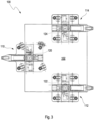
- FIG. 12 shows an arrangement for transporting a load, which is denoted by the reference numeral 100 in its entirety.
- the load is denoted by reference number 102 .
- the arrangement 100 comprises a first rotary heavy-duty undercarriage 110, a second rotary heavy-duty undercarriage 112 and a third rotary heavy-duty undercarriage 114 Figures 1 and 2 formed, so that in this representation the individual components are not described in detail.
- first lifting attachment 120 of the first rotary heavy-duty undercarriage 110, the second lifting attachment 122 of the second rotary heavy-duty undercarriage and the third lifting attachment 124 of the third rotary heavy-duty undercarriage 114 are located under the load 102 so that they are lifted together with the lifting attachments 120, 122, 124 can be. It is advantageous for this if the lifting movements of the lifting mounts 120, 122, 124 take place synchronously with one another.
Landscapes
- Engineering & Computer Science (AREA)
- Structural Engineering (AREA)
- Life Sciences & Earth Sciences (AREA)
- Geology (AREA)
- Mechanical Engineering (AREA)
- Transportation (AREA)
- Civil Engineering (AREA)
- Handcart (AREA)
Description
- Die Erfindung betrifft ein Rotationsschwerlastfahrwerk und eine Anordnung, die mehrere Rotationschwerlastfahrwerke umfasst.
- Schwerlastfahrwerke, insbesondere unbemannte Schwerlastfahrwerke, wie diese bspw. in Logistikzentren oder Werkshallen eingesetzt werden, werden dazu verwendet, schwere Lasten von einem Ort zu einem anderen zu transportieren. Hierzu ist es erforderlich, das Schwerlastfahrwerk oder mehrere Schwerlastfahrwerke zunächst unter die Last zu fahren, dann die Last anzuheben und anschließend die Last zu dem Zielort zu transportieren. Dort angekommen, kann die Last wieder abgesenkt werden und das oder die Schwerlastfahrwerke wieder von der Last entfernt werden. Für den eigentlichen Transport verfügen Schwerlastfahrwerke über Rollen bzw. Räder, die ein Fahren der Schwerlastfahrwerke mit der angehobenen Last ermöglichen. Entsprechend stabil müssen diese Rollen bzw. Räder ausgebildet sein. Sind die Räder bzw. Rollen um eine vertikale Achse drehbar, so spricht man auch von einem Rotationsschwerlastfahrwerk.
- Rotationsschwerlastfahrwerke zum Anheben von Lasten werden vielfältig eingesetzt. Dabei ist es üblicherweise erforderlich, das Rotationsschwerlastfahrwerk oder auch mehrere Rotationsschwerlastfahrwerke unter die Last zu fahren und, sobald diese sich unter der Last befindet bzw. befinden, so zu betätigen, dass die Last angehoben wird, wobei sichergestellt sein sollte, dass die Last sich nicht zu eine Seite hin neigt und die Last somit in der Waagerechten in eine vorab bestimmte Position in vertikaler Richtung angehoben werden kann. Dies stellt insbesondere bei einem unebenen Untergrund oder einem nicht einheitlich beschaffenen Untergrund ein erhebliches Problem dar. Zum Anheben der Last werden sogenannte Hebeaufnahmen verwendet, die in vertikaler Richtung verfahrbar sind, an die Last angreifen und dann diese anheben.
- Die Druckschrift
DE 10 2010 015 115 A1 beschreibt ein mobiles Hebegerät zum Anheben schwerer Lasten mit einem Gestell, einem Hydraulikzylinder und mindestens einer Hydraulikpumpe. Die Hydraulikpumpe ist dabei direkt oder über ein Getriebe von einem Elektromotor angetrieben. Bei schweren Lasten, wie bspw. einer Maschine, kann vorgesehen sein, an den vier Ecken der Maschine vier autarke Hebegeräte anzuordnen, die jeweils über eine eigene Positionsregelung verfügen. - Aus der Druckschrift
DE 10 2009 015 783 U1 ist eine Antriebseinheit für ein Schwerlasttransportsystem bekannt, die eine Tragestruktur, ein Treibrad, das von einem Antriebsmotor angetrieben werden kann, und ein Verbindungsmittel zum Befestigen der Antriebseinheit an einem Transportfahrwerk aufweist. Die Antriebseinheit ist dabei in vertikaler Richtung relativ zu dem Transportfahrwerk angeordnet. Weiterhin sind mehrere Stützräder vorgesehen, die um eine Achse drehbar sind. - Die Druckschrift
DE 10 2013 016 381 A1 beschreibt ein Transportfahrzeug zum störungsfreien Transport von Lastregalen in Werkshallen mit einer Trägerplatte, bei dem ein Neigungssensor zum Einsatz kommt. Antriebsräder sind jeweils an einer Drehachse gesondert gelagert. - Aus der Druckschrift
EP 2 995 584 A1 ist eine Transportvorrichtung für eine Last mit mindestens zwei voneinander beabstandeten Achsen mit jeweils angetriebenen Rädern bekannt. Ein Anheben der Last wird mit Hilfe eines Hydraulikteils bewerkstelligt. Es sind weiterhin Sensoren zum Erfassen einer Umgebung und/oder der Position vorgesehen. - Die Druckschrift
DE 10 2007 046 868 A1 beschreibt eine Transportvorrichtung zum Aufnehmen einer Last, die über Funk steuerbar ist. Zur Überwachung des Betriebs sind Sensoren vorgesehen. - Die Druckschrift
EP 2 886 414 A1 beschreibt eine Transportvorrichtung für Radsätze und Drehgestelle, die wenigstens zwei Transporteinheiten umfasst. Mit einem Sensor wird eine Messgröße erfasst, die proportional zu einer Last ist. Als Sensor kommt bspw. ein Dehnungsmessstreifen in Betracht. - Aus der Druckschrift
EP 2 353 775 A1 ist eine Vorrichtung zum Verschieben eines Gegenstands bekannt. Bei dieser wird ein synchrones Anheben und Absenken des Gegenstands, was mittels einer Hebevorrichtung erfolgt, durch einen Sensor überwacht.DE 10 2016 107451 A1 offenbart den Oberbegriff des Anspruchs 1. - Vor diesem Hintergrund werden ein Rotationsschwerlastfahrwerk mit den Merkmalen des Anspruchs 1 und eine Anordnung nach Anspruch 10 vorgestellt. Ausführungsformen ergeben sich aus den abhängigen Ansprüchen und der Beschreibung.
- Es wird ein Rotationsschwerlastfahrwerk vorgestellt, das eine Tragstruktur bzw. einen Tragerahmen bzw. eine Plattform, mindestens eine Rollenkassette, die um eine vertikale Achse drehbar ist und jeweils mindestens eine Rolle aufweist, wobei die mindestens eine Rollenkassette an einer Unterseite der Tragstruktur angeordnet ist, und mindestens eine Hebeaufnahme zum Durchführen einer Hubbewegung in einer vertikalen Richtung aufweist.
- Die mindestens eine Rollenkassette ist somit derart angeordnet, dass die Rollen über einen Untergrund abrollen können, so dass die Tragstruktur und damit das gesamte Rotationsschwerlastfahrwerk über diesen Untergrund gefahren und damit bewegt werden kann.
- Die Hebeaufnahme ist in bzw. an der Tragstruktur vorgesehen, wobei die mindestens eine Hebeaufnahme dazu eingerichtet ist, an einer Last anzugreifen und diese zu heben. Die Last kann dabei nach oben, d. h. weg vom Untergrund, auf dem sich das Rotationsschwerlastfahrwerk befindet, angehoben werden. Der Hub geht somit in Richtung weg von dem Untergrund nach oben. Hierzu ist der Hebeaufnahme ein Antrieb zugeordnet, der dazu eingerichtet ist, die Hebeaufnahme zum Durchführen einer Hubbewegung anzutreiben.
- Weiterhin ist jeder der mindestens einen Hebeaufnahme ein Wegsensor zugeordnet, der dazu dient, ein Maß der Hubbewegung zu erfassen. Dieser Wegsensor bzw. Wegmesssensor erfasst somit, wie weit die Hebeaufnahme ausgefahren ist.
- Der Antrieb der Hebeaufnahme umfasst bspw. einen Hydraulikzylinder und eine Pumpe. Mit einem Hydraulikzylinder kann der Hub sehr genau eingestellt werden. Die typischerweise elektrische Ansteuerung der Pumpe ermöglicht vielfältige Möglichkeiten zur Steuerung. So kann bspw. über den Druck des Hydraulikzylinders und über die elektrischen Größen zur Ansteuerung der Pumpe der Betrieb genau überwacht werden. Dabei kann bspw. festgestellt werden, ob die Hebeaufnahme bereits an der Last anliegt und zum Anheben dann ein erhöhtes Moment aufgebracht werden muss.
- Es kann weiterhin eine Recheneinheit vorgesehen sein, die ein an dem Hydraulikzylinder anliegenden Druck in einen Gewichtswert umrechnet. Dieser Wert kann dann an eine Anzeige weitergegeben werden, d. h. es wird ein Signal an diese Anzeige weitergegeben, das als Information diesen Wert trägt. Typischerweise wird das Gewicht in kg angegeben. Dieser Wert kann analog oder digital angezeigt werden.
- Die mindestens eine Rolle kann derart angeordnet sein, dass diese einen Nachlauf aufweist. Die Rolle bzw. das Rad läuft dann der Lenkungsdrehachse nach, es dreht sich somit selbst in die gewünschte Fahrtrichtung.
- Die mindestens eine Rolle kann über eine Achsblockierung, bspw. mittels eines Arretierbolzens, blockiert werden. Dies bedeutet, dass bspw. in einer Rollenkassette ein Arretierbolzen durch die Drehachse der Rollen geführt wird, der dann verhindert, dass die Rollen sich weiterhin um eine vertikale Achse drehen können. So kann ein Schwenken der Rollen und damit auch ein Schwenken des gesamten Rotationsschwerlastfahrwerks verhindert werden.
- Es kann bzw. können weiterhin ein Funkempfänger einer Funkanlage und/oder ein Energiespeicher, bspw. eine Batterie oder ein Akkumulator, in dem Rotationsschwerlastfahrwerk integriert sein. Dieses kann dann als autarke Einheit arbeiten.
- Das beschriebene Rotationsschwerlastfahrwerk weist weiterhin einen ausziehbaren Transportgriff auf, mit dem dieses per Hand rangiert werden kann.
- So kann dieses bspw. per Hand unter die anzuhebende Last bewegt werden und anschließend, wenn sich die Last am Zielort befindet, wieder wegbewegt werden.
- Das Rotationsschwerlastfahrwerk kann außerdem über eine abnehmbare Anhängevorrichtung verfügen. So kann, wenn das Rotationsschwerlastfahrwerk mit einer Antriebseinheit bewegt werden soll, eine für diese passende Anhängevorrichtung angebracht werden. Das Rotationsschwerlastfahrwerk ist dann flexibel einsetzbar.
- Die Hebeanordnung kann weiterhin an ihrem oberen Ende einen Drehteller aufweisen, auf dem dann die Last aufliegt.
- Es wird zudem eine Anordnung mit mindestens zwei Rotationsschwerlastfahrwerken der hierin beschriebenen Art vorgestellt, wobei die Rotationsschwerlastfahrwerke über eine gemeinsame Steuerung zu steuern sind. Sobald sich die Rotationsschwerlastfahrwerke unter der Last befinden, können diese dann mit der Steuerung gemeinsam angesteuert werden und die Hebeanordnungen der Rotationsschwerlastfahrwerke können synchron betätigt werden.
- Die Steuerung kann als zentrale Steuerung ausgebildet sein. In diesem Fall kann bspw. auch eines der Rotationsschwerlastfahrwerke als Master dienen, die anderen Rotationsschwerlastfahrwerke sind dann Slaves. Die Rotationsschwerlastfahrwerke können dann über eine Funkverbindung miteinander kommunizieren. Es kann auch eine zentrale externe Steuerung vorgesehen sein, die ebenfalls über eine Funkverbindung mit den Rotationsschwerlastfahrwerken kommunizieren kann.
- Bei einer dezentralen Steuerung übernehmen bspw. die Rotationsschwerlastfahrwerke gemeinsam die Steuerung des Ablaufs.
- Die eingesetzten Wegmesssensoren stellen sicher, dass die Hubbewegungen der Hebeanordnungen aufeinander abgestimmt werden können.
- Es kann weiterhin eine Recheneinheit zum Berechnen eines Gewichts und eine Anzeige zum Anzeigen dieses Gewichts bzw. eines Gewichtswerts vorgesehen sein. Die Recheneinheit kann separat ausgebildet oder in der genannten Steuerung aufgenommen sein.
- Weitere Vorteile und Ausgestaltungen der Erfindung ergeben sich aus der Beschreibung und der beiliegenden Zeichnung.
- Es versteht sich, dass die voranstehend genannten und die nachstehend noch zu erläuternden Merkmale nicht nur in der jeweils angegebenen Kombination, sondern auch in anderen Kombinationen oder in Alleinstellung verwendbar sind, ohne den Rahmen der vorliegenden Erfindung zu verlassen.
-
Figur 1 zeigt in einer Seitenansicht ein Rotationsschwerlastfahrwerk. -
Figur 2 zeigt in einer Draufsicht das Rotationsschwerlastfahrwerk ausFigur 1 . -
Figur 3 zeigt in einer Draufsicht eine Ausführung der vorgestellten Anordnung. - Die Erfindung ist anhand von Ausführungsbeispielen in der Zeichnung schematisch dargestellt und wird im folgenden unter Bezugnahme auf die Zeichnung ausführlich beschrieben.
-
Figur 1 zeigt in einer Seitenansicht eine Ausführung des vorgestellten Rotationsschwerlastfahrwerks, das insgesamt mit der Bezugsziffer 10 bezeichnet ist. Die Darstellung zeigt eine Tragstruktur 12, die eine Grundstruktur darstellt und auch als Plattform oder Tragrahmen bezeichnet werden kann. Diese Tragstruktur ist typischerweise aus einer Struktur aus Rahmenelementen zusammengebaut und bspw. aus einem Metall gefertigt. - Am unteren Ende der Tragstruktur 12 sind eine erste Rolle 14 und eine zweite Rolle 16 angebracht. Weiterhin zeigt die Darstellung eine Anhängevorrichtung 18 und einen ausziehbaren Transportgriff 20.
-
Figur 2 zeigt das Rotationsschwerlastfahrwerk 10 ausFigur 1 in einer Draufsicht. Die Darstellung zeigt die Tragstruktur 12, eine erste Rollenkassette 24 mit drei ersten Rollen 14, eine zweite Rollenkassette 26 mit drei zweiten Rollen 16, eine dritte Rollenkassette 28 mit drei dritten Rollen 30 und eine vierte Rollenkassette 32 mit drei vierten Rollen 34. Die Rollenkassetten 24, 26, 28 und 32 sind jeweils um eine vertikale Drehachse 40, 42, 44 bzw. 46 drehbar. Die Rollen 14, 16, 30 und 34 verfügen bezogen auf ihre Drehachse 40, 42, 44 bzw. 46 jeweils über einen Nachlauf. - Weiterhin zeigt
Figur 2 die Anhängevorrichtung 18, die abnehmbar ist, so dass das Rotationsschwerlastfahrwerk 10 von unterschiedlichen Fahrzeugen mit verschiedenen Kupplungen gezogen werden kann. An der Anhängevorrichtung 18 sind eine Ladebuchse 50, ein Schalter 52 und eine Kontrollleuchte 54 vorgesehen. - Die Darstellung zeigt weiterhin einen Akku 60 als Energiespeicher, der über die Ladebuchse 50 zu laden ist, die ausziehbaren Transportgriffe 20, einen Funkempfänger 62 einer Fernsteuerung, in der auch ein Wegmesssensor 63 als Weg- bzw. Hubmesssystem integriert ist, eine Hebeanordnung bzw. -aufnahme 64, auf der ein Drehteller 66, der wiederum über eine Arretierung verfügt, angeordnet ist, eine Pumpe 68 bzw. Hydraulikpumpe, einen Hydraulikzylinder 70 und zwei Arretierbolzen 72 zum Arretieren der zweiten und vierten Rollen 16 und 34, so dass diese nicht mehr um ihre Drehachse 42 bzw. 46 gedreht bzw. geschwenkt werden können.
- Die Darstellung verdeutlicht, dass alle Komponenten, die zum Betrieb erforderlich sind, in dem Rotationsschwerlastfahrwerk integriert sind. Auf diese Weise ist ein autarker Betrieb des Rotationsschwerlastfahrwerks möglich.
-
Figur 3 zeigt eine Anordnung zum Transportieren einer Last, die insgesamt mit der Bezugsziffer 100 bezeichnet ist. Die Last ist mit Bezugsziffer 102 bezeichnet. - Die Anordnung 100 umfasst ein erstes Rotationsschwerlastfahrwerk 110, ein zweites Rotationsschwerlastfahrwerk 112 und ein drittes Rotationsschwerlastfahrwerk 114. Diese Rotationsschwerlastfahrwerke 110, 112, 114 sind entsprechend dem Rotationsschwerlastfahrwerk 10 aus
Figuren 1 und 2 ausgebildet, so dass in dieser Darstellung die einzelnen Komponenten nicht näher bezeichnet werden. - Von Bedeutung ist, dass die erste Hebeaufnahme 120 des ersten Rotationsschwerlastfahrwerks 110, die zweite Hebeaufnahme 122 des zweiten Rotationsschwerlastfahrwerks und die dritte Hebeaufnahme 124 des dritten Rotationsschwerlastfahrwerks 114 sich so unter der Last 102 befinden, dass diese mit den Hebeaufnahmen 120, 122, 124 zusammen angehoben werden kann. Hierfür ist von Vorteil, wenn die Hubbewegungen der Hebeaufnahmen 120, 122, 124 zueinander synchron erfolgen.
Claims (11)
- Rotationsschwerlastfahrwerk mit- einer Tragstruktur (12),- mindestens einer Rollenkassette (24, 26, 28, 32), die um eine vertikale Achse drehbar ist und jeweils mindestens eine Rolle (14, 16, 30, 34) aufweist, wobei die mindestens eine Rollenkassette (24, 26, 28, 32) an einer Unterseite der Tragstruktur (12) angeordnet ist,- mindestens einer Hebeaufnahme (64, 120, 122, 124) zum Durchführen einer Hubbewegung in einer vertikalen Richtung, die in der Tragstruktur (12) vorgesehen ist, wobei die mindestens eine Hebeaufnahme (64, 120, 122, 124) dazu eingerichtet ist, an einer Last (102) anzugreifen und diese zu heben, und wobei der Hebeaufnahme (64, 120, 122, 124) ein Antrieb zugeordnet ist, der dazu eingerichtet ist, die Hebeaufnahme (64, 120, 122, 124) zum Durchführen einer Hubbewegung anzutreiben, wobeijeder der mindestens einen Hebeaufnahme (64, 120, 122, 124) ein Wegsensor 63 zugeordnet ist, der dazu dient, ein Maß der Hubbewegung zu erfassen,dadurch gekennzeichnet, dassdas Rotationsschwerlastfahrwerk (10, 110, 112, 114) über einen ausziehbaren Transportgriff (20) verfügt.
- Rotationsschwerlastfahrwerk nach Anspruch 1, bei dem der Antrieb der Hebeaufnahme (64, 120, 122, 124) einen Hydraulikzylinder (70) und eine Pumpe (68) umfasst.
- Rotationsschwerlastfahrwerk nach Anspruch 2, bei dem eine Recheneinheit vorgesehen ist, die dazu eingerichtet ist, einen Druck, der an dem Hydraulikzylinder (70) anliegt, in ein Gewicht umzurechnen und den berechneten Wert für das Gewicht an eine Anzeige zum Anzeigen dieses Werts weiterzugeben.
- Rotationsschwerlastfahrwerk nach einem der Ansprüche 1 bis 3, bei dem die mindestens eine Rolle (14, 16, 30, 34) derart angeordnet ist, dass diese einen Nachlauf aufweist.
- Rotationsschwerlastfahrwerk nach einem der Ansprüche 1 bis 4, bei dem die mindestens eine Rolle (14, 16, 30, 34) über eine Achsblockierung zu blockieren ist.
- Rotationsschwerlastfahrwerk nach einem der Ansprüche 1 bis 5, in dem ein Funkempfänger (62) einer Funkanlage integriert ist.
- Rotationsschwerlastfahrwerk nach einem der Ansprüche 1 bis 6, in dem ein Energiespeicher integriert ist.
- Rotationsschwerlastfahrwerk nach einem der Ansprüche 1 bis 7, das über eine abnehmbare Anhängervorrichtung (18) verfügt.
- Anordnung mit mindestens zwei Rotationsschwerlastfahrwerken (10, 110, 112, 114) nach einem der Ansprüche 1 bis 9, wobei die Rotationsschwerlastfahrwerke (10, 110, 112, 114) über eine gemeinsame Steuerung zu steuern sind.
- Anordnung nach Anspruch 9, die eine zentrale Steuerung aufweist.
- Anordnung nach Anspruch 9 oder 10, die eine Recheneinheit zum Umrechnen eines Drucks in ein Gewicht und eine Anzeige zum Anzeigen eines Werts für das Gewicht aufweist.
Applications Claiming Priority (1)
| Application Number | Priority Date | Filing Date | Title |
|---|---|---|---|
| DE202019101761.9U DE202019101761U1 (de) | 2019-03-28 | 2019-03-28 | Rotationsschwerlastfahrwerk |
Publications (2)
| Publication Number | Publication Date |
|---|---|
| EP3718950A1 EP3718950A1 (de) | 2020-10-07 |
| EP3718950B1 true EP3718950B1 (de) | 2023-04-12 |
Family
ID=66548563
Family Applications (1)
| Application Number | Title | Priority Date | Filing Date |
|---|---|---|---|
| EP19217804.4A Active EP3718950B1 (de) | 2019-03-28 | 2019-12-19 | Rotationsschwerlastfahrwerk |
Country Status (2)
| Country | Link |
|---|---|
| EP (1) | EP3718950B1 (de) |
| DE (1) | DE202019101761U1 (de) |
Families Citing this family (1)
| Publication number | Priority date | Publication date | Assignee | Title |
|---|---|---|---|---|
| DE202022101564U1 (de) | 2022-03-24 | 2022-06-09 | Udo Idler | Schwerlastfahrzeug |
Family Cites Families (12)
| Publication number | Priority date | Publication date | Assignee | Title |
|---|---|---|---|---|
| ITRM20010646A1 (it) * | 2001-11-02 | 2003-05-02 | Roberto Maggiori | Dispositivo di sollevamento integrato auto livellante. |
| DE102007046868B9 (de) | 2007-09-28 | 2023-08-31 | Universität Stuttgart | Transportvorrichtung für Ladungsträger und Verfahren zu deren Steuerung |
| DE102009015783A1 (de) | 2009-03-31 | 2010-10-14 | Siemens Aktiengesellschaft | Neurologisches Sequenzprotokoll |
| DE202010001761U1 (de) | 2010-02-03 | 2010-07-08 | Hering, Michael | Vorrichtung zum Verschieben eines Gegenstandes |
| DE102010015115A1 (de) | 2010-04-16 | 2011-10-20 | Georg Kramp Gmbh & Co. Kg | Mobiles Hebegerät mit elektro-hydraulischem Antrieb |
| DE102013009386A1 (de) * | 2013-06-01 | 2014-12-04 | Jungheinrich Aktiengesellschaft | Routenzuganhänger mit einer Hubeinrichtung |
| DE102013016381A1 (de) | 2013-09-30 | 2015-04-02 | Grenzebach Maschinenbau Gmbh | Transportfahrzeug und Verfahren zum störungsfreien Transport von Lastregalen in Werkshallen mit Funkabschattungen und mit teilweise autonomem Fahrbetrieb |
| DE102013017062A1 (de) * | 2013-10-15 | 2015-04-16 | Eisenmann Ag | Fördereinheit und Fördersystem zum Fördern von Ladungsträgern |
| EP2886414B1 (de) | 2013-12-20 | 2019-05-08 | Schweizerische Bundesbahnen SBB | Transportvorrichtung für Radsätze und Drehgestelle |
| DE202014000755U1 (de) * | 2014-01-30 | 2015-05-04 | Hit Hafen- Und Industrietechnik Gmbh | Schwerlastniederflurfahrzeug, und System mit einem oder mehreren dieser Fahrzeuge |
| DE102014106033A1 (de) | 2014-04-29 | 2015-10-29 | Pester Pac Automation Gmbh | Transportvorrichtung und Verwendung |
| DE102016107451A1 (de) * | 2015-04-21 | 2016-10-27 | Gesellschaft Für Ingenieurdienste Mbh | Selbstfahrende Transport- und Hubfahreinheit und Verfahren zum Bewegen von Objekten mittels der Transport- und Hubfahreinheit |
-
2019
- 2019-03-28 DE DE202019101761.9U patent/DE202019101761U1/de not_active Expired - Lifetime
- 2019-12-19 EP EP19217804.4A patent/EP3718950B1/de active Active
Also Published As
| Publication number | Publication date |
|---|---|
| DE202019101761U1 (de) | 2019-04-29 |
| EP3718950A1 (de) | 2020-10-07 |
Similar Documents
| Publication | Publication Date | Title |
|---|---|---|
| EP2794345B1 (de) | Lastkraftwagen mit einem mehrachsigen fahrgestell zum transportieren, absetzen und aufnehmen von stückgut | |
| DE102017220580A1 (de) | Transportsystem zum automatisierten Transportieren eines Fahrzeugs mit mindestens einem Transportroboter | |
| WO2013182448A2 (de) | Crawler zum transport von lasten und ein system sowie ein verfahren zum transport von lasten | |
| DE102007015356A1 (de) | Bestimmung der Masse eines Flugzeugs | |
| EP3815956A1 (de) | Fahrerlose transportvorrichtung und fahrerloses transportsystem zum transportieren von gegenständen | |
| EP3426545A1 (de) | Antriebseinheit und antriebsverfahren | |
| EP2070864B1 (de) | Verfahren zum Betrieb eines Flurförderzeugs | |
| DE102016220810A1 (de) | Proaktives Verringern von Schwingungen in einem Flurförderzeug | |
| EP2593333A1 (de) | Fahrzeug in modularer bauweise | |
| EP3718950B1 (de) | Rotationsschwerlastfahrwerk | |
| EP3816600B1 (de) | Fahrerlose transportvorrichtung und fahrerloses transportsystem zum transportieren von gegenständen sowie verfahren zum betreiben einer fahrerlosen transportvorrichtung und eines fahrerlosen transportsystems zum transportieren von gegenständen | |
| WO2020109549A1 (de) | Fahrerloses transportfahrzeug sowie verfahren zum koppeln eines fahrerlosen transportfahrzeugs mit einem sattelauflieger | |
| EP3816752B1 (de) | Fahrerloses transportsystem zum transportieren von gegenständen sowie verfahren zum betreiben eines fahrerlosen transportsystems zum transportieren von gegenständen | |
| WO2021083628A1 (de) | Fahrerlose transportvorrichtung und fahrerloses transportsystem zum transportieren von gegenständen sowie verfahren zum betreiben einer fahrerlosen transportvorrichtung und eines fahrerlosen transportsystems zum transportieren von gegenständen | |
| DE102010050930B4 (de) | Mobile Hebebühne sowie Verfahren zur Überwachung eines Fahrwerks der mobilen Hebebühne | |
| EP3848324B1 (de) | Fahrerloses transportfahrzeug | |
| EP2560859B1 (de) | Bewegbares system | |
| WO2014179897A1 (de) | Elastisch deformierbarer lastträger mit einer messanordnung für die last | |
| EP3815852B1 (de) | Fahrerlose transportvorrichtung und fahrerloses transportsystem zum transportieren von gegenständen | |
| EP0983899B1 (de) | Ladevorrichtung zum Be- und Entladen eines Fahrzeuges | |
| DE202017101795U1 (de) | Erfassungseinrichtung und Stabilisierungseinrichtung | |
| DE19850902C2 (de) | Schnellmontagebaugruppe für einen Turmdrehkran | |
| EP3848325B1 (de) | Fahrerloses transportfahrzeug mit hilfsabstützvorrichtung | |
| DE202022102790U1 (de) | Ermittlungsmodul, Rangiersystem und Anhänger | |
| DE102007060433A1 (de) | Verfahren zum Betrieb eines Flurförderzeugs |
Legal Events
| Date | Code | Title | Description |
|---|---|---|---|
| PUAI | Public reference made under article 153(3) epc to a published international application that has entered the european phase |
Free format text: ORIGINAL CODE: 0009012 |
|
| STAA | Information on the status of an ep patent application or granted ep patent |
Free format text: STATUS: THE APPLICATION HAS BEEN PUBLISHED |
|
| AK | Designated contracting states |
Kind code of ref document: A1 Designated state(s): AL AT BE BG CH CY CZ DE DK EE ES FI FR GB GR HR HU IE IS IT LI LT LU LV MC MK MT NL NO PL PT RO RS SE SI SK SM TR |
|
| AX | Request for extension of the european patent |
Extension state: BA ME |
|
| STAA | Information on the status of an ep patent application or granted ep patent |
Free format text: STATUS: REQUEST FOR EXAMINATION WAS MADE |
|
| 17P | Request for examination filed |
Effective date: 20210406 |
|
| RBV | Designated contracting states (corrected) |
Designated state(s): AL AT BE BG CH CY CZ DE DK EE ES FI FR GB GR HR HU IE IS IT LI LT LU LV MC MK MT NL NO PL PT RO RS SE SI SK SM TR |
|
| GRAP | Despatch of communication of intention to grant a patent |
Free format text: ORIGINAL CODE: EPIDOSNIGR1 |
|
| STAA | Information on the status of an ep patent application or granted ep patent |
Free format text: STATUS: GRANT OF PATENT IS INTENDED |
|
| INTG | Intention to grant announced |
Effective date: 20221130 |
|
| GRAS | Grant fee paid |
Free format text: ORIGINAL CODE: EPIDOSNIGR3 |
|
| GRAA | (expected) grant |
Free format text: ORIGINAL CODE: 0009210 |
|
| STAA | Information on the status of an ep patent application or granted ep patent |
Free format text: STATUS: THE PATENT HAS BEEN GRANTED |
|
| AK | Designated contracting states |
Kind code of ref document: B1 Designated state(s): AL AT BE BG CH CY CZ DE DK EE ES FI FR GB GR HR HU IE IS IT LI LT LU LV MC MK MT NL NO PL PT RO RS SE SI SK SM TR |
|
| REG | Reference to a national code |
Ref country code: GB Ref legal event code: FG4D Free format text: NOT ENGLISH |
|
| REG | Reference to a national code |
Ref country code: CH Ref legal event code: EP |
|
| REG | Reference to a national code |
Ref country code: DE Ref legal event code: R096 Ref document number: 502019007436 Country of ref document: DE |
|
| REG | Reference to a national code |
Ref country code: IE Ref legal event code: FG4D Free format text: LANGUAGE OF EP DOCUMENT: GERMAN |
|
| REG | Reference to a national code |
Ref country code: AT Ref legal event code: REF Ref document number: 1559685 Country of ref document: AT Kind code of ref document: T Effective date: 20230515 |
|
| REG | Reference to a national code |
Ref country code: LT Ref legal event code: MG9D |
|
| REG | Reference to a national code |
Ref country code: NL Ref legal event code: MP Effective date: 20230412 |
|
| PG25 | Lapsed in a contracting state [announced via postgrant information from national office to epo] |
Ref country code: NL Free format text: LAPSE BECAUSE OF FAILURE TO SUBMIT A TRANSLATION OF THE DESCRIPTION OR TO PAY THE FEE WITHIN THE PRESCRIBED TIME-LIMIT Effective date: 20230412 |
|
| PG25 | Lapsed in a contracting state [announced via postgrant information from national office to epo] |
Ref country code: SE Free format text: LAPSE BECAUSE OF FAILURE TO SUBMIT A TRANSLATION OF THE DESCRIPTION OR TO PAY THE FEE WITHIN THE PRESCRIBED TIME-LIMIT Effective date: 20230412 Ref country code: PT Free format text: LAPSE BECAUSE OF FAILURE TO SUBMIT A TRANSLATION OF THE DESCRIPTION OR TO PAY THE FEE WITHIN THE PRESCRIBED TIME-LIMIT Effective date: 20230814 Ref country code: NO Free format text: LAPSE BECAUSE OF FAILURE TO SUBMIT A TRANSLATION OF THE DESCRIPTION OR TO PAY THE FEE WITHIN THE PRESCRIBED TIME-LIMIT Effective date: 20230712 Ref country code: ES Free format text: LAPSE BECAUSE OF FAILURE TO SUBMIT A TRANSLATION OF THE DESCRIPTION OR TO PAY THE FEE WITHIN THE PRESCRIBED TIME-LIMIT Effective date: 20230412 |
|
| PG25 | Lapsed in a contracting state [announced via postgrant information from national office to epo] |
Ref country code: RS Free format text: LAPSE BECAUSE OF FAILURE TO SUBMIT A TRANSLATION OF THE DESCRIPTION OR TO PAY THE FEE WITHIN THE PRESCRIBED TIME-LIMIT Effective date: 20230412 Ref country code: PL Free format text: LAPSE BECAUSE OF FAILURE TO SUBMIT A TRANSLATION OF THE DESCRIPTION OR TO PAY THE FEE WITHIN THE PRESCRIBED TIME-LIMIT Effective date: 20230412 Ref country code: LV Free format text: LAPSE BECAUSE OF FAILURE TO SUBMIT A TRANSLATION OF THE DESCRIPTION OR TO PAY THE FEE WITHIN THE PRESCRIBED TIME-LIMIT Effective date: 20230412 Ref country code: LT Free format text: LAPSE BECAUSE OF FAILURE TO SUBMIT A TRANSLATION OF THE DESCRIPTION OR TO PAY THE FEE WITHIN THE PRESCRIBED TIME-LIMIT Effective date: 20230412 Ref country code: IS Free format text: LAPSE BECAUSE OF FAILURE TO SUBMIT A TRANSLATION OF THE DESCRIPTION OR TO PAY THE FEE WITHIN THE PRESCRIBED TIME-LIMIT Effective date: 20230812 Ref country code: HR Free format text: LAPSE BECAUSE OF FAILURE TO SUBMIT A TRANSLATION OF THE DESCRIPTION OR TO PAY THE FEE WITHIN THE PRESCRIBED TIME-LIMIT Effective date: 20230412 Ref country code: GR Free format text: LAPSE BECAUSE OF FAILURE TO SUBMIT A TRANSLATION OF THE DESCRIPTION OR TO PAY THE FEE WITHIN THE PRESCRIBED TIME-LIMIT Effective date: 20230713 Ref country code: AL Free format text: LAPSE BECAUSE OF FAILURE TO SUBMIT A TRANSLATION OF THE DESCRIPTION OR TO PAY THE FEE WITHIN THE PRESCRIBED TIME-LIMIT Effective date: 20230412 |
|
| PG25 | Lapsed in a contracting state [announced via postgrant information from national office to epo] |
Ref country code: FI Free format text: LAPSE BECAUSE OF FAILURE TO SUBMIT A TRANSLATION OF THE DESCRIPTION OR TO PAY THE FEE WITHIN THE PRESCRIBED TIME-LIMIT Effective date: 20230412 |
|
| REG | Reference to a national code |
Ref country code: DE Ref legal event code: R097 Ref document number: 502019007436 Country of ref document: DE |
|
| PG25 | Lapsed in a contracting state [announced via postgrant information from national office to epo] |
Ref country code: SK Free format text: LAPSE BECAUSE OF FAILURE TO SUBMIT A TRANSLATION OF THE DESCRIPTION OR TO PAY THE FEE WITHIN THE PRESCRIBED TIME-LIMIT Effective date: 20230412 |
|
| PG25 | Lapsed in a contracting state [announced via postgrant information from national office to epo] |
Ref country code: SM Free format text: LAPSE BECAUSE OF FAILURE TO SUBMIT A TRANSLATION OF THE DESCRIPTION OR TO PAY THE FEE WITHIN THE PRESCRIBED TIME-LIMIT Effective date: 20230412 Ref country code: SK Free format text: LAPSE BECAUSE OF FAILURE TO SUBMIT A TRANSLATION OF THE DESCRIPTION OR TO PAY THE FEE WITHIN THE PRESCRIBED TIME-LIMIT Effective date: 20230412 Ref country code: RO Free format text: LAPSE BECAUSE OF FAILURE TO SUBMIT A TRANSLATION OF THE DESCRIPTION OR TO PAY THE FEE WITHIN THE PRESCRIBED TIME-LIMIT Effective date: 20230412 Ref country code: EE Free format text: LAPSE BECAUSE OF FAILURE TO SUBMIT A TRANSLATION OF THE DESCRIPTION OR TO PAY THE FEE WITHIN THE PRESCRIBED TIME-LIMIT Effective date: 20230412 Ref country code: DK Free format text: LAPSE BECAUSE OF FAILURE TO SUBMIT A TRANSLATION OF THE DESCRIPTION OR TO PAY THE FEE WITHIN THE PRESCRIBED TIME-LIMIT Effective date: 20230412 Ref country code: CZ Free format text: LAPSE BECAUSE OF FAILURE TO SUBMIT A TRANSLATION OF THE DESCRIPTION OR TO PAY THE FEE WITHIN THE PRESCRIBED TIME-LIMIT Effective date: 20230412 |
|
| PLBE | No opposition filed within time limit |
Free format text: ORIGINAL CODE: 0009261 |
|
| STAA | Information on the status of an ep patent application or granted ep patent |
Free format text: STATUS: NO OPPOSITION FILED WITHIN TIME LIMIT |
|
| 26N | No opposition filed |
Effective date: 20240115 |
|
| PGFP | Annual fee paid to national office [announced via postgrant information from national office to epo] |
Ref country code: DE Payment date: 20240119 Year of fee payment: 5 |
|
| PG25 | Lapsed in a contracting state [announced via postgrant information from national office to epo] |
Ref country code: SI Free format text: LAPSE BECAUSE OF FAILURE TO SUBMIT A TRANSLATION OF THE DESCRIPTION OR TO PAY THE FEE WITHIN THE PRESCRIBED TIME-LIMIT Effective date: 20230412 |
|
| PG25 | Lapsed in a contracting state [announced via postgrant information from national office to epo] |
Ref country code: SI Free format text: LAPSE BECAUSE OF FAILURE TO SUBMIT A TRANSLATION OF THE DESCRIPTION OR TO PAY THE FEE WITHIN THE PRESCRIBED TIME-LIMIT Effective date: 20230412 Ref country code: IT Free format text: LAPSE BECAUSE OF FAILURE TO SUBMIT A TRANSLATION OF THE DESCRIPTION OR TO PAY THE FEE WITHIN THE PRESCRIBED TIME-LIMIT Effective date: 20230412 |
|
| REG | Reference to a national code |
Ref country code: CH Ref legal event code: PL |
|
| PG25 | Lapsed in a contracting state [announced via postgrant information from national office to epo] |
Ref country code: LU Free format text: LAPSE BECAUSE OF NON-PAYMENT OF DUE FEES Effective date: 20231219 |
|
| PG25 | Lapsed in a contracting state [announced via postgrant information from national office to epo] |
Ref country code: MC Free format text: LAPSE BECAUSE OF FAILURE TO SUBMIT A TRANSLATION OF THE DESCRIPTION OR TO PAY THE FEE WITHIN THE PRESCRIBED TIME-LIMIT Effective date: 20230412 |
|
| GBPC | Gb: european patent ceased through non-payment of renewal fee |
Effective date: 20231219 |
|
| REG | Reference to a national code |
Ref country code: BE Ref legal event code: MM Effective date: 20231231 |
|
| PG25 | Lapsed in a contracting state [announced via postgrant information from national office to epo] |
Ref country code: MC Free format text: LAPSE BECAUSE OF FAILURE TO SUBMIT A TRANSLATION OF THE DESCRIPTION OR TO PAY THE FEE WITHIN THE PRESCRIBED TIME-LIMIT Effective date: 20230412 Ref country code: LU Free format text: LAPSE BECAUSE OF NON-PAYMENT OF DUE FEES Effective date: 20231219 |
|
| REG | Reference to a national code |
Ref country code: IE Ref legal event code: MM4A |
|
| PG25 | Lapsed in a contracting state [announced via postgrant information from national office to epo] |
Ref country code: IE Free format text: LAPSE BECAUSE OF NON-PAYMENT OF DUE FEES Effective date: 20231219 |
|
| PG25 | Lapsed in a contracting state [announced via postgrant information from national office to epo] |
Ref country code: GB Free format text: LAPSE BECAUSE OF NON-PAYMENT OF DUE FEES Effective date: 20231219 |
|
| PG25 | Lapsed in a contracting state [announced via postgrant information from national office to epo] |
Ref country code: BE Free format text: LAPSE BECAUSE OF NON-PAYMENT OF DUE FEES Effective date: 20231231 |
|
| PG25 | Lapsed in a contracting state [announced via postgrant information from national office to epo] |
Ref country code: FR Free format text: LAPSE BECAUSE OF NON-PAYMENT OF DUE FEES Effective date: 20231231 |
|
| PG25 | Lapsed in a contracting state [announced via postgrant information from national office to epo] |
Ref country code: CH Free format text: LAPSE BECAUSE OF NON-PAYMENT OF DUE FEES Effective date: 20231231 |
|
| PG25 | Lapsed in a contracting state [announced via postgrant information from national office to epo] |
Ref country code: IE Free format text: LAPSE BECAUSE OF NON-PAYMENT OF DUE FEES Effective date: 20231219 Ref country code: GB Free format text: LAPSE BECAUSE OF NON-PAYMENT OF DUE FEES Effective date: 20231219 Ref country code: FR Free format text: LAPSE BECAUSE OF NON-PAYMENT OF DUE FEES Effective date: 20231231 Ref country code: CH Free format text: LAPSE BECAUSE OF NON-PAYMENT OF DUE FEES Effective date: 20231231 Ref country code: BE Free format text: LAPSE BECAUSE OF NON-PAYMENT OF DUE FEES Effective date: 20231231 |
|
| PG25 | Lapsed in a contracting state [announced via postgrant information from national office to epo] |
Ref country code: BG Free format text: LAPSE BECAUSE OF FAILURE TO SUBMIT A TRANSLATION OF THE DESCRIPTION OR TO PAY THE FEE WITHIN THE PRESCRIBED TIME-LIMIT Effective date: 20230412 |
|
| PG25 | Lapsed in a contracting state [announced via postgrant information from national office to epo] |
Ref country code: BG Free format text: LAPSE BECAUSE OF FAILURE TO SUBMIT A TRANSLATION OF THE DESCRIPTION OR TO PAY THE FEE WITHIN THE PRESCRIBED TIME-LIMIT Effective date: 20230412 |
|
| REG | Reference to a national code |
Ref country code: DE Ref legal event code: R119 Ref document number: 502019007436 Country of ref document: DE |
|
| PG25 | Lapsed in a contracting state [announced via postgrant information from national office to epo] |
Ref country code: CY Free format text: LAPSE BECAUSE OF FAILURE TO SUBMIT A TRANSLATION OF THE DESCRIPTION OR TO PAY THE FEE WITHIN THE PRESCRIBED TIME-LIMIT; INVALID AB INITIO Effective date: 20191219 |
|
| PG25 | Lapsed in a contracting state [announced via postgrant information from national office to epo] |
Ref country code: HU Free format text: LAPSE BECAUSE OF FAILURE TO SUBMIT A TRANSLATION OF THE DESCRIPTION OR TO PAY THE FEE WITHIN THE PRESCRIBED TIME-LIMIT; INVALID AB INITIO Effective date: 20191219 |
|
| PG25 | Lapsed in a contracting state [announced via postgrant information from national office to epo] |
Ref country code: DE Free format text: LAPSE BECAUSE OF NON-PAYMENT OF DUE FEES Effective date: 20250701 |
|
| PG25 | Lapsed in a contracting state [announced via postgrant information from national office to epo] |
Ref country code: TR Free format text: LAPSE BECAUSE OF FAILURE TO SUBMIT A TRANSLATION OF THE DESCRIPTION OR TO PAY THE FEE WITHIN THE PRESCRIBED TIME-LIMIT Effective date: 20230412 |
|
| REG | Reference to a national code |
Ref country code: AT Ref legal event code: MM01 Ref document number: 1559685 Country of ref document: AT Kind code of ref document: T Effective date: 20241219 |
|
| PG25 | Lapsed in a contracting state [announced via postgrant information from national office to epo] |
Ref country code: AT Free format text: LAPSE BECAUSE OF NON-PAYMENT OF DUE FEES Effective date: 20241219 |
|
| PGFP | Annual fee paid to national office [announced via postgrant information from national office to epo] |
Ref country code: AT Payment date: 20260410 Year of fee payment: 5 |