EP3719212B1 - Système de remappage d'un signal de contrôle des mouvements de bras d'excavateur à un degré de liberté rotatif d'un outil - Google Patents
Système de remappage d'un signal de contrôle des mouvements de bras d'excavateur à un degré de liberté rotatif d'un outil Download PDFInfo
- Publication number
- EP3719212B1 EP3719212B1 EP19166908.4A EP19166908A EP3719212B1 EP 3719212 B1 EP3719212 B1 EP 3719212B1 EP 19166908 A EP19166908 A EP 19166908A EP 3719212 B1 EP3719212 B1 EP 3719212B1
- Authority
- EP
- European Patent Office
- Prior art keywords
- tool
- freedom
- axis
- movement
- degrees
- Prior art date
- Legal status (The legal status is an assumption and is not a legal conclusion. Google has not performed a legal analysis and makes no representation as to the accuracy of the status listed.)
- Active
Links
Images


Classifications
-
- E—FIXED CONSTRUCTIONS
- E02—HYDRAULIC ENGINEERING; FOUNDATIONS; SOIL SHIFTING
- E02F—DREDGING; SOIL-SHIFTING
- E02F9/00—Component parts of dredgers or soil-shifting machines, not restricted to one of the kinds covered by groups E02F3/00 - E02F7/00
- E02F9/20—Drives; Control devices
- E02F9/2004—Control mechanisms, e.g. control levers
- E02F9/2012—Setting the functions of the control levers, e.g. changing assigned functions among operations levers, setting functions dependent on the operator or seat orientation
-
- E—FIXED CONSTRUCTIONS
- E02—HYDRAULIC ENGINEERING; FOUNDATIONS; SOIL SHIFTING
- E02F—DREDGING; SOIL-SHIFTING
- E02F9/00—Component parts of dredgers or soil-shifting machines, not restricted to one of the kinds covered by groups E02F3/00 - E02F7/00
- E02F9/20—Drives; Control devices
- E02F9/2025—Particular purposes of control systems not otherwise provided for
- E02F9/2037—Coordinating the movements of the implement and of the frame
-
- E—FIXED CONSTRUCTIONS
- E02—HYDRAULIC ENGINEERING; FOUNDATIONS; SOIL SHIFTING
- E02F—DREDGING; SOIL-SHIFTING
- E02F3/00—Dredgers; Soil-shifting machines
- E02F3/04—Dredgers; Soil-shifting machines mechanically-driven
- E02F3/28—Dredgers; Soil-shifting machines mechanically-driven with digging tools mounted on a dipper- or bucket-arm, i.e. there is either one arm or a pair of arms, e.g. dippers, buckets
- E02F3/36—Component parts
- E02F3/42—Drives for dippers, buckets, dipper-arms or bucket-arms
- E02F3/43—Control of dipper or bucket position; Control of sequence of drive operations
- E02F3/435—Control of dipper or bucket position; Control of sequence of drive operations for dipper-arms, backhoes or the like
- E02F3/439—Automatic repositioning of the implement, e.g. automatic dumping, auto-return
-
- E—FIXED CONSTRUCTIONS
- E02—HYDRAULIC ENGINEERING; FOUNDATIONS; SOIL SHIFTING
- E02F—DREDGING; SOIL-SHIFTING
- E02F9/00—Component parts of dredgers or soil-shifting machines, not restricted to one of the kinds covered by groups E02F3/00 - E02F7/00
- E02F9/26—Indicating devices
- E02F9/264—Sensors and their calibration for indicating the position of the work tool
- E02F9/265—Sensors and their calibration for indicating the position of the work tool with follow-up actions (e.g. control signals sent to actuate the work tool)
-
- G—PHYSICS
- G05—CONTROLLING; REGULATING
- G05B—CONTROL OR REGULATING SYSTEMS IN GENERAL; FUNCTIONAL ELEMENTS OF SUCH SYSTEMS; MONITORING OR TESTING ARRANGEMENTS FOR SUCH SYSTEMS OR ELEMENTS
- G05B19/00—Program-control systems
- G05B19/02—Program-control systems electric
- G05B19/18—Numerical control [NC], i.e. automatically operating machines, in particular machine tools, e.g. in a manufacturing environment, so as to execute positioning, movement or co-ordinated operations by means of program data in numerical form
-
- E—FIXED CONSTRUCTIONS
- E02—HYDRAULIC ENGINEERING; FOUNDATIONS; SOIL SHIFTING
- E02F—DREDGING; SOIL-SHIFTING
- E02F3/00—Dredgers; Soil-shifting machines
- E02F3/04—Dredgers; Soil-shifting machines mechanically-driven
- E02F3/28—Dredgers; Soil-shifting machines mechanically-driven with digging tools mounted on a dipper- or bucket-arm, i.e. there is either one arm or a pair of arms, e.g. dippers, buckets
- E02F3/36—Component parts
- E02F3/3604—Devices to connect tools to arms, booms or the like
- E02F3/3677—Devices to connect tools to arms, booms or the like allowing movement, e.g. rotation or translation, of the tool around or along another axis as the movement implied by the boom or arms, e.g. for tilting buckets
- E02F3/3681—Rotators
-
- G—PHYSICS
- G05—CONTROLLING; REGULATING
- G05B—CONTROL OR REGULATING SYSTEMS IN GENERAL; FUNCTIONAL ELEMENTS OF SUCH SYSTEMS; MONITORING OR TESTING ARRANGEMENTS FOR SUCH SYSTEMS OR ELEMENTS
- G05B19/00—Program-control systems
- G05B19/02—Program-control systems electric
- G05B19/04—Program control other than numerical control, i.e. in sequence controllers or logic controllers
- G05B19/10—Program control other than numerical control, i.e. in sequence controllers or logic controllers using selector switches
- G05B19/106—Program control other than numerical control, i.e. in sequence controllers or logic controllers using selector switches for selecting a program, variable or parameter
Definitions
- the present invention relates to a system for controlling movement of multiple links of an excavator in order to move a tool arranged at the end of an excavator arm, wherein an operator of the excavator can directly adjust the position and particularly the orientation of the tool relative to a reference surface, without needing to coordinate underlying joint movements.
- Excavators are construction machinery comprising a boom, a stick (also called dipper), a tool, e.g. a bucket, and a cab (also called house) on a rotating platform.
- the cab is typically rotatable about 360 degrees and arranged on a movable undercarriage having tracks or wheels, wherein the boom and the stick form a movable excavator arm carrying the tool.
- These machines are used in many ways, e.g. for digging, landscaping, material handling, brush cutting, e.g. with hydraulic saw and mower attachments, forestry work, demolition, e.g. with hydraulic claw, cutter, and breaker attachments, mining, driving piles, in conjunction with a pile driver, drilling, e.g. using an auger or hydraulic drill attachment, and snow removal, e.g. with snowplow and snow blower attachments.
- movement and functions of the excavator may be accomplished through the use of hydraulic cylinders and hydraulic motors.
- hydraulic excavators come in a wide variety of sizes.
- cable-operated excavators use winches and steel ropes to accomplish the movements.
- Typical excavators share a basic setup, wherein the section of the excavator arm closest to the cab is referred to as the (main) boom, while the section which carries the tool is referred to as the stick (also referred to as the dipper or the dipper-stick).
- the (main) boom attaches to the cab, and can be one of several different configurations, e.g. a mono boom allowing no movement apart from straight up and down, or a knuckle boom articulating at the so-called "knuckle" near the middle, letting it fold back like a finger.
- a hinge at the base of the boom allowing it to pivot independent to the house, e.g. up to 180 degrees.
- the latter is generally available only to compact excavators.
- somewhat specialized configurations are known, e.g. triple-articulated booms.
- the stick length varies, e.g. depending whether reach (longer stick) or break-out power (shorter stick) is required.
- the stick length may also be hydraulically adjustable.
- the tool is attached on the end of the stick, e.g. the tool being a bucket coming in a variety of sizes and shapes.
- a wide, large capacity (mud) bucket with a straight cutting edge is used for cleanup and levelling.
- a straight cutting edge is typically used for soft material to be dug, wherein for harder material the cutting edge is formed by a row of teeth.
- a general purpose bucket is generally smaller, stronger, and has hardened side cutters and teeth used to break through hard ground and rocks.
- the tool is attached to the stick via a tool joint allowing at least a swiveling of the tool with respect to the stick in a pitch direction, typically up and down. Often also a swiveling in a tilt direction is possible, e.g. left and right.
- a special excavator type further features a so-called tilt-rotator arrangement (also referred to as “tilt-rotator”) between the end of the stick and the tool in order to increase the flexibility and precision of the excavator.
- tilt-rotator excavators are often used in the countries of Scandinavia.
- a tilt-rotator can best be described as a wrist between the stick and the tool, allowing the tool to rotate - typically by 360 degrees - about a rotor axis, wherein the tool can further be swiveled, e.g. in each case up to ⁇ 45 degrees, about a pitch axis perpendicular to the rotor axis, and a tilt axis perpendicular to the rotor axis and the pitch axis.
- prior art support and remapping functionalities typically cause a situation-dependent interruption between a normal operation, i.e. a manual control of individual cylinder or joint movements, and the aided automatic operation.
- a normal operation i.e. a manual control of individual cylinder or joint movements
- a high-level of skill is required to assess a current situation at the end of or during an automated movement, i.e. the impact of the current excavator arm and tool position on the tool movement commanded by the normal operation of the manual controls. Therefore, even for an expert operator it is difficult to seamlessly take over manual control of the tool movement at the end of the aided functionality or during the aided functionality, e.g. to make on-the-fly adjustments.
- the invention relates to a system for controlling movement of multiple links of an excavator in order to move a tool arranged at the end of an excavator arm, particularly wherein the tool is attached to a tilt-rotator arrangement.
- the system comprises an input interface configured to receive input signals carrying user commands for moving at least part of the multiple links with respect to each other about corresponding joints, and an output interface configured to provide output signals for multiple actuators controlling the movement of the multiple links.
- the input signals are provided by various excavator user-input devices, e.g. two x-y joysticks and particularly further buttons and/or rollers, wherein each controller movement and/or activation is mapped to a cylinder or joint movement in order to control different movements of the cab, the boom, the stick, and the tool with respect to one another.
- the output signal may be a control signal for a hydraulic cylinder.
- the system further comprises a sensor data interface configured to receive sensor data for determining, particularly in real-time, relative orientations of the multiple links with respect to each other, e.g. wherein the sensor data provide a current setting of a joint associated with two successive links, more specifically velocity information for an angular and/or translational movement of the two consecutive links about their associated joint.
- sensor information can be provided. Different types of sensors can be used, e.g. angular or linear encoders, accelerometers, gyroscopes, laser sensors, ultrasound sensors, etc.
- the sensor data may also include position information for determining the position of the excavator with respect to a reference in the environment and/or for determining the position of a target point on one of the multiple links with respect to the reference in the environment.
- the sensor data may include data of a laser-ranging device and/or coordinate measuring device, e.g. data of a total station or a laser tracker determining, and particularly tracking, the position of a target point on one of the multiple links, e.g. wherein the target point is represented by a cooperative target such as a retroreflective prism or a target ball.
- the sensor data may include absolute position information for determining an absolute position of the excavator or one of the multiple links with respect to an earth coordinate system, e.g. based on a global navigation satellite system.
- the system comprises a surface setting unit configured to be provided with (to have access to) design data, e.g. computer aided design data, defining a reference surface, wherein the surface setting unit has input means to provide a setting functionality for setting the reference surface.
- design data e.g. computer aided design data
- the system may be configured that the setting functionality comprises a selection functionality with a plurality of predefined options for the setting of the reference surface.
- Different reference surfaces may already be stored on a storage unit of the system or a user may provide design data defining all or additional reference surfaces to be used for a certain working task.
- the surface setting unit may also have access to a remote server unit with a database of available design data for different reference surfaces.
- the system comprises a remapping unit configured to remap a user command for moving two of the multiple links with respect to each other about a corresponding joint to an associated rotatory tool degree of freedom out of three independent rotatory tool degrees of freedom of a movement of the tool with respect to the reference surface.
- the remapping unit is configured to coordinate the output signals based on the sensor data, the design data, and an inverse kinematics algorithm, such that as a function of the remapped user command the tool is rotated within the associated rotatory tool degree of freedom.
- the tool in response to the initial user command for a single joint movement, the tool is rotated within the associated rotatory tool degree of freedom based on automatically generated output signals providing a coordinated joint movement.
- these output signals are typically configured that an orientation of the tool with respect to the other two rotatory tool degrees of freedom is unaffected.
- the system allows an operator to directly adjust the orientation and position of the tool relative to the reference surface, without needing to coordinate the individual underlying joint and cylinder movements.
- it allows an intuitive interplay between manual and automatic control of the excavator elements.
- the system allows a seamless division of responsibilities between a manual user and an automatic control system, wherein the automatic control system can adjust certain movements relative to the reference surface, and an operator can adjust others, without interfering with each other's task.
- precision tasks can be easily performed by a non-expert operator.
- a precision task may require digging in straight lines, wherein for a correctly defined reference surface for this task, the user inputs will directly result in the required straight-line digging.
- the inventive system facilitates the use of a tilt or tilt-rotator articulation.
- These articulations significantly expand the capabilities of an excavator, but at the cost of increased operating complexity. This is one of the reasons why these articulations are only commonly used in some parts of the world.
- the inventive system it is straightforward for an operator who is not used to a tilt or tilt-rotator arrangement to benefit from it without significant training.
- Inverse Kinematics In the field of robotics, algorithms for calculating joint movements required to cause a desired tool movement are called Inverse Kinematics. Such algorithms are based on a set of mathematical relations that describe the relationship between the excavator links, e.g. based on geometrical machine data such as link lengths, joint degrees of freedom, actuator placements, and movement restrictions of individual joints. There are several different general approaches for achieving this, and the invention is not limited to any particular approach.
- the remapping unit comprises a model of a particular excavator type, i.e. an algorithm implemented as software on a computer to calculate the individual joint movements required to achieve a particular angular and/or linear movement of the tool relative to the reference surface.
- the system may be configured to process data from an inertial measurement unit comprising accelerometers and gyroscopes, wherein the system is configured to determine relative orientations of the multiple links with respect to each other by a fusion of the data from the accelerometers and the gyroscopes using a state estimation algorithm, particularly a Kalman filter.
- a state estimation algorithm particularly a Kalman filter.
- the remapping unit is configured to remap the user command and to coordinate the output signals based on design data providing the reference surface as one of a plane having a slope defined relative to the gravity vector, wherein the plane is fixed with respect to the ground; a plane having a slope defined relative to the gravity vector, wherein the position of the plane is fixed with respect to a cab swing axis defining a rotation of the cab of the excavator, i.e.
- the plane position is independent from a rotation of the cab around the cab swing axis but it displaces with the body of the excavator; a plane having a slope defined relative to the gravity vector, wherein the position of the plane is fixed to an orientation of the cab of the excavator around a cab swing axis defining a rotation of the cab, i.e. wherein the plane displaces with the body of the excavator and also rotates with the rotation of the cab; and a surface defined by a 3D model in a geodetic coordinate system.
- the plane may have any slope, e.g. zero slope (so-called horizontal plane) or a slope defined by a particular work plan.
- a dedicated surface may be defined for a particular working step, e.g. wherein a dedicated surface such as a plane defining a driveway shape is set based on a 3D model, e.g. a CAD model of the worksite.
- the system may be configured that an operator can set the slope of the plane.
- the rotatory tool degree of freedom may be defined based on a tool coordinate frame with orthogonal axes that is fixed to the tool.
- the rotatory tool degrees of freedom are rotations based on three basic rotations about three orthogonal axes, wherein each basic rotation causes a change in a different component of the axis-angle rotation vector, resolved in the tool coordinate frame, relating the reference coordinate frame to the tool coordinate frame.
- the rotatory tool degrees of freedom can be described as any combination of the angles in a sequence of three rotations (Euler angles) relating a coordinate frame fixed to the reference surface to the tool coordinate frame.
- the system is configured to move a tool having an attack edge (also called blade or blade edge) dedicated for contacting a surface, e.g. a bucket having a blade embodied as a continuous cutting edge or embodied by individual blade elements (teeth) arranged next to each other, and the three independent rotatory tool degrees of freedom are: a rotation to set an attack angle of the attack edge, a rotation to set a crosscut angle of the attack edge, and a rotation to set a heading angle of the attack edge.
- a tool having an attack edge also called blade or blade edge
- the three independent rotatory tool degrees of freedom are: a rotation to set an attack angle of the attack edge, a rotation to set a crosscut angle of the attack edge, and a rotation to set a heading angle of the attack edge.
- the attack angle, the crosscut angle, and the heading angle are of particular importance when using an excavator with a tilt-rotator arrangement.
- the attack angle and the crosscut angles are defined with respect to an orthogonal X, Y, Z coordinate frame that is fixed to the tool, wherein the X axis is parallel to an attack direction of the attack edge, e.g. the digging direction / cutting direction of the blade, and the Y axis is parallel to the attack edge.
- the attack angle is defined as the angle between the X axis and the reference surface
- the crosscut angle is defined as the angle between the Y axis and the reference surface
- the heading angle is defined as the angle of rotation about a normal to the reference surface.
- the remapping unit is configured to remap at least a further user command for a movement of the multiple links with respect to each other onto one of the three independent rotatory tool degrees of freedom, wherein the above mentioned remapped user command and the remapped further user command are remapped onto the attack angle and the crosscut angle, respectively.
- the system has a presetting unit configured to provide for a setting of a target parameter defining the tool orientation within the associated rotatory tool degree of freedom, particularly a target angle and/or a tolerance range for a movement of the tool with respect to the associated rotary tool degree of freedom, and the system is configured to coordinate the output signals such that the tool is oriented based on the target parameter.
- a target parameter defining the tool orientation within the associated rotatory tool degree of freedom, particularly a target angle and/or a tolerance range for a movement of the tool with respect to the associated rotary tool degree of freedom
- the system is configured to coordinate the output signals such that the tool is oriented based on the target parameter.
- an operator may manually provide, e.g. over a touch screen, an attack angle of the blade which is then set and automatically maintained by the system.
- the orientation of the tool within the three independent rotatory tool degrees of freedom is settable by a movement of a part of the multiple links about corresponding tool orientation joints.
- the tool orientation joints may comprise a so-called bucket joint providing "opening/closing" the bucket, a so-called tilt joint providing "left/right” tilting of the bucket, and a so-called roto joint providing rotation of the bucket.
- the bucket is rotatable about a rotor axis defined by the roto joint, swiveled about a pitch axis (defined by the bucket joint) perpendicular to the rotor axis, and swiveled about a tilt axis (defined by the tilt joint) perpendicular to the rotor axis and the pitch axis.
- the bucket joint, tilt joint, and roto joint are not moved in case non-remapped user inputs are used, e.g. when the boom, stick, or yaw are moved.
- the rotatory tool degrees of freedom are unaffected by non-remapped user commands and the rotatory tool degrees of freedom do not change.
- the bucket joint, tilt joint and roto joint will move together in a coordinated way to ensure that the attack angle changes at the desired rate, typically without any change in the crosscut angle or the heading angle.
- the remapping unit is configured to coordinate the output signals based on a non-remapped user command addressing a movement of two of the multiple links about a corresponding joint which is different from the tool orientation joints, and the remapping unit is configured to coordinate the output signals such that a current orientation of the part of the multiple links about the corresponding tool orientation joints is unaffected by the non-remapped user command.
- the system may also be configured that an enablement state for automatic readjustment of a rotary tool degree of freedom is selectable by a user.
- the automatically readjusted degrees of freedom are regulated to remain at a preset target value or within a target range by using a feedback control loop. This means that deviations from the target value or range are detected and automatically eliminated by initiating corrective movement. These deviations could be caused by, for example, the movement of other parts of the machine, and/or by movement of the reference surface.
- a particular user input command addressing a particular automatically adjusted degree of freedom may be allowed to cause a change in the corresponding rotary tool degree of freedom without elimination by the feedback control system.
- the remapping unit has an automatic readjustment functionality configured to coordinate the output signals such that in the absence of the user command for moving the two of the multiple links the movement of the part of the multiple links which sets the orientation of the tool within the three independent rotatory tool degrees of freedom about the corresponding tool orientation joints is automatically controlled such that a current orientation of the tool with respect to the associated rotatory tool degree of freedom is automatically maintained.
- system has an automatic stop functionality configured to coordinate the output signals such that a crossing of the reference surface by a point of reference on the tool is automatically prevented.
- some user commands may also be mapped directly to linear degrees of freedom of the tool. Similar to the rotatory degrees of freedom, these linear degrees of freedom are also defined relative to the reference surface and may also be automatically controlled by the system.
- the remapping unit is configured to remap a user command which is not remapped onto one of the three independent rotatory tool degrees of freedom onto an associated linear tool degree of freedom out of three independent linear tool degrees of freedom of a movement of the tool with respect to the reference surface, wherein the remapping unit is further configured to coordinate the output signals such that as a function of the user command remapped onto the linear tool degree of freedom the tool is moved within the associated linear tool degree of freedom.
- the three independent linear tool degrees of freedom are a movement of the tool along an axis Z" orthogonal to the reference surface, a movement of the tool along an axis X" parallel to the reference surface, and a movement of the tool along an axis Y" parallel to the reference surface, the axis Y" being orthogonal to the axis X''.
- the three independent linear tool degrees of freedom are a vertical movement of the tool along the gravity vector, a movement of the tool along an axis X" in the horizontal plane, and a movement of the tool along an axis Y" in the horizontal plane, the axis Y" being perpendicular to the axis X".
- one embodiment of the invention relates to a system for controlling movement of multiple links of an excavator, wherein the excavator comprises: a cab, which is rotatable about a cab swing axis; a boom, which is attached to the cab and can be swiveled with respect to the cab about a boom joint defining a boom axis; a stick, which is attached to the boom and can be swiveled with respect to the boom about a stick joint defining a stick axis; a tilt-rotator arrangement which is attached at the end of the stick; and the tool, which is attached to the tilt-rotator arrangement, wherein the tilt-rotator arrangement is configured that the tool can be rotated about a rotor axis, swiveled about a pitch axis perpendicular to the rotor axis, and swiveled about a tilt axis perpendicular to the rotor axis and the pitch axis.
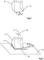
- Figure 1 exemplarily shows the basic components of an excavator, i.e. the cab 1, the boom 2, the stick 3, and the tool 4.
- the excavator is embodied as hydraulic excavator.
- the (main) boom 2 is the arm element closest to the cab 1. It attaches to the cab 1 via a boom joint, which can be one of several configurations.
- the boom 2 is configured as a mono boom, wherein the boom joint allows no movement apart from swiveling up and down about a boom axis 5.
- the cab 1 is arranged on an undercarriage 6, here having tracks, and is rotatable with respect to the undercarriage 6 about 360 degrees about a cab joint defining a cab axis 7.
- the stick 3 is attached to the boom via a stick joint so that it can be swiveled about a stick axis 8.
- the tool 4 is attached at the far end of the stick 3, so that it can be swiveled at least about a tool joint defining a pitch axis 9.
- the excavator further comprises a so-called tilt-rotator arrangement 10 providing a swiveling of the tool 4 about a tilt axis 11 and a 360 degree rotation of the tool 4 about a rotor axis 12.
- tilt-rotator arrangement 10 provides an increased flexibility and precision of the excavator.
- operating an excavator arm having a tilt-rotator arrangement 10 quickly and precisely is a highly skilled task, as the excavator operator needs to constantly assess the impact of the current excavator arm and tool position on the tool movement when coordinating all the individual joint movements.
- the Excavator links and joints can vary and there are many different excavator types available, e.g. with dual booms, yaw-able booms, extendible sticks, etc.
- the invention can be applied to all these different machine types.
- Figures 2 and 3 show an exemplary definition of three independent rotatory tool degrees of freedom for the movement of the tool 4 relative to a reference surface 13, e.g. an inclined plane.
- the remapping of the user command is based on a tool coordinate frame with three orthogonal axes X, Y, Z that is fixed to the tool as depicted by Fig. 2 , and a reference coordinate frame with three orthogonal axes X', Y', Z' that is fixed to the reference surface 13 as depicted by Fig. 3 .
- the tool 4 is a bucket, which has a continuous blade edge 14, wherein the X axis is parallel to the digging direction of the blade edge 14, and the Y axis is parallel to the blade edge 14.
- three rotatory tool degrees of freedom relative to the reference surface 13 are then defined: a rotation about the axis that is parallel to the reference surface and perpendicular to X, which causes the angle between the X axis and the reference surface to change, which is also referred to as the attack angle 15; a rotation about the axis that is parallel to the reference surface and perpendicular to Y, which causes the angle between the Y axis and the reference surface to change, which is also referred to as the crosscut angle 16; and a rotation about the normal 17 to the reference surface about a so-called heading angle 18, which causes a change in the heading of the tool 4 relative to the reference surface 13.
- Figure 4 shows an exemplary definition of three independent linear tool degrees of freedom for the movement of the tool 4 relative to the reference surface 13.
- the three linear tool degrees of freedom are defined as: movement of the tool 4 along an axis Z" orthogonal to the reference surface 13; movement of the tool 4 along an axis X" parallel to the reference surface 13; and movement of the tool 4 along an axis Y" parallel to the reference surface 13, the axis Y" being orthogonal to the axis X".
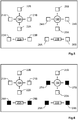
- Figures 5 to 9 exemplarily show different remapping schemes for controlling an excavator having a tilt-rotator arrangement, wherein some hand-operated user inputs - by means of two joysticks 19A,19B and two rollers 20A,20B - are remapped from their standard mapping directly to angular and/or linear degrees of freedom (so-called controlled DOFs) of the tool defined relative to an (imaginary) reference surface.
- controlled DOFs degrees of freedom
- the system uses: a calculation unit, e.g. a computer, electronic logic circuit, or microcontroller; an interface to allow reception of the user inputs, e.g. from pressure sensors if the joysticks are hydraulic; sensors that serve to deduce some or all of the joint angles of the excavator arm, e.g. tilt sensors, rotary sensors, and linear sensors; a mathematical kinematic model of the excavator arm used by a software running on the computing unit; and an interface to allow computer-control of some of the excavator joint movements, e.g. a hydraulic interface for converting electrical signals into hydraulic flow or pressure.
- a calculation unit e.g. a computer, electronic logic circuit, or microcontroller
- an interface to allow reception of the user inputs, e.g. from pressure sensors if the joysticks are hydraulic
- sensors that serve to deduce some or all of the joint angles of the excavator arm e.g. tilt sensors, rotary sensors, and linear sensors
- Figure 5 shows an exemplary mapping scheme for normal operation, i.e. wherein all the individual joint movements are manually coordinated.
- left/right movement of the left joystick 19A is addressing the cab joint for left 21A and right 21B swing of the excavator arm (rotating the cab 1 around the cab axis 7, see Fig. 1 ), and back/forth movement of the left joystick 19A is addressing the stick joint for extending 22A and retracting 22B the stick cylinder, i.e. for swiveling the stick 3 around the stick axis 8.
- the left roller 20A is used for anti-clockwise 23A and clockwise 23B rotation of the tool around the rotor joint, i.e. for rotating the tool 4 around the rotor axis 12.
- Left/right movement of the right joystick 19B is addressing the tool joint for extending 24A and retracting 24B the tool cylinder, i.e. swiveling the tool 4 around the pitch axis 9, and back and forth movement of the right joystick 19B is addressing the boom joint for extending 25A and retracting 25B the boom cylinder, i.e. for swiveling the boom 2 around the boom axis 5.
- the right roller 20B is used for anti-clockwise 26A and clockwise 26B swiveling of the tool 4 around the tilt axis 11.
- Figure 6 shows an exemplary remapping for the two joysticks and the two rollers of Fig. 5 onto three rotatory degrees of freedom according to one embodiment of the invention.
- the left/right inputs 24A,24B ( Fig. 5 ) of the right joystick 19B used for swiveling the tool 4 around the pitch axis 9 are remapped onto an increase 27A and decrease 27B of the attack angle 15 (see Fig. 3 ) of the tool 4 with respect to the reference surface 13.
- the inputs 23A,23B of the left roller 20A are remapped to a rotation about the normal 17 to the reference surface 13, i.e. an anti-clockwise 28A and clockwise 28B change of the heading angle 18 of the tool (4) relative to the reference surface 13.
- the inputs 26A,26B of the right roller 20B are remapped onto an increase 29A and decrease 29B of the crosscut angle 16 of the tool 4 with respect to the reference surface 13.
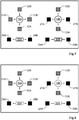
- Figure 7 shows an embodiment, wherein the angular remapping of Fig. 6 is further extended by also remapping controller commands of Fig. 5 onto three linear degrees of freedom.
- the left/right inputs 21A,21B ( Fig. 5 ) of the left joystick 19A used for left/right swing of the excavator arm are remapped onto a linear left 31A and a linear right 31B movement of the tool 4 along the axis Y" parallel to the reference surface 13 according to Fig. 4 .
- the back/forth movements 22A,22B of the left joystick 19A used for extending/retracting the stick cylinder are remapped onto a linear moving out 32A and a linear moving back 32B of the tool 4 along the axis X" parallel to the reference surface 13 according to Fig. 4 .
- Figure 8 shows another embodiment of the angular/linear remapping scheme according to Fig. 7 , wherein some degrees of freedom are automatically controlled such that previously set values are automatically kept fixed or kept within a certain threshold range, i.e. the operator is not required to use/control the corresponding controls anymore.
- the input commands associated with the right joystick 19B and with the two rollers 20A,20B are automatically controlled, i.e. the three rotatory degrees of freedom - attack angle 15, crosscut angle 16, and heading angle 18 - as well as the distance of the tool 4 to the reference surface 13.
- the system may be configured that after each input by the right joystick 19B or the two rollers 20A,20B the set value is controlled as long as the respective controls are not used anymore.
- the system may be configured for being provided with a target parameter defining a specific setting of the automatically controlled degrees of freedom of the tool, e.g. wherein an operator can manually provide an attack angle (15) over a touch screen, which is then automatically set and maintained by the system.
- system is further configured that an enablement state for the automatic control is selectable by a user.
- the definition of the reference surface may change during operation in response to user input, e.g. by selecting options with buttons or on a touch screen.
- the remapping system could be activated, e.g. the remapping could be permanently active or it could only be activated on request, e.g. at the push of a button.
- left/right movement of the left joystick 19A may correspond to normal operation, e.g.
- back/forth movements 22A,22B of the left joystick 19A may be remapped onto linear moving out/back 32A,32B of the tool 4 along the axis X
- left/right inputs 24A,24B of the right joystick 19B may be remapped onto an increase/decrease 27A,27B of the attack angle 15
- the inputs 23A,23B of the left roller 20A may be remapped to a change of the heading angle
- the back/forth movements 25A,25B of the right joystick 19B may be remapped onto linear decrease/increase 33A,33B of the distance of the tool 4 to the reference surface 13 along the normal Z
- the inputs 26A,26B of the right roller 20B may be remapped onto an increase/decrease 29A,29B of the crosscut angle 16, wherein the input commands associated with the right roller 20B and the back/forth movements of the right joystick 19B are automatically controlled.
- Figure 9 shows a system block diagram, wherein the remapping algorithm 40 is fed by movement input 41 for controlling movement of the excavator, e.g. command signals by means of a joystick. Furthermore, the remapping algorithm 40 is provided with design data 42 defining a reference surface, e.g. based on a 3D model, as well as with raw or processed sensor data 43 describing a current state of the excavator.
- the sensor data 43 may comprise joint angles, joint rates, linear and/or rotary encoder signals, inclinometer sensor signals, gyroscope sensor signals, laser-ranging data, coordinate measuring data, GNSS receiver signals, etc.
- a user may provide the remapping algorithm 40 with further user options 44, e.g. a selection of automatically controlled DOFs and/or a selection of target parameters such as target values or movement ranges for automatically controlled DOFs.
- further user options 44 e.g. a selection of automatically controlled DOFs and/or a selection of target parameters such as target values or movement ranges for automatically controlled DOFs.
- the remapping algorithm 40 then makes use of a kinematic model 45 of the excavator type to calculate the individual joint movements required to achieve a particular movement of the tool relative to the reference surface. Based on this, the remapping algorithm 40 provides actuator commands 46 configured to control movement of the excavator links, e.g. control signals comprising actuator positions and actuator velocities, hydraulic command pressures, hydraulic command flows, and electrical currents or voltages.
- actuator commands 46 configured to control movement of the excavator links, e.g. control signals comprising actuator positions and actuator velocities, hydraulic command pressures, hydraulic command flows, and electrical currents or voltages.
- the remapping algorithm 40 may be implemented as follows: At each discrete time instant, given the current position of the excavator arm, the sensitivity of the controlled rotatory and linear degree of freedom of the tool with respect to the reference surface are calculated, i.e. those degrees of freedom that are mapped to user controls, e.g. caused by joystick movements. Thereby, the rotatory and linear degree of freedom are represented by the vectors p ang and p lin , respectively, with respect to the vector of joint angles ⁇ .
- the calculation of the J matrix is straightforward for a person skilled in robotics.
- the above equation is a system of linear equations. It relates the changes in the controlled DOFs to both the directly manually actuated joint movements and the remapped joint movements. It can be solved for the remapped joint movements using standard methods.
Landscapes
- Engineering & Computer Science (AREA)
- Mining & Mineral Resources (AREA)
- Civil Engineering (AREA)
- General Engineering & Computer Science (AREA)
- Structural Engineering (AREA)
- Mechanical Engineering (AREA)
- Human Computer Interaction (AREA)
- Manufacturing & Machinery (AREA)
- Physics & Mathematics (AREA)
- General Physics & Mathematics (AREA)
- Automation & Control Theory (AREA)
- Operation Control Of Excavators (AREA)
Claims (15)
- Système pour commander le mouvement de multiples liaisons (1, 2, 3, 10) d'une excavatrice pour déplacer un outil (4) disposé à l'extrémité d'un bras d'excavatrice, en particulier dans lequel l'outil (4) est fixé à un agencement de tiltrotateur (10), le système comprenant :• une interface d'entrée configurée pour recevoir des signaux d'entrée (41) portant des ordres d'utilisateur (21A - 26B) pour déplacer au moins une partie des multiples liaisons (1, 2, 3, 10) les unes par rapport aux autres autour d'articulations correspondantes et• une interface de sortie configurée pour fournir des signaux de sortie (46) pour de multiples actionneurs commandant le déplacement des multiples liaisons (1, 2, 3, 10),caractérisé en ce que
le système comprend :• une interface de données de capteur configurée pour recevoir des données de capteur (43) pour déterminer, en particulier en temps réel, des orientations relatives des multiples liaisons (1, 2, 3, 10) les unes par rapport aux autres,• une unité de définition de surface configurée pour recevoir des données de conception (42) définissant une surface de référence (13), l'unité de définition de surface ayant des moyens d'entrée pour fournir une fonctionnalité de définition pour définir la surface de référence (13), et• une unité de remappage configurée :o pour remapper (27A - 29B) un ordre d'utilisateur (21A - 26B) pour déplacer deux des multiples liaisons (1, 2, 3, 10) l'une par rapport à l'autre autour d'une articulation correspondante à un degré de liberté d'outil rotatif associé (15, 16, 18) parmi trois degrés de liberté d'outil rotatif indépendants (15, 16, 18) d'un déplacement de l'outil (4) par rapport à la surface de référence (13) eto pour coordonner les signaux de sortie (46) sur la base des données de capteur (43), des données de conception (42) et d'un algorithme de cinématique inverse (45), de sorte qu'en fonction de l'ordre d'utilisateur remappé (21A - 26B), l'outil (4) est tourné à l'intérieur du degré de liberté d'outil rotatif associé (15, 16, 18). - Système selon la revendication 1,
caractérisé en ce que
le système est configuré pour déplacer un outil (4) ayant un bord d'attaque (14) destiné à entrer en contact avec une surface, dans lequel les trois degrés de liberté d'outil rotatif indépendants (15, 16, 18) sont :• une rotation pour définir un angle d'attaque (15) du bord d'attaque (14),• une rotation pour définir un angle de coupe en travers (16) du bord d'attaque (14) et• une rotation pour définir un angle de cap (18) du bord d'attaque (14). - Système selon la revendication 2,
caractérisé en ce que
l'axe X est parallèle à une direction d'attaque du bord d'attaque (14) et l'axe Y est parallèle au bord d'attaque (14), dans lequel• l'angle d'attaque (15) est défini comme l'angle entre l'axe X et la surface de référence (13),• l'angle de coupe en travers (16) est défini comme l'angle entre l'axe Y et la surface de référence (13) et• l'angle de cap (18) est défini comme l'angle de rotation autour d'une normale à la surface de référence (13). - Système selon la revendication 2 ou 3,
caractérisé en ce que
l'unité de remappage est configurée pour remapper (27A - 29B) au moins un ordre d'utilisateur supplémentaire (21A - 26B) pour un déplacement des multiples liaisons (1, 2, 3, 10) les unes par rapport aux autres sur l'un des trois degrés de liberté d'outil rotatif indépendants, dans lequel l'ordre d'utilisateur remappé (21A - 26B) et l'ordre d'utilisateur supplémentaire remappé (21A - 26B) sont remappés respectivement sur l'angle d'attaque (15) et l'angle de coupe en travers (16). - Système selon l'une quelconque des revendications précédentes,
caractérisé en ce que• le système comporte une unité de prédéfinition configurée pour fournir une définition d'un paramètre cible définissant l'orientation de l'outil à l'intérieur du degré de liberté d'outil rotatif associé (15, 16, 18), en particulier un angle cible et/ou une plage de tolérance pour un déplacement de l'outil (4) par rapport au degré de liberté d'outil rotatif associé (15, 16, 18), et• le système est configuré pour coordonner les signaux de sortie de telle sorte que l'outil (4) soit orienté sur la base du paramètre cible. - Système selon l'une quelconque des revendications précédentes,
caractérisé en ce que
l'orientation de l'outil (4) à l'intérieur des trois degrés de liberté d'outil rotatif indépendants (15, 16, 18) est réglable par un déplacement d'une partie des multiples liaisons autour d'articulations d'orientation d'outil correspondantes, dans lequel• l'unité de remappage est configurée pour coordonner les signaux de sortie sur la base d'un ordre d'utilisateur non remappé concernant un déplacement de deux des multiples liaisons autour d'une articulation correspondante qui est différente des articulations d'orientation d'outil et• l'unité de remappage est configurée pour coordonner les signaux de sortie de telle sorte qu'une orientation actuelle de la partie des multiples liaisons autour des articulations d'orientation d'outil correspondantes ne soit pas affectée par l'ordre d'utilisateur non remappé. - Système selon l'une des revendications 1 à 5,
caractérisé en ce que
l'orientation de l'outil (4) à l'intérieur des trois degrés de liberté d'outil rotatif indépendants (15, 16, 18) peut être définie par un déplacement d'une partie des multiples liaisons autour d'articulations d'orientation d'outil correspondantes, dans lequel l'unité de remappage a une fonctionnalité de réajustement automatique configurée pour coordonner les signaux de sortie de telle sorte qu'en l'absence de l'ordre d'utilisateur pour déplacer les deux des multiples liaisons (1, 2, 3, 10), le déplacement de la partie des multiples liaisons autour des articulations d'orientation d'outil correspondantes est automatiquement commandé de telle sorte qu'une orientation actuelle de l'outil par rapport au degré de liberté d'outil rotatif associé (15, 16, 18) soit automatiquement maintenue. - Système selon l'une quelconque des revendications précédentes,
caractérisé en ce que
le système a une fonctionnalité d'arrêt automatique configurée pour coordonner les signaux de sortie de telle sorte qu'un franchissement de la surface de référence (13) par un point de référence sur l'outil soit automatiquement empêché. - Système selon l'une quelconque des revendications précédentes,
caractérisé en ce que
l'unité de remappage est configurée pour remapper (27A - 29B) l'ordre d'utilisateur (21A - 26B) et pour coordonner les signaux de sortie (46) sur la base de données de conception (42) fournissant la surface de référence (13) comme l'un des éléments parmi :• un plan ayant une pente définie par rapport au vecteur gravité, dans lequel le plan est fixe par rapport au sol,• un plan ayant une pente définie par rapport au vecteur gravité, dans lequel la position du plan est fixe par rapport à un axe de pivotement de cabine (7) définissant une rotation de la cabine de l'excavatrice,• un plan ayant une pente définie par rapport au vecteur gravité, dans lequel la position du plan est fixe par rapport à une orientation de la cabine de l'excavatrice autour d'un axe de pivotement de cabine (7) définissant une rotation de la cabine et• une surface définie par un modèle 3D dans un système de coordonnées géodésiques. - Système selon l'une quelconque des revendications précédentes,
caractérisé en ce que
la fonctionnalité de définition comprend une fonctionnalité de sélection avec une pluralité d'options prédéfinies pour la définition de la surface de référence (13). - Système selon l'une quelconque des revendications précédentes,
caractérisé en ce que
l'unité de remappage est configurée :• pour remapper (31A - 33B) un ordre d'utilisateur (21A - 26B) qui n'est pas remappé sur l'un des trois degrés de liberté d'outil rotatif indépendants (15, 16, 18) sur un degré de liberté d'outil linéaire associé parmi trois degrés de liberté d'outil linéaire indépendants d'un déplacement de l'outil (4) par rapport à la surface de référence (13) et• pour coordonner les signaux de sortie de telle sorte qu'en fonction de l'ordre d'utilisateur remappé sur le degré de liberté d'outil linéaire, l'outil est déplacé à l'intérieur du degré de liberté d'outil linéaire associé. - Système selon la revendication 11,
caractérisé en ce que
les trois degrés de liberté d'outil linéaire indépendants sont :• un déplacement de l'outil (4) le long d'un axe Z" orthogonal à la surface de référence (13),• un déplacement de l'outil (4) le long d'un axe X" parallèle à la surface de référence (13) et• un déplacement de l'outil (4) le long d'un axe Y" parallèle à la surface de référence (13), l'axe Y" étant orthogonal à l'axe X". - Système selon la revendication 11,
caractérisé en ce que
les trois degrés de liberté d'outil linéaire indépendants sont :• un déplacement vertical de l'outil (4) le long du vecteur gravité,• un déplacement de l'outil (4) le long d'un axe X" dans le plan horizontal et• un déplacement de l'outil (4) le long d'un axe Y" dans le plan horizontal, l'axe Y" étant perpendiculaire à l'axe X". - Système selon l'une quelconque des revendications précédentes,
caractérisé en ce que
l'excavatrice comprend :• une cabine (1) qui peut tourner autour d'un axe de pivotement de cabine (7),• une flèche (2) qui est fixée à la cabine (1) et peut pivoter par rapport à la cabine (1) autour d'une articulation de flèche définissant un axe de flèche (5),• un bras (3) qui est fixé à la flèche (2) et peut pivoter par rapport à la flèche (2) autour d'une articulation de bras définissant un axe de bras (8),• un agencement de tiltrotateur (10) qui est fixé à l'extrémité du bras (3) et• l'outil (4) qui est fixé à l'agencement de tiltrotateur (10), dans lequel l'agencement de tiltrotateur (10) est configuré de telle sorte que l'outil (4) peut tourner autour d'un axe de rotor (12), pivoter autour d'un axe de tangage (9) perpendiculaire à l'axe de rotor (12) et pivoter autour d'un axe d'inclinaison (11) perpendiculaire à l'axe de rotor (12) et à l'axe de tangage (9),dans lequel l'unité de remappage est configurée pour remapper• l'ordre d'utilisateur (25A, 25B) pour faire pivoter la flèche (2) autour de l'axe de flèche (5) sur un premier des trois degrés de liberté d'outil linéaire indépendants,• l'ordre d'utilisateur (22A, 22B) pour faire pivoter le bras (3) autour de l'axe de bras (8) sur un deuxième des trois degrés de liberté d'outil linéaire indépendants, dans lequel le deuxième degré de liberté d'outil linéaire est différent du premier degré de liberté d'outil linéaire,• l'ordre d'utilisateur (21A, 21B) pour faire tourner la cabine (1) autour de l'axe de pivotement de cabine (7) sur un troisième des trois degrés de liberté d'outil linéaire, dans lequel le troisième degré de liberté d'outil linéaire est différent du premier et du deuxième degré de liberté d'outil linéaire,• l'ordre d'utilisateur (23A, 23B) pour faire tourner l'outil (4) autour de l'axe de rotor (12) sur un premier des trois degrés de liberté d'outil rotatif indépendants (18),• l'ordre d'utilisateur (24A, 24B) pour faire tanguer l'outil (4) autour de l'axe de tangage (9) sur un deuxième des trois degrés de liberté d'outil rotatif indépendants (15), dans lequel le deuxième degré de liberté d'outil rotatif (15) est différent du premier degré de liberté d'outil rotatif, et• l'ordre d'utilisateur (26A, 26B) pour incliner l'outil (4) autour de l'axe d'inclinaison (11) sur un troisième des trois degrés de liberté d'outil rotatif indépendants (16), dans lequel le troisième degré de liberté d'outil rotatif (16) est différent du premier (18) et du deuxième (15) degré de liberté d'outil rotatif. - Système selon l'une quelconque des revendications précédentes,
caractérisé en ce que
le système est configuré pour traiter des données (43) provenant d'une unité de mesure inertielle comprenant des accéléromètres et des gyroscopes, dans lequel le système est configuré pour déterminer des orientations relatives des multiples liaisons (1, 2, 3, 10) les unes par rapport aux autres par une fusion des données provenant des accéléromètres et des gyroscopes en utilisant un algorithme d'estimation d'état, en particulier un filtre de Kalman.
Priority Applications (3)
| Application Number | Priority Date | Filing Date | Title |
|---|---|---|---|
| EP19166908.4A EP3719212B1 (fr) | 2019-04-02 | 2019-04-02 | Système de remappage d'un signal de contrôle des mouvements de bras d'excavateur à un degré de liberté rotatif d'un outil |
| CN202010249446.3A CN111794298B (zh) | 2019-04-02 | 2020-04-01 | 用于控制挖掘机的多个连杆的移动的系统 |
| US16/838,607 US11505918B2 (en) | 2019-04-02 | 2020-04-02 | System for remapping a control signal for excavator arm movement to a rotatory degree of freedom of a tool |
Applications Claiming Priority (1)
| Application Number | Priority Date | Filing Date | Title |
|---|---|---|---|
| EP19166908.4A EP3719212B1 (fr) | 2019-04-02 | 2019-04-02 | Système de remappage d'un signal de contrôle des mouvements de bras d'excavateur à un degré de liberté rotatif d'un outil |
Publications (2)
| Publication Number | Publication Date |
|---|---|
| EP3719212A1 EP3719212A1 (fr) | 2020-10-07 |
| EP3719212B1 true EP3719212B1 (fr) | 2021-06-09 |
Family
ID=66091983
Family Applications (1)
| Application Number | Title | Priority Date | Filing Date |
|---|---|---|---|
| EP19166908.4A Active EP3719212B1 (fr) | 2019-04-02 | 2019-04-02 | Système de remappage d'un signal de contrôle des mouvements de bras d'excavateur à un degré de liberté rotatif d'un outil |
Country Status (3)
| Country | Link |
|---|---|
| US (1) | US11505918B2 (fr) |
| EP (1) | EP3719212B1 (fr) |
| CN (1) | CN111794298B (fr) |
Cited By (1)
| Publication number | Priority date | Publication date | Assignee | Title |
|---|---|---|---|---|
| EP4310261A1 (fr) | 2022-07-18 | 2024-01-24 | Leica Geosystems Technology A/S | Système de gestion de la transition sans interruption de lignes d'intersection au cours d'une tâche d'excavation |
Families Citing this family (11)
| Publication number | Priority date | Publication date | Assignee | Title |
|---|---|---|---|---|
| JP7498679B2 (ja) * | 2021-03-11 | 2024-06-12 | 日立建機株式会社 | 作業機械 |
| RU207548U1 (ru) * | 2021-06-10 | 2021-11-01 | Федеральное государственное бюджетное образовательное учреждение высшего образования "Брянский государственный аграрный университет" | Ковш экскаватора |
| IT202100018038A1 (it) * | 2021-07-08 | 2023-01-08 | Cnh Ind Italia Spa | Sistema di controllo idraulico per controllare una operazione di un veicolo da lavoro e relativo metodo |
| JP7847962B2 (ja) * | 2021-09-30 | 2026-04-20 | 株式会社小松製作所 | 作業機械を制御するためのシステム、方法およびプログラム |
| JP7786910B2 (ja) * | 2021-09-30 | 2025-12-16 | 株式会社小松製作所 | 作業機械を制御するためのシステム、方法およびプログラム |
| DE102022132870A1 (de) * | 2022-12-09 | 2024-06-20 | Kiesel Technology Gmbh | Steuerung für einen Bagger zur Ansteuerung eines Arbeitsgerätes |
| EP4389987B1 (fr) * | 2022-12-20 | 2025-02-12 | Hexagon Technology Center GmbH | Procédé de commande améliorée d'un effecteur terminal d'une excavatrice |
| US20240254727A1 (en) * | 2023-01-26 | 2024-08-01 | Deere & Company | Uninterrupted automatic position control of work implements during override of target settings |
| US20250109571A1 (en) * | 2023-09-29 | 2025-04-03 | Caterpillar Inc. | Down-force control in a work machine having articulating arms |
| EP4650316A1 (fr) | 2024-05-14 | 2025-11-19 | Hiab AB | Agencement de grue et procédé de commande associé |
| US20260062884A1 (en) * | 2024-08-27 | 2026-03-05 | Deere & Company | Method for interfacing machine control system with attachment for automation |
Family Cites Families (10)
| Publication number | Priority date | Publication date | Assignee | Title |
|---|---|---|---|---|
| US7457698B2 (en) * | 2001-08-31 | 2008-11-25 | The Board Of Regents Of The University And Community College System On Behalf Of The University Of Nevada, Reno | Coordinated joint motion control system |
| US7036248B2 (en) * | 2003-10-25 | 2006-05-02 | Deere & Company | Pattern select valve for control levers of a title work vehicle |
| US20060064221A1 (en) * | 2004-09-21 | 2006-03-23 | Sporer Mark A | Operator selectable control pattern |
| CN100464036C (zh) * | 2005-03-28 | 2009-02-25 | 广西柳工机械股份有限公司 | 用于液压挖掘机工作装置的轨迹控制系统及方法 |
| US8065037B2 (en) * | 2007-08-07 | 2011-11-22 | Board Of Regents Of The Nevada System Of Higher Education, On Behalf Of The University Of Nevada, Reno | Control method and system for hydraulic machines employing a dynamic joint motion model |
| US8521371B2 (en) * | 2010-12-22 | 2013-08-27 | Caterpillar Inc. | Systems and methods for remapping of machine implement controls |
| US20160032564A1 (en) * | 2014-07-30 | 2016-02-04 | Caterpillar Inc. | Multiple Control Patterns for Machines with Hand and Foot Controls |
| CN104164896B (zh) * | 2014-08-19 | 2016-06-29 | 广西大学 | 一种单动源驱动的多自由度可控机构式挖掘机 |
| US9976285B2 (en) * | 2016-07-27 | 2018-05-22 | Caterpillar Trimble Control Technologies Llc | Excavating implement heading control |
| CN107882103B (zh) * | 2017-10-26 | 2019-09-10 | 南京工业大学 | 一种挖掘机三维姿态显示及远程自动控制系统 |
-
2019
- 2019-04-02 EP EP19166908.4A patent/EP3719212B1/fr active Active
-
2020
- 2020-04-01 CN CN202010249446.3A patent/CN111794298B/zh active Active
- 2020-04-02 US US16/838,607 patent/US11505918B2/en active Active
Cited By (2)
| Publication number | Priority date | Publication date | Assignee | Title |
|---|---|---|---|---|
| EP4310261A1 (fr) | 2022-07-18 | 2024-01-24 | Leica Geosystems Technology A/S | Système de gestion de la transition sans interruption de lignes d'intersection au cours d'une tâche d'excavation |
| US12338602B2 (en) | 2022-07-18 | 2025-06-24 | Leica Geosystems Technology A/S | System for handling the seamless transition of breaklines during an excavation task |
Also Published As
| Publication number | Publication date |
|---|---|
| EP3719212A1 (fr) | 2020-10-07 |
| CN111794298A (zh) | 2020-10-20 |
| US20200318316A1 (en) | 2020-10-08 |
| US11505918B2 (en) | 2022-11-22 |
| CN111794298B (zh) | 2022-04-05 |
Similar Documents
| Publication | Publication Date | Title |
|---|---|---|
| US11505918B2 (en) | System for remapping a control signal for excavator arm movement to a rotatory degree of freedom of a tool | |
| JP5848451B1 (ja) | 建設機械の制御システム、建設機械、及び建設機械の制御方法 | |
| EP3491196B1 (fr) | Commande de cap d'outil d'excavation | |
| CN105339560B (zh) | 挖掘机械的控制系统以及挖掘机械 | |
| CN107306500B (zh) | 作业机械的控制装置、作业机械以及作业机械的控制方法 | |
| JP7129907B2 (ja) | 建設機械の制御システム、建設機械、及び建設機械の制御方法 | |
| JP7838006B2 (ja) | 旋回作業車の制御方法 | |
| JP7283910B2 (ja) | 建設機械の制御システム、建設機械、及び建設機械の制御方法 | |
| WO2016186219A1 (fr) | Système de commande d'une machine de construction, machine de construction et procédé de commande d'une machine de construction | |
| JP7759940B2 (ja) | 作業機械のための仮想境界システム | |
| JP7314429B2 (ja) | 作業機械 | |
| CN116249815B (zh) | 自动作业系统 | |
| JP7315333B2 (ja) | 建設機械の制御システム、及び建設機械の制御方法 | |
| CN115917090A (zh) | 作业机械 | |
| US10900202B2 (en) | Systems and methods for generating operational machine heading | |
| CN116234960B (zh) | 挖掘位置决定系统、挖掘控制系统及工程机械 | |
| KR20210124442A (ko) | 작업 기계 | |
| US12338602B2 (en) | System for handling the seamless transition of breaklines during an excavation task | |
| CN115398066A (zh) | 施工方法及施工系统 | |
| JP3682352B2 (ja) | 建設機械のフロント制御装置 | |
| JPH0776453B2 (ja) | 作業機の軌跡制御装置 | |
| JP2026050041A (ja) | 制御装置 | |
| WO2018123470A1 (fr) | Système de commande d'une machine de construction, et procédé de commande d'une machine de construction | |
| JP2026007824A (ja) | バックホウの制御装置 | |
| WO2025164530A1 (fr) | Engin de construction |
Legal Events
| Date | Code | Title | Description |
|---|---|---|---|
| PUAI | Public reference made under article 153(3) epc to a published international application that has entered the european phase |
Free format text: ORIGINAL CODE: 0009012 |
|
| STAA | Information on the status of an ep patent application or granted ep patent |
Free format text: STATUS: THE APPLICATION HAS BEEN PUBLISHED |
|
| AK | Designated contracting states |
Kind code of ref document: A1 Designated state(s): AL AT BE BG CH CY CZ DE DK EE ES FI FR GB GR HR HU IE IS IT LI LT LU LV MC MK MT NL NO PL PT RO RS SE SI SK SM TR |
|
| AX | Request for extension of the european patent |
Extension state: BA ME |
|
| STAA | Information on the status of an ep patent application or granted ep patent |
Free format text: STATUS: REQUEST FOR EXAMINATION WAS MADE |
|
| 17P | Request for examination filed |
Effective date: 20201020 |
|
| RBV | Designated contracting states (corrected) |
Designated state(s): AL AT BE BG CH CY CZ DE DK EE ES FI FR GB GR HR HU IE IS IT LI LT LU LV MC MK MT NL NO PL PT RO RS SE SI SK SM TR |
|
| GRAP | Despatch of communication of intention to grant a patent |
Free format text: ORIGINAL CODE: EPIDOSNIGR1 |
|
| STAA | Information on the status of an ep patent application or granted ep patent |
Free format text: STATUS: GRANT OF PATENT IS INTENDED |
|
| RIC1 | Information provided on ipc code assigned before grant |
Ipc: E02F 9/26 20060101ALI20210126BHEP Ipc: E02F 3/36 20060101ALI20210126BHEP Ipc: E02F 9/20 20060101ALI20210126BHEP Ipc: G05B 19/10 20060101ALI20210126BHEP Ipc: E02F 3/43 20060101AFI20210126BHEP |
|
| INTG | Intention to grant announced |
Effective date: 20210222 |
|
| GRAS | Grant fee paid |
Free format text: ORIGINAL CODE: EPIDOSNIGR3 |
|
| GRAA | (expected) grant |
Free format text: ORIGINAL CODE: 0009210 |
|
| STAA | Information on the status of an ep patent application or granted ep patent |
Free format text: STATUS: THE PATENT HAS BEEN GRANTED |
|
| AK | Designated contracting states |
Kind code of ref document: B1 Designated state(s): AL AT BE BG CH CY CZ DE DK EE ES FI FR GB GR HR HU IE IS IT LI LT LU LV MC MK MT NL NO PL PT RO RS SE SI SK SM TR |
|
| REG | Reference to a national code |
Ref country code: GB Ref legal event code: FG4D |
|
| REG | Reference to a national code |
Ref country code: CH Ref legal event code: EP Ref country code: AT Ref legal event code: REF Ref document number: 1400616 Country of ref document: AT Kind code of ref document: T Effective date: 20210615 |
|
| REG | Reference to a national code |
Ref country code: DE Ref legal event code: R096 Ref document number: 602019005155 Country of ref document: DE |
|
| REG | Reference to a national code |
Ref country code: IE Ref legal event code: FG4D |
|
| REG | Reference to a national code |
Ref country code: LT Ref legal event code: MG9D |
|
| PG25 | Lapsed in a contracting state [announced via postgrant information from national office to epo] |
Ref country code: BG Free format text: LAPSE BECAUSE OF FAILURE TO SUBMIT A TRANSLATION OF THE DESCRIPTION OR TO PAY THE FEE WITHIN THE PRESCRIBED TIME-LIMIT Effective date: 20210909 Ref country code: FI Free format text: LAPSE BECAUSE OF FAILURE TO SUBMIT A TRANSLATION OF THE DESCRIPTION OR TO PAY THE FEE WITHIN THE PRESCRIBED TIME-LIMIT Effective date: 20210609 Ref country code: HR Free format text: LAPSE BECAUSE OF FAILURE TO SUBMIT A TRANSLATION OF THE DESCRIPTION OR TO PAY THE FEE WITHIN THE PRESCRIBED TIME-LIMIT Effective date: 20210609 Ref country code: LT Free format text: LAPSE BECAUSE OF FAILURE TO SUBMIT A TRANSLATION OF THE DESCRIPTION OR TO PAY THE FEE WITHIN THE PRESCRIBED TIME-LIMIT Effective date: 20210609 |
|
| REG | Reference to a national code |
Ref country code: AT Ref legal event code: MK05 Ref document number: 1400616 Country of ref document: AT Kind code of ref document: T Effective date: 20210609 |
|
| REG | Reference to a national code |
Ref country code: NL Ref legal event code: MP Effective date: 20210609 |
|
| PG25 | Lapsed in a contracting state [announced via postgrant information from national office to epo] |
Ref country code: GR Free format text: LAPSE BECAUSE OF FAILURE TO SUBMIT A TRANSLATION OF THE DESCRIPTION OR TO PAY THE FEE WITHIN THE PRESCRIBED TIME-LIMIT Effective date: 20210910 Ref country code: LV Free format text: LAPSE BECAUSE OF FAILURE TO SUBMIT A TRANSLATION OF THE DESCRIPTION OR TO PAY THE FEE WITHIN THE PRESCRIBED TIME-LIMIT Effective date: 20210609 Ref country code: NO Free format text: LAPSE BECAUSE OF FAILURE TO SUBMIT A TRANSLATION OF THE DESCRIPTION OR TO PAY THE FEE WITHIN THE PRESCRIBED TIME-LIMIT Effective date: 20210909 Ref country code: RS Free format text: LAPSE BECAUSE OF FAILURE TO SUBMIT A TRANSLATION OF THE DESCRIPTION OR TO PAY THE FEE WITHIN THE PRESCRIBED TIME-LIMIT Effective date: 20210609 Ref country code: SE Free format text: LAPSE BECAUSE OF FAILURE TO SUBMIT A TRANSLATION OF THE DESCRIPTION OR TO PAY THE FEE WITHIN THE PRESCRIBED TIME-LIMIT Effective date: 20210609 |
|
| PG25 | Lapsed in a contracting state [announced via postgrant information from national office to epo] |
Ref country code: EE Free format text: LAPSE BECAUSE OF FAILURE TO SUBMIT A TRANSLATION OF THE DESCRIPTION OR TO PAY THE FEE WITHIN THE PRESCRIBED TIME-LIMIT Effective date: 20210609 Ref country code: ES Free format text: LAPSE BECAUSE OF FAILURE TO SUBMIT A TRANSLATION OF THE DESCRIPTION OR TO PAY THE FEE WITHIN THE PRESCRIBED TIME-LIMIT Effective date: 20210609 Ref country code: SK Free format text: LAPSE BECAUSE OF FAILURE TO SUBMIT A TRANSLATION OF THE DESCRIPTION OR TO PAY THE FEE WITHIN THE PRESCRIBED TIME-LIMIT Effective date: 20210609 Ref country code: PT Free format text: LAPSE BECAUSE OF FAILURE TO SUBMIT A TRANSLATION OF THE DESCRIPTION OR TO PAY THE FEE WITHIN THE PRESCRIBED TIME-LIMIT Effective date: 20211011 Ref country code: RO Free format text: LAPSE BECAUSE OF FAILURE TO SUBMIT A TRANSLATION OF THE DESCRIPTION OR TO PAY THE FEE WITHIN THE PRESCRIBED TIME-LIMIT Effective date: 20210609 Ref country code: NL Free format text: LAPSE BECAUSE OF FAILURE TO SUBMIT A TRANSLATION OF THE DESCRIPTION OR TO PAY THE FEE WITHIN THE PRESCRIBED TIME-LIMIT Effective date: 20210609 Ref country code: SM Free format text: LAPSE BECAUSE OF FAILURE TO SUBMIT A TRANSLATION OF THE DESCRIPTION OR TO PAY THE FEE WITHIN THE PRESCRIBED TIME-LIMIT Effective date: 20210609 Ref country code: AT Free format text: LAPSE BECAUSE OF FAILURE TO SUBMIT A TRANSLATION OF THE DESCRIPTION OR TO PAY THE FEE WITHIN THE PRESCRIBED TIME-LIMIT Effective date: 20210609 Ref country code: CZ Free format text: LAPSE BECAUSE OF FAILURE TO SUBMIT A TRANSLATION OF THE DESCRIPTION OR TO PAY THE FEE WITHIN THE PRESCRIBED TIME-LIMIT Effective date: 20210609 |
|
| PG25 | Lapsed in a contracting state [announced via postgrant information from national office to epo] |
Ref country code: PL Free format text: LAPSE BECAUSE OF FAILURE TO SUBMIT A TRANSLATION OF THE DESCRIPTION OR TO PAY THE FEE WITHIN THE PRESCRIBED TIME-LIMIT Effective date: 20210609 |
|
| REG | Reference to a national code |
Ref country code: DE Ref legal event code: R097 Ref document number: 602019005155 Country of ref document: DE |
|
| PLBE | No opposition filed within time limit |
Free format text: ORIGINAL CODE: 0009261 |
|
| STAA | Information on the status of an ep patent application or granted ep patent |
Free format text: STATUS: NO OPPOSITION FILED WITHIN TIME LIMIT |
|
| PG25 | Lapsed in a contracting state [announced via postgrant information from national office to epo] |
Ref country code: DK Free format text: LAPSE BECAUSE OF FAILURE TO SUBMIT A TRANSLATION OF THE DESCRIPTION OR TO PAY THE FEE WITHIN THE PRESCRIBED TIME-LIMIT Effective date: 20210609 |
|
| 26N | No opposition filed |
Effective date: 20220310 |
|
| PG25 | Lapsed in a contracting state [announced via postgrant information from national office to epo] |
Ref country code: AL Free format text: LAPSE BECAUSE OF FAILURE TO SUBMIT A TRANSLATION OF THE DESCRIPTION OR TO PAY THE FEE WITHIN THE PRESCRIBED TIME-LIMIT Effective date: 20210609 |
|
| PG25 | Lapsed in a contracting state [announced via postgrant information from national office to epo] |
Ref country code: IT Free format text: LAPSE BECAUSE OF FAILURE TO SUBMIT A TRANSLATION OF THE DESCRIPTION OR TO PAY THE FEE WITHIN THE PRESCRIBED TIME-LIMIT Effective date: 20210609 |
|
| REG | Reference to a national code |
Ref country code: CH Ref legal event code: PL |
|
| REG | Reference to a national code |
Ref country code: BE Ref legal event code: MM Effective date: 20220430 |
|
| PG25 | Lapsed in a contracting state [announced via postgrant information from national office to epo] |
Ref country code: MC Free format text: LAPSE BECAUSE OF FAILURE TO SUBMIT A TRANSLATION OF THE DESCRIPTION OR TO PAY THE FEE WITHIN THE PRESCRIBED TIME-LIMIT Effective date: 20210609 Ref country code: LU Free format text: LAPSE BECAUSE OF NON-PAYMENT OF DUE FEES Effective date: 20220402 Ref country code: LI Free format text: LAPSE BECAUSE OF NON-PAYMENT OF DUE FEES Effective date: 20220430 Ref country code: CH Free format text: LAPSE BECAUSE OF NON-PAYMENT OF DUE FEES Effective date: 20220430 |
|
| PG25 | Lapsed in a contracting state [announced via postgrant information from national office to epo] |
Ref country code: BE Free format text: LAPSE BECAUSE OF NON-PAYMENT OF DUE FEES Effective date: 20220430 |
|
| PG25 | Lapsed in a contracting state [announced via postgrant information from national office to epo] |
Ref country code: IE Free format text: LAPSE BECAUSE OF NON-PAYMENT OF DUE FEES Effective date: 20220402 |
|
| PG25 | Lapsed in a contracting state [announced via postgrant information from national office to epo] |
Ref country code: MK Free format text: LAPSE BECAUSE OF FAILURE TO SUBMIT A TRANSLATION OF THE DESCRIPTION OR TO PAY THE FEE WITHIN THE PRESCRIBED TIME-LIMIT Effective date: 20210609 Ref country code: CY Free format text: LAPSE BECAUSE OF FAILURE TO SUBMIT A TRANSLATION OF THE DESCRIPTION OR TO PAY THE FEE WITHIN THE PRESCRIBED TIME-LIMIT Effective date: 20210609 |
|
| PG25 | Lapsed in a contracting state [announced via postgrant information from national office to epo] |
Ref country code: HU Free format text: LAPSE BECAUSE OF FAILURE TO SUBMIT A TRANSLATION OF THE DESCRIPTION OR TO PAY THE FEE WITHIN THE PRESCRIBED TIME-LIMIT; INVALID AB INITIO Effective date: 20190402 |
|
| PG25 | Lapsed in a contracting state [announced via postgrant information from national office to epo] |
Ref country code: MT Free format text: LAPSE BECAUSE OF FAILURE TO SUBMIT A TRANSLATION OF THE DESCRIPTION OR TO PAY THE FEE WITHIN THE PRESCRIBED TIME-LIMIT Effective date: 20210609 |
|
| PGFP | Annual fee paid to national office [announced via postgrant information from national office to epo] |
Ref country code: DE Payment date: 20250422 Year of fee payment: 7 |
|
| PGFP | Annual fee paid to national office [announced via postgrant information from national office to epo] |
Ref country code: GB Payment date: 20250423 Year of fee payment: 7 |
|
| PGFP | Annual fee paid to national office [announced via postgrant information from national office to epo] |
Ref country code: FR Payment date: 20250425 Year of fee payment: 7 |
|
| PG25 | Lapsed in a contracting state [announced via postgrant information from national office to epo] |
Ref country code: TR Free format text: LAPSE BECAUSE OF FAILURE TO SUBMIT A TRANSLATION OF THE DESCRIPTION OR TO PAY THE FEE WITHIN THE PRESCRIBED TIME-LIMIT Effective date: 20210609 |
|
| REG | Reference to a national code |
Ref country code: DE Ref legal event code: R081 Ref document number: 602019005155 Country of ref document: DE Owner name: HEXAGON INNOVATION HUB GMBH, CH Free format text: FORMER OWNER: HEXAGON TECHNOLOGY CENTER GMBH, HEERBRUGG, CH |
|
| REG | Reference to a national code |
Ref country code: GB Ref legal event code: 732E Free format text: REGISTERED BETWEEN 20260305 AND 20260311 |