EP3719256B1 - System und verfahren zur reparatur von flugzeugkomponenten - Google Patents
System und verfahren zur reparatur von flugzeugkomponenten Download PDFInfo
- Publication number
- EP3719256B1 EP3719256B1 EP20167795.2A EP20167795A EP3719256B1 EP 3719256 B1 EP3719256 B1 EP 3719256B1 EP 20167795 A EP20167795 A EP 20167795A EP 3719256 B1 EP3719256 B1 EP 3719256B1
- Authority
- EP
- European Patent Office
- Prior art keywords
- turbine engine
- gas turbine
- repair
- component
- run
- Prior art date
- Legal status (The legal status is an assumption and is not a legal conclusion. Google has not performed a legal analysis and makes no representation as to the accuracy of the status listed.)
- Active
Links
Images



Classifications
-
- B—PERFORMING OPERATIONS; TRANSPORTING
- B64—AIRCRAFT; AVIATION; COSMONAUTICS
- B64F—GROUND OR AIRCRAFT-CARRIER-DECK INSTALLATIONS SPECIALLY ADAPTED FOR USE IN CONNECTION WITH AIRCRAFT; DESIGNING, MANUFACTURING, ASSEMBLING, CLEANING, MAINTAINING OR REPAIRING AIRCRAFT, NOT OTHERWISE PROVIDED FOR; HANDLING, TRANSPORTING, TESTING OR INSPECTING AIRCRAFT COMPONENTS, NOT OTHERWISE PROVIDED FOR
- B64F5/00—Designing, manufacturing, assembling, cleaning, maintaining or repairing aircraft, not otherwise provided for; Handling, transporting, testing or inspecting aircraft components, not otherwise provided for
- B64F5/60—Testing or inspecting aircraft components or systems
-
- F—MECHANICAL ENGINEERING; LIGHTING; HEATING; WEAPONS; BLASTING
- F01—MACHINES OR ENGINES IN GENERAL; ENGINE PLANTS IN GENERAL; STEAM ENGINES
- F01D—NON-POSITIVE DISPLACEMENT MACHINES OR ENGINES, e.g. STEAM TURBINES
- F01D5/00—Blades; Blade-carrying members; Heating, heat-insulating, cooling or antivibration means on the blades or the members
- F01D5/005—Repairing methods or devices
-
- B—PERFORMING OPERATIONS; TRANSPORTING
- B23—MACHINE TOOLS; METAL-WORKING NOT OTHERWISE PROVIDED FOR
- B23P—METAL-WORKING NOT OTHERWISE PROVIDED FOR; COMBINED OPERATIONS; UNIVERSAL MACHINE TOOLS
- B23P6/00—Restoring or reconditioning objects
- B23P6/002—Repairing turbine components, e.g. moving or stationary blades, rotors
-
- G—PHYSICS
- G01—MEASURING; TESTING
- G01M—TESTING STATIC OR DYNAMIC BALANCE OF MACHINES OR STRUCTURES; TESTING OF STRUCTURES OR APPARATUS, NOT OTHERWISE PROVIDED FOR
- G01M15/00—Testing of engines
- G01M15/14—Testing gas-turbine engines or jet-propulsion engines
-
- F—MECHANICAL ENGINEERING; LIGHTING; HEATING; WEAPONS; BLASTING
- F05—INDEXING SCHEMES RELATING TO ENGINES OR PUMPS IN VARIOUS SUBCLASSES OF CLASSES F01-F04
- F05D—INDEXING SCHEME FOR ASPECTS RELATING TO NON-POSITIVE-DISPLACEMENT MACHINES OR ENGINES, GAS-TURBINES OR JET-PROPULSION PLANTS
- F05D2230/00—Manufacture
- F05D2230/80—Repairing, retrofitting or upgrading methods
-
- F—MECHANICAL ENGINEERING; LIGHTING; HEATING; WEAPONS; BLASTING
- F05—INDEXING SCHEMES RELATING TO ENGINES OR PUMPS IN VARIOUS SUBCLASSES OF CLASSES F01-F04
- F05D—INDEXING SCHEME FOR ASPECTS RELATING TO NON-POSITIVE-DISPLACEMENT MACHINES OR ENGINES, GAS-TURBINES OR JET-PROPULSION PLANTS
- F05D2260/00—Function
- F05D2260/80—Diagnostics
-
- F—MECHANICAL ENGINEERING; LIGHTING; HEATING; WEAPONS; BLASTING
- F05—INDEXING SCHEMES RELATING TO ENGINES OR PUMPS IN VARIOUS SUBCLASSES OF CLASSES F01-F04
- F05D—INDEXING SCHEME FOR ASPECTS RELATING TO NON-POSITIVE-DISPLACEMENT MACHINES OR ENGINES, GAS-TURBINES OR JET-PROPULSION PLANTS
- F05D2260/00—Function
- F05D2260/81—Modelling or simulation
-
- F—MECHANICAL ENGINEERING; LIGHTING; HEATING; WEAPONS; BLASTING
- F05—INDEXING SCHEMES RELATING TO ENGINES OR PUMPS IN VARIOUS SUBCLASSES OF CLASSES F01-F04
- F05D—INDEXING SCHEME FOR ASPECTS RELATING TO NON-POSITIVE-DISPLACEMENT MACHINES OR ENGINES, GAS-TURBINES OR JET-PROPULSION PLANTS
- F05D2270/00—Control
- F05D2270/70—Type of control algorithm
- F05D2270/708—Type of control algorithm with comparison tables
-
- Y—GENERAL TAGGING OF NEW TECHNOLOGICAL DEVELOPMENTS; GENERAL TAGGING OF CROSS-SECTIONAL TECHNOLOGIES SPANNING OVER SEVERAL SECTIONS OF THE IPC; TECHNICAL SUBJECTS COVERED BY FORMER USPC CROSS-REFERENCE ART COLLECTIONS [XRACs] AND DIGESTS
- Y02—TECHNOLOGIES OR APPLICATIONS FOR MITIGATION OR ADAPTATION AGAINST CLIMATE CHANGE
- Y02T—CLIMATE CHANGE MITIGATION TECHNOLOGIES RELATED TO TRANSPORTATION
- Y02T50/00—Aeronautics or air transport
- Y02T50/60—Efficient propulsion technologies, e.g. for aircraft
Definitions
- the present disclosure relates generally to a process for repairing gas turbine engine components, and more specifically to a process for evaluating repair operations for a worn component.
- Gas turbine engines such as those utilized in commercial and military aircraft, include a compressor section that compresses air, a combustor section in which the compressed air is mixed with a fuel and ignited, and a turbine section across which the resultant combustion products are expanded.
- the expansion of the combustion products drives the turbine section to rotate.
- the turbine section is connected to the compressor section via one or more shaft, the rotation of the turbine section further drives the compressor section to rotate.
- a fan is also connected to the shaft and is driven to rotate via rotation of the turbine as well.
- Any given gas turbine engine is constructed of a significant number of individually manufactured components.
- the individually manufactured components can be blades, vanes, panels, outer air seals, and the like.
- multiple substantially identical components can be utilized in a single engine assembly.
- one or more parameter of a given component it is possible for one or more parameter of a given component to be worn out of specification, resulting in a sub-optimal or an unusable component.
- EP 3 264 341 A1 discloses a system and method of detecting damage to a component including a first sensor and a processor.
- the system and method further comprise a computer system configured to receive parameters and determine a variation model.
- the computer system also includes a simulated gas turbine engine model.
- EP 1 857 637 A2 discloses a method and device for predicting the remaining useful life of an airfoil for a gas turbine engine including the steps of monitoring conditions of the blade such as flutter, leaning, etc.
- EP 2 241 726 A2 discloses a method for monitoring the health of a turbine.
- a repair system for gas turbine engine components includes a computer system configured to receive a set of measured parameters for each gas turbine engine component in a plurality of substantially identical gas turbine engine components, and determine a variation model based on the set of measured parameters wherein each of the gas turbine engine components is an as-run component and has been exposed to a substantially identical general wear pattern, the computer system having at least one simulated engine model, the simulated engine model being configured to determine a predicted operation of each gas turbine engine component in the plurality of substantially identical gas turbine engine components, a correlation system configured to correlate variations between the set of parameters for each of the gas turbine engine components and each other turbine engine component in the plurality of substantially identical gas turbine engine components with a set of the predicted operations of each gas turbine engine component in the plurality of substantially identical gas turbine engine components, thereby generating a predictive model based on the variations, and a repair module configured to generate a repair formula based on the predictive model, wherein the repair formula is configured to receive a set of measured parameters of an as-run gas turbine engine
- the plurality of substantially identical gas turbine engine components may be manufactured via a single manufacturing process.
- the repair formula may be configured to suggest a repair operation of an as-run gas turbine engine component subjected to the same general wear pattern as the plurality of substantially identical gas turbine engine components.
- the plurality of substantially identical gas turbine engine components may include at least 25 substantially identical turbine engine components.
- the plurality of substantially identical gas turbine engine component may include at least 200 substantially identical turbine engine components.
- the repair formula may be a set of mathematical functions, each of which relates at least two parameters of the set of measured parameters for each gas turbine engine component.
- the suggested repair may be a change in at least one of the measured parameters of the as-run gas turbine engine component.
- the suggested repair may include at least one suggested process for achieving the change in the at least one of the measure parameters of the as-run gas turbine engine component.
- the suggested process may include a blending operation.
- the repair module may be configured to compare the outputs of the repair formula to a qualification and repair table and determine that the as-run gas turbine engine component deviates from a qualification parameter when at least one of the outputs fall outside of a set of ranges defined in the qualification and repair table.
- the suggested repair may be a procedure that places the at least one of the outputs that falls outside of the set of ranges defined in the qualification and repair table within the set of ranges.
- the repair module may be configured to provide the suggested repair to a maintenance system, thereby causing the maintenance system to affect the suggested repair.
- the at least one simulated engine model may be a simulation of an actual engine in which the as-run gas turbine engine component is included.
- a method for repairing a gas turbine engine component includes training a repair formula via receiving a set of measured parameters for each gas turbine engine component in a set of as-run gas turbine engine components, wherein each as-run gas turbine engine component has the same general wear pattern, generating a variation model of the set of as-run gas turbine engine components, determining a simulated response of each of the as-run gas turbine engine components within a simulated engine model, and correlating variations between the set of parameters for each of the as-run gas turbine engine components and each other turbine engine component in the set of as-run gas turbine engine components with a set of the predicted operations of each gas turbine engine component in the set of as-run gas turbine engine components, thereby generating a predictive model based on the variations, and generating a suggested repair operation for a second gas turbine engine component for at least one engine by providing a set of measured parameters of the second gas turbine engine component to the repair formula, comparing a plurality of outputs from the repair formula to a qualification and repair table, and
- the above method may include performing the suggested repair operation on the second gas turbine engine component.
- the plurality of set of as-run gas turbine engine components may include at least 200 gas turbine engine components.
- each of the gas turbine engine components in the set of as-run gas turbine engine components may be manufactured using a single manufacturing process.
- the second gas turbine engine component may have the same general wear pattern as each as-run gas turbine engine component in the set of as-run gas turbine engine components.
- the repair formula may include a set of mathematical functions, each of which relates at least two parameters of the set of measured parameters for each gas turbine engine component.
- the suggested repair may be a procedure that places the at least one of the outputs that falls outside of the set of ranges defined in the qualification and repair table within the set of ranges.
- Figure 1 schematically illustrates a gas turbine engine 10 including a compressor section 20, a combustor section 30, and a turbine section 40. Positioned fore of the compressor section 20 is a fan 50.
- the compressor section 20 includes a low pressure compressor 22 and a high pressure compressor 24.
- the turbine section 40 includes a high pressure turbine 42 and a low pressure turbine 44.
- the high pressure turbine 42 is connected to the high pressure compressor 24 via a first shaft 60 and rotation of the high pressure turbine 42 drives rotation of the high pressure compressor 24.
- the low pressure compressor 22 is connected to the low pressure turbine 44 via a second shaft 62 and the rotation of the low pressure turbine 44 drives rotation of the low pressure compressor 22.
- the fan 50 is connected to, and driven by, the first shaft 62 via a gear system 70.
- Each of the fan 50, the compressors 22, 24 and the turbines 42, 44 are constructed from multiple substantially identical components which can include rotor blades, vanes, blade outer air seals, and the like. Each component is constructed according to a set of multiple design parameters. Each of those design parameters is given a range of acceptable values to account for manufacturing variations, as well as tolerances with the engine structure.
- Existing component qualification systems determine the as-manufactured dimensions of each manufactured component, compare the measured dimensions of the manufactured component to the design dimensions, including tolerances, and determine that the component is "acceptable" when every parameter falls within the as designed specification.
- the type of manufacturing process used to make the part, and the relationship between each measured parameter and each other measured parameter is not included within the existing analysis.
- unqualified components are manually reviewed to determine if the component may still be acceptable for use within an engine despite including one or more parameter that is outside of the as designed tolerances.
- the unqualified component can be scrapped or reworked to meet tolerances.
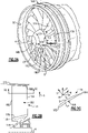
- the fan 50 includes a rotor 170 having an array or row 172 of airfoils or blades 174 that extend circumferentially around, and are supported by, the fan hub 176. Any suitable number of fan blades 174 may be used in a given application.
- the hub 176 is rotatable about the engine axis A.
- the array 172 of fan blades 174 are positioned about the axis A in a circumferential or tangential direction Y.
- Each of the blades 174 includes an airfoil body that extends in a radial span direction R from the hub 176 between a root 178 and a tip 180, in a chord direction H (axially and circumferentially) between a leading edge 182 and a trailing edge 184 and in a thickness direction T between a pressure side P and a suction side S.
- Each blade 174 has an exterior surface 188 providing a contour that extends from the leading edge 182 aftward in a chord-wise direction H to the trailing edge 184.
- the exterior surface 188 of the fan blade 174 generates lift based upon its geometry and directs flow along the core flow path and bypass flow path.
- the fan blade 174 may be constructed from a composite material, or an aluminum alloy or titanium alloy, or a combination of one or more of these. Abrasion-resistant coatings or other protective coatings may be applied to the fan blade 174.
- a chord represented by chord dimension (CD) is a straight line that extends between the leading edge 182 and the trailing edge 184 of the blade 174.
- the chord dimension (CD) may vary along the span of the blade 174.
- the row 172 of blades 174 also defines a circumferential pitch (CP) that is equivalent to the arc distance between the leading edges 182 or trailing edges 184 of neighboring blades 174 for a corresponding span position.
- the root 178 is received in a correspondingly shaped slot in the hub 176.
- the blade 174 extends radially outward of a platform 179, which provides the inner flow path.
- the platform 179 may be integral with the blade 174 or separately secured to the hub 176, for example.
- a spinner 185 is supported relative to the hub 176 to provide an aerodynamic inner flow path into the fan section 122.
- span positions are schematically illustrated from 0% to 100% in 10% increments to define a plurality of sections 181.
- Each section at a given span position is provided by a conical cut that corresponds to the shape of segments the bypass flowpath or the core flow path, as shown by the large dashed lines (shown in Figure 3A ).
- the 0% span position corresponds to the radially innermost location where the airfoil meets the fillet joining the airfoil to the platform 179.
- the 0% span position corresponds to the radially innermost location where the discrete platform 179 meets the exterior surface of the airfoil (shown in Figure 2B ).
- a 100% span position corresponds to a section of the blade 174 at the tip 80.
- each of the blades 174 defines a non-linear stacking axis 183 (shown in Figure 3B ) in the radial direction R between the tip 180 and the inner flow path location or platform 179.
- stacking axis refers to a line connecting the centers of gravity of airfoil sections 181.
- each fan blade 174 is specifically twisted about a spanwise axis in the radial direction R with a corresponding stagger angle at each span position and is defined with specific sweep and/or dihedral angles along the airfoil 174.
- Airfoil geometric shapes, stacking offsets, chord profiles, stagger angles, sweep, dihedral angles, and surface shape in an X, Y, Z coordinate system, among other associated features, can be incorporated individually or collectively to improve characteristics such as aerodynamic efficiency, structural integrity, and vibration mitigation, for example.
- the airfoil 174 defines an aerodynamic dihedral angle D (simply referred to as "dihedral") as schematically illustrated in Figure 3C .
- An axisymmetric stream surface S passes through the airfoil 174 at a location that corresponds to a span location ( Figure 3A ).
- the dihedral D relates to the angle at which a line L along the leading or trailing edge tilts with respect to the stream surface S.
- a plane P is normal to the line L and forms an angle with the tangential direction Y, providing the dihedral D.
- a positive dihedral D corresponds to the line tilting toward the suction side (suction side-leaning), and a negative dihedral D corresponds to the line tilting toward the pressure side (pressure side-leaning).
- each individual fan blade 174 defines multiple parameters such as chord dimension, radial span length, thickness, contour, circumferential pitch, stacking axis, stagger angle, sweep angle, and dihedral angle. Further, many of the example parameters as well as additional parameters can be required to meet tolerances at each of multiple span positions resulting in a substantial number of parameters, any one of which can disqualify the fan blade 174 if it is out of tolerance range under existing manufacturing processes. While described above with regards to the fan 50, and individual fan blades 174, it should be understood that similar parameters exist for any given blade and/or vane utilized through the engine 10, including those within the compressor section 20, and the turbine section 40.
- any number of other engine components can have similar numbers of parameters, all of which must be within tolerance, even if the parameters of the given component are not the same as the airfoil parameters described above. It is further recognized that normal wear, or wear as the result of damaging events, can impact the parameters of a fan blade that has been put in service in an engine. As a result of the wear, the fan blade can become disqualified, and a repair operation may be necessary to repair the blade.
- Designed parts are required to adhere to a design intent mean and accepted tolerances that would allow efficient assembly of the component from the set of parts produced by a vendor.
- each part needs to adhere to its design intent and variations are acceptable with a 3 ⁇ criteria and thus are expected to fall within a typical distribution curve (as illustrated in Figure 7 .)
- the parts should fall within the 99.73% region of the normal distribution as per design intent to ensure meeting design intent of part life and component performance metrics.
- the set of parts in a component like the fan or compressor all have to be within this accepted normal distribution to be introduced for assembly into the component and engine.
- one or more parameter may be out of tolerance either due to manufacturing variance or due to wear, but when the component is considered as a whole the component is still in an acceptable configuration. Further exacerbating this is the fact that different manufacturing techniques for any given component (e.g. additive manufacturing vs. casting) can result in different acceptable configurations, or different wear patterns, that may include one or more parameter outside of the as designed tolerances.
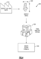
- Figure 4 schematically illustrates an exemplary system 300 for developing and analyzing a batch of as-run parts in order to determine a repair procedure for individual parts.
- a set of as-run parts that were manufactured using a single manufacturing process or uniform combination of processes is identified in an identify as-run parts step 310.
- each parameter of each of the as-run parts is measured in an inspect parts step 320.
- the inspect parts step 230 can be performed over a substantial period of time, as components are removed from aircraft engines during standard maintenance, or can be performed as a one-time maintenance instance for all the identified parts at the same time.
- the output of the inspect parts step 320 is a data set that includes a measurement of each parameter of each as-run part in the identified set.
- the as-run data set is then provided to a computer system and is used by the computer system to train a part analysis in a "train analysis system" step 330 within the train analysis step 330.
- the computer system develops a variance model that models the variations of an average, or exemplary as-run part, for the specific manufacturing process or processes and the specific wear case of the identified as-run part set, based on the set of measured as-run parts.
- the computer system develops a predictive model, that can predict the behavioral characteristics, such as efficiency, bending, vibration, etc. of a given component based on the specific parameters of that component and the engine in which the component is to be included.
- the specific parameters of the actual engine in which the component is to be included are utilized to develop the variance model in some examples.
- the variation model is a dimension reducing model, and describes a large number of observable variables' values using a smaller number of independent, latent variables.
- a latent variable is a variable whose value depends on our understanding of the latent structure inside the observed data.
- the latent structure of the data can only be determined from correlation analysis of the observed variables, and the correlation analysis requires observations of multiple as-manufactured parts.
- the usage of the as-run measurements of the set of as-run components to create the variance model and the predictive model can be referred to as a principal component analysis (PCA), and provides an accurate model of the actual wear patterns on a specific part design as well as an accurate model of the expected behavior of an actual part profile within an actual engine.
- the predictive model is a Gaussian Process (GP) model.
- the computer system then creates a repair formula in a "create repair formula" step 340.
- the repair formula is a function, or set of functions, that defines an acceptable component based on all of its parameters instead of being based on each parameter's individual tolerances.
- the computer system can automatically determine a blending operation, or other operation, to bring the as-run part within acceptable parameters. Due to the number of parameters (in some cases the number of parameters can exceed 20), and the number of positions on the part where each parameter is to be measured, the functions determined by the computer system are high order functions, and determining whether an individual component meets the functions would be prohibitively time consuming if performed manually.
- the repair formula can be utilized to verify manually designed repair operations to ensure that the resultant part dimension(s) meet acceptable parameters for the specific engine in which the resultant part will be included.
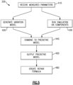
- Figure 5 schematically illustrates the "train analysis" step 330 of Figure 4 .
- a computer system receives all of the measured parameters of each component in the set of as-run components in a receive measured parameters step 410.
- the computer system can further determine one or more derived parameter based on a combination or manipulation of one or more of the measured parameters.
- the full data set is passed to a generate variation model operation 420 and a run simulation on components operation 430.
- the computer system determines a single variation model representative of the possible and/or expected variations of the specified component resulting from the particular wear case of the set of as-run parts.
- the variation model is representative of the general wear of all of the as-run parts in the entirety of the batch.
- the variation model can include an average figure, standard deviations, tolerances, and the like and be determined using any known process.
- the computer system iteratively runs a simulation where each of the components as-run is incorporated into a simulated engine, and a computer simulation is run to determine how the as-run component is expected to operate within a mathematical model of the simulated engine.
- the simulated engine is constructed based on expected dimensions and operations of a given engine model.
- the simulated engine is a computer model based on actual as-manufactured and as-run features of the specific engine in which the component to be repaired will be incorporated. The alternative example allows the system to more accurately account for the entirety of the component's operating environment in determining whether the repair profile is acceptable.
- the results of the simulation for each as-run component are compared and the variations in the parameters between each as-run component and each other as-run component are correlated with variations in the operation of the corresponding simulation results.
- the process moves to a combine to predictive model step 440.
- the correlated variations from simulation results are applied to the variation model generated in the generate variation model step 420 in order to determine a predictive model.
- the predictive model includes a mathematical function describing how any component fitting the variation model is expected to function within the simulated engine without requiring a technician to run the full simulation.
- the predictive model can include a Gaussian process.
- the mathematical functions describe how a component fitting the variation model is expected to function within that specific engine.
- the computer system uses the predictive model to create a repair formula which can be used to identify repairs for a specific as-run component created using the same manufacturing process, and exposed to the same general wear cycle, as the set of components used to train the analysis.
- "repair" of a component refers to determining how the component, as-run should be modified such that the as-run component can be utilized in a given engine and implementation of the determined modifications.
- the repair can include determining what type of repair procedure to apply in addition to what dimensions should be modified.
- the repair formula includes one or more mathematical functions, each of which relates multiple parameters of the as-run component to each other and generates a corresponding output value. In a typical example each of the functions within the repair formula is a higher order function.
- the train analysis step 330 utilizes a set of as-run components, all of which are manufactured using the same manufacturing process and exposed to generally the same wear pattern.
- generally the same wear pattern refers to engine components that have been operated in the same or similar engine configurations, and undergone the same or similar types of engine cycles.
- the set of as-run components includes at least 25 analyzed as-run components.
- at least 200 analyzed as-run components can be utilized.
- an initial set of as-run components can be supplemented with as-run components manufactured using the same process, and exposed to generally the same wear pattern, that are analyzed at a later date.
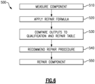
- Figure 6 schematically illustrates a process 500 for repairing an as-run component utilizing the repair formula determined during the final step of the train analysis process of Figure 4 .
- the individual component being checked for repair is measured in the same manner as the as-run components used to train the system in a measure component step 510.
- the measurement determines a measured value of each parameter of the component.
- the measured parameters are then applied to the repair formula in an apply repair formula step 520.
- Operating the repair formula using the measured parameters results in a number of outputs, with the number of outputs being equal to the number of functions within the repair formula.
- Each output represents a predicted performance result of a relationship between two or more of the measured parameters, and is associated with one or more repair procedure should the predicted performance be outside of accepted tolerances.
- the qualification and repair table includes a range of qualifying values for each function within the repair formula, and when each output is within the listed range, as determined in the comparison step 530, the component is qualified for the engine, and no repair is necessary. When one or more output values are outside of the range included in the qualification and repair table for that parameter, a suggested repair operation that can shift the parameters into the listed range is output in a recommend repair procedures step 540.
- the qualification and repair table can include multiple entries, each corresponding to a different specific engine and/or a different set of requirements for the engine. In such an example, the entry corresponding to the engine from which the as-run component was removed is utilized in the compare outputs to qualification and repair table step 530.
- the suggested repair procedure is output to a maintenance system, and causes the maintenance system to implement the repair.
- the maintenance system can be automated, semi-automated, or manual.
- a repair technician can then perform the recommended repair procedure, and bring the as-run component back into qualification.
- the repaired component can be measured and analyzed again to determine if the repaired component is acceptable and/or whether further repairs are necessary for the component to be qualified.
- the process 500 of Figure 6 is reiterated including measuring the as-repaired component.
- One advantage realized by the above system is the ability of the qualification and repair formula to identify, and institute repair procedures that account for all of the operational parameters of the as-run component. As a result certain repair profiles that may not meet a strict parameter by parameter tolerance check can still be utilized, further expanding the lifecycle of the as-run component.
- the number of times a blade can be repaired without requiring additional engineering analysis can be increased, thereby reducing the time and expenditure required to repair parts, as well as further reducing waste or scrap parts by decreasing the number of components that are disqualified rather than being repaired.
- the above repair system ensures that the parts adhere as closely as possible to design intent in part size, shape and toleranceing.
- the variation between the parts is more indicative of meeting the design intent than the variation from the center of the tolerance models. Skewed parts (i.e. parts that vary from each other by more than a design intent, while still fitting within tolerances) due to runaway repair process can cause degraded performance
Landscapes
- Engineering & Computer Science (AREA)
- Mechanical Engineering (AREA)
- Manufacturing & Machinery (AREA)
- Transportation (AREA)
- Aviation & Aerospace Engineering (AREA)
- Chemical & Material Sciences (AREA)
- Combustion & Propulsion (AREA)
- Physics & Mathematics (AREA)
- General Physics & Mathematics (AREA)
- General Engineering & Computer Science (AREA)
- Management, Administration, Business Operations System, And Electronic Commerce (AREA)
- Turbine Rotor Nozzle Sealing (AREA)
Claims (15)
- Reparatursystem (300) für Gasturbinentriebwerkskomponenten, Folgendes umfassend:ein Computersystem, das dazu konfiguriert ist, einen Satz gemessener Parameter für jede Gasturbinentriebwerkskomponente in einer Vielzahl von im Wesentlichen identischen Gasturbinentriebwerkskomponenten zu empfangen und ein Variationsmodell basierend auf dem Satz gemessener Parameter zu bestimmen, wobei jede der Gasturbinentriebwerkskomponenten eine Komponente wie aus dem laufenden Betrieb ist und einem im Wesentlichen identischen allgemeinen Verschleißmuster ausgesetzt war;wobei das Computersystem mindestens ein simuliertes Triebwerksmodell beinhaltet, wobei das simulierte Triebwerksmodell dazu konfiguriert ist, einen vorhergesagten Betrieb jeder Gasturbinentriebwerkskomponente in der Vielzahl von im Wesentlichen identischen Gasturbinentriebwerkskomponenten zu bestimmen;ein Korrelationssystem, das dazu konfiguriert ist, Variationen zwischen dem Satz von Parametern für jede der Gasturbinentriebwerkskomponenten und jede andere Turbinentriebwerkskomponente in der Vielzahl von im Wesentlichen identischen Gasturbinentriebwerkskomponenten mit einem Satz der vorhergesagten Betriebe jeder Gasturbinentriebwerkskomponente in der Vielzahl von im Wesentlichen identischen Gasturbinentriebwerkskomponenten zu korrelieren, wodurch ein Vorhersagemodell basierend auf den Variationen erzeugt wird; undein Reparaturmodul, das dazu konfiguriert ist, eine Reparaturformel basierend auf dem Vorhersagemodell zu erzeugen, wobei die Reparaturformel dazu konfiguriert ist, einen Satz gemessener Parameter einer Gasturbinentriebwerkskomponente wie aus dem laufenden Betrieb zu empfangen und eine vorgeschlagene Reparatur zu bestimmen, die in der Lage ist, die Gasturbinentriebwerkskomponente wie aus dem laufenden Betrieb zu reparieren.
- Reparatursystem nach Anspruch 1, wobei die Vielzahl von im Wesentlichen identischen Gasturbinentriebwerkskomponenten über ein einziges Herstellungsverfahren hergestellt wird.
- Reparatursystem nach Anspruch 2, wobei die Reparaturformel dazu konfiguriert ist, einen Reparaturvorgang einer Gasturbinentriebwerkskomponente wie aus dem laufenden Betrieb vorzuschlagen, die dem gleichen allgemeinen Verschleißmuster ausgesetzt ist wie die Vielzahl von im Wesentlichen identischen Gasturbinentriebwerkskomponenten.
- Reparatursystem nach einem der Ansprüche 1 bis 3, wobei die Vielzahl von im Wesentlichen identischen Gasturbinentriebwerkskomponenten mindestens 25 im Wesentlichen identische Turbinentriebwerkskomponenten und optional mindestens 200 im Wesentlichen identische Turbinentriebwerkskomponenten beinhaltet.
- Reparatursystem nach einem der Ansprüche 1 bis 4, wobei die Reparaturformel ein Satz mathematischer Funktionen ist, von denen jede mindestens zwei Parameter des Satzes gemessener Parameter für jede Gasturbinentriebwerkskomponente in Beziehung setzt.
- Reparatursystem nach einem vorhergehenden Anspruch, wobei die vorgeschlagene Reparatur eine Änderung mindestens eines der gemessenen Parameter der Gasturbinentriebwerkskomponente wie aus dem laufenden Betrieb ist.
- Reparatursystem nach Anspruch 6, wobei die vorgeschlagene Reparatur ferner mindestens ein vorgeschlagenes Verfahren zum Erzielen der Änderung des mindestens einen der gemessenen Parameter der Gasturbinentriebwerkskomponente wie aus dem laufenden Betrieb beinhaltet.
- Reparatursystem nach Anspruch 7, wobei der vorgeschlagene Prozess einen Mischvorgang beinhaltet.
- Reparatursystem nach einem vorhergehenden Anspruch, wobei das Reparaturmodul dazu konfiguriert ist, die Ausgangsgrößen der Reparaturformel mit einer Qualifizierungs- und Reparaturtabelle zu vergleichen und zu bestimmen, dass die Gasturbinentriebwerkskomponente wie aus dem laufenden Betrieb von einem Qualifizierungsparameter abweicht, wenn mindestens eine der Ausgangsgrößen außerhalb eines Satzes von Bereichen liegt, der in der Qualifizierungs- und Reparaturtabelle definiert ist, und wobei die vorgeschlagene Reparatur optional eine Prozedur ist, die die mindestens eine der Ausgangsgrößen, die außerhalb des Satzes von Bereichen liegt, der in der Qualifizierungs- und Reparaturtabelle definiert ist, innerhalb des Satzes von Bereichen bringt.
- Reparatursystem nach einem vorhergehenden Anspruch, wobei das Reparaturmodul dazu konfiguriert ist, die vorgeschlagene Reparatur einem Wartungssystem bereitzustellen, wodurch veranlasst wird, dass das Wartungssystem die vorgeschlagene Reparatur bewirkt.
- Reparatursystem nach einem vorhergehenden Anspruch, wobei das mindestens eine simulierte Triebwerksmodell eine Simulation eines tatsächlichen Triebwerks ist, in dem die Gasturbinentriebwerkskomponente wie aus dem laufenden Betrieb beinhaltet ist.
- Verfahren zum Reparieren einer Gasturbinentriebwerkskomponente, umfassend:Trainieren einer Reparaturformel mittels Empfangen eines Satzes gemessener Parameter (410) für jede Gasturbinentriebwerkskomponente in einem Satz von Gasturbinentriebwerkskomponenten wie aus dem laufenden Betrieb, wobei jede Gasturbinentriebwerkskomponente wie aus dem laufenden Betrieb das gleiche allgemeine Verschleißmuster aufweist, Erzeugen eines Variationsmodells (420) des Satzes von Gasturbinentriebwerkskomponenten wie aus dem laufenden Betrieb, Bestimmen einer simulierten Reaktion jeder der Gasturbinentriebwerkskomponenten wie aus dem laufenden Betrieb innerhalb eines simulierten Triebwerksmodells und Korrelieren von Variationen zwischen dem Satz von Parametern für jede der Gasturbinentriebwerkskomponenten wie aus dem laufenden Betrieb und jede andere Turbinentriebwerkskomponente in dem Satz von Gasturbinentriebwerkskomponenten wie aus dem laufenden Betrieb mit einem Satz der vorhergesagten Betriebe jeder Gasturbinentriebwerkskomponente in dem Satz von Gasturbinentriebwerkskomponenten wie aus dem laufenden Betrieb, wodurch ein Vorhersagemodells basierend auf den Variationen erzeugt wird; undErzeugen eines vorgeschlagenen Reparaturvorgangs für eine zweite Gasturbinentriebwerkskomponente für mindestens ein Triebwerk durch Bereitstellen eines Satzes gemessener Parameter der zweiten Gasturbinentriebwerkskomponente für die Reparaturformel, Vergleichen einer Vielzahl von Ausgangsgrößen aus der Reparaturformel mit einer Qualifizierungs- und Reparaturtabelle und Bestimmen des vorgeschlagenen Reparaturvorgangs, wenn mindestens eine Ausgangsgröße aus der Vielzahl von Ausgangsgrößen außerhalb eines ersten Satzes von Bereichen liegt, der in der Qualifizierungs- und Reparaturtabelle definiert ist.
- Verfahren nach Anspruch 12, ferner umfassend Durchführen des vorgeschlagenen Reparaturvorgangs an der zweiten Gasturbinentriebwerkskomponente; und/oder wobei die Vielzahl von Sätzen von Gasturbinentriebwerkskomponenten wie aus dem laufenden Betrieb mindestens 200 Gasturbinentriebwerkskomponenten beinhalten.
- Verfahren nach Anspruch 12 oder Anspruch 13, wobei jede der Gasturbinentriebwerkskomponenten in dem Satz von Gasturbinentriebwerkskomponenten wie aus dem laufenden Betrieb unter Verwendung eines einzigen Herstellungsverfahrens hergestellt wird und wobei optional die zweite Gasturbinentriebwerkskomponente dasselbe allgemeine Verschleißmuster wie jede Gasturbinentriebwerkskomponente wie aus dem laufenden Betrieb in dem Satz von Gasturbinentriebwerkskomponenten wie aus dem laufenden Betrieb aufweist.
- Verfahren nach einem der Ansprüche 12 bis 14, wobei die Reparaturformel einen Satz mathematischer Funktionen beinhaltet, von denen jede mindestens zwei Parameter des Satzes gemessener Parameter für jede Gasturbinentriebwerkskomponente in Beziehung setzt; und/oder wobei die vorgeschlagene Reparatur eine Prozedur ist, die die mindestens eine der Ausgangsgrößen, die außerhalb des Satzes von Bereichen liegt, der in der Qualifizierungs- und Reparaturtabelle definiert ist, innerhalb des Satzes von Bereichen bringt.
Applications Claiming Priority (1)
| Application Number | Priority Date | Filing Date | Title |
|---|---|---|---|
| US16/376,294 US12162627B2 (en) | 2019-04-05 | 2019-04-05 | Aircraft component repair system and process |
Publications (2)
| Publication Number | Publication Date |
|---|---|
| EP3719256A1 EP3719256A1 (de) | 2020-10-07 |
| EP3719256B1 true EP3719256B1 (de) | 2023-03-29 |
Family
ID=70165872
Family Applications (1)
| Application Number | Title | Priority Date | Filing Date |
|---|---|---|---|
| EP20167795.2A Active EP3719256B1 (de) | 2019-04-05 | 2020-04-02 | System und verfahren zur reparatur von flugzeugkomponenten |
Country Status (2)
| Country | Link |
|---|---|
| US (1) | US12162627B2 (de) |
| EP (1) | EP3719256B1 (de) |
Families Citing this family (3)
| Publication number | Priority date | Publication date | Assignee | Title |
|---|---|---|---|---|
| US11755791B2 (en) * | 2018-07-03 | 2023-09-12 | Rtx Corporation | Aircraft component qualification system and process |
| DE102020210308A1 (de) * | 2020-08-13 | 2022-02-17 | Siemens Healthcare Gmbh | Datenbasiertes Schätzen eines Betriebsverhaltens eines MR-Gerätes |
| FR3115018B1 (fr) * | 2020-10-08 | 2023-04-07 | Safran Aircraft Engines | Procédé de contrôle de l’opérationnalité d’une pièce mécanique d’un turboréacteur pour aéronef |
Family Cites Families (19)
| Publication number | Priority date | Publication date | Assignee | Title |
|---|---|---|---|---|
| US6850874B1 (en) * | 1998-04-17 | 2005-02-01 | United Technologies Corporation | Method and apparatus for predicting a characteristic of a product attribute formed by a machining process using a model of the process |
| US20020128790A1 (en) | 2001-03-09 | 2002-09-12 | Donald Woodmansee | System and method of automated part evaluation including inspection, disposition recommendation and refurbishment process determination |
| US6701615B2 (en) | 2002-03-08 | 2004-03-09 | General Electric Company | Inspection and sorting system and method for part repair |
| US7582359B2 (en) * | 2002-09-23 | 2009-09-01 | Siemens Energy, Inc. | Apparatus and method of monitoring operating parameters of a gas turbine |
| US6912446B2 (en) | 2002-10-23 | 2005-06-28 | General Electric Company | Systems and methods for automated sensing and machining for repairing airfoils of blades |
| US8004423B2 (en) * | 2004-06-21 | 2011-08-23 | Siemens Energy, Inc. | Instrumented component for use in an operating environment |
| US7824147B2 (en) | 2006-05-16 | 2010-11-02 | United Technologies Corporation | Airfoil prognosis for turbine engines |
| US9043795B2 (en) * | 2008-12-11 | 2015-05-26 | Qualcomm Incorporated | Apparatus and methods for adaptive thread scheduling on asymmetric multiprocessor |
| US20100257838A1 (en) * | 2009-04-09 | 2010-10-14 | General Electric Company | Model based health monitoring of aeroderivatives, robust to sensor failure and profiling |
| FR2952718B1 (fr) | 2009-11-17 | 2015-10-30 | Snecma | Systeme et procede de mesure de fatigue pour pieces mecaniques d'un aeronef et procede de maintenance de l'aeronef |
| GB2510816B (en) * | 2013-02-12 | 2015-04-08 | Rolls Royce Plc | Material removal method |
| GB2510635B (en) | 2013-02-12 | 2017-11-01 | Ge Aviat Systems Ltd | Method for predicting faults in an aircraft thrust reverser system |
| ITFI20130064A1 (it) * | 2013-03-26 | 2014-09-27 | Nuovo Pignone Srl | "methods and systems for controlling turbocompressors" |
| DE102016201764A1 (de) | 2016-02-05 | 2017-08-10 | MTU Aero Engines AG | Reparaturverfahren für Turbinenschaufeln |
| US10430531B2 (en) | 2016-02-12 | 2019-10-01 | United Technologies Corporation | Model based system monitoring |
| US10417614B2 (en) * | 2016-05-06 | 2019-09-17 | General Electric Company | Controlling aircraft operations and aircraft engine components assignment |
| US10754334B2 (en) * | 2016-05-09 | 2020-08-25 | Strong Force Iot Portfolio 2016, Llc | Methods and systems for industrial internet of things data collection for process adjustment in an upstream oil and gas environment |
| US9950815B2 (en) * | 2016-07-01 | 2018-04-24 | United Technologies Corporation | Systems and methods for detecting damage |
| US10496086B2 (en) * | 2016-12-12 | 2019-12-03 | General Electric Company | Gas turbine engine fleet performance deterioration |
-
2019
- 2019-04-05 US US16/376,294 patent/US12162627B2/en active Active
-
2020
- 2020-04-02 EP EP20167795.2A patent/EP3719256B1/de active Active
Also Published As
| Publication number | Publication date |
|---|---|
| EP3719256A1 (de) | 2020-10-07 |
| US20200317370A1 (en) | 2020-10-08 |
| US12162627B2 (en) | 2024-12-10 |
Similar Documents
| Publication | Publication Date | Title |
|---|---|---|
| EP3719721B1 (de) | System und verfahren zur planung der flugzeugkomponentenreparatur | |
| US11434764B2 (en) | Process for repairing turbine engine components | |
| EP3591173B1 (de) | Flugzeugkomponentenqualifizierungssystem und verfahren zur zielbasierten bestandsqualifikation | |
| EP3260656B1 (de) | Verfahren und system zur reparatur eines verdichterschaufelblatts | |
| EP3591172B1 (de) | Flugzeugkomponentenqualifikationssystem und -verfahren | |
| EP3719256B1 (de) | System und verfahren zur reparatur von flugzeugkomponenten | |
| CN108223137B (zh) | 用于确定燃气涡轮发动机机队性能劣化的系统和方法 | |
| US11568099B2 (en) | System and process for designing internal components for a gas turbine engine | |
| EP3255518A1 (de) | Verfahren zur herstellung und inspektion von gasgewaschenen komponenten in einem gasturbinenmotor | |
| CN107667280A (zh) | 机器部件的调度检查和预测寿命终止 | |
| EP3591174B1 (de) | System und verfahren zur qualifizierung von flugzeugkomponenten einschliesslich variationsmodellierung | |
| US20090255115A1 (en) | Method for developing a repair process to correct a deformed gas turbine engine component | |
| EP4257802A1 (de) | Strukturelles reparaturanalyse- system und verfahren für untersuchte beschaufelte rotoren | |
| Eulitz et al. | Design and validation of a compressor for a new generation of heavy-duty gas turbines | |
| EP4650569A2 (de) | Verfahren zur herstellung eines leitschaufelkranzes | |
| Evans et al. | Clearance sensitivity mitigation in small core compressors | |
| Botros et al. | NASA High Efficiency, High OPR Capable Small Core Compressor | |
| Voissel et al. | Aerodynamic Performance Prognosis of Operationally-Used Aero Engine Compressor Blading | |
| Ward et al. | SGT-400 industrial gas turbine power enhancement to 15MW design and product validation | |
| CN121145329A (zh) | 基于寿命的航空发动机维修性设计方法 | |
| van Rooij et al. | Engine Performance Prediction for Varied LPT Vane Geometry Utilizing Test Rig Data and Combined CFD and Cycle Models | |
| van Rooij et al. | Engine performance prediction for varied low pressure turbine vane geometry utilizing test rig data and combined computational fluid dynamic and cycle models |
Legal Events
| Date | Code | Title | Description |
|---|---|---|---|
| PUAI | Public reference made under article 153(3) epc to a published international application that has entered the european phase |
Free format text: ORIGINAL CODE: 0009012 |
|
| STAA | Information on the status of an ep patent application or granted ep patent |
Free format text: STATUS: THE APPLICATION HAS BEEN PUBLISHED |
|
| AK | Designated contracting states |
Kind code of ref document: A1 Designated state(s): AL AT BE BG CH CY CZ DE DK EE ES FI FR GB GR HR HU IE IS IT LI LT LU LV MC MK MT NL NO PL PT RO RS SE SI SK SM TR |
|
| AX | Request for extension of the european patent |
Extension state: BA ME |
|
| RIN1 | Information on inventor provided before grant (corrected) |
Inventor name: SELIN, EVAN Inventor name: LEVASSEUR, GLENN Inventor name: HEINEMANN, KURT R. Inventor name: SOMANATH, NAGENDRA |
|
| RAP1 | Party data changed (applicant data changed or rights of an application transferred) |
Owner name: RAYTHEON TECHNOLOGIES CORPORATION |
|
| STAA | Information on the status of an ep patent application or granted ep patent |
Free format text: STATUS: REQUEST FOR EXAMINATION WAS MADE |
|
| 17P | Request for examination filed |
Effective date: 20210407 |
|
| RBV | Designated contracting states (corrected) |
Designated state(s): AL AT BE BG CH CY CZ DE DK EE ES FI FR GB GR HR HU IE IS IT LI LT LU LV MC MK MT NL NO PL PT RO RS SE SI SK SM TR |
|
| GRAP | Despatch of communication of intention to grant a patent |
Free format text: ORIGINAL CODE: EPIDOSNIGR1 |
|
| STAA | Information on the status of an ep patent application or granted ep patent |
Free format text: STATUS: GRANT OF PATENT IS INTENDED |
|
| INTG | Intention to grant announced |
Effective date: 20221103 |
|
| GRAS | Grant fee paid |
Free format text: ORIGINAL CODE: EPIDOSNIGR3 |
|
| GRAA | (expected) grant |
Free format text: ORIGINAL CODE: 0009210 |
|
| STAA | Information on the status of an ep patent application or granted ep patent |
Free format text: STATUS: THE PATENT HAS BEEN GRANTED |
|
| AK | Designated contracting states |
Kind code of ref document: B1 Designated state(s): AL AT BE BG CH CY CZ DE DK EE ES FI FR GB GR HR HU IE IS IT LI LT LU LV MC MK MT NL NO PL PT RO RS SE SI SK SM TR |
|
| REG | Reference to a national code |
Ref country code: CH Ref legal event code: EP |
|
| REG | Reference to a national code |
Ref country code: DE Ref legal event code: R096 Ref document number: 602020009135 Country of ref document: DE |
|
| REG | Reference to a national code |
Ref country code: AT Ref legal event code: REF Ref document number: 1556789 Country of ref document: AT Kind code of ref document: T Effective date: 20230415 |
|
| REG | Reference to a national code |
Ref country code: IE Ref legal event code: FG4D |
|
| P01 | Opt-out of the competence of the unified patent court (upc) registered |
Effective date: 20230521 |
|
| REG | Reference to a national code |
Ref country code: LT Ref legal event code: MG9D |
|
| PG25 | Lapsed in a contracting state [announced via postgrant information from national office to epo] |
Ref country code: RS Free format text: LAPSE BECAUSE OF FAILURE TO SUBMIT A TRANSLATION OF THE DESCRIPTION OR TO PAY THE FEE WITHIN THE PRESCRIBED TIME-LIMIT Effective date: 20230329 Ref country code: NO Free format text: LAPSE BECAUSE OF FAILURE TO SUBMIT A TRANSLATION OF THE DESCRIPTION OR TO PAY THE FEE WITHIN THE PRESCRIBED TIME-LIMIT Effective date: 20230629 Ref country code: LV Free format text: LAPSE BECAUSE OF FAILURE TO SUBMIT A TRANSLATION OF THE DESCRIPTION OR TO PAY THE FEE WITHIN THE PRESCRIBED TIME-LIMIT Effective date: 20230329 Ref country code: LT Free format text: LAPSE BECAUSE OF FAILURE TO SUBMIT A TRANSLATION OF THE DESCRIPTION OR TO PAY THE FEE WITHIN THE PRESCRIBED TIME-LIMIT Effective date: 20230329 Ref country code: HR Free format text: LAPSE BECAUSE OF FAILURE TO SUBMIT A TRANSLATION OF THE DESCRIPTION OR TO PAY THE FEE WITHIN THE PRESCRIBED TIME-LIMIT Effective date: 20230329 |
|
| REG | Reference to a national code |
Ref country code: NL Ref legal event code: MP Effective date: 20230329 |
|
| REG | Reference to a national code |
Ref country code: AT Ref legal event code: MK05 Ref document number: 1556789 Country of ref document: AT Kind code of ref document: T Effective date: 20230329 |
|
| PG25 | Lapsed in a contracting state [announced via postgrant information from national office to epo] |
Ref country code: SE Free format text: LAPSE BECAUSE OF FAILURE TO SUBMIT A TRANSLATION OF THE DESCRIPTION OR TO PAY THE FEE WITHIN THE PRESCRIBED TIME-LIMIT Effective date: 20230329 Ref country code: NL Free format text: LAPSE BECAUSE OF FAILURE TO SUBMIT A TRANSLATION OF THE DESCRIPTION OR TO PAY THE FEE WITHIN THE PRESCRIBED TIME-LIMIT Effective date: 20230329 Ref country code: GR Free format text: LAPSE BECAUSE OF FAILURE TO SUBMIT A TRANSLATION OF THE DESCRIPTION OR TO PAY THE FEE WITHIN THE PRESCRIBED TIME-LIMIT Effective date: 20230630 Ref country code: FI Free format text: LAPSE BECAUSE OF FAILURE TO SUBMIT A TRANSLATION OF THE DESCRIPTION OR TO PAY THE FEE WITHIN THE PRESCRIBED TIME-LIMIT Effective date: 20230329 |
|
| PG25 | Lapsed in a contracting state [announced via postgrant information from national office to epo] |
Ref country code: SM Free format text: LAPSE BECAUSE OF FAILURE TO SUBMIT A TRANSLATION OF THE DESCRIPTION OR TO PAY THE FEE WITHIN THE PRESCRIBED TIME-LIMIT Effective date: 20230329 Ref country code: RO Free format text: LAPSE BECAUSE OF FAILURE TO SUBMIT A TRANSLATION OF THE DESCRIPTION OR TO PAY THE FEE WITHIN THE PRESCRIBED TIME-LIMIT Effective date: 20230329 Ref country code: PT Free format text: LAPSE BECAUSE OF FAILURE TO SUBMIT A TRANSLATION OF THE DESCRIPTION OR TO PAY THE FEE WITHIN THE PRESCRIBED TIME-LIMIT Effective date: 20230731 Ref country code: ES Free format text: LAPSE BECAUSE OF FAILURE TO SUBMIT A TRANSLATION OF THE DESCRIPTION OR TO PAY THE FEE WITHIN THE PRESCRIBED TIME-LIMIT Effective date: 20230329 Ref country code: EE Free format text: LAPSE BECAUSE OF FAILURE TO SUBMIT A TRANSLATION OF THE DESCRIPTION OR TO PAY THE FEE WITHIN THE PRESCRIBED TIME-LIMIT Effective date: 20230329 Ref country code: AT Free format text: LAPSE BECAUSE OF FAILURE TO SUBMIT A TRANSLATION OF THE DESCRIPTION OR TO PAY THE FEE WITHIN THE PRESCRIBED TIME-LIMIT Effective date: 20230329 |
|
| RAP4 | Party data changed (patent owner data changed or rights of a patent transferred) |
Owner name: RTX CORPORATION |
|
| PG25 | Lapsed in a contracting state [announced via postgrant information from national office to epo] |
Ref country code: SK Free format text: LAPSE BECAUSE OF FAILURE TO SUBMIT A TRANSLATION OF THE DESCRIPTION OR TO PAY THE FEE WITHIN THE PRESCRIBED TIME-LIMIT Effective date: 20230329 Ref country code: PL Free format text: LAPSE BECAUSE OF FAILURE TO SUBMIT A TRANSLATION OF THE DESCRIPTION OR TO PAY THE FEE WITHIN THE PRESCRIBED TIME-LIMIT Effective date: 20230329 Ref country code: IS Free format text: LAPSE BECAUSE OF FAILURE TO SUBMIT A TRANSLATION OF THE DESCRIPTION OR TO PAY THE FEE WITHIN THE PRESCRIBED TIME-LIMIT Effective date: 20230729 |
|
| REG | Reference to a national code |
Ref country code: CH Ref legal event code: PL |
|
| PG25 | Lapsed in a contracting state [announced via postgrant information from national office to epo] |
Ref country code: LU Free format text: LAPSE BECAUSE OF NON-PAYMENT OF DUE FEES Effective date: 20230402 |
|
| REG | Reference to a national code |
Ref country code: DE Ref legal event code: R097 Ref document number: 602020009135 Country of ref document: DE |
|
| REG | Reference to a national code |
Ref country code: BE Ref legal event code: MM Effective date: 20230430 |
|
| PG25 | Lapsed in a contracting state [announced via postgrant information from national office to epo] |
Ref country code: MC Free format text: LAPSE BECAUSE OF FAILURE TO SUBMIT A TRANSLATION OF THE DESCRIPTION OR TO PAY THE FEE WITHIN THE PRESCRIBED TIME-LIMIT Effective date: 20230329 |
|
| PG25 | Lapsed in a contracting state [announced via postgrant information from national office to epo] |
Ref country code: MC Free format text: LAPSE BECAUSE OF FAILURE TO SUBMIT A TRANSLATION OF THE DESCRIPTION OR TO PAY THE FEE WITHIN THE PRESCRIBED TIME-LIMIT Effective date: 20230329 Ref country code: LI Free format text: LAPSE BECAUSE OF NON-PAYMENT OF DUE FEES Effective date: 20230430 Ref country code: DK Free format text: LAPSE BECAUSE OF FAILURE TO SUBMIT A TRANSLATION OF THE DESCRIPTION OR TO PAY THE FEE WITHIN THE PRESCRIBED TIME-LIMIT Effective date: 20230329 Ref country code: CZ Free format text: LAPSE BECAUSE OF FAILURE TO SUBMIT A TRANSLATION OF THE DESCRIPTION OR TO PAY THE FEE WITHIN THE PRESCRIBED TIME-LIMIT Effective date: 20230329 Ref country code: CH Free format text: LAPSE BECAUSE OF NON-PAYMENT OF DUE FEES Effective date: 20230430 |
|
| PLBE | No opposition filed within time limit |
Free format text: ORIGINAL CODE: 0009261 |
|
| STAA | Information on the status of an ep patent application or granted ep patent |
Free format text: STATUS: NO OPPOSITION FILED WITHIN TIME LIMIT |
|
| REG | Reference to a national code |
Ref country code: IE Ref legal event code: MM4A |
|
| PG25 | Lapsed in a contracting state [announced via postgrant information from national office to epo] |
Ref country code: BE Free format text: LAPSE BECAUSE OF NON-PAYMENT OF DUE FEES Effective date: 20230430 |
|
| 26N | No opposition filed |
Effective date: 20240103 |
|
| PG25 | Lapsed in a contracting state [announced via postgrant information from national office to epo] |
Ref country code: IE Free format text: LAPSE BECAUSE OF NON-PAYMENT OF DUE FEES Effective date: 20230402 |
|
| PG25 | Lapsed in a contracting state [announced via postgrant information from national office to epo] |
Ref country code: IE Free format text: LAPSE BECAUSE OF NON-PAYMENT OF DUE FEES Effective date: 20230402 |
|
| PG25 | Lapsed in a contracting state [announced via postgrant information from national office to epo] |
Ref country code: SI Free format text: LAPSE BECAUSE OF FAILURE TO SUBMIT A TRANSLATION OF THE DESCRIPTION OR TO PAY THE FEE WITHIN THE PRESCRIBED TIME-LIMIT Effective date: 20230329 |
|
| PG25 | Lapsed in a contracting state [announced via postgrant information from national office to epo] |
Ref country code: SI Free format text: LAPSE BECAUSE OF FAILURE TO SUBMIT A TRANSLATION OF THE DESCRIPTION OR TO PAY THE FEE WITHIN THE PRESCRIBED TIME-LIMIT Effective date: 20230329 Ref country code: IT Free format text: LAPSE BECAUSE OF FAILURE TO SUBMIT A TRANSLATION OF THE DESCRIPTION OR TO PAY THE FEE WITHIN THE PRESCRIBED TIME-LIMIT Effective date: 20230329 |
|
| PG25 | Lapsed in a contracting state [announced via postgrant information from national office to epo] |
Ref country code: BG Free format text: LAPSE BECAUSE OF FAILURE TO SUBMIT A TRANSLATION OF THE DESCRIPTION OR TO PAY THE FEE WITHIN THE PRESCRIBED TIME-LIMIT Effective date: 20230329 |
|
| PG25 | Lapsed in a contracting state [announced via postgrant information from national office to epo] |
Ref country code: BG Free format text: LAPSE BECAUSE OF FAILURE TO SUBMIT A TRANSLATION OF THE DESCRIPTION OR TO PAY THE FEE WITHIN THE PRESCRIBED TIME-LIMIT Effective date: 20230329 |
|
| PGFP | Annual fee paid to national office [announced via postgrant information from national office to epo] |
Ref country code: DE Payment date: 20250319 Year of fee payment: 6 |
|
| PG25 | Lapsed in a contracting state [announced via postgrant information from national office to epo] |
Ref country code: CY Free format text: LAPSE BECAUSE OF FAILURE TO SUBMIT A TRANSLATION OF THE DESCRIPTION OR TO PAY THE FEE WITHIN THE PRESCRIBED TIME-LIMIT; INVALID AB INITIO Effective date: 20200402 |
|
| PG25 | Lapsed in a contracting state [announced via postgrant information from national office to epo] |
Ref country code: HU Free format text: LAPSE BECAUSE OF FAILURE TO SUBMIT A TRANSLATION OF THE DESCRIPTION OR TO PAY THE FEE WITHIN THE PRESCRIBED TIME-LIMIT; INVALID AB INITIO Effective date: 20200402 |
|
| REG | Reference to a national code |
Ref country code: DE Ref legal event code: R081 Ref document number: 602020009135 Country of ref document: DE Owner name: RTX CORPORATION (N.D.GES.D. STAATES DELAWARE),, US Free format text: FORMER OWNER: RAYTHEON TECHNOLOGIES CORP., FARMINGTON, CT, US |
|
| PG25 | Lapsed in a contracting state [announced via postgrant information from national office to epo] |
Ref country code: TR Free format text: LAPSE BECAUSE OF FAILURE TO SUBMIT A TRANSLATION OF THE DESCRIPTION OR TO PAY THE FEE WITHIN THE PRESCRIBED TIME-LIMIT Effective date: 20230329 |
|
| PGFP | Annual fee paid to national office [announced via postgrant information from national office to epo] |
Ref country code: GB Payment date: 20260319 Year of fee payment: 7 |
|
| PGFP | Annual fee paid to national office [announced via postgrant information from national office to epo] |
Ref country code: FR Payment date: 20260320 Year of fee payment: 7 |