EP3719311A1 - Alimentation en énergie pour capteurs dans une éolienne - Google Patents
Alimentation en énergie pour capteurs dans une éolienne Download PDFInfo
- Publication number
- EP3719311A1 EP3719311A1 EP19166599.1A EP19166599A EP3719311A1 EP 3719311 A1 EP3719311 A1 EP 3719311A1 EP 19166599 A EP19166599 A EP 19166599A EP 3719311 A1 EP3719311 A1 EP 3719311A1
- Authority
- EP
- European Patent Office
- Prior art keywords
- wind turbine
- sensor
- electrically connected
- energy harvester
- energy
- Prior art date
- Legal status (The legal status is an assumption and is not a legal conclusion. Google has not performed a legal analysis and makes no representation as to the accuracy of the status listed.)
- Withdrawn
Links
- 238000003860 storage Methods 0.000 claims abstract description 18
- 239000003990 capacitor Substances 0.000 claims description 5
- 238000005259 measurement Methods 0.000 description 2
- 230000003287 optical effect Effects 0.000 description 2
- 239000013307 optical fiber Substances 0.000 description 2
- 241001124569 Lycaenidae Species 0.000 description 1
- 238000010276 construction Methods 0.000 description 1
- 230000001419 dependent effect Effects 0.000 description 1
- 230000005611 electricity Effects 0.000 description 1
- 238000005516 engineering process Methods 0.000 description 1
- 238000009434 installation Methods 0.000 description 1
- 238000012423 maintenance Methods 0.000 description 1
- 230000014759 maintenance of location Effects 0.000 description 1
- 238000004377 microelectronic Methods 0.000 description 1
Images


Classifications
-
- F—MECHANICAL ENGINEERING; LIGHTING; HEATING; WEAPONS; BLASTING
- F03—MACHINES OR ENGINES FOR LIQUIDS; WIND, SPRING, OR WEIGHT MOTORS; PRODUCING MECHANICAL POWER OR A REACTIVE PROPULSIVE THRUST, NOT OTHERWISE PROVIDED FOR
- F03D—WIND MOTORS
- F03D80/00—Details, components or accessories not provided for in groups F03D1/00 - F03D17/00
- F03D80/80—Arrangement of components within nacelles or towers
- F03D80/82—Arrangement of components within nacelles or towers of electrical components
-
- F—MECHANICAL ENGINEERING; LIGHTING; HEATING; WEAPONS; BLASTING
- F03—MACHINES OR ENGINES FOR LIQUIDS; WIND, SPRING, OR WEIGHT MOTORS; PRODUCING MECHANICAL POWER OR A REACTIVE PROPULSIVE THRUST, NOT OTHERWISE PROVIDED FOR
- F03D—WIND MOTORS
- F03D17/00—Monitoring or testing of wind motors, e.g. diagnostics
-
- F—MECHANICAL ENGINEERING; LIGHTING; HEATING; WEAPONS; BLASTING
- F03—MACHINES OR ENGINES FOR LIQUIDS; WIND, SPRING, OR WEIGHT MOTORS; PRODUCING MECHANICAL POWER OR A REACTIVE PROPULSIVE THRUST, NOT OTHERWISE PROVIDED FOR
- F03D—WIND MOTORS
- F03D80/00—Details, components or accessories not provided for in groups F03D1/00 - F03D17/00
- F03D80/30—Lightning protection
-
- Y—GENERAL TAGGING OF NEW TECHNOLOGICAL DEVELOPMENTS; GENERAL TAGGING OF CROSS-SECTIONAL TECHNOLOGIES SPANNING OVER SEVERAL SECTIONS OF THE IPC; TECHNICAL SUBJECTS COVERED BY FORMER USPC CROSS-REFERENCE ART COLLECTIONS [XRACs] AND DIGESTS
- Y02—TECHNOLOGIES OR APPLICATIONS FOR MITIGATION OR ADAPTATION AGAINST CLIMATE CHANGE
- Y02E—REDUCTION OF GREENHOUSE GAS [GHG] EMISSIONS, RELATED TO ENERGY GENERATION, TRANSMISSION OR DISTRIBUTION
- Y02E10/00—Energy generation through renewable energy sources
- Y02E10/70—Wind energy
- Y02E10/72—Wind turbines with rotation axis in wind direction
Definitions
- the present invention relates to a device for providing energy supply to a sensor installed on a wind turbine. Particularly, but not exclusively, the present invention relates to a sensor a device for providing energy supply to a sensor installed in a blade for a wind turbine.
- the powering can be performed by means of optical energy, for example emitted by a laser and transported through an optical fiber.
- mechanical energy harvesters are known, for example based on MEMS (" Micro Electronic Mechanical System") technology, which use the kinetic energy of moving parts, for example the wind rotor of the wind turbine, to produce powering energy for the sensors installed in the wind turbine.
- Scope of the present invention is to provide an alternative to the above described systems for powering the sensors inside a wind turbine, which achieves a plurality of advantages with reference to the above cited prior art.
- the according to the present invention may be characterized by simplicity of construction and maintenance, efficiency and cost effectiveness.
- a wind turbine includes a tower, a nacelle, at least one rotatable blade and at least one sensor comprising an energy harvester and a sensing element for measuring a physical variable.
- the energy harvester includes:
- the sensing element may measure a physical variable which is relevant in a wind turbine, for example vibration, temperature, pressure, humidity or other.
- the sensor may be installed in any component of the wind turbine, for example any of the blades or the tower or the nacelle.
- the energy harvester of the present invention is based on collecting energy from available electromagnetic sources, which transmits electromagnetic signal in the wind turbine environment.
- Suitable electromagnetic sources for the energy harvester of the present invention may be, for example, radio frequency sources, like television and radio stations.
- the wind turbine further includes a transmitter for transmitting the electromagnetic signal to the receiving antenna of the energy harvester.
- the transmitter may include a transmitting antenna or a leaky feeder.
- leaky feeder it is meant a communications elongated component, which leaks an electromagnetic wave which is transmitted along the component.
- the leaky feeder may be constituted by a leaky coaxial cable or a leaky waveguide or a leaky stripline.
- the leaky feeder allows the electromagnetic signal to leak out of the leaky feeder along its length and to be made available to the energy harvester of the sensor.
- the energy harvester of the sensor according to the present invention allows avoiding the risks connected with cable connections, in particular during lighting.
- an energy harvester collecting energy from an electromagnetic signal is characterized by simpler and cheaper components.
- the energy harvester may further include a band-pass filter electrically connected between the receiving antenna and the rectifier.
- the band-pass filter may be used for selective choosing one band of frequency among the frequencies, which are available to the energy harvester.
- the senor further comprises a control circuit electrically connected between the electrical storage and the sensing element.
- the sensor may further comprise a sensor transmitter electrically connected to the control circuit.
- the sensor transmitter may be used to transmit information, for example measurement data, from the sensor.
- a leaky feeder may also be arranged for receiving the information sent by the sensor.
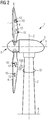
- FIGS 1 to 3 show respective embodiment of a wind turbine 1 for generating electricity.
- the wind turbine 1 includes one or more sensors 10 according to the invention.
- the wind turbine 1 comprises a tower 2 which is mounted on the ground 8 at one bottom end. At the opposite top end of the tower 2 there is mounted a nacelle 3.
- the nacelle 3 accommodates the electrical generator (not shown in the attached figures) of the wind turbine 1.
- a yaw angle adjustment device (not shown) is provided, which is capable of rotating the nacelle around a vertical yaw axis Z.
- the wind turbine 1 further comprises a wind rotor 5 having one or more rotational blades 4 (in the perspective of Figure 1 only two blades 4 are visible).
- the wind rotor 5 is rotatable around a rotational axis Y to transfer the rotational energy to the electrical generator of the nacelle 3.
- the generation of electrical power through the present invention is not a specific object of the present invention and therefore not described in further detail.
- the terms axial, radial and circumferential in the following are made with reference to the rotational axis Y.
- the blades 4 extend radially with respect to the rotational axis Y.
- each of the blades 4 includes two sensors 10 according to the present invention.
- the wind turbine 1 includes at least one sensor 10, which may be installed in any of the tower 2, the nacelle 3, one of the rotatable blades 4 and any other component of the wind turbine.
- Each sensor 10 includes a receiving antenna 12 for receiving an electromagnetic signal 100.
- the electromagnetic signal 100 is emitted by a transmitting antenna 51, installed on the nacelle 3.
- the electromagnetic signal 100 is emitted by a transmitting antenna 51 installed on the nacelle 3.
- the electromagnetic signal 100 is emitted by an electromagnetic signal source connected to a leaky feeder 52.
- the leaky feeder 52 allows the electromagnetic signal 100 to leak out of the leaky feeder along its length and to be made available to the receiving antenna 12.
- the leaky feeder 52 is configured as a loop attached to the tower 2. Such configuration permits that the emission of the electromagnetic signal 100 can be directed according to any direction around the vertical yaw axis Z.
- Figure 3 shows other possible installation of the leaky feeder 52 emitting the electromagnetic signal 100.
- the leaky feeder 52 emitting the electromagnetic signal 100.
- the leaky feeder 52 is configured as a closed loop, as shown in the embodiments of the figures 1 to 3 , or as an arc extending for less than 360 degrees.
- the wind turbine 1 may include any other transmitter for transmitting the electromagnetic signal 100 to the receiving antenna 12.
- the position of the transmitter may be chosen according to optimisation criteria, for example a position may be chosen which minimises the distance between the transmitter transmitting the electromagnetic signal 100 and the receiving antenna 12.
- the wind turbine 1 does not include any transmitter for transmitting the electromagnetic signal 100 to the receiving antenna 12, the electromagnetic signal 100 being emitted by an external electromagnetic signal source.
- the electromagnetic signal 100 may be emitted by radio frequency sources, like television and radio stations.
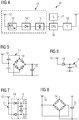
- FIG. 4 shows more in detail the sensor 10.
- the sensor 10 comprises an energy harvester 11 and a sensing element 17 for measuring a physical variable.
- the sensing element 17 measures any physical variable which is relevant in a wind turbine, for example vibration, temperature, pressure, humidity or other.
- the energy harvester 11 includes the receiving antenna 12. Attached to the receiving antenna 12, the energy harvester 11 comprises, electrically connected in series, a band-pass filter 13, a rectifier 14 and an electrical storage 15 for storing the electrical energy of the electromagnetic signal 100, which is harvested by the receiving antenna 12.
- the band-pass filter 13 electrically connected between the receiving antenna 12 and the rectifier 14 allows the energy harvester 11 to work in a chose range of frequency, for example far from the risk of interferences.
- a high-pass filter instead of the band-pass filter 13 may be used to select frequency above a threshold frequency, for example 10 MHz for avoiding lighting interferences.
- no filter is present between the receiving antenna 12 and the rectifier 14.
- the electrical storage 15 may comprises at least one capacitor. Alternatively, other the electrical storages may be used.
- the sensor 10 further comprises a control circuit 16 electrically connected between the electrical storage 15 and the sensing element 17.
- the control circuit 16 may comprise a CPU, an FPGA ("Field Programmable Gate Array") and other circuitry for serving the sensing element 17.
- the control circuit 16 may comprises further circuitry for serving a sensor transmitter 18 electrically connected to the control circuit 16.
- the sensor transmitter 18 comprises a transmitting antenna for transmitting information, for example measurement data, from the sensor 10 towards a receiver, which may be provided on the wind turbine 1.
- the receiver may be provided with a respective leaky feeder for receiving the information transmitted by the sensor 10.
- the electrical energy stored in the electrical storage 15 provides, when required, the powering for the control circuit 16, the sensing element 17 and the sensor transmitter 18.
- Figures 5 to 8 show four respective embodiments of the energy harvester 11. All the four respective embodiments of the figures 5 to 8 respectively include the receiving antenna 12, the rectifier 14 and the electrical storage 15.
- the rectifier 14 may include one simple diode ( figure 6 ), two diodes arranged in opposite direction in two respective branches connected in parallel to the receiving antenna 12 ( figure 7 ), a plurality of diodes ( figure 5 ) or a plurality of active switches, for example MOSFETs or JFETs.
- the energy harvester 11 may include any other type of rectifier 14, which is able to convert the wave signal provided by the receiving antenna 12 to a DC signal, to be transmitted to the electrical storage 15.
- the electrical storage 15 may comprise, for example, one single capacitor ( figures 5, 6 and 8 ), two capacitor ( figure 7 ), or a plurality of capacitors (embodiment not shown). According to other embodiments of the present invention (not shown), the energy harvester 11 may include any other type of electrical storage 15, which is able to store the energy of the DC signal provided by the rectifier 14.
Landscapes
- Engineering & Computer Science (AREA)
- Life Sciences & Earth Sciences (AREA)
- Sustainable Development (AREA)
- Sustainable Energy (AREA)
- Chemical & Material Sciences (AREA)
- Combustion & Propulsion (AREA)
- Mechanical Engineering (AREA)
- General Engineering & Computer Science (AREA)
- Wind Motors (AREA)
Priority Applications (5)
| Application Number | Priority Date | Filing Date | Title |
|---|---|---|---|
| EP19166599.1A EP3719311A1 (fr) | 2019-04-01 | 2019-04-01 | Alimentation en énergie pour capteurs dans une éolienne |
| PCT/EP2020/057069 WO2020200725A1 (fr) | 2019-04-01 | 2020-03-16 | Alimentation en énergie pour capteurs dans une éolienne |
| CN202080027079.0A CN113614367A (zh) | 2019-04-01 | 2020-03-16 | 针对风力涡轮机中的传感器的能量供给 |
| US17/442,643 US20220154701A1 (en) | 2019-04-01 | 2020-03-16 | Energy supply for sensors in a wind turbine |
| EP20714913.9A EP3927970A1 (fr) | 2019-04-01 | 2020-03-16 | Alimentation en énergie pour capteurs dans une éolienne |
Applications Claiming Priority (1)
| Application Number | Priority Date | Filing Date | Title |
|---|---|---|---|
| EP19166599.1A EP3719311A1 (fr) | 2019-04-01 | 2019-04-01 | Alimentation en énergie pour capteurs dans une éolienne |
Publications (1)
| Publication Number | Publication Date |
|---|---|
| EP3719311A1 true EP3719311A1 (fr) | 2020-10-07 |
Family
ID=66049093
Family Applications (2)
| Application Number | Title | Priority Date | Filing Date |
|---|---|---|---|
| EP19166599.1A Withdrawn EP3719311A1 (fr) | 2019-04-01 | 2019-04-01 | Alimentation en énergie pour capteurs dans une éolienne |
| EP20714913.9A Withdrawn EP3927970A1 (fr) | 2019-04-01 | 2020-03-16 | Alimentation en énergie pour capteurs dans une éolienne |
Family Applications After (1)
| Application Number | Title | Priority Date | Filing Date |
|---|---|---|---|
| EP20714913.9A Withdrawn EP3927970A1 (fr) | 2019-04-01 | 2020-03-16 | Alimentation en énergie pour capteurs dans une éolienne |
Country Status (4)
| Country | Link |
|---|---|
| US (1) | US20220154701A1 (fr) |
| EP (2) | EP3719311A1 (fr) |
| CN (1) | CN113614367A (fr) |
| WO (1) | WO2020200725A1 (fr) |
Cited By (1)
| Publication number | Priority date | Publication date | Assignee | Title |
|---|---|---|---|---|
| US11581847B2 (en) * | 2020-04-17 | 2023-02-14 | Henry Kamahoahoa FATA | Photovoltaic and electromagnetic powered mobile electric vehicle charging station |
Families Citing this family (1)
| Publication number | Priority date | Publication date | Assignee | Title |
|---|---|---|---|---|
| EP3719307A1 (fr) * | 2019-04-01 | 2020-10-07 | Siemens Gamesa Renewable Energy A/S | Système distribué et procédé de détection de la position et/ou de la vitesse d'une pale de rotor pendant le fonctionnement d'une éolienne |
Citations (1)
| Publication number | Priority date | Publication date | Assignee | Title |
|---|---|---|---|---|
| EP2551516A1 (fr) * | 2011-07-27 | 2013-01-30 | Siemens Aktiengesellschaft | Agencement et procédé pour fournir un alimentation électrique à un capteur |
Family Cites Families (17)
| Publication number | Priority date | Publication date | Assignee | Title |
|---|---|---|---|---|
| US6882128B1 (en) * | 2000-09-27 | 2005-04-19 | Science Applications International Corporation | Method and system for energy reclamation and reuse |
| CA2725065A1 (fr) * | 2008-05-20 | 2009-11-26 | Live Meters, Inc. | Systeme de surveillance et de commande a distance comprenant la technologie mesh et de synchronisation temporelle |
| WO2010036980A1 (fr) * | 2008-09-27 | 2010-04-01 | Witricity Corporation | Systèmes de transfert d'énergie sans fil |
| US20110158806A1 (en) * | 2009-04-15 | 2011-06-30 | Arms Steven W | Wind Turbines and Other Rotating Structures with Instrumented Load-Sensor Bolts or Instrumented Load-Sensor Blades |
| US8618934B2 (en) * | 2009-04-27 | 2013-12-31 | Kolos International LLC | Autonomous sensing module, a system and a method of long-term condition monitoring of structures |
| US20100315035A1 (en) * | 2009-06-13 | 2010-12-16 | Nickolai S. Belov | Autonomous Module with Extended Operational Life and Method Fabrication the Same |
| CN201653441U (zh) * | 2010-03-16 | 2010-11-24 | 中兴通讯股份有限公司 | 传感器 |
| US20110248846A1 (en) * | 2010-04-13 | 2011-10-13 | Green SHM Systems, Inc, Incorporated | Wireless Sensing Module and Method of Operation |
| US8568099B2 (en) * | 2010-12-17 | 2013-10-29 | Vestas Wind Systems A/S | Apparatus for harvesting energy from a gearbox to power an electrical device and related methods |
| US20120053851A1 (en) * | 2011-06-01 | 2012-03-01 | General Electric Company | System and method for monitoring turbine blade |
| US20180048178A1 (en) * | 2013-06-25 | 2018-02-15 | Energous Corporation | System and methods of using electromagnetic waves to wirelessly deliver power to electronic devices |
| TR201906940T4 (tr) * | 2012-10-30 | 2019-06-21 | Jain Irrigation Systems Ltd | Enerji hasadı ile hareket kontrol sistemi ve yöntemi. |
| CN103269132B (zh) * | 2013-05-23 | 2015-07-08 | 北京赛易科信息技术有限公司 | 传感器供电方法及供电装置 |
| CN103698741B (zh) * | 2013-10-11 | 2017-03-15 | 浙江大学 | 射频供电的电磁定位探头 |
| WO2015146705A1 (fr) * | 2014-03-25 | 2015-10-01 | Ntn株式会社 | Système de surveillance d'état |
| US10053218B2 (en) * | 2016-03-31 | 2018-08-21 | General Electric Company | System and method for positioning an unmanned aerial vehicle |
| US11725637B2 (en) * | 2017-08-22 | 2023-08-15 | University Of Maryland, Baltimore County | Apparatus and method for harvesting vibration energy from a rotating object |
-
2019
- 2019-04-01 EP EP19166599.1A patent/EP3719311A1/fr not_active Withdrawn
-
2020
- 2020-03-16 EP EP20714913.9A patent/EP3927970A1/fr not_active Withdrawn
- 2020-03-16 WO PCT/EP2020/057069 patent/WO2020200725A1/fr not_active Ceased
- 2020-03-16 CN CN202080027079.0A patent/CN113614367A/zh active Pending
- 2020-03-16 US US17/442,643 patent/US20220154701A1/en not_active Abandoned
Patent Citations (1)
| Publication number | Priority date | Publication date | Assignee | Title |
|---|---|---|---|---|
| EP2551516A1 (fr) * | 2011-07-27 | 2013-01-30 | Siemens Aktiengesellschaft | Agencement et procédé pour fournir un alimentation électrique à un capteur |
Non-Patent Citations (1)
| Title |
|---|
| APOSTOLOS GEORGIADIS ET AL: "Flexible hybrid solar/EM energy harvester for autonomous sensors", MICROWAVE SYMPOSIUM DIGEST (MTT), 2011 IEEE MTT-S INTERNATIONAL, IEEE, 5 June 2011 (2011-06-05), pages 1 - 4, XP032006910, ISBN: 978-1-61284-754-2, DOI: 10.1109/MWSYM.2011.5972963 * |
Cited By (1)
| Publication number | Priority date | Publication date | Assignee | Title |
|---|---|---|---|---|
| US11581847B2 (en) * | 2020-04-17 | 2023-02-14 | Henry Kamahoahoa FATA | Photovoltaic and electromagnetic powered mobile electric vehicle charging station |
Also Published As
| Publication number | Publication date |
|---|---|
| US20220154701A1 (en) | 2022-05-19 |
| WO2020200725A1 (fr) | 2020-10-08 |
| CN113614367A (zh) | 2021-11-05 |
| EP3927970A1 (fr) | 2021-12-29 |
Similar Documents
| Publication | Publication Date | Title |
|---|---|---|
| US20100221111A1 (en) | Wind turbine blade, wind turbine and method for manufacturing a wind turbine blade | |
| EP1788240B1 (fr) | Rotor pour une éolienne | |
| JP5968895B2 (ja) | 散水システム | |
| EP3719311A1 (fr) | Alimentation en énergie pour capteurs dans une éolienne | |
| US20220178785A1 (en) | Method and apparatus for performing measurements and monitoring of an object | |
| EP3841300B1 (fr) | Éolienne et méthode de détection de la position et/ou de la vitesse et/ou de la taille d'un objet | |
| EP2384017A2 (fr) | Procédé de mesure d'un paramètre opérationnel d'éolienne et dispositif de mesure | |
| US20220186713A1 (en) | Distributed system for and method of detecting position and/or speed of a rotor blade during operation of a wind turbine | |
| CN103345262B (zh) | 一种用于立体天线罩性能测试的转台随动跟踪对准装置 | |
| CN104297634A (zh) | 一种超高压在线监测系统 | |
| US20220228567A1 (en) | Apparatus for and method of detecting one or more properties of a rotor blade during operation of a wind turbine | |
| US20200162161A1 (en) | Wireless optical communication system between a rotating element and a fixed element | |
| US20120224966A1 (en) | System for monitoring the condition of rotor blades at wind turbines | |
| CN207660781U (zh) | 风力发电机的叶片监测系统及叶片 | |
| CN208140928U (zh) | 风廓线雷达机构以及系统 | |
| CN113614361A (zh) | 用于风力涡轮机的电磁测量 | |
| CN203037749U (zh) | 雷电监测装置及系统 | |
| US20240250440A1 (en) | Wireless communication rotary joint | |
| EP2436922A1 (fr) | Agencement pour alimenter électriquement un capteur dans une pale d'éolienne | |
| EP3719304A1 (fr) | Système de communication pour éolienne | |
| EP3719305A1 (fr) | Éolienne dotée d'un conducteur d'ondes de fuite pour navigation d'hélicoptère | |
| CN121770626A (zh) | 一种便携式微波光传输系统 | |
| CN104515886A (zh) | 一种电流互感器 | |
| CN111198057A (zh) | 风机叶片根部扭矩在线监测系统 | |
| KR20140032031A (ko) | 무선 전력 공급시스템을 갖춘 해상 풍력발전기 |
Legal Events
| Date | Code | Title | Description |
|---|---|---|---|
| PUAI | Public reference made under article 153(3) epc to a published international application that has entered the european phase |
Free format text: ORIGINAL CODE: 0009012 |
|
| STAA | Information on the status of an ep patent application or granted ep patent |
Free format text: STATUS: THE APPLICATION HAS BEEN PUBLISHED |
|
| AK | Designated contracting states |
Kind code of ref document: A1 Designated state(s): AL AT BE BG CH CY CZ DE DK EE ES FI FR GB GR HR HU IE IS IT LI LT LU LV MC MK MT NL NO PL PT RO RS SE SI SK SM TR |
|
| AX | Request for extension of the european patent |
Extension state: BA ME |
|
| STAA | Information on the status of an ep patent application or granted ep patent |
Free format text: STATUS: THE APPLICATION IS DEEMED TO BE WITHDRAWN |
|
| 18D | Application deemed to be withdrawn |
Effective date: 20210408 |