EP3719337A1 - Einheit zur übertragung des drehmoments für ein kraftfahrzeug - Google Patents
Einheit zur übertragung des drehmoments für ein kraftfahrzeug Download PDFInfo
- Publication number
- EP3719337A1 EP3719337A1 EP20169006.2A EP20169006A EP3719337A1 EP 3719337 A1 EP3719337 A1 EP 3719337A1 EP 20169006 A EP20169006 A EP 20169006A EP 3719337 A1 EP3719337 A1 EP 3719337A1
- Authority
- EP
- European Patent Office
- Prior art keywords
- torque transmission
- torque
- housing
- transmission module
- wet clutch
- Prior art date
- Legal status (The legal status is an assumption and is not a legal conclusion. Google has not performed a legal analysis and makes no representation as to the accuracy of the status listed.)
- Withdrawn
Links
- 230000005540 biological transmission Effects 0.000 title claims abstract description 53
- 239000012809 cooling fluid Substances 0.000 claims description 6
- 238000000034 method Methods 0.000 claims description 6
- 230000003213 activating effect Effects 0.000 claims description 3
- 238000001816 cooling Methods 0.000 description 7
- 238000007789 sealing Methods 0.000 description 6
- 230000004913 activation Effects 0.000 description 4
- 238000004026 adhesive bonding Methods 0.000 description 3
- 235000021183 entrée Nutrition 0.000 description 3
- 239000012530 fluid Substances 0.000 description 3
- 238000003466 welding Methods 0.000 description 3
- 238000002485 combustion reaction Methods 0.000 description 2
- 239000002826 coolant Substances 0.000 description 2
- 238000005096 rolling process Methods 0.000 description 2
- 241000287107 Passer Species 0.000 description 1
- 238000005119 centrifugation Methods 0.000 description 1
- 238000010276 construction Methods 0.000 description 1
- 238000013016 damping Methods 0.000 description 1
- 239000000446 fuel Substances 0.000 description 1
- 230000003068 static effect Effects 0.000 description 1
- 230000002123 temporal effect Effects 0.000 description 1
Images


Classifications
-
- F—MECHANICAL ENGINEERING; LIGHTING; HEATING; WEAPONS; BLASTING
- F16—ENGINEERING ELEMENTS AND UNITS; GENERAL MEASURES FOR PRODUCING AND MAINTAINING EFFECTIVE FUNCTIONING OF MACHINES OR INSTALLATIONS; THERMAL INSULATION IN GENERAL
- F16D—COUPLINGS FOR TRANSMITTING ROTATION; CLUTCHES; BRAKES
- F16D25/00—Fluid-actuated clutches
- F16D25/08—Fluid-actuated clutches with fluid-actuated member not rotating with a clutching member
- F16D25/082—Fluid-actuated clutches with fluid-actuated member not rotating with a clutching member the line of action of the fluid-actuated members co-inciding with the axis of rotation
- F16D25/087—Fluid-actuated clutches with fluid-actuated member not rotating with a clutching member the line of action of the fluid-actuated members co-inciding with the axis of rotation the clutch being actuated by the fluid-actuated member via a diaphragm spring or an equivalent array of levers
-
- F—MECHANICAL ENGINEERING; LIGHTING; HEATING; WEAPONS; BLASTING
- F16—ENGINEERING ELEMENTS AND UNITS; GENERAL MEASURES FOR PRODUCING AND MAINTAINING EFFECTIVE FUNCTIONING OF MACHINES OR INSTALLATIONS; THERMAL INSULATION IN GENERAL
- F16D—COUPLINGS FOR TRANSMITTING ROTATION; CLUTCHES; BRAKES
- F16D25/00—Fluid-actuated clutches
- F16D25/12—Details not specific to one of the before-mentioned types
- F16D25/123—Details not specific to one of the before-mentioned types in view of cooling and lubrication
-
- F—MECHANICAL ENGINEERING; LIGHTING; HEATING; WEAPONS; BLASTING
- F16—ENGINEERING ELEMENTS AND UNITS; GENERAL MEASURES FOR PRODUCING AND MAINTAINING EFFECTIVE FUNCTIONING OF MACHINES OR INSTALLATIONS; THERMAL INSULATION IN GENERAL
- F16D—COUPLINGS FOR TRANSMITTING ROTATION; CLUTCHES; BRAKES
- F16D2300/00—Special features for couplings or clutches
- F16D2300/12—Mounting or assembling
Definitions
- the invention relates to a torque transmission assembly for a motor vehicle intended to be installed in a transmission chain between a powertrain and a gearbox.
- the invention relates in particular to the field of motor vehicles of the heavy-duty type.
- motor vehicles comprising a torque transmission device arranged between an internal combustion engine and a gearbox.
- a torque transmission device comprises a torque input element coupled to the crankshaft of the internal combustion engine and a torque output element coupled to the gearbox, the torque input element and the control element.
- torque output being movable in relative rotation about an axis of rotation.
- Wet clutches, single or double, for heavy vehicles are known, in particular from EP2868942 A1 .
- This document discloses a clutch system housed in an open clutch housing which cooperates with a gearbox housing. There is a need to limit the size, in particular the axial size, of the clutch. There is also a need to facilitate the mounting of the clutch module in the transmission chain.
- the torque transmission assembly further comprises at least one of the activating member of the actuating device, a torsion damper, a hydraulic unit and a control system.
- the torque transmission assembly further comprises an electric motor of the propulsion unit.
- the module, respectively the assembly comprises a single clutch.
- the module, respectively the assembly comprises several clutches, in particular two clutches.
- the clutches can be radially or axially adjacent according to different embodiments.
- the subject of the invention is a method for mounting a torque transmission assembly as described above. The method comprises a step of installing the module in a housing of a gearbox.
- a first and a second disc carrier a first opening and a second opening, a first part and to and a second part, a first channel and a second channel. This is a simple indexing to differentiate and name similar but not identical elements.
- This indexing does not imply a priority of one element over another and such names can easily be interchanged without departing from the scope of the present description. This indexing does not imply a temporal order, for example, to assess the arrangement of the various elements, their operation, or even their realization.
- the figure 1 shows a torque transmission assembly 900 intended to be integrated into a transmission chain between a propulsion unit 105 and a gearbox 106.
- the assembly 900 comprising at least one wet clutch 1 and at least one actuator 3 of wet clutch.
- the clutch 1 and the associated actuating device 3 are housed in a housing 2.
- the clutch 1 and the housing partly form a transmission module 100 shown here before assembly.
- the transmission module 100 is shown assembled figure 2 .
- the assembly 900, respectively the module 100 may include a single wet clutch.
- the transmission assembly, respectively the module comprises at least two wet clutches, in particular two wet clutches arranged radially with respect to one another.
- the casing 2 comprises a first part 26 and a second part 25.
- the two parts 25 and 26, shown assembled on the Figure 2 can for example be assembled by riveting, screwing, welding, gluing or any suitable means known to those skilled in the art.
- the first part 26 of the housing 2, located on the gearbox side is in particular configured to house at least one clutch 1.
- This first part 26 has a first opening 29 configured to be crossed by a torque output element. 6.
- the opening 29 preferably has a guide surface 29A arranged to cooperate with the torque output element 6.
- the second part 25 of the housing 2, located on the side of the propulsion unit has a second opening 28 through which a torque input element 5 passes.
- the opening 28 preferably has a guide surface 28A arranged to cooperate with the. torque input element 5.
- the torque input element 5 is in the form of an intermediate shaft 50.
- the shaft 50 may include several portions, in particular cylindrical or tubular.
- a first end portion 51 in particular cylindrical, is arranged to be connected to the crankshaft.
- a second portion 52 adjacent to the first, is for example arranged to support a torsion damper 7.
- a third portion 53 is connected to the clutch 1.
- the first portion 51 has for example a first outer diameter.
- the second portion has a second outside diameter, the first diameter being for example smaller than the second diameter.
- the third portion 53 has a third outer diameter, the third diameter here being equal to the second diameter. In a variant not shown, the third diameter is here greater than the second diameter.
- the actuating device 3 is housed in the second part 25 of the housing. It is here in the form of a diaphragm 30. In a variant not shown, the actuating device is in the form of a piston 35.
- the clutch 1 and the housing partly form a transmission module 100 shown assembled figure 2 .
- the actuator 3 and the torque input element 5 also belong to the illustrated module 100.
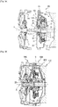
- the figures 3A and 3B illustrate a transmission assembly 900 before and after assembly between a powertrain 105 and a gearbox 106.
- the wet clutch 1 is here multi-discs and comprises a first disc holder 16 and a second disc holder 15.
- the first disc holder 16 is rotatably fixed to the torque output element 6. It can be fixed to the control element.
- the first disc carrier 16 is mounted to rotate relative to the housing 2 by means of a first bearing 11, in particular a rolling bearing 12.
- the first disc holder 16 is made in one piece with the torque output element 6.
- the second disc carrier 15 is rotatably mounted on the torque input element 5, in particular on the third portion 53 by means of a second bearing 11, in particular a rolling bearing 12.
- the input element of torque 5 is connected to at least one wet clutch 1, in particular to the second disc holder 15 of the wet clutch via a connecting element 55 located between the portion 53 and the second disc holder 15.
- the connecting element 55 is fixed to the second disc holder 15 by riveting as illustrated or by screwing, welding, gluing or any suitable means known to those skilled in the art.
- a third bearing 11, in particular an axial bearing 12 ', is arranged between the input element 5 and the output element 6.
- a first sealing means 9 is arranged between the input element 5 and the second part 25 of the housing 2 in which the second opening 28 is located.
- a second sealing means 9 is arranged between the outlet element 6 and the first part 26 of the casing 2.
- the first and second sealing means 9 are here dynamic seals, eg lip types.
- a third sealing means 9 is arranged between the first and second parts 26 and 25 of the casing 2. This third sealing means is in particular a static sealing means, here for example an O-ring.
- the first opening 29 and / or the second opening 28 has an internal surface 29A, respectively 28A, arranged to cooperate with the bearing 11 and seal 9 associated respectively with the torque output element 6 and with the 'torque input element 5.
- the figure 3A and figure 3B thus illustrate a method of mounting a torque transmission assembly according to the invention.
- the assembled module 100 is installed in a housing of the gearbox 106. This method is particularly advantageous and simplifies the assembly operations.
- the 900 transmission assembly shown in Figure 4 comprises a clutch module 100 as described above.
- the activation member 4 is here in the form of CSC 40.
- the assembly 900 comprises a hydraulic unit 600.
- the hydraulic unit 600 has a cooling circuit 620.
- the cooling circuit 620 may include a filter 625 and a heat exchanger 621.
- the hydraulic unit 600 also includes an actuation circuit 640.
- the hydraulic unit 600 comprises a first pump 61 connected to a first oil tank 61A for cooling the clutch module 100. It comprises a second pump 64 connected to a second oil tank 64A for controlling the engine. activation member 4.
- the first pump 61 is in particular a low pressure pump, the pressure being for example less than 5 bar, or even less than 3 bar, in particular between 0 and 2 bar.
- the second pump 64 is in particular a high pressure pump capable of delivering a pressure at least equal to 10 bar, or even greater than or equal to 15 bar, in particular greater than 20 bar.
- the control pressure is for example between 0 and 40 bar, in particular between 0 and 20 bar, or even between 0 and 10 bar.
- the control pressure can in particular be equal to 10 bar.
- the transmission assembly 900 includes a control system 700 configured to perform the control functions 720 of the cooling circuit 620 and the control functions 740 of the control circuit 640 of the clutch 1.
- the Figure 2 illustrates the cover 25 and a housing 26 of the clutch module 100 ..
- the module has ports 23 for connection with the hydraulic unit 600, partly outside the clutch module 100. These ports, here three in number, are arranged to be connected to a hydraulic control circuit 640, and to the cooling circuit 620 for the application of a cooling pressure, respectively of a cooling suction / actuation (negative pressure).
- two of the connection orifices 23 are located on the cover 25. They are used to supply the module 100. respectively via the first channel 21 for cooling fluid and via the second channel 22 for fluid to activate the activation member 4.
- the first disc holder 16 is here an internal disc holder and the second disc holder 15 is an external disc holder.
- the casing 2 comprises a first channel 21 configured to project a cooling fluid directly towards the internal disc holder 16.
- the first channel 21 is advantageously located, at least for its major part, in the first part 26 of the casing 2.
- the channel 21 communicates with the outside of the casing 2 via orifices 23.
- the cooling fluid is sprayed directly inside the casing 2 towards the first disc holder 16 via at least one orifice 24.
- the fluid is in particular projected into the casing by centrifugation linked to the rotation of said at least one of the torque input and output elements 5 and 6.
- the outer disc holder 15 of the wet clutch comprises a deflector 155 to facilitate the circulation of coolant and force it to pass through the clutch discs.
- an additional bearing is located between the deflector 155 and the housing 2.
- the housing 2 comprises several channels for supplying the cooling fluid to the clutch 1.
- the invention is not limited to the examples illustrated.
- the friction discs can be carried by the outer disc holder and the clutch discs carried by the internal disc holder or vice versa.
Landscapes
- Engineering & Computer Science (AREA)
- General Engineering & Computer Science (AREA)
- Mechanical Engineering (AREA)
- Mechanical Operated Clutches (AREA)
- Hydraulic Clutches, Magnetic Clutches, Fluid Clutches, And Fluid Joints (AREA)
- Arrangement Of Transmissions (AREA)
Applications Claiming Priority (1)
| Application Number | Priority Date | Filing Date | Title |
|---|---|---|---|
| FR1903632A FR3094767B1 (fr) | 2019-04-04 | 2019-04-04 | Ensemble de transmission de couple pour un véhicule automobile |
Publications (1)
| Publication Number | Publication Date |
|---|---|
| EP3719337A1 true EP3719337A1 (de) | 2020-10-07 |
Family
ID=68281501
Family Applications (1)
| Application Number | Title | Priority Date | Filing Date |
|---|---|---|---|
| EP20169006.2A Withdrawn EP3719337A1 (de) | 2019-04-04 | 2020-04-09 | Einheit zur übertragung des drehmoments für ein kraftfahrzeug |
Country Status (2)
| Country | Link |
|---|---|
| EP (1) | EP3719337A1 (de) |
| FR (1) | FR3094767B1 (de) |
Citations (3)
| Publication number | Priority date | Publication date | Assignee | Title |
|---|---|---|---|---|
| EP2868942A1 (de) | 2013-10-21 | 2015-05-06 | ZF Friedrichshafen AG | Lamellen-Kupplungseinrichtung |
| EP2998602A1 (de) * | 2014-09-18 | 2016-03-23 | Valeo Embrayages | Drehmoment-übertragungsmodul zur ausrüstung einer übertragung eines kraftfahrzeugs |
| WO2017051122A1 (fr) * | 2015-09-24 | 2017-03-30 | Valeo Embrayages | Ensemble de transmission de couple destine a équiper une transmission d'un véhicule automobile |
-
2019
- 2019-04-04 FR FR1903632A patent/FR3094767B1/fr not_active Expired - Fee Related
-
2020
- 2020-04-09 EP EP20169006.2A patent/EP3719337A1/de not_active Withdrawn
Patent Citations (3)
| Publication number | Priority date | Publication date | Assignee | Title |
|---|---|---|---|---|
| EP2868942A1 (de) | 2013-10-21 | 2015-05-06 | ZF Friedrichshafen AG | Lamellen-Kupplungseinrichtung |
| EP2998602A1 (de) * | 2014-09-18 | 2016-03-23 | Valeo Embrayages | Drehmoment-übertragungsmodul zur ausrüstung einer übertragung eines kraftfahrzeugs |
| WO2017051122A1 (fr) * | 2015-09-24 | 2017-03-30 | Valeo Embrayages | Ensemble de transmission de couple destine a équiper une transmission d'un véhicule automobile |
Also Published As
| Publication number | Publication date |
|---|---|
| FR3094767A1 (fr) | 2020-10-09 |
| FR3094767B1 (fr) | 2022-07-08 |
Similar Documents
| Publication | Publication Date | Title |
|---|---|---|
| EP2998602B1 (de) | Drehmoment-übertragungsmodul zur ausrüstung einer übertragung eines kraftfahrzeugs | |
| FR2803346A1 (fr) | Embrayage double, en particulier pour vehicule automobile | |
| EP3879133B1 (de) | Doppelnasskupplung | |
| EP3899300A1 (de) | Getriebevorrichtung für ein kraftfahrzeug | |
| FR2767371A1 (fr) | Convertisseur de couple comportant un embrayage a verrouillage, et son procede de fabrication | |
| FR3090774A1 (fr) | Dispositif de transmission pour véhicule automobile | |
| FR2814516A1 (fr) | Dispositif de transmission a engrenages, en particulier pour vehicule automobile | |
| FR2895770A1 (fr) | Amortisseur de torsion pour embrayage, en particulier de vehicule automobile. | |
| EP3719338A1 (de) | Modul zur übertragung des drehmoments für ein kraftfahrzeug | |
| FR3094767A1 (fr) | Ensemble de transmission de couple pour un véhicule automobile | |
| EP3353450A1 (de) | Drehmomentübertragungsanordnung für ein kraftfahrzeuggetriebe | |
| WO2019166515A1 (fr) | Dispositif de transmission pour vehicule hybride | |
| FR2881382A1 (fr) | Dispositif d'accouplement entre le rotor d'une machine electrique tournante reversible et l'arbre primaire de la boite de vitesses d'un moteur thermique d'un vehicule automobile | |
| FR3129189A1 (fr) | Embrayage humide amélioré pour système de groupe motopropulseur | |
| FR3111171A1 (fr) | Double embrayage humide | |
| FR2802154A1 (fr) | Systeme d'entrainement de l'arbre primaire de boite de vitesses pour un vehicule a propulsion hybride | |
| FR3090773A1 (fr) | Dispositif de transmission pour véhicule automobile | |
| FR3117063A1 (fr) | Dispositif de transmission de couple, en particulier pour véhicule automobile | |
| EP3857090B1 (de) | Kompakter doppelnasskupplungsmechanismus | |
| WO2022002631A1 (fr) | Module de transmission de couple | |
| EP4180681A1 (de) | Verbesserte nasskupplung für antriebsstrangsystem | |
| FR3102815A1 (fr) | Mecanisme d’embrayage multidisques comprenant une etancheite amelioree | |
| EP4261427A1 (de) | Verbesserte nasskupplung für antriebsstrangsystem | |
| EP2988014A1 (de) | Kupplungsvorrichtung für kraftfahrzeug | |
| WO2019154618A1 (fr) | Dispositif de transmission pour vehicule hybride |
Legal Events
| Date | Code | Title | Description |
|---|---|---|---|
| PUAI | Public reference made under article 153(3) epc to a published international application that has entered the european phase |
Free format text: ORIGINAL CODE: 0009012 |
|
| STAA | Information on the status of an ep patent application or granted ep patent |
Free format text: STATUS: THE APPLICATION HAS BEEN PUBLISHED |
|
| AK | Designated contracting states |
Kind code of ref document: A1 Designated state(s): AL AT BE BG CH CY CZ DE DK EE ES FI FR GB GR HR HU IE IS IT LI LT LU LV MC MK MT NL NO PL PT RO RS SE SI SK SM TR |
|
| AX | Request for extension of the european patent |
Extension state: BA ME |
|
| STAA | Information on the status of an ep patent application or granted ep patent |
Free format text: STATUS: REQUEST FOR EXAMINATION WAS MADE |
|
| 17P | Request for examination filed |
Effective date: 20210407 |
|
| STAA | Information on the status of an ep patent application or granted ep patent |
Free format text: STATUS: EXAMINATION IS IN PROGRESS |
|
| 17Q | First examination report despatched |
Effective date: 20221116 |
|
| P01 | Opt-out of the competence of the unified patent court (upc) registered |
Effective date: 20230528 |
|
| STAA | Information on the status of an ep patent application or granted ep patent |
Free format text: STATUS: THE APPLICATION IS DEEMED TO BE WITHDRAWN |
|
| 18D | Application deemed to be withdrawn |
Effective date: 20230527 |