EP3719366B1 - Organe de commande d'actionneur - Google Patents
Organe de commande d'actionneur Download PDFInfo
- Publication number
- EP3719366B1 EP3719366B1 EP19167471.2A EP19167471A EP3719366B1 EP 3719366 B1 EP3719366 B1 EP 3719366B1 EP 19167471 A EP19167471 A EP 19167471A EP 3719366 B1 EP3719366 B1 EP 3719366B1
- Authority
- EP
- European Patent Office
- Prior art keywords
- actuator
- input signal
- controller
- valve
- function
- Prior art date
- Legal status (The legal status is an assumption and is not a legal conclusion. Google has not performed a legal analysis and makes no representation as to the accuracy of the status listed.)
- Active
Links
Images

Classifications
-
- F—MECHANICAL ENGINEERING; LIGHTING; HEATING; WEAPONS; BLASTING
- F24—HEATING; RANGES; VENTILATING
- F24F—AIR-CONDITIONING; AIR-HUMIDIFICATION; VENTILATION; USE OF AIR CURRENTS FOR SCREENING
- F24F11/00—Control or safety arrangements
- F24F11/70—Control systems characterised by their outputs; Constructional details thereof
- F24F11/80—Control systems characterised by their outputs; Constructional details thereof for controlling the temperature of the supplied air
- F24F11/83—Control systems characterised by their outputs; Constructional details thereof for controlling the temperature of the supplied air by controlling the supply of heat-exchange fluids to heat-exchangers
- F24F11/84—Control systems characterised by their outputs; Constructional details thereof for controlling the temperature of the supplied air by controlling the supply of heat-exchange fluids to heat-exchangers using valves
-
- F—MECHANICAL ENGINEERING; LIGHTING; HEATING; WEAPONS; BLASTING
- F16—ENGINEERING ELEMENTS AND UNITS; GENERAL MEASURES FOR PRODUCING AND MAINTAINING EFFECTIVE FUNCTIONING OF MACHINES OR INSTALLATIONS; THERMAL INSULATION IN GENERAL
- F16K—VALVES; TAPS; COCKS; ACTUATING-FLOATS; DEVICES FOR VENTING OR AERATING
- F16K37/00—Special means in or on valves or other cut-off apparatus for indicating or recording operation thereof, or for enabling an alarm to be given
- F16K37/0025—Electrical or magnetic means
- F16K37/005—Electrical or magnetic means for measuring fluid parameters
-
- G—PHYSICS
- G05—CONTROLLING; REGULATING
- G05D—SYSTEMS FOR CONTROLLING OR REGULATING NON-ELECTRIC VARIABLES
- G05D7/00—Control of flow
- G05D7/06—Control of flow characterised by the use of electric means
- G05D7/0617—Control of flow characterised by the use of electric means specially adapted for fluid materials
- G05D7/0629—Control of flow characterised by the use of electric means specially adapted for fluid materials characterised by the type of regulator means
- G05D7/0635—Control of flow characterised by the use of electric means specially adapted for fluid materials characterised by the type of regulator means by action on throttling means
-
- F—MECHANICAL ENGINEERING; LIGHTING; HEATING; WEAPONS; BLASTING
- F24—HEATING; RANGES; VENTILATING
- F24D—DOMESTIC- OR SPACE-HEATING SYSTEMS, e.g. CENTRAL HEATING SYSTEMS; DOMESTIC HOT-WATER SUPPLY SYSTEMS; ELEMENTS OR COMPONENTS THEREFOR
- F24D19/00—Details
- F24D19/10—Arrangement or mounting of control or safety devices
- F24D19/1006—Arrangement or mounting of control or safety devices for water heating systems
- F24D19/1009—Arrangement or mounting of control or safety devices for water heating systems for central heating
- F24D19/1015—Arrangement or mounting of control or safety devices for water heating systems for central heating using a valve or valves
-
- F—MECHANICAL ENGINEERING; LIGHTING; HEATING; WEAPONS; BLASTING
- F24—HEATING; RANGES; VENTILATING
- F24F—AIR-CONDITIONING; AIR-HUMIDIFICATION; VENTILATION; USE OF AIR CURRENTS FOR SCREENING
- F24F2140/00—Control inputs relating to system states
- F24F2140/40—Damper positions, e.g. open or closed
Definitions
- the present disclosure relates to optimisations for valves within heating, ventilation, and/or air-conditioning system.
- the present disclosure focuses on improved control of actuators of such valves.
- HVAC heating, ventilation and/or air-conditioning
- Each circuit comprises one or several heating coils and/or cooling coils to provide heating and/or cooling to various parts of a structure.
- Terminal units generally are heating devices or cooling devices.
- a terminal unit of a domestic heating system can, for instance, be a radiator.
- Flow control valves are commonly employed in HVAC systems. These systems typically circulate a fluid such as water through a plurality of conduits in order to provide heating or cooling. The purpose of a flow control valve is to achieve a controlled flow of a fluid through the conduits of the circuit.
- the amount of water flowing through the valve is substantially governed by the position of a throttle.
- the position of the throttle is typically set by an actuator.
- the actuator sets the position of the throttle in response to a signal received from a controller.
- Actuators of valves can be powered via the mains or via a battery.
- battery life becomes paramount as it determines cycles for maintenance and/or replacement.
- a first way to extend battery life is to increase the capacity of a battery within a HVAC installation. This solution does, however, entail cost penalties.
- a second way to extend battery life is to lower the power intake of the valve actuator.
- a plethora of parameters influence the power intake of an actuator within a HVAC system. These parameters include, but are not limited to,
- a patent application 16/031,310 was filed on 10 July 2018 .
- the same application was published as US2019/018432A1 on 17 January 2019 .
- the application 16/031,310 deals with control gain automation.
- a valve assembly 1 is disclosed having an actuator 5 as well as a valve member 4.
- a controller 9 calculates valve positions. The controller 9 then sends instructions to the actuator 5 thereby moving the valve member 4. The instructions sent by the controller 9 depend on whether or not a flow rate signal exceeds a threshold value.
- the present disclosure teaches an actuator for a valve that maximises battery life.
- An actuator with maximum battery life alleviates the cost burden and the risks involved in maintenance and replacement activities. To that end, the actuator lowers frequencies of start and/or stop operations. Also, the actuator of the instant disclosure largely dispenses with direction reversals.
- the present disclosure teaches a controller for an actuator and a control method that improve on battery life.
- the actuator controller inhibits unnecessary operations of an actuator.
- the controller compares amplitudes of actuator operations to a threshold value. The actuator moves if an only if the amplitude exceeds the threshold value. Should the amplitude associated with an actuator operation be less than the threshold value, no operation of the actuator will be carried out.
- the actuator can, by way of non-limiting examples, move by half of the indicated amplitude or by a quarter of the indicated amplitude or by two thirds of the indicated amplitude.
- FIG 1 shows a valve assembly 1 having an inlet port 2 and an outlet port 3.
- a fluid path extends between the valve inlet port 2 and the valve outlet port 3 of a conduit 8.
- a valve member 4 is situated in the fluid path.
- FIG 1 shows the valve member 4 in a (partially) open position such that flow of a medium between the inlet port 2 and the outlet port 3 is enabled.
- Valve member 4 preferably also has a closed position to obturate fluid flow along the fluid path.
- Valve member 4 can also have a fully open position in which flow between the valve inlet port 2 and the valve outlet port 3 is fully enabled.
- valve member 4 can change continuously between its fully open and its fully closed positions. In an alternate embodiment, the position of valve member 4 can change in (a finite number of) discrete steps between fully open and fully closed.
- An actuator 5 directly or indirectly couples to valve member 4 to set its position.
- the actuator 5 can, by way of non-limiting example, be chosen from the group of solenoid actuator, voice coil, hydraulic actuator and/or pneumatic actuator.
- FIG 1 depicts an actuator 5 which axially displaces a valve member 4 as indicated by arrow 6.
- the instant disclosure also applies to valves and/or valve assemblies wherein the actuator 5 pivotally changes the position of valve member 4 such as butterfly valves.
- FIG 1 also depicts a site controller 7.
- the site controller 7 is preferably located remotely from the valve assembly 1. It is envisaged that the site controller 7 is located at least ten meters, or at least twenty meters, or even at least fifty meters from the valve assembly 1.
- the site controller 7 can, by way of non-limiting example, be a cloud computer.
- the site controller 7 advantageously comprises a thermostat and/or a smart thermostat and/or a building management system and/or an energy management system.
- the site controller 7 is a thermostat and/or is a smart thermostat and/or is a building management system and/or is an energy management system.
- the site controller 7 is in operative communication with an actuator controller 9.
- the site controller 7 communicates with the actuator controller 9 via suitable bus connections.
- the bus connection can be unidirectional from the site controller 7 to the actuator controller 9.
- the bus connection can also be bidirectional.
- the bus connection can be a wireless bus connection. It is envisaged that site controller 7 employs a suitable communication bus protocol, in particular a digital protocol, to communicate with the actuator controller 9.
- the actuator controller 9 and the site controller 7 ideally provide interfaces enabling (unidirectional and/or bidirectional) digital communication.
- the controller 9 advantageously comprises a microprocessor having a memory and a processing unit.
- the controller 9 is a microprocessor having a memory and a processing unit.
- the controller 9 comprises a microcontroller.
- the controller 9 is a microcontroller.
- the controller 9 comprises a processor 10 such as a 16-bit processor and/or a 32-bit processor and/or a 64-bit processor.
- the controller 9 advantageously comprises an arithmetic logic unit.
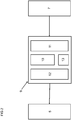
- the controller 9 as shown on FIG 2 also comprises an input interface 11.
- the input interface 11 affords communication with an external controller such as a site controller 7.
- the input interface 11 reads digital values.
- the input interface 11 reads analog values such as analog electric signals ranging from 0 Volt to 3 Volts and/or ranging from 0 Volt to 3.3 Volts and/or ranging from 0 Volt to 5 Volts. It is also envisaged that the input interface 11 reads electric currents ranging from 0 milliAmpere to 20 milliAmperes and/or from 4 milliAmperes to 20 milliAmperes.
- the input interface 11 advantageously comprises an analog-to-digital converter.
- the analog-to-digital of converter and the controller 9 are advantageously arranged on the same system-on-a-chip.
- the controller 9 as shown on FIG 2 also comprises an output interface 12.
- the output interface 12 affords communication with an external actuator such as a valve actuator 5.
- the output interface 12 sends digital values.
- the output interface 12 sends analog values such as analog electric signals ranging from 0 Volt to 3 Volts and/or ranging from 0 Volt to 3.3 Volts and/or ranging from 0 Volt to 5 Volts. It is also envisaged that the output interface 12 sends electric currents ranging from 0 milliAmpere to 20 milliAmperes and/or from 0 milliAmpere to 200 milliAmperes and/or ranging from 0 milliAmpere to 2000 milliAmperes.
- the output interface 12 advantageously comprises a digital-to-analog converter.
- the output interface 12 ideally also comprises an amplifier such as an operational amplifier.
- the controller 9 further comprises a memory 13 such as a non-volatile and/or a non-transient memory 13.
- the processor 10 has read-only access to the memory 13.
- a read-only configuration confers advantages in terms of reduced system complexity.
- the memory 13 can be a read-only memory.
- the processor 10 has read-write access to the memory 13.
- a read-write configuration confers advantages in terms of greater flexibility.
- a read-write configuration accommodates for parameter changes. Changed parameters can be stored in the memory 13 and will be available for processing at a later time.
- an actuator controller comprising:
- the second indicated actuator position preferably is different from the first indicated actuator position.
- the input interface (11) advantageously is a wireless interface. It is envisaged that the input interface (11) is configured to communicate with a site controller (7) using wireless communications such as wireless local area network(s), Bluetooth®, Zigbee®, etc.
- the input interface (11) communicating over a wireless bus advantageously provides a radio frequency module.
- the radio frequency module can be capable of phase-shift keying and/or of quaternary phase-shift keying. It is also envisaged that the radio frequency module improves on data transmission by limiting sizes of message blocks and/or by extra data redundancy. These functionalities may prove useful in environments wherein communication between the input interface (11) and a site controller (7) is hindered by obstacles such as thick concrete walls. These functionalities may also prove useful in environments wherein the input interface (11) communicates with a remote server over long distances.
- the processor (10) advantageously is configured to calculate a difference value as a difference between the actuator positions indicated by the first input signal and by the second input signal.
- the processor (10) more advantageously is configured to calculate a difference value as an absolute value of a difference between the actuator positions indicated by the first input signal and by the second input signal.
- the processor (10) ideally is configured to calculate a first output signal as a function of the first input signal and as a function of the second input signal. It is also envisaged that the processor (10) is configured to produce a first output signal as a function of the first input signal and as a function of the second input signal.
- the processor (10) is configured to: if and only if the difference value exceeds a predetermined threshold:
- the processor (10) is configured to: if and only if the difference value exceeds a predetermined threshold:
- an "if and only if a then b" condition means that
- the instant disclosure also teaches any of the aforementioned actuator controllers (9), wherein the processor (10) is configured to: determine the first output signal as a function of the first actuator position indicated by the first input signal and as a function of the difference value.
- the processor (10) ideally is configured to calculate the first output signal as a function of the first actuator position indicated by the first input signal and as a function of the difference value.
- the processor (10) is configured to: if and only if the difference value exceeds a predetermined threshold:
- the processor (10) is configured to: if and only if the difference value exceeds a predetermined threshold:
- the instant disclosure also teaches any of the aforementioned actuator controllers (9), wherein the processor (10) is configured to: determine the first output signal as a function of the first actuator position indicated by the first input signal and as a function of a fraction of the difference value.
- the processor (10) ideally is configured to calculate the first output signal as a function of the first actuator position indicated by the first input signal and as a function of a fraction of the difference value.
- the instant disclosure also teaches any of the aforementioned actuator controllers (9), wherein the processor (10) is configured to: determine the first output signal as a function of the first actuator position indicated by the first input signal and as a function of half or one third of the difference value.
- the processor (10) ideally is configured to calculate the first output signal as a function of the first actuator position indicated by the first input signal and as a function of half or one third of the difference value.
- the processor (10) is configured to: if and only if the difference value exceeds a predetermined threshold:
- the processor (10) is configured to: if and only if the difference value exceeds a predetermined threshold:
- the present disclosure also teaches any of the aforementioned actuator controllers (9), wherein the processor (10) is configured to: determine the first output signal as the sum of the first actuator position indicated by the first input signal and of the difference value divided by a positive integer larger than one such as divided by two, divided by three, etc.
- the processor (10) ideally is configured to calculate the first output signal as the sum of the first actuator position indicated by the first input signal and of the difference value divided by a positive integer larger than one such as divided by two, divided by three, etc.
- the processor (10) is configured to: if and only if the difference value exceeds a predetermined threshold:
- the processor (10) is configured to: if and only if the difference value exceeds a predetermined threshold:
- the instant disclosure also teaches any of the aforementioned actuator controllers (9), wherein the processor (10) is configured to:
- the third indicated actuator position advantageously is different from the second indicated actuator position and is different from the first indicated actuator position.
- the processor (10) ideally is configured to calculate a second output signal as a function of the third input signal.
- the processor (10) is configured to: if and only if the difference value exceeds a predetermined threshold:
- the processor (10) is configured to: if and only if the difference value exceeds a predetermined threshold:
- the instant disclosure also teaches the aforementioned actuator controller (9), wherein the processor (10) is configured to determine the second output signal as an exclusive function of the third actuator position indicated by the third input signal.
- the processor (10) ideally is configured to calculate the second output signal as an exclusive function of the third actuator position indicated by the third input signal.
- the processor (10) is configured to: if and only if the difference value exceeds a predetermined threshold:
- the processor (10) is configured to: if and only if the difference value exceeds a predetermined threshold:
- an exclusive function only takes the specified arguments. Whilst an exclusive function can take parameters, the number of arguments of the exclusive function is limited to the specified arguments.
- the instant disclosure also teaches any of the aforementioned actuator controllers (9), the actuator controller (9) comprising a memory (13), the processor (10) being in operative communication with the memory (13), wherein the processor (10) is configured to: read the predetermined threshold from the memory (13).
- the memory (13) is a non-volatile memory. It is also envisaged that the memory (13) is a non-transient memory. It is further envisaged that the memory (13) is a non-transitory memory.
- the present disclosure also teaches any of the aforementioned actuator controllers (9), wherein the input interface (11) comprises an analog-to-digital converter.
- the input interface (11) is an analog-to-digital converter.
- processor (10) and the input interface (11), the input interface (11) comprising an analog-to-digital converter are arranged on the same system-on-a-chip.
- the arrangement on the same system-on-a-chip is compact.
- processor (10) and the input interface (11), the input interface (11) being an analog-to-digital converter are arranged on the same system-on-a-chip.
- the arrangement on the same system-on-a-chip is compact.
- the instant disclosure further teaches any of the aforementioned actuator controllers (9), wherein the output interface (12) comprises a digital-to-analog converter.
- the output interface (12) is a digital-to-analog converter.
- processor (10) and the output interface (12) are arranged on the same system-on-a-chip. It is, in particular, envisaged that the processor (10) and the output interface (12), the output interface (12) comprising the digital-to-analog converter, are arranged on the same system-on-a-chip. It is further envisaged that the processor (10) and the output interface (12), the output interface (12) being a digital-to-analog converter, are arranged on the same system-on-a-chip. These arrangements on the same system-on-a-chip are compact thereby enabling miniaturised solutions.
- the present disclosure yet further teaches any of the aforementioned actuator controllers (9), wherein the output interface (12) comprises an amplifier.
- the amplifier comprises an operational amplifier and/or comprises a transistor amplifier and/or comprises an insulated-gate bipolar transistor.
- Amplifiers having insulated-gate bipolar transistors afford compatibility with complex waveforms having pulse-width-modulation.
- the output interface (12) comprises a digital-to-analog converter and an amplifier.
- the output interface (12) comprises a digital-to-analog converter, an amplifier such as an amplifier comprising an insulated-gate-bipolar-transistor, and a low-pass filter.
- the low-pass filter reduces electric stress on the windings of the valve actuator (5).
- processor (10) and the output interface (12) are arranged on the same system-on-a-chip. It is, in particular, envisaged that the processor (10) and the output interface (12), the output interface (12) comprising the digital-to-analog converter, are arranged on the same system-on-a-chip. It is further envisaged that the processor (10) and the output interface (12), the output interface (12) comprising the amplifier and comprising the digital-to-analog converter, are arranged on the same system-on-a-chip. These arrangements on the same system-on-a-chip are compact thereby enabling miniaturised solutions.
- the instant disclosure also teaches a valve assembly (1), the valve assembly (1) comprising: an inlet port (2), an outlet port (3), and a fluid path extending between the inlet port (2) and the outlet port (3); a valve member (4) acting on the fluid path, the valve member (4) being selectively movable between a closed position which closes the fluid path between the inlet port (2) and the outlet port (3), and an open position which opens the fluid path between the inlet port (2) and the outlet port (3); a valve actuator (5) for selectively moving the valve member (4) between the closed position and the open position; any of the actuator controllers (9) according to the instant disclosure, the actuator controller (9) being in operative communication with the valve actuator (5).
- valve member (4) is situated in the fluid path. It is also envisaged that the valve member (4) protrudes into the fluid path.
- valve actuator (5) advantageously mechanically couples to the valve member (4).
- the valve assembly (1) ideally comprises a conduit (8) such as a tubular conduit.
- the fluid path is then formed by the conduit (8).
- valve actuator (5) and the valve member (4) are secured relative to the valve assembly (1). According to a special aspect of the present disclosure, the valve actuator (5) and the valve member (4) are secured relative to the conduit (8).
- valve actuator (5) and the valve member (4) couple to the valve assembly (1).
- valve actuator (5) and the valve member (4) couple to the conduit (8).
- valve actuator (5) and the valve member (4) are mounted to the valve assembly (1). According to a special aspect of the present disclosure, the valve actuator (5) and the valve member (4) are mounted to the conduit (8).
- the actuator controller (9) is in operative communication with an external controller such as the site controller (7).
- the external controller such as the site controller (7) is typically located remotely from the valve assembly (1).
- valve assembly (1) additionally comprises a battery (14); wherein the battery (14) electrically connects to the valve actuator (5); and wherein the battery (14) is configured to supply the valve actuator (5) with power in order for the valve actuator (5) to selectively move the valve member (4) between the closed position and the open position.
- the battery (14) is secured relative to the valve assembly (1). According to a special aspect of the present disclosure, the battery (14) is secured relative to the conduit (8).
- the battery (14) is configured to supply the valve actuator (5) with electric power.
- the battery (14) is rechargeable.
- the battery (14) also electrically connects to the actuator controller (9).
- the battery (14) is thus configured to supply the actuator controller (9) with (electric) power.
- the battery (14) is a flow battery.
- Suitable flow batteries comprise, by way of non-limiting examples, hydrogen-lithium bromated batteries, hydrogen-lithium chlorate batteries, bromine-hydrogen batteries, iron-tin batteries, iron-titanium batteries, iron-chrome batteries, vanadium-vanadium (sulphate) batteries, vanadium-vanadium (bromide) batteries, sodium-bromine polysulfide batteries, zinc-bromine batteries, lead-acid (methanesulfonate) batteries and/or zinc-cerium (methanesulfonate) batteries.
- Suitable flow batteries can also comprise organic flow batteries such as batteries based on quinones. None of the above lists is exhaustive. Battery-powered valve assemblies (1) confer advantages in terms of improved autonomy.
- valve assembly (1) additionally comprising a bus (15), wherein the actuator controller (9) is in operative communication with the actuator (5) via the bus (15); wherein the bus (15) is configured to transmit the first output signal from the actuator controller (9) to the valve actuator (5); and is configured to transmit power in order for the valve actuator (5) to selectively move the valve member (4) between the closed position and the open position.
- the bus (15) is a communication bus such as a digital communication bus. It is also envisaged that the bus (15) is configured to transmit power such as electric power from the actuator controller (9) to the valve actuator (5) in order for the valve actuator (5) to selectively move the valve member (4) between the closed position and the open position.
- the bus (15) is configured to transmit power such as electric power from the valve actuator (5) to the actuator controller (9).
- the bus (15) is configured to transmit power such as electric power from the valve actuator (5) to the actuator controller (9) in order for the actuator controller (9) to execute instructions.
- the bus (15) is configured to transmit power such as electric power from the valve actuator (5) to the actuator controller (9) in order for the processor (10) of the actuator controller (9) to execute instructions.
- the present disclosure also teaches a method for controlling a valve actuator (5), the method comprising the steps of:
- the method advantageously comprises a step of calculating a difference value as a difference between the actuator positions indicated by the first input signal and by the second input signal.
- the method more advantageously comprises a step of calculating a difference value as an absolute value of a difference between the actuator positions indicated by the first input signal and by the second input signal.
- the method ideally comprises a step of calculating a first output signal as a function of the first input signal and as a function of the second input signal. It is also envisaged that the method comprises a step of producing a first output signal as a function of the first input signal and as a function of the second input signal.
- the method comprises the steps of: if and only if the difference value exceeds a predetermined threshold:
- the method comprises the steps of: if and only if the difference value exceeds a predetermined threshold:
- the method comprises the steps of: if and only if the difference value exceeds a predetermined threshold:
- the instant disclosure further teaches a tangible machine-readable medium (13) having a set of instructions stored thereon that when executed by one or more processors (10) cause the one or more processors (10) to perform any of the aforementioned methods.
- machine-readable medium (13) is non-transient. It is further envisaged that the machine-readable medium (13) is non-transitory.
- any steps of a method according to the present disclosure can be embodied in hardware, in a software module executed by a processor, in a software module being executed using operating-system-level virtualization, in a cloud computing arrangement, or in a combination thereof.
- the software can include a firmware, a hardware driver run in the operating system, or an application program.
- the disclosure also relates to a computer program product for performing the operations presented herein. If implemented in software, the functions described can be stored as one or more instructions on a computer-readable medium.
- RAM random access memory
- ROM read only memory
- flash memory EPROM memory
- EEPROM memory electrically erasable programmable read-only memory
- registers a hard disk, a removable disk, other optical disks, or any available media that can be accessed by a computer or any other IT equipment and appliance.
Landscapes
- Engineering & Computer Science (AREA)
- General Engineering & Computer Science (AREA)
- Mechanical Engineering (AREA)
- Chemical & Material Sciences (AREA)
- Combustion & Propulsion (AREA)
- Physics & Mathematics (AREA)
- General Physics & Mathematics (AREA)
- Automation & Control Theory (AREA)
- Indication Of The Valve Opening Or Closing Status (AREA)
Claims (15)
- Contrôleur d'actionneur (9) comprenant:une interface d'entrée (11) configurée pour recevoir des signaux d'entrée d'un contrôleur de site (7);une interface de sortie (12) configurée pour envoyer des signaux de sortie à un actionneur de soupape (5);un processeur (10) en communication fonctionnelle avec l'interface d'entrée (11) et en communication fonctionnelle avec l'interface de sortie (12), le processeur (10) étant configuré pour:utiliser l'interface d'entrée (11) pour lire un premier signal d'entrée indicateur d'une première position d'actionneur à partir du contrôleur de site (7);après la lecture du premier signal d'entrée, utiliser l'interface d'entrée (11) pour lire un second signal d'entrée indicateur d'une seconde position d'actionneur à partir du contrôleur de site (7);déterminer une valeur de différence indicatrice d'une différence entre les positions d'actionneur indiquées par le premier signal d'entrée et par le second signal d'entrée;déterminer un premier signal de sortie comme une fonction du premier signal d'entrée et comme une fonction du second signal d'entrée;caractérisé en ce quesi et seulement si la valeur de différence dépasse un seuil prédéterminé:
utiliser l'interface de sortie (12) pour envoyer le premier signal de sortie à l'actionneur de soupape (5). - Le contrôleur d'actionneur (9) selon la revendication 1, dans lequel le processeur (10) est configuré pour:
déterminer le premier signal de sortie comme une fonction de la première position d'actionneur indiquée par le premier signal d'entrée et comme une fonction de la valeur de différence. - Le contrôleur d'actionneur (9) selon la revendication 2, dans lequel le processeur (10) est configuré pour:
déterminer le premier signal de sortie comme une fonction de la première position d'actionneur indiquée par le premier signal d'entrée et comme une fonction d'une fraction de la valeur de différence. - Le contrôleur d'actionneur (9) selon la revendication 3, dans lequel le processeur (10) est configuré pour:
déterminer le premier signal de sortie comme la somme de la première position d'actionneur indiquée par le premier signal d'entrée et la valeur de différence divisée par un nombre entier positif supérieur à un. - Le contrôleur d'actionneur (9) selon l'une quelconque des revendications 1 à 4, dans lequel le processeur (10) est configuré pour:après la lecture du second signal d'entrée, utiliser l'interface d'entrée (11) pour lire un troisième signal d'entrée indicateur d'une troisième position d'actionneur à partir du contrôleur de site (7);déterminer un second signal de sortie comme une fonction du troisième signal d'entrée; etsi et seulement si la valeur de différence excède un seuil prédéterminé:
utiliser l'interface de sortie (12) pour envoyer le second signal de sortie à l'actionneur de soupape (5). - Le contrôleur d'actionneur (9) selon la revendication 5, dans lequel le processeur (10) est configuré pour déterminer le second signal de sortie comme une fonction exclusive de la troisième position d'actionneur indiquée par le troisième signal d'entrée.
- Le contrôleur d'actionneur (9) selon l'une quelconque des revendications 1 à 6, le contrôleur d'actionneur (9) comprenant une mémoire (13), le processeur (10) étant en communication fonctionnelle avec la mémoire (13), dans lequel le processeur (10) est configuré pour:
lire le seuil prédéterminé à partir de la mémoire (13). - Le contrôleur d'actionneur (9) selon l'une quelconque des revendications 1 à 7, dans lequel l'interface d'entrée (11) comprend un convertisseur analogique-numérique.
- Le contrôleur d'actionneur (9) selon l'une quelconque des revendications 1 à 8, dans lequel l'interface de sortie (12) comprend un convertisseur numérique-analogique.
- Le contrôleur d'actionneur (9) selon l'une quelconque des revendications 1 à 9, dans lequel l'interface de sortie (12) comprend un amplificateur.
- Ensemble soupape (1) comprenant:un port d'entrée (2), un port de sortie (3), et un trajet de liquide s'étendant entre le port d'entrée (2) et le port de sortie (3);un élément de soupape (4) agissant sur le trajet de liquide, l'élément de soupape (4) étant déplaçable de manière sélective entre une position fermée qui ferme le trajet de liquide entre le port d'entrée (2) et le port de sortie (3), et une position ouverte qui ouvre le trajet de liquide entre le port d'entrée (2) et le port de sortie (3);un actionneur de soupape (5) pour déplacer de manière sélective l'élément de soupape (4) entre la position fermée et la position ouverte;un contrôleur d'actionneur (9) selon l'une quelconque des revendications 1 à 10, le contrôleur d'actionneur (9) étant en communication fonctionnelle avec l'actionneur de soupape (5).
- L'ensemble soupape (1) selon la revendication 11,
dans lequel l'ensemble soupape (1) comprend de manière additionnelle une batterie (14);
dans lequel la batterie (14) se connecte de manière électrique à l'actionneur de soupape (5); et
dans lequel la batterie (14) est configurée pour fournir à l'actionneur de soupape (5) de l'énergie de manière que l'actionneur de soupape (5) déplace de manière sélective l'élément de soupape (4) entre la position fermée et la position ouverte. - L'ensemble soupape (1) selon l'une quelconque des revendications 11 à 12, l'ensemble soupape (1) comprenant de manière additionnelle un bus (15),
dans lequel le contrôleur d'actionneur (9) est en communication fonctionnelle avec l'actionneur (5) via le bus (15);
dans lequel le bus (15) est configuré pour transmettre le premier signal de sortie du contrôleur d'actionneur (9) à l'actionneur de soupape (5); et
est configuré pour transmettre de l'énergie de manière que l'actionneur de soupape (5) déplace de manière sélective l'élément de soupape (4) entre la position fermée et la position ouverte. - Procédé de commande d'un actionneur de soupape (5), le procédé comprenant les étapes de:recevoir un premier signal d'entrée indicateur d'une première position d'actionneur d'un contrôleur de site (7);après la réception du premier signal d'entrée, récevoir un second signal d'entrée indicateur d'une seconde position d'actionneur à partir du contrôleur de site (7);déterminer une valeur de différence indicatrice d'une différence entre les positions d'actionneur indiquées par le premier signal d'entrée et par le second signal d'entrée;déterminer un premier signal de sortie comme une fonction du premier signal d'entrée et comme une fonction du second signal d'entrée;caractérisé en ce quesi et seulement si la valeur de différence excède un seuil prédéterminé:
envoyer le premier signal de sortie à un actionneur de soupape (5). - Support tangible lisible par machine (13) ayant un jeu d'instructions stockées dessus qui lorsqu'exécutées par un ou plusieurs processeurs (10) amènent le un ou plusieurs processeurs (10) à réaliser le procédé selon la revendication 14.
Priority Applications (3)
| Application Number | Priority Date | Filing Date | Title |
|---|---|---|---|
| DK19167471.2T DK3719366T3 (da) | 2019-04-05 | 2019-04-05 | Aktuatorstyreenhed |
| EP19167471.2A EP3719366B1 (fr) | 2019-04-05 | 2019-04-05 | Organe de commande d'actionneur |
| ES19167471T ES2875897T3 (es) | 2019-04-05 | 2019-04-05 | Controlador de accionador |
Applications Claiming Priority (1)
| Application Number | Priority Date | Filing Date | Title |
|---|---|---|---|
| EP19167471.2A EP3719366B1 (fr) | 2019-04-05 | 2019-04-05 | Organe de commande d'actionneur |
Publications (2)
| Publication Number | Publication Date |
|---|---|
| EP3719366A1 EP3719366A1 (fr) | 2020-10-07 |
| EP3719366B1 true EP3719366B1 (fr) | 2021-03-24 |
Family
ID=66101879
Family Applications (1)
| Application Number | Title | Priority Date | Filing Date |
|---|---|---|---|
| EP19167471.2A Active EP3719366B1 (fr) | 2019-04-05 | 2019-04-05 | Organe de commande d'actionneur |
Country Status (3)
| Country | Link |
|---|---|
| EP (1) | EP3719366B1 (fr) |
| DK (1) | DK3719366T3 (fr) |
| ES (1) | ES2875897T3 (fr) |
Family Cites Families (5)
| Publication number | Priority date | Publication date | Assignee | Title |
|---|---|---|---|---|
| US3901310A (en) * | 1973-11-27 | 1975-08-26 | Johnson Service Co | Multizone environmental control system |
| US9641122B2 (en) * | 2012-06-26 | 2017-05-02 | Johnson Controls Technology Company | HVAC actuator with automatic end stop recalibration |
| ES2791888T3 (es) * | 2015-07-03 | 2020-11-06 | Siemens Schweiz Ag | Control de calefacción, ventilación y aire acondicionado |
| CN110520680B (zh) * | 2017-02-22 | 2021-12-14 | 江森自控科技公司 | 集成式智能致动器装置 |
| DK3428767T3 (da) | 2017-07-11 | 2020-03-02 | Siemens Schweiz Ag | Automatisering af styreforstærkning |
-
2019
- 2019-04-05 DK DK19167471.2T patent/DK3719366T3/da active
- 2019-04-05 ES ES19167471T patent/ES2875897T3/es active Active
- 2019-04-05 EP EP19167471.2A patent/EP3719366B1/fr active Active
Non-Patent Citations (1)
| Title |
|---|
| None * |
Also Published As
| Publication number | Publication date |
|---|---|
| EP3719366A1 (fr) | 2020-10-07 |
| DK3719366T3 (da) | 2021-06-07 |
| ES2875897T3 (es) | 2021-11-11 |
Similar Documents
| Publication | Publication Date | Title |
|---|---|---|
| EP3784959B1 (fr) | Dispositif de régulation de débit pour système de transport de fluide hvac | |
| EP3428767B1 (fr) | Automatisation de gain de commande | |
| JP6114680B2 (ja) | タービン式流量制御装置 | |
| CN102954557B (zh) | 一种空调系统 | |
| CN104390323A (zh) | 一种空调系统的温差电动调节阀及其温差控制方法 | |
| CN103813698A (zh) | 一种机柜制冷控制方法及系统 | |
| US20170241661A1 (en) | Predictive free cooling | |
| CN111365931A (zh) | 一种工业冷却水平衡优化节能控制系统 | |
| CN202171052U (zh) | 用于阀门电动执行器的智能控制器 | |
| CN203223626U (zh) | 一种阀门的调试系统 | |
| CN103823493A (zh) | 液力驱动风扇热管理系统控制装置及其控制方法 | |
| EP3719366B1 (fr) | Organe de commande d'actionneur | |
| US20160290152A1 (en) | Turbine-type flow rate controlling device | |
| CN204009609U (zh) | 液力驱动风扇热管理系统控制装置 | |
| CN105865105A (zh) | 冷冻水二次泵系统的控制方法和装置 | |
| US10731871B2 (en) | Retrofit smart components for use in a fluid transfer system | |
| CN106444495A (zh) | 一种用于集中供热的多功能智能控制终端系统 | |
| CN110285556B (zh) | 多功能热水机控制系统、方法和装置 | |
| JP6092855B2 (ja) | 暖房、換気および/または空調装置並びにそれを用いたキット | |
| CN113747468B (zh) | 电子设备的控制方法、LoRa网关、电子设备及存储介质 | |
| WO2023148302A1 (fr) | Procédé de communication entre un ordinateur distant et des dispositifs cvc de chauffage, de ventilation et de climatisation | |
| CN212227479U (zh) | 一种工业冷却水平衡优化节能控制系统 | |
| CN114148499A (zh) | 一种船舶淡水冷却自动控制系统及方法 | |
| CN204678603U (zh) | 一种主动调节冷热水机组负荷的控制系统 | |
| CN207661935U (zh) | 一种空调控制系统 |
Legal Events
| Date | Code | Title | Description |
|---|---|---|---|
| PUAI | Public reference made under article 153(3) epc to a published international application that has entered the european phase |
Free format text: ORIGINAL CODE: 0009012 |
|
| STAA | Information on the status of an ep patent application or granted ep patent |
Free format text: STATUS: REQUEST FOR EXAMINATION WAS MADE |
|
| 17P | Request for examination filed |
Effective date: 20191004 |
|
| AK | Designated contracting states |
Kind code of ref document: A1 Designated state(s): AL AT BE BG CH CY CZ DE DK EE ES FI FR GB GR HR HU IE IS IT LI LT LU LV MC MK MT NL NO PL PT RO RS SE SI SK SM TR |
|
| AX | Request for extension of the european patent |
Extension state: BA ME |
|
| GRAP | Despatch of communication of intention to grant a patent |
Free format text: ORIGINAL CODE: EPIDOSNIGR1 |
|
| STAA | Information on the status of an ep patent application or granted ep patent |
Free format text: STATUS: GRANT OF PATENT IS INTENDED |
|
| INTG | Intention to grant announced |
Effective date: 20201029 |
|
| RIC1 | Information provided on ipc code assigned before grant |
Ipc: F24D 19/10 20060101ALI20201016BHEP Ipc: G05D 7/06 20060101ALI20201016BHEP Ipc: F16K 37/00 20060101AFI20201016BHEP Ipc: F24F 11/84 20180101ALI20201016BHEP |
|
| GRAS | Grant fee paid |
Free format text: ORIGINAL CODE: EPIDOSNIGR3 |
|
| GRAA | (expected) grant |
Free format text: ORIGINAL CODE: 0009210 |
|
| STAA | Information on the status of an ep patent application or granted ep patent |
Free format text: STATUS: THE PATENT HAS BEEN GRANTED |
|
| AK | Designated contracting states |
Kind code of ref document: B1 Designated state(s): AL AT BE BG CH CY CZ DE DK EE ES FI FR GB GR HR HU IE IS IT LI LT LU LV MC MK MT NL NO PL PT RO RS SE SI SK SM TR |
|
| REG | Reference to a national code |
Ref country code: GB Ref legal event code: FG4D |
|
| REG | Reference to a national code |
Ref country code: CH Ref legal event code: EP |
|
| REG | Reference to a national code |
Ref country code: IE Ref legal event code: FG4D |
|
| REG | Reference to a national code |
Ref country code: DE Ref legal event code: R096 Ref document number: 602019003326 Country of ref document: DE Ref country code: AT Ref legal event code: REF Ref document number: 1374810 Country of ref document: AT Kind code of ref document: T Effective date: 20210415 |
|
| REG | Reference to a national code |
Ref country code: DK Ref legal event code: T3 Effective date: 20210601 |
|
| REG | Reference to a national code |
Ref country code: SE Ref legal event code: TRGR |
|
| REG | Reference to a national code |
Ref country code: NL Ref legal event code: FP |
|
| REG | Reference to a national code |
Ref country code: LT Ref legal event code: MG9D |
|
| PG25 | Lapsed in a contracting state [announced via postgrant information from national office to epo] |
Ref country code: FI Free format text: LAPSE BECAUSE OF FAILURE TO SUBMIT A TRANSLATION OF THE DESCRIPTION OR TO PAY THE FEE WITHIN THE PRESCRIBED TIME-LIMIT Effective date: 20210324 Ref country code: GR Free format text: LAPSE BECAUSE OF FAILURE TO SUBMIT A TRANSLATION OF THE DESCRIPTION OR TO PAY THE FEE WITHIN THE PRESCRIBED TIME-LIMIT Effective date: 20210625 Ref country code: HR Free format text: LAPSE BECAUSE OF FAILURE TO SUBMIT A TRANSLATION OF THE DESCRIPTION OR TO PAY THE FEE WITHIN THE PRESCRIBED TIME-LIMIT Effective date: 20210324 Ref country code: BG Free format text: LAPSE BECAUSE OF FAILURE TO SUBMIT A TRANSLATION OF THE DESCRIPTION OR TO PAY THE FEE WITHIN THE PRESCRIBED TIME-LIMIT Effective date: 20210624 |
|
| PG25 | Lapsed in a contracting state [announced via postgrant information from national office to epo] |
Ref country code: RS Free format text: LAPSE BECAUSE OF FAILURE TO SUBMIT A TRANSLATION OF THE DESCRIPTION OR TO PAY THE FEE WITHIN THE PRESCRIBED TIME-LIMIT Effective date: 20210324 Ref country code: LV Free format text: LAPSE BECAUSE OF FAILURE TO SUBMIT A TRANSLATION OF THE DESCRIPTION OR TO PAY THE FEE WITHIN THE PRESCRIBED TIME-LIMIT Effective date: 20210324 |
|
| REG | Reference to a national code |
Ref country code: NO Ref legal event code: T2 Effective date: 20210324 |
|
| PG25 | Lapsed in a contracting state [announced via postgrant information from national office to epo] |
Ref country code: CZ Free format text: LAPSE BECAUSE OF FAILURE TO SUBMIT A TRANSLATION OF THE DESCRIPTION OR TO PAY THE FEE WITHIN THE PRESCRIBED TIME-LIMIT Effective date: 20210324 Ref country code: EE Free format text: LAPSE BECAUSE OF FAILURE TO SUBMIT A TRANSLATION OF THE DESCRIPTION OR TO PAY THE FEE WITHIN THE PRESCRIBED TIME-LIMIT Effective date: 20210324 Ref country code: LT Free format text: LAPSE BECAUSE OF FAILURE TO SUBMIT A TRANSLATION OF THE DESCRIPTION OR TO PAY THE FEE WITHIN THE PRESCRIBED TIME-LIMIT Effective date: 20210324 Ref country code: SM Free format text: LAPSE BECAUSE OF FAILURE TO SUBMIT A TRANSLATION OF THE DESCRIPTION OR TO PAY THE FEE WITHIN THE PRESCRIBED TIME-LIMIT Effective date: 20210324 |
|
| REG | Reference to a national code |
Ref country code: ES Ref legal event code: FG2A Ref document number: 2875897 Country of ref document: ES Kind code of ref document: T3 Effective date: 20211111 |
|
| PG25 | Lapsed in a contracting state [announced via postgrant information from national office to epo] |
Ref country code: SK Free format text: LAPSE BECAUSE OF FAILURE TO SUBMIT A TRANSLATION OF THE DESCRIPTION OR TO PAY THE FEE WITHIN THE PRESCRIBED TIME-LIMIT Effective date: 20210324 Ref country code: RO Free format text: LAPSE BECAUSE OF FAILURE TO SUBMIT A TRANSLATION OF THE DESCRIPTION OR TO PAY THE FEE WITHIN THE PRESCRIBED TIME-LIMIT Effective date: 20210324 Ref country code: PT Free format text: LAPSE BECAUSE OF FAILURE TO SUBMIT A TRANSLATION OF THE DESCRIPTION OR TO PAY THE FEE WITHIN THE PRESCRIBED TIME-LIMIT Effective date: 20210726 Ref country code: PL Free format text: LAPSE BECAUSE OF FAILURE TO SUBMIT A TRANSLATION OF THE DESCRIPTION OR TO PAY THE FEE WITHIN THE PRESCRIBED TIME-LIMIT Effective date: 20210324 Ref country code: IS Free format text: LAPSE BECAUSE OF FAILURE TO SUBMIT A TRANSLATION OF THE DESCRIPTION OR TO PAY THE FEE WITHIN THE PRESCRIBED TIME-LIMIT Effective date: 20210724 |
|
| PG25 | Lapsed in a contracting state [announced via postgrant information from national office to epo] |
Ref country code: LU Free format text: LAPSE BECAUSE OF NON-PAYMENT OF DUE FEES Effective date: 20210405 |
|
| REG | Reference to a national code |
Ref country code: DE Ref legal event code: R097 Ref document number: 602019003326 Country of ref document: DE |
|
| REG | Reference to a national code |
Ref country code: BE Ref legal event code: MM Effective date: 20210430 |
|
| PG25 | Lapsed in a contracting state [announced via postgrant information from national office to epo] |
Ref country code: MC Free format text: LAPSE BECAUSE OF FAILURE TO SUBMIT A TRANSLATION OF THE DESCRIPTION OR TO PAY THE FEE WITHIN THE PRESCRIBED TIME-LIMIT Effective date: 20210324 Ref country code: AL Free format text: LAPSE BECAUSE OF FAILURE TO SUBMIT A TRANSLATION OF THE DESCRIPTION OR TO PAY THE FEE WITHIN THE PRESCRIBED TIME-LIMIT Effective date: 20210324 |
|
| PLBE | No opposition filed within time limit |
Free format text: ORIGINAL CODE: 0009261 |
|
| STAA | Information on the status of an ep patent application or granted ep patent |
Free format text: STATUS: NO OPPOSITION FILED WITHIN TIME LIMIT |
|
| 26N | No opposition filed |
Effective date: 20220104 |
|
| PG25 | Lapsed in a contracting state [announced via postgrant information from national office to epo] |
Ref country code: IE Free format text: LAPSE BECAUSE OF NON-PAYMENT OF DUE FEES Effective date: 20210405 |
|
| PG25 | Lapsed in a contracting state [announced via postgrant information from national office to epo] |
Ref country code: IS Free format text: LAPSE BECAUSE OF FAILURE TO SUBMIT A TRANSLATION OF THE DESCRIPTION OR TO PAY THE FEE WITHIN THE PRESCRIBED TIME-LIMIT Effective date: 20210724 |
|
| PG25 | Lapsed in a contracting state [announced via postgrant information from national office to epo] |
Ref country code: BE Free format text: LAPSE BECAUSE OF NON-PAYMENT OF DUE FEES Effective date: 20210430 |
|
| REG | Reference to a national code |
Ref country code: AT Ref legal event code: UEP Ref document number: 1374810 Country of ref document: AT Kind code of ref document: T Effective date: 20210324 |
|
| PG25 | Lapsed in a contracting state [announced via postgrant information from national office to epo] |
Ref country code: CY Free format text: LAPSE BECAUSE OF FAILURE TO SUBMIT A TRANSLATION OF THE DESCRIPTION OR TO PAY THE FEE WITHIN THE PRESCRIBED TIME-LIMIT Effective date: 20210324 |
|
| PG25 | Lapsed in a contracting state [announced via postgrant information from national office to epo] |
Ref country code: HU Free format text: LAPSE BECAUSE OF FAILURE TO SUBMIT A TRANSLATION OF THE DESCRIPTION OR TO PAY THE FEE WITHIN THE PRESCRIBED TIME-LIMIT; INVALID AB INITIO Effective date: 20190405 |
|
| PG25 | Lapsed in a contracting state [announced via postgrant information from national office to epo] |
Ref country code: SI Free format text: LAPSE BECAUSE OF FAILURE TO SUBMIT A TRANSLATION OF THE DESCRIPTION OR TO PAY THE FEE WITHIN THE PRESCRIBED TIME-LIMIT Effective date: 20210324 |
|
| GBPC | Gb: european patent ceased through non-payment of renewal fee |
Effective date: 20230405 |
|
| PG25 | Lapsed in a contracting state [announced via postgrant information from national office to epo] |
Ref country code: GB Free format text: LAPSE BECAUSE OF NON-PAYMENT OF DUE FEES Effective date: 20230405 |
|
| PG25 | Lapsed in a contracting state [announced via postgrant information from national office to epo] |
Ref country code: GB Free format text: LAPSE BECAUSE OF NON-PAYMENT OF DUE FEES Effective date: 20230405 |
|
| PG25 | Lapsed in a contracting state [announced via postgrant information from national office to epo] |
Ref country code: MK Free format text: LAPSE BECAUSE OF FAILURE TO SUBMIT A TRANSLATION OF THE DESCRIPTION OR TO PAY THE FEE WITHIN THE PRESCRIBED TIME-LIMIT Effective date: 20210324 |
|
| PG25 | Lapsed in a contracting state [announced via postgrant information from national office to epo] |
Ref country code: MT Free format text: LAPSE BECAUSE OF FAILURE TO SUBMIT A TRANSLATION OF THE DESCRIPTION OR TO PAY THE FEE WITHIN THE PRESCRIBED TIME-LIMIT Effective date: 20210324 |
|
| PGFP | Annual fee paid to national office [announced via postgrant information from national office to epo] |
Ref country code: NL Payment date: 20250403 Year of fee payment: 7 |
|
| PGFP | Annual fee paid to national office [announced via postgrant information from national office to epo] |
Ref country code: DE Payment date: 20250620 Year of fee payment: 7 |
|
| PGFP | Annual fee paid to national office [announced via postgrant information from national office to epo] |
Ref country code: DK Payment date: 20250429 Year of fee payment: 7 |
|
| PGFP | Annual fee paid to national office [announced via postgrant information from national office to epo] |
Ref country code: NO Payment date: 20250410 Year of fee payment: 7 |
|
| PGFP | Annual fee paid to national office [announced via postgrant information from national office to epo] |
Ref country code: IT Payment date: 20250417 Year of fee payment: 7 |
|
| PGFP | Annual fee paid to national office [announced via postgrant information from national office to epo] |
Ref country code: FR Payment date: 20250411 Year of fee payment: 7 |
|
| PGFP | Annual fee paid to national office [announced via postgrant information from national office to epo] |
Ref country code: AT Payment date: 20250307 Year of fee payment: 7 |
|
| PGFP | Annual fee paid to national office [announced via postgrant information from national office to epo] |
Ref country code: SE Payment date: 20250407 Year of fee payment: 7 |
|
| PGFP | Annual fee paid to national office [announced via postgrant information from national office to epo] |
Ref country code: ES Payment date: 20250721 Year of fee payment: 7 |
|
| PGFP | Annual fee paid to national office [announced via postgrant information from national office to epo] |
Ref country code: CH Payment date: 20250709 Year of fee payment: 7 |
|
| PG25 | Lapsed in a contracting state [announced via postgrant information from national office to epo] |
Ref country code: TR Free format text: LAPSE BECAUSE OF FAILURE TO SUBMIT A TRANSLATION OF THE DESCRIPTION OR TO PAY THE FEE WITHIN THE PRESCRIBED TIME-LIMIT Effective date: 20210324 |