EP3719372B1 - Elektrischer isolator - Google Patents
Elektrischer isolator Download PDFInfo
- Publication number
- EP3719372B1 EP3719372B1 EP19386021.0A EP19386021A EP3719372B1 EP 3719372 B1 EP3719372 B1 EP 3719372B1 EP 19386021 A EP19386021 A EP 19386021A EP 3719372 B1 EP3719372 B1 EP 3719372B1
- Authority
- EP
- European Patent Office
- Prior art keywords
- fluid
- toothed surface
- compression fitting
- interface region
- fibre
- Prior art date
- Legal status (The legal status is an assumption and is not a legal conclusion. Google has not performed a legal analysis and makes no representation as to the accuracy of the status listed.)
- Active
Links
Images




Classifications
-
- F—MECHANICAL ENGINEERING; LIGHTING; HEATING; WEAPONS; BLASTING
- F16—ENGINEERING ELEMENTS AND UNITS; GENERAL MEASURES FOR PRODUCING AND MAINTAINING EFFECTIVE FUNCTIONING OF MACHINES OR INSTALLATIONS; THERMAL INSULATION IN GENERAL
- F16L—PIPES; JOINTS OR FITTINGS FOR PIPES; SUPPORTS FOR PIPES, CABLES OR PROTECTIVE TUBING; MEANS FOR THERMAL INSULATION IN GENERAL
- F16L25/00—Construction or details of pipe joints not provided for in, or of interest apart from, groups F16L13/00 - F16L23/00
- F16L25/009—Combination of a quick-acting type coupling and a conventional one
-
- H—ELECTRICITY
- H01—ELECTRIC ELEMENTS
- H01B—CABLES; CONDUCTORS; INSULATORS; SELECTION OF MATERIALS FOR THEIR CONDUCTIVE, INSULATING OR DIELECTRIC PROPERTIES
- H01B17/00—Insulators or insulating bodies characterised by their form
- H01B17/56—Insulating bodies
-
- F—MECHANICAL ENGINEERING; LIGHTING; HEATING; WEAPONS; BLASTING
- F16—ENGINEERING ELEMENTS AND UNITS; GENERAL MEASURES FOR PRODUCING AND MAINTAINING EFFECTIVE FUNCTIONING OF MACHINES OR INSTALLATIONS; THERMAL INSULATION IN GENERAL
- F16L—PIPES; JOINTS OR FITTINGS FOR PIPES; SUPPORTS FOR PIPES, CABLES OR PROTECTIVE TUBING; MEANS FOR THERMAL INSULATION IN GENERAL
- F16L25/00—Construction or details of pipe joints not provided for in, or of interest apart from, groups F16L13/00 - F16L23/00
- F16L25/02—Construction or details of pipe joints not provided for in, or of interest apart from, groups F16L13/00 - F16L23/00 specially adapted for electrically insulating the two pipe ends of the joint from each other
-
- F—MECHANICAL ENGINEERING; LIGHTING; HEATING; WEAPONS; BLASTING
- F16—ENGINEERING ELEMENTS AND UNITS; GENERAL MEASURES FOR PRODUCING AND MAINTAINING EFFECTIVE FUNCTIONING OF MACHINES OR INSTALLATIONS; THERMAL INSULATION IN GENERAL
- F16L—PIPES; JOINTS OR FITTINGS FOR PIPES; SUPPORTS FOR PIPES, CABLES OR PROTECTIVE TUBING; MEANS FOR THERMAL INSULATION IN GENERAL
- F16L25/00—Construction or details of pipe joints not provided for in, or of interest apart from, groups F16L13/00 - F16L23/00
- F16L25/01—Construction or details of pipe joints not provided for in, or of interest apart from, groups F16L13/00 - F16L23/00 specially adapted for realising electrical conduction between the two pipe ends of the joint or between parts thereof
-
- F—MECHANICAL ENGINEERING; LIGHTING; HEATING; WEAPONS; BLASTING
- F16—ENGINEERING ELEMENTS AND UNITS; GENERAL MEASURES FOR PRODUCING AND MAINTAINING EFFECTIVE FUNCTIONING OF MACHINES OR INSTALLATIONS; THERMAL INSULATION IN GENERAL
- F16L—PIPES; JOINTS OR FITTINGS FOR PIPES; SUPPORTS FOR PIPES, CABLES OR PROTECTIVE TUBING; MEANS FOR THERMAL INSULATION IN GENERAL
- F16L25/00—Construction or details of pipe joints not provided for in, or of interest apart from, groups F16L13/00 - F16L23/00
- F16L25/02—Construction or details of pipe joints not provided for in, or of interest apart from, groups F16L13/00 - F16L23/00 specially adapted for electrically insulating the two pipe ends of the joint from each other
- F16L25/021—Construction or details of pipe joints not provided for in, or of interest apart from, groups F16L13/00 - F16L23/00 specially adapted for electrically insulating the two pipe ends of the joint from each other for screw-threaded joints
-
- F—MECHANICAL ENGINEERING; LIGHTING; HEATING; WEAPONS; BLASTING
- F16—ENGINEERING ELEMENTS AND UNITS; GENERAL MEASURES FOR PRODUCING AND MAINTAINING EFFECTIVE FUNCTIONING OF MACHINES OR INSTALLATIONS; THERMAL INSULATION IN GENERAL
- F16L—PIPES; JOINTS OR FITTINGS FOR PIPES; SUPPORTS FOR PIPES, CABLES OR PROTECTIVE TUBING; MEANS FOR THERMAL INSULATION IN GENERAL
- F16L25/00—Construction or details of pipe joints not provided for in, or of interest apart from, groups F16L13/00 - F16L23/00
- F16L25/02—Construction or details of pipe joints not provided for in, or of interest apart from, groups F16L13/00 - F16L23/00 specially adapted for electrically insulating the two pipe ends of the joint from each other
- F16L25/023—Construction or details of pipe joints not provided for in, or of interest apart from, groups F16L13/00 - F16L23/00 specially adapted for electrically insulating the two pipe ends of the joint from each other for joints in which sealing surfaces are pressed together by means of a member, e.g. a swivel nut, screwed on or into one of the joint parts
-
- F—MECHANICAL ENGINEERING; LIGHTING; HEATING; WEAPONS; BLASTING
- F16—ENGINEERING ELEMENTS AND UNITS; GENERAL MEASURES FOR PRODUCING AND MAINTAINING EFFECTIVE FUNCTIONING OF MACHINES OR INSTALLATIONS; THERMAL INSULATION IN GENERAL
- F16L—PIPES; JOINTS OR FITTINGS FOR PIPES; SUPPORTS FOR PIPES, CABLES OR PROTECTIVE TUBING; MEANS FOR THERMAL INSULATION IN GENERAL
- F16L25/00—Construction or details of pipe joints not provided for in, or of interest apart from, groups F16L13/00 - F16L23/00
- F16L25/02—Construction or details of pipe joints not provided for in, or of interest apart from, groups F16L13/00 - F16L23/00 specially adapted for electrically insulating the two pipe ends of the joint from each other
- F16L25/025—Construction or details of pipe joints not provided for in, or of interest apart from, groups F16L13/00 - F16L23/00 specially adapted for electrically insulating the two pipe ends of the joint from each other for joints with sleeve or socket
-
- F—MECHANICAL ENGINEERING; LIGHTING; HEATING; WEAPONS; BLASTING
- F16—ENGINEERING ELEMENTS AND UNITS; GENERAL MEASURES FOR PRODUCING AND MAINTAINING EFFECTIVE FUNCTIONING OF MACHINES OR INSTALLATIONS; THERMAL INSULATION IN GENERAL
- F16L—PIPES; JOINTS OR FITTINGS FOR PIPES; SUPPORTS FOR PIPES, CABLES OR PROTECTIVE TUBING; MEANS FOR THERMAL INSULATION IN GENERAL
- F16L25/00—Construction or details of pipe joints not provided for in, or of interest apart from, groups F16L13/00 - F16L23/00
- F16L25/02—Construction or details of pipe joints not provided for in, or of interest apart from, groups F16L13/00 - F16L23/00 specially adapted for electrically insulating the two pipe ends of the joint from each other
- F16L25/03—Construction or details of pipe joints not provided for in, or of interest apart from, groups F16L13/00 - F16L23/00 specially adapted for electrically insulating the two pipe ends of the joint from each other in non-disconnectable pipe joints
-
- H—ELECTRICITY
- H01—ELECTRIC ELEMENTS
- H01B—CABLES; CONDUCTORS; INSULATORS; SELECTION OF MATERIALS FOR THEIR CONDUCTIVE, INSULATING OR DIELECTRIC PROPERTIES
- H01B19/00—Apparatus or processes specially adapted for manufacturing insulators or insulating bodies
-
- B—PERFORMING OPERATIONS; TRANSPORTING
- B64—AIRCRAFT; AVIATION; COSMONAUTICS
- B64D—EQUIPMENT FOR FITTING IN OR TO AIRCRAFT; FLIGHT SUITS; PARACHUTES; ARRANGEMENT OR MOUNTING OF POWER PLANTS OR PROPULSION TRANSMISSIONS IN AIRCRAFT
- B64D37/00—Arrangements in connection with fuel supply for power plant
- B64D37/32—Safety measures not otherwise provided for, e.g. preventing explosive conditions
-
- B—PERFORMING OPERATIONS; TRANSPORTING
- B64—AIRCRAFT; AVIATION; COSMONAUTICS
- B64D—EQUIPMENT FOR FITTING IN OR TO AIRCRAFT; FLIGHT SUITS; PARACHUTES; ARRANGEMENT OR MOUNTING OF POWER PLANTS OR PROPULSION TRANSMISSIONS IN AIRCRAFT
- B64D45/00—Aircraft indicators or protectors not otherwise provided for
- B64D45/02—Lightning protectors; Static dischargers
Definitions
- the present disclosure relates generally to an electrical isolator, and more specifically to an electrical isolator for use in a hydraulic fluid line for an aircraft.
- the electrical isolator may be used for connecting two fluid-carrying members such as pipes, hoses or tubes, for example pipes conveying hydraulic fluid.
- Aircraft and other vehicles contain a large number of fluid conveying systems, in particular hydraulic systems that comprise fluid conveying components such as pipes.
- fluid conveying components such as pipes.
- Such components are typically metallic and have good electrical conductivity.
- the electrical isolator When incorporated into a fluid conveying system, the electrical isolator also needs to act as a safe passage for fluid. In certain systems, for example hydraulic systems or hydraulic fluid lines in an aircraft, the isolator needs to be able to withstand high pressures, in addition to other load and environmental factors.
- the present disclosure is aimed at balancing the above factors to provide an electrical isolation function within a pressurised fluid system.
- EP 3153756 describes such an electrical isolator in which a reinforcing composite is provided over the top of a resistive component.
- the reinforcing composite is made partially conductive by adding a conductive additive to the resin so as to control the conductivity across the electrical isolator such that it can dissipate static build up while not being a primary conduction path in the event of a lightning strike.
- US 5131688 discloses an electrically insulated pipe coupling and method. First and second sleeve members are spaced from one another, with a seal portion formed in the axial space.
- An outer protective layer made from continuous saturated fiberglass strand windings encircles a portion of the end portions of the first and second sleeve members to enclose the seal.
- the end portions have concentric grooves therein, with the fibre glass windings tightly wound into the concentric grooves.
- a rigid reinforcing sleeve is embedded in and covered by the outer protective layer.
- the fibre-reinforced polymer tube By mating the fibre-reinforced polymer tube with the first and second fluid-carrying members by a toothed interface the two parts of which are biased together by means of the compression fitting, the fluid-carrying members and the fibre-reinforced polymer tube are brought into sufficiently firm contact that a good seal is made and maintained, thus preventing leakage of the fluid during use.
- the fibre-reinforced polymer tube can be used to provide the required electrical resistance that is necessary in an electrical isolator such that the conduit as a whole does not serve as a primary conduction path, e.g. in the event of a lightning strike.
- the compression fitting is required to provide sufficient preload to the two surfaces which form the seal.
- the pressure of the fluid passing through the system can vary greatly, particularly in a hydraulic system where the fluid is repeatedly pressurised and de-pressurised. This constant change of pressure risks movement and thus fretting of adjacent surfaces of an interface, particularly a toothed interface. Such fretting would compromise the integrity of the seal and thus must be avoided.
- the compression fitting provides a preload to the toothed surface and the corresponding interface surface that ensures that no movement and thus no fretting occurs even under the high pressures and repeated pressure fluctuations that occur in hydraulic systems.
- the seal is effected in a straightforward manner with a reduced component count and with a simpler assembly process.
- the fibre-reinforced polymer tube can be cut from existing, mass-produced wound tubes of fibre-reinforced polymer which are readily available.
- a single compression fitting could be provided which extends across the length of the electrical isolator and serves to compress both the first toothed surface (against the first interface region) and the second toothed surface (against the second interface region) simultaneously.
- the compression fitting is a first compression fitting and the electrical isolator further comprises a second compression fitting arranged to bias the second interface region and the second toothed surface together. With separate compression fittings, the weight of the product is reduced.
- first toothed surface and the first interface region features are described only in relation to the first toothed surface and the first interface region. However, it will be appreciated that everything discussed in relation to the first toothed surface, first interface region and first compression fitting applies equally to the second toothed surface, second interface region and second compression fitting.
- tooth and teeth encompass both axial splines and helical threads of any angle. In low pressure systems the toothed surfaces could be axial splines.
- the toothed surface may comprise a plurality of teeth, each tooth formed as an axial spline engaging with the interface region.
- Such axial splines extend in a substantially straight line in a plane with the shaft axis (but may also have a radial component due to a taper as discussed further below).
- the fluid-carrying member is pressed axially onto the fibre-reinforced polymer tube (preferably with lubrication to facilitate the relative movement) so that the splines cut into the exposed surface of the fibre-reinforced polymer material.
- the lubricant may be a liquid adhesive that reduces the coefficient of friction during assembly.
- the adhesive may additionally act to improve the seal of the joint by filling and sealing any gaps between the composite surface and the fluid-carrying member.
- Such axial splines are only suitable in lower pressure systems as higher pressure systems produce axial forces that act in the direction of such splines meaning that the splines do not provide resistance to the separation of the two joined parts.
- the toothed surface may comprise at least one tooth formed as a helical thread engaging with the interface region.
- the first toothed surface and/or the second toothed surface is threaded.
- the helical thread (or plurality of helices in the case of a multi-start thread arrangement) extends substantially circumferentially adjacent to the interface region (although also with an axial component so as to form a helix).
- the fluid-carrying member and the fire-reinforced polymer tube are rotated relative to one another so as to twist the fluid-carrying member onto the fibre-reinforced polymer tube.
- an axial relative movement is induced at a rate of one thread pitch per full rotation. This helps to ensure that the thread cuts into the interface region in the right direction for the thread angle.
- lubricant is preferably used to ease the joining process.
- the thread angle may be varied depending on the intended loading. A high angle (close to perpendicular to the tube axis) will be best for the axial loads generated by high pressure fluid systems. To maximise the strength of the joint in the axial direction (i.e. to resist the internal fluid pressure), it is desirable to make the thread is perpendicular as possible to the tube axis. This has the effect of increasing the amount of cutting required to fully screw the fluid-carrying member onto the tube.
- the toothed surface may in some examples have a profile that comprises a cutting tooth portion arranged to cut into the corresponding interface region and a substantially flat land portion that frictionally engages with the interface region.
- a section taken substantially perpendicular to the direction of the teeth will preferably exhibit alternating teeth and lands.
- the profile may further comprise at least one channel portion adjacent to the cutting tooth portion to accommodate debris produced during a mounting process.
- the channel portion may be provided between the tooth portion and the flat land portion.
- a multi-start thread may be used on the fluid-carrying member, i.e. one with multiple adjacent helices interleaved with one another.
- the thread is a single-start thread.
- the multi-start thread may have advantages in reducing the number of turns required to mount the fluid-carrying member onto the fibre-reinforced polymer tube, but it also requires a reduction in the angle between the threads and the tube axis (i.e. the threads must be less perpendicular to the tube axis) which, as discussed before diverges from the ideal, perpendicular arrangement for axial load resistance. Therefore such arrangements may be better suited where axial loads are not excessive, e.g. where fluid pressures are lower, such as in fuel systems.
- the first toothed surface and the first interface region may both be parallel to the axis of the tube, i.e. such that both surfaces form a cylinder. Manufacturing of such surfaces is straightforward and inexpensive.
- the first toothed surface and the first interface region are tapered.
- the second toothed surface and the second interface region may be tapered.
- Tapering the fibre-reinforced polymer tube and the fluid-carrying member means that the process for engaging the two together can be accomplished in less time and over a short distance.
- the taper allows a certain amount of axial overlap between the two parts before contact is made between the end fitting and the interface region of the shaft. When contact is made, it is made along substantially the whole of the interface region simultaneously. Further axial movement between the two parts results in further overlap of the two parts.
- the taper on the fibre-reinforced polymer tube exposes a significant cross section of the tube to the fluid-carrying member and results in engagement with the fluid-carrying member across that exposed portion. This ensures that engagement is not simply with the outermost or innermost surface portion of the tube, reducing the chance of failure of the joint, e.g. by delamination when force is transmitted across the joint.
- One problem with engaging a toothed surface with a composite tube is ensuring that the force applied across the joint is distributed throughout the material of the composite tube.
- the problem lies in ensuring that the load transfer between the fluid-carrying members and the tube is distributed amongst all filament layers.
- the thickness of a composite filament-wound tube is typically built up from a number of layers of helically wound filaments. Attaching a fluid-carrying member to the tube by press-fitting parallel surfaces would result in the toothed surface of the fluid-carrying member interfacing only with the outermost plies of the tube.
- the load transfer between plies would then be reliant on the interlaminar shear strength of the laminate to distribute the load to adjacent plies, leading to a weaker joint.
- This interlaminar shear strength is in large part determined by the properties of the resin matrix in which the filaments are bound rather than being determined by the filaments themselves.
- engaging a tapered interface region exposes several layers of fibres and the correspondingly tapered toothed surface can engage all of those layers, thus distributing the load throughout the thickness of the composite tube.
- the shorter engagement distance along which contact is required means that there is less heat build-up due to friction between the parts and less time is required to complete the joint (thus making assembly faster and more efficient).
- the fibre-reinforced polymer tube is a multi-layer filament tube and the tapered interface region exposes a plurality of layers of filaments to the toothed surface.
- a filament-wound tube may typically be formed by winding filaments around a mandrel in a helix (with varying helix angle, depending on application) back and forth so as to build up multiple plies (or layers) of filaments to the desired thickness. As described above, different layers may be formed with different helix angles to give different properties to the finished product.
- the wound filaments are normally coated in or soaked in resin so as to form a matrix of resin and filaments that is cured to solidify and form the final composite.
- Tapering the interface region e.g. by cutting or grinding or by any other material removal process to expose the filament ends ensures that all, or most layers of fibres (typically helical plies of fibres) that form the tube are engaged with the fluid-carrying member, thus ensuring excellent load sharing of forces between the fluid-carrying member and the fibre-reinforced polymer tube. Distributing the applied forces across more fibres, in particular across more fibre plies of the tube greatly increases the strength of the joint.
- the teeth of the toothed surface are driven into the composite tube, between the fibre ends, compressing the fibres and thus forming a very strong attachment. As more of the teeth engage with the interface region the strength of the joint increases.
- the teeth may cut into and remove material from the composite shaft.
- one or more thread-receiving channels or spline-receiving channels may be machined (e.g. pre-cut) into the tube prior to fitting the fluid-carrying member. This has the advantage of reducing the assembly load and hence the layers of the tube can be optimised to suit the operational loads not the loads for assembly.
- the direction of the taper will depend on the particular arrangement of the fluid-carrying member and the fibre-reinforced polymer tube. If the toothed surface is formed on the outer diameter of the fluid-carrying member (i.e. so that the teeth face radially outwardly and the fluid-carrying member is inserted inside the fibre-reinforced polymer tube) then the taper narrows radially towards the end of the fluid-carrying member. Otherwise, if the toothed surface is on the internal diameter of the fluid-carrying member (i.e.
- the taper widens radially towards the end of the fluid-carrying member.
- the tapers for the corresponding interface region are opposite such that the tapers match and can be located together easily.
- the taper is formed on the outside of the tube, i.e. so that the outer diameter of the tube reduces towards the end of the tube, this forms a convex partially conical end to the tube (not a complete cone, resulting in a frustoconical shaped end).
- the fluid-carrying member then has a concave cone shape (or frustoconical shape) that matches and engages therewith.
- the taper is formed on the inside of the tube, i.e. so that the inner diameter of the tube increases towards the end of the tube. This forms a concave partially conical end to the tube (not a complete cone, resulting in a concave frustoconical shaped end).
- the fluid-carrying member then has a convex cone shape (or frustoconical shape) that matches and engages therewith.
- the angle of the taper may be selected according to the desired purpose of the electrical isolator, e.g. according to the expected fluid pressures that will pass through the isolator. However, generally a narrower angle of taper (with respect to the tube/pipe axis) will result in more frictional engagement which results in a stronger joint.
- the taper is at an angle to the tube axis of no more than 20 degrees, preferably no more than 15 degrees, more preferably no more than 10 degrees, more preferably still no more than 7 degrees.
- the compression fitting may be formed from any suitable material, e.g. it may be a metal ring or plug or it may be a fibre-reinforced composite ring or plug. In preferred examples it is a metal ring, e.g. made from titanium as this provides the required strength and stiffness with minimal weight.
- the compression fitting is typically fitted by press-fitting over the joint once the two surfaces (toothed surface and interface region) have been engaged.
- the compression fitting may be formed as a ring which forms an interference fit, e.g. by being slightly undersized (in the case of a compression fitting that is fitting radially outwardly of the two surfaces) or oversized (in the case of a compression fitting that is fitted radially inwardly of the two surfaces).
- the compression fitting is located radially inwardly of the first toothed surface.
- the compression fitting is a ring or plug that, when fitted, biases the innermost surface of the joint radially outwardly against the outermost surface of the joint.
- the compression fitting is located within the fluid-carrying part of the electrical isolator and is therefore formed as a hollow cylinder so that fluid can flow through it.
- the compression fitting forms part of the inner surface of the fluid-carrying part of the isolator, it will affect the fluid flow. Therefore in some examples the compression fitting is a hollow cylinder arranged such that, when installed, its inner diameter is flush with the inner diameter of the first fluid-carrying member. This may be achieved by suitable shaping of the inner surface of the first fluid-carrying member, e.g. by forming a recess with a radial depth equal to the radial thickness of the compression fitting.
- the compression fitting is located radially outwardly of the first toothed surface.
- the compression fitting is a ring that, when fitted, biases the outermost surface of the joint radially inwardly against the innermost surface of the joint.
- the compression fitting is in tension. Therefore in some preferred examples the compression fitting is formed from circumferentially wound fibre-reinforced polymer. Such circumferential (hoop) fibre is strong in tension and therefore provides the required strength and biasing force while being lighter than a metal ring.
- compression fittings could be provided on both the inside and the outside of the joint. However, in preferred examples only one compression fitting is needed at each joint so as to minimise weight of the isolator.
- the compression fitting may have a tapered surface arranged to mate with a tapered surface of the fluid-carrying member or the fibre-reinforced polymer tube such that axial movement of the compression fitting changes the biasing force of the first toothed surface and the first interface region.
- Such arrangements are convenient for applying a gradually increasing biasing force during application.
- the taper angle of the compression fitting may be selected according to the particular design, to take into account the amount of preload required and the rate of change of compression with axial movement.
- the angle should be shallow enough that the compression fitting is not at risk of being squeezed back out of position, i.e. it should be sufficiently frictionally engaged in its installed position that it will not move during use of the isolator.
- the taper is at an angle to the tube axis of no more than 20 degrees, preferably no more than 15 degrees, more preferably no more than 10 degrees, more preferably still no more than 7 degrees.
- first and second fluid-carrying members are metallic. In other examples they could be formed from fibre-reinforced polymer with a suitable construction for controlling their conductivity, e.g. via the addition of conductive additive so as to ensure that they can dissipate static electricity that could otherwise build up in use.
- the electrical isolator further comprises a non-conductive separator arranged between the first and second fluid-carrying members.
- the non-conductive separator ensures that the required insulating gap is provided between the first and second fluid-carrying members. For example, in some applications, e.g. in aerospace hydraulic systems, a gap of 1.5 inches is typically required to ensure that the metal components will not conduct electricity across the isolator, e.g. during a lightning strike.
- the electrical isolator further comprises a layer of sealant disposed between the first and second fluid-carrying members and the fibre-reinforced polymer tube.
- sealant can be an adhesive which sets after construction of the isolator and helps to hold the joint surfaces fixed in place.
- the sealant may be an elastomeric material.
- the sealant could be a resin such as the resin used as the matrix in the fibre-reinforced polymer tube. Such a resin can be fluid during construction and can set after construction (e.g. through a natural setting process or via a curing process).
- the fibre-reinforced polymer tube is partially electrically conductive. Such partial conductivity is used to allow dissipation of static electricity as discussed above, while not providing a good enough conduction path to act as a primary conduction path in the event of a lightning strike.
- the conductivity of the tube must therefore be carefully controlled. This can be achieved by careful selection of the materials used in the fibre-reinforced polymer tube.
- the fibre-reinforced polymer tube comprises fibres disposed in a polymer matrix and the polymer matrix comprises a conductive additive.
- the conductive additive may be for example carbon black or carbon nanotubes.
- the engagement of the fluid carrying members with the fibre-reinforced polymer tube may involve overlapping the two parts such that one lies inside the other and such that the surfaces (first toothed surface and first interface region, and correspondingly second toothed surface and second interface region) have an overlapping axial extent.
- the compression fitting may be fitted in any suitable manner. However, in some examples it may be fitted by applying the compression fitting axially into position. When in position, the compression fitting may also axially overlap with the first toothed surface and the first interface region. Depending on the particular arrangement, the compression fitting may be applied in either axial direction. When the compression fitting is radially outside of the joint that it compresses, then the compression fitting may be applied from a position surrounding the first fluid-carrying member and applied in the direction of the end of that fluid-carrying member. When the compression fitting is radially inside of the joint that it compresses, then the compression fitting may be applied from a position in which it does not overlap with the first fluid-carrying member towards the position of overlap with the first fluid-carrying member.
- the compression fittings may be first located in a non-biasing position within the tube and then, after engagement of the first toothed surface of the first fluid-carrying member with the first interface region, the compression fitting can then be pressed into the engaged, biasing position.
- the compression fitting is tapered, it provides a steadily increasing biasing force as it moves axially into position.
- prefabricated tubes of fibre-reinforced polymer can be used and simply cut to size as required.
- filament wound shafts can be wound and cured as normal and then cut to size and a taper applied if required.
- composite tubes do not need to be specifically made to the exact length required. Instead, composite tube can be produced in long lengths and later cut to size.
- the cut length of tube can then have the tapered interface region formed as required. Further, the angle of the taper need not be determined until the interface region is created, thus allowing a single tube fabrication process to be used flexibly for many different purposes. Therefore, in certain preferred examples, the tube is formed by cutting a length from a longer tube and subsequently forming the interface region adjacent to the cut. For example, the process allows stock lengths of tube to be manufactured without consideration of the size of the isolator to be formed.
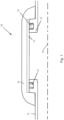
- Fig. 1 shows an existing arrangement for an electrical isolator 10 in which a first pipe 11 (first fluid-carrying member) and second pipe 12 (second fluid carrying member) are spaced apart and electrically isolated from each other by a non-conductive liner tube 13.
- the liner tube 13 is mounted to the ends of each of the pipes 11, 12 by a complex multi-part seal 15 which ensures that the high pressure fluid from within the pipe does not leak.
- Such multi-part seals 15 are expensive.
- the whole structure is over-wound with fibre-reinforced polymer composite 14. Which holds the whole structure together, giving it stability and strength as well as providing a low conductivity path that connects the pipes 11, 12 to allow for static dissipation.
- Fig. 1 shows a cross-section through half of a pipe, with the axis 16 showing the pipe centreline. It will be appreciated that the structure is rotationally symmetric around the centreline 16.
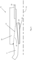
- Fig. 2 shows a first example of this disclosure.
- Fig. 2 only one pipe 11 is shown together with the surrounding structure.
- this is only for convenience and the whole isolator does in fact consist of two such pipes 11, 12 as shown in Fig. 1 , but with the structure shown in Fig. 2 replicated at the other pipe.
- the pipe 11 has an outer surface that is substantially parallel to the central axis 16.
- the pipe 11 has an inner surface that is tapered relative to the central axis 16 such that the thickness of the pipe 11 reduces towards its end.
- the outer surface of the pipe 11 comprises a toothed surface 22 in which is formed a helical thread. It will be appreciated that this could be a single start thread or a multi-start thread and the thread profile could be one of many different profiles.
- the thread is a single start thread and the thread profile is formed so as to produce interspersed teeth 30 and flat seal lands 31.
- the teeth 30 serve to cut into and/or engage with the opposite surface 21 of the composite tube 20 and thereby provide axial load resistance.
- the seal lands 31 provide increased friction between the two parts 11, 20 and therefore when a suitable preload is applied, the added resistance from the seal lands 31 adds significantly to the axial load resistance.
- the composite tube 20 is pre-formed from a hollow tube of fibre-reinforced composite which is formed from fibres (e.g. carbon fibres or glass fibres) disposed in a matrix (e.g. an epoxy resin) with a conductive additive (e.g. carbon black or carbon nanotubes) in the matrix that is used to carefully control the electrical conductivity of the tube 20.
- a matrix e.g. an epoxy resin
- a conductive additive e.g. carbon black or carbon nanotubes
- Fig. 2 In order to bias the pipe 11 and the composite tube 20 together, two compression fittings 23, 24 are shown in Fig. 2 . It will be appreciated that these can both be used together for maximum compression of the joint. However in many applications only one of these compression fittings 23, 24 is required and only one would be used in order to save weight. Both are shown here for convenience.
- the outer compression fitting 23 is a ring mounted on the outer diameter of the composite tube 20 and is designed to have an interference fit therewith, i.e. the inner diameter of the compression fitting 23 is made slightly smaller than the outer diameter of the composite tube 20 such that when the fitting 23 is pressed into position as shown in Fig. 2 , it biases the interface region 21 of composite tube 20 against the toothed surface 22 of pipe 11. This biasing increases the friction between these two surfaces 21, 22, thereby increasing the axial load resistance and effecting a good seal between the pipe 11 and the tube 20.
- the seal lands 31 provide a high contact area parallel to the two surfaces that increases the friction between them.
- the inner compression fitting 24 in this example is a wedge shaped ring which is tapered on its outer surface such that it is wider at the end closest to the end of the pipe 11 and gets narrower away from that end.
- the tapered outer surface of the compression fitting 24 mates with a correspondingly tapered surface on the inner diameter of the pipe 11. These two mating surfaces have the same taper angle.
- the inner compression fitting 24 may not be wedge shaped, but instead be cylindrical like the compression fitting 23.
- the compression fitting 24 may have a thread 25 on its inner diameter that can be used to push or pull the compression fitting 24 into position when required to effect the seal.
- a threaded tool can be inserted in through the pipe 11 (or through the pipe 12), threaded into the thread 25 so as to engage the fitting 24 and can then be used to move the fitting 24 into the desired position. The tool can then be unscrewed and removed, leaving the fitting 24 in place.
- the compression fittings 23, 24 may be formed from metal for high stiffness and strength. However they could alternatively be made of other materials.
- the outer compression fitting 23 could be made from hoop wound (circumferentially wound) fibre-reinforced polymer as this is lighter in weight while still having the required strength to provide the required compression.
- a non-conductive liner 26 is shown overlapping the end of the pipe 11 and lying radially outside the pipe 11.
- the liner 26 is made from a non-conductive material such as PEEK (polyether ether ketone) or glass fibre-reinforced polymer (without any conductive additive in the resin).
- the liner 26 can be used to ensure the electrical separation of the two pipes 11, 12 in accordance with regulations.
- the composite tube 20 can itself ensure the required separation and therefore the liner 26 is not essential.
- a further possible benefit of the liner 26 is that the composite tube 20 could be wound in place onto the pipes 11, 12 and then cured. In such cases the fibre would need a surface to be wound on before curing has taken place.
- the liner 26 provides such a surface across the gap between the two pipes 11, 12.
- the composite tube 20 is pre-formed (and cured) into a hollow tube which is then cut to size and then mated with the pipes 11, 12, there will potentially be no need for the liner 26.
- a sealant 27 is shown at the end of the pipe 11, located radially between the pipe 11 and the composite tube 20.
- the sealant 27 is not essential as an adequate seal is provided by sufficient compression of the toothed surface 22 and the interface region 21. However, the sealant 27 adds little extra cost and weight and provides an extra quality assurance that a good seal will be formed and maintained throughout the life of the product.
- the sealant 27 may be any suitable type of sealant such as those already used in hydraulic or fuel systems.
- the sealant may also act as an adhesive, holding the two parts 11, 20 firmly together.
- the sealant 27 may also, as shown in Fig. 2 , contact and seal against the liner 26 if present.
- Fig. 3 shows a second example olator 10. This example shares many features with the example of Fig. 2 . However, in this example, only an inner compression fitting 24 is shown, i.e. there is no outer compression fitting in this example. Further, the non-conductive liner 26 is not present in this example.
- Fig. 4 shows a third example electrical isolator 10.
- This example also shares many features with the examples of Figs. 2 and 3 .
- the liner 26 is present, but there is no additional sealant added to the joint.
- the main difference is that the toothed surface 22 of the pipe 11 and the interface region 21 of the composite tube 20 are not parallel to the tube axis 16, but rather are tapered at an angle with respect to that axis 16.
- the tapering of this interface has the advantage that the engagement of the toothed surface 22 and the interface region 21 is distributed across the radial thickness of the tube 20 rather than all being at the outer diameter thereof.
- This distribution of the interface ensures that the load is transferred through a greater number of fibres in the tube 20.
- the tube 20 is typically built up from several layers of fibres, each layer lying over the top of the previous layer.
- engaging across a greater thickness of the tube 20 ensures engagement with a greater number of layers and a greater number of fibres, thus distributing the load more evenly through the composite tube and thus reducing the mechanical requirements of the tube 20 (which may in turn allow the tube 20 to be reduced in thickness, thus saving weight).
- Fig. 5 is the same as Fig. 4 except that the wedge shaped inner compression fitting 24 has been replaced with an outer compression fitting 23.
- the compression fitting 23 is shaped in this example to be tapered from a radially thinner end to a radially thicker end.
- the taper of the compression fitting 23 is opposite to that of the interface region 21 and toothed surface 22 such that the thicker end is closer to the end of the pipe 11. This ensures the greatest compression force at the innermost end of the seal where pressure is greatest, while allowing the compression fitting 23 to be thinner at the outermost end of the seal where pressure will be reduced.
- This variation of thickness allows an overall reduction in weight of the compression fitting 23. This benefit also applies to the wedge shaped inner compression fitting 24 described above.
- the outer surface of the composite tube 20 need not be parallel to the axis 16 and can instead have a profile that is optimised for weight, pressure or interference fit on the thread.
- Fig. 6 also shares many features with Fig. 2 .
- the main differences are that no outer compression fitting 23 is provided.
- the wedge shaped inner compression fitting 24 is provided as in Fig. 2 , but the pipe 11 has a profile on its inner surface that is designed to accept the wedge shaped compression fitting 24 such that when it is in the fully installed position, the inner surface of the fitting 24 is flush with the inner surface of the pipe 11. This reduces turbulence in the flow within the pipe.
- the threaded part 25 of the compression fitting 24 extends radially inwardly of the recess in pipe 11 so that the fitting 24 could be pulled by a threaded tool inserted through pipe 11. In other examples the threaded part 25 could also be accommodated in the recess.
- the composite tube 20 in Fig. 5 can be seen to extend over a raised shoulder 35 of the pipe 11, thus holding the pipe 11 securely in place.
- the composite tube 20 must be wound in situ rather than pre-formed as a pre-cured hollow tube that is simply cut down to size.
- a liner 26 (not shown in Fig. 6 ) may be provided in order to provide a supporting surface on which to wind the composite tube 20.
- a sacrificial (e.g. dissolvable) liner may used that may later be removed if desired.
Landscapes
- Engineering & Computer Science (AREA)
- General Engineering & Computer Science (AREA)
- Mechanical Engineering (AREA)
- Shafts, Cranks, Connecting Bars, And Related Bearings (AREA)
Claims (15)
- Elektrischer Isolator (10), umfassend:ein erstes fluidführendes Element (11) und ein zweites fluidführendes Element (12), das von dem ersten fluidführenden Element (11) beabstandet ist;wobei das erste fluidführende Element (11) eine erste gezahnte Oberfläche (22) aufweist und das zweite fluidführende Element (12) eine zweite gezahnte Oberfläche (22) aufweist;wobei der elektrische Isolator (10) ferner umfasst:ein faserverstärktes Polymerrohr (20), das sowohl das erste fluidführende Element (11) als auch das zweite fluidführende Element (12) überlappt und das die erste gezahnte Oberfläche (22) in einem ersten Grenzflächenbereich (21) des faserverstärkten Polymerrohrs (20) berührt und das die zweite gezahnte Oberfläche (22) in einem zweiten Grenzflächenbereich (21) des faserverstärkten Polymerrohrs (20) berührt; und gekennzeichnet durcheine Klemmverschraubung (23, 24), die so angeordnet ist, dass sie den ersten Grenzflächenbereich (21) und die erste gezahnte Oberfläche (22) miteinander vorspannt, indem sie eine Vorlast auf die erste gezahnte Oberfläche (22) und den ersten Grenzflächenbereich (21) bereitstellt.
- Elektrischer Isolator (10) nach Anspruch 1, wobei die Klemmverschraubung (23, 24) eine erste Klemmverschraubung (23, 24) ist und wobei der elektrische Isolator (10) ferner eine zweite Klemmverschraubung (23, 24) umfasst, die so angeordnet ist, dass sie den zweiten Grenzflächenbereich (21) und die zweite gezahnte Oberfläche (22) miteinander vorspannt.
- Elektrischer Isolator (10) nach Anspruch 1 oder 2, wobei die erste gezahnte Oberfläche (22) und/oder die zweite gezahnte Oberfläche (22) mit einem Gewinde versehen ist/sind.
- Elektrischer Isolator (10) nach Anspruch 1, 2 oder 3, wobei die erste gezahnte Oberfläche (22) und der erste Grenzflächenbereich (21) konisch sind; und/oder wobei die zweite gezahnte Oberfläche (22) und der zweite Grenzflächenbereich (21) konisch sind.
- Elektrischer Isolator (10) nach einem der vorstehenden Ansprüche, wobei sich die Klemmverschraubung (24) radial innerhalb der ersten gezahnten Oberfläche (22) befindet.
- Elektrischer Isolator (10) nach Anspruch 5, wobei die Klemmverschraubung (24) ein Hohlzylinder ist, der so angeordnet ist, dass sein Innendurchmesser im installierten Zustand mit dem Innendurchmesser des ersten fluidführenden Elements (11, 12) bündig ist.
- Elektrischer Isolator (10) nach einem der Ansprüche 1 bis 4, wobei sich die Klemmverschraubung (23) radial außerhalb der ersten gezahnten Oberfläche (22) befindet.
- Elektrischer Isolator (10) nach Anspruch 7, wobei die Klemmverschraubung (23) aus in Umfangsrichtung gewickeltem faserverstärktem Polymer gebildet ist.
- Elektrischer Isolator (10) nach einem der vorstehenden Ansprüche, wobei die Klemmverschraubung (23, 24) eine sich verjüngende Oberfläche aufweist, die so angeordnet ist, dass sie mit einer sich verjüngenden Oberfläche des fluidführenden Elements (11, 12) oder des faserverstärkten Polymerrohrs (20) zusammenpasst, sodass eine axiale Bewegung der Klemmverschraubung (23, 24) die Vorspannkraft der ersten gezahnten Oberfläche (22) und des ersten Grenzflächenbereichs (21) verändert.
- Elektrischer Isolator (10) nach einem der vorstehenden Ansprüche, wobei das erste (11) und das zweite (12) fluidführende Element aus Metall sind.
- Elektrischer Isolator (10) nach einem der vorstehenden Ansprüche, ferner umfassend einen nicht-leitfähigen Separator (26), der zwischen dem ersten (11) und dem zweiten (12) fluidführenden Element angeordnet ist.
- Elektrischer Isolator (10) nach einem der vorhergehenden Ansprüche, ferner umfassend eine Dichtungsschicht (27), die zwischen dem ersten (11) und zweiten (12) fluidführenden Element und dem faserverstärkten Polymerrohr (20) angeordnet ist.
- Elektrischer Isolator (10) nach einem der vorstehenden Ansprüche, wobei das faserverstärkte Polymerrohr teilweise elektrisch leitfähig ist.
- Elektrischer Isolator (10) nach Anspruch 13, wobei das faserverstärkte Polymerrohr (20) Fasern umfasst, die in einer Polymermatrix angeordnet sind, und wobei die Polymermatrix ein leitfähiges Additiv umfasst.
- Verfahren zum Bilden eines elektrischen Isolators (10), wobei das Verfahren umfasst:Ineingriffbringen einer ersten gezahnten Oberfläche (22) eines ersten fluidführenden Elements (11) mit einem ersten Grenzflächenbereich (21) eines faserverstärkten Polymerrohrs (20) ;Ineingriffbringen einer zweiten gezahnten Oberfläche (22) eines zweiten fluidführenden Elements (12) mit einem zweiten Grenzflächenbereich (21) des faserverstärkten Polymerrohrs (20); und gekennzeichnet durchAnlegen einer Klemmverschraubung (23, 24), um den ersten Grenzflächenbereich (21) und die erste gezahnte Oberfläche (22) miteinander vorzuspannen, indem eine Vorlast auf die erste gezahnte Oberfläche (22) und den ersten Grenzflächenbereich (21) bereitgestellt wird.
Priority Applications (5)
| Application Number | Priority Date | Filing Date | Title |
|---|---|---|---|
| EP19386021.0A EP3719372B1 (de) | 2019-04-02 | 2019-04-02 | Elektrischer isolator |
| BR102019026499-3A BR102019026499B1 (pt) | 2019-04-02 | 2019-12-12 | Isolador elétrico, e, método para formar um isolador elétrico |
| CA3065243A CA3065243A1 (en) | 2019-04-02 | 2019-12-13 | Electrical isolator |
| CN201911284151.3A CN111795236B (zh) | 2019-04-02 | 2019-12-13 | 电隔离器 |
| US16/717,775 US11264153B2 (en) | 2019-04-02 | 2019-12-17 | Electrical isolator |
Applications Claiming Priority (1)
| Application Number | Priority Date | Filing Date | Title |
|---|---|---|---|
| EP19386021.0A EP3719372B1 (de) | 2019-04-02 | 2019-04-02 | Elektrischer isolator |
Publications (2)
| Publication Number | Publication Date |
|---|---|
| EP3719372A1 EP3719372A1 (de) | 2020-10-07 |
| EP3719372B1 true EP3719372B1 (de) | 2023-06-07 |
Family
ID=66218033
Family Applications (1)
| Application Number | Title | Priority Date | Filing Date |
|---|---|---|---|
| EP19386021.0A Active EP3719372B1 (de) | 2019-04-02 | 2019-04-02 | Elektrischer isolator |
Country Status (4)
| Country | Link |
|---|---|
| US (1) | US11264153B2 (de) |
| EP (1) | EP3719372B1 (de) |
| CN (1) | CN111795236B (de) |
| CA (1) | CA3065243A1 (de) |
Families Citing this family (2)
| Publication number | Priority date | Publication date | Assignee | Title |
|---|---|---|---|---|
| EP3719368B1 (de) * | 2019-04-02 | 2023-01-11 | Crompton Technology Group Limited | Elektrischer isolator und entsprechendes herstellungsverfahren |
| CN115958852B (zh) * | 2022-12-23 | 2025-11-25 | 贵州电网有限责任公司 | 一种纤维搭载纳米粒子填充环氧树脂制备复合材料的方法及应用 |
Family Cites Families (16)
| Publication number | Priority date | Publication date | Assignee | Title |
|---|---|---|---|---|
| US3462175A (en) * | 1965-04-20 | 1969-08-19 | Sonel | Connector for unthreaded pipe,and method of making the same |
| US4099021A (en) * | 1970-04-24 | 1978-07-04 | Amerace Corporation | Method of splicing high voltage shielded cables and splice connector therefor |
| US4011652A (en) * | 1976-04-29 | 1977-03-15 | Psi Products, Inc. | Method for making a pipe coupling |
| US4383131A (en) * | 1978-09-14 | 1983-05-10 | Raychem Limited | Shielded electrical cable joints and terminations and sleeve and method for forming same |
| US4314093A (en) * | 1979-03-29 | 1982-02-02 | International Telephone And Telegraph Corporation | Cable connector |
| US4398754A (en) * | 1980-08-11 | 1983-08-16 | Kerotest Manufacturing Corp. | Electrically insulated pipe coupling and method for making the same |
| US5114190A (en) | 1990-10-16 | 1992-05-19 | Parker Hannifin Corporation | Electrically insulated tube union |
| US5131688A (en) * | 1990-12-28 | 1992-07-21 | Coupling Systems, Inc. | Pipe insulator and method for making same |
| DE602006015937D1 (de) * | 2006-06-21 | 2010-09-16 | Abb Technology Ltd | Vorrichtung zur elektrischen Feldsteuerung |
| CA2657500A1 (en) | 2006-06-22 | 2008-01-03 | Airbus Espana, S.L. | Current-insulating system for fluid systems |
| GB0800538D0 (en) | 2008-01-11 | 2008-02-20 | Crompton Technology Group Ltd | Fuel pipes with controlled resistivity |
| US8956556B2 (en) * | 2008-07-02 | 2015-02-17 | Eaton Corporation | Dielectric isolators |
| WO2011144440A1 (en) * | 2010-05-17 | 2011-11-24 | Parker Hannifin Gmbh | Dielectric fitting assembly |
| US9169029B2 (en) * | 2012-06-08 | 2015-10-27 | The Boeing Company | Conductive coupling assembly |
| CN103307380B (zh) * | 2013-05-15 | 2015-07-01 | 中国科学院等离子体物理研究所 | 一种具备电位隔离功能的低温流体输送管接头 |
| EP3153756B1 (de) | 2015-10-08 | 2020-05-06 | Crompton Technology Group Limited | Elektrischer isolator |
-
2019
- 2019-04-02 EP EP19386021.0A patent/EP3719372B1/de active Active
- 2019-12-13 CA CA3065243A patent/CA3065243A1/en active Pending
- 2019-12-13 CN CN201911284151.3A patent/CN111795236B/zh active Active
- 2019-12-17 US US16/717,775 patent/US11264153B2/en active Active
Also Published As
| Publication number | Publication date |
|---|---|
| CN111795236A (zh) | 2020-10-20 |
| US20200321148A1 (en) | 2020-10-08 |
| CA3065243A1 (en) | 2020-10-02 |
| BR102019026499A2 (pt) | 2020-10-13 |
| EP3719372A1 (de) | 2020-10-07 |
| CN111795236B (zh) | 2023-06-13 |
| US11264153B2 (en) | 2022-03-01 |
Similar Documents
| Publication | Publication Date | Title |
|---|---|---|
| EP3203094B1 (de) | Faserverbund-wellenverbindung | |
| US12169002B2 (en) | Composite shaft | |
| CN1053036C (zh) | 纤维增强复合材料管接头和其组成的复合材料管 | |
| US11466725B2 (en) | Composite shaft | |
| EP3025846B1 (de) | Zusammengesetzter Zug-/Druckstab | |
| US11264153B2 (en) | Electrical isolator | |
| US11525529B2 (en) | Composite tubular structure | |
| EP3719368B1 (de) | Elektrischer isolator und entsprechendes herstellungsverfahren | |
| EP3719369B1 (de) | Elektrischer isolator und verfahren zu dessen herstellung | |
| BR102019026499B1 (pt) | Isolador elétrico, e, método para formar um isolador elétrico | |
| EP0239338B1 (de) | Verbindungsstücke für gewickelte Rohre | |
| EP3859175A1 (de) | Endanschlüsse aus verbundwerkstoff | |
| EP3719370B1 (de) | Elektrischer isolator | |
| EP4450859B1 (de) | Verbundrohrverbinderanordnung |
Legal Events
| Date | Code | Title | Description |
|---|---|---|---|
| PUAI | Public reference made under article 153(3) epc to a published international application that has entered the european phase |
Free format text: ORIGINAL CODE: 0009012 |
|
| STAA | Information on the status of an ep patent application or granted ep patent |
Free format text: STATUS: THE APPLICATION HAS BEEN PUBLISHED |
|
| AK | Designated contracting states |
Kind code of ref document: A1 Designated state(s): AL AT BE BG CH CY CZ DE DK EE ES FI FR GB GR HR HU IE IS IT LI LT LU LV MC MK MT NL NO PL PT RO RS SE SI SK SM TR |
|
| AX | Request for extension of the european patent |
Extension state: BA ME |
|
| STAA | Information on the status of an ep patent application or granted ep patent |
Free format text: STATUS: REQUEST FOR EXAMINATION WAS MADE |
|
| 17P | Request for examination filed |
Effective date: 20210407 |
|
| RBV | Designated contracting states (corrected) |
Designated state(s): AL AT BE BG CH CY CZ DE DK EE ES FI FR GB GR HR HU IE IS IT LI LT LU LV MC MK MT NL NO PL PT RO RS SE SI SK SM TR |
|
| STAA | Information on the status of an ep patent application or granted ep patent |
Free format text: STATUS: EXAMINATION IS IN PROGRESS |
|
| 17Q | First examination report despatched |
Effective date: 20211110 |
|
| GRAP | Despatch of communication of intention to grant a patent |
Free format text: ORIGINAL CODE: EPIDOSNIGR1 |
|
| STAA | Information on the status of an ep patent application or granted ep patent |
Free format text: STATUS: GRANT OF PATENT IS INTENDED |
|
| INTG | Intention to grant announced |
Effective date: 20230103 |
|
| GRAS | Grant fee paid |
Free format text: ORIGINAL CODE: EPIDOSNIGR3 |
|
| GRAA | (expected) grant |
Free format text: ORIGINAL CODE: 0009210 |
|
| STAA | Information on the status of an ep patent application or granted ep patent |
Free format text: STATUS: THE PATENT HAS BEEN GRANTED |
|
| AK | Designated contracting states |
Kind code of ref document: B1 Designated state(s): AL AT BE BG CH CY CZ DE DK EE ES FI FR GB GR HR HU IE IS IT LI LT LU LV MC MK MT NL NO PL PT RO RS SE SI SK SM TR |
|
| REG | Reference to a national code |
Ref country code: GB Ref legal event code: FG4D |
|
| REG | Reference to a national code |
Ref country code: CH Ref legal event code: EP Ref country code: AT Ref legal event code: REF Ref document number: 1576020 Country of ref document: AT Kind code of ref document: T Effective date: 20230615 |
|
| REG | Reference to a national code |
Ref country code: DE Ref legal event code: R096 Ref document number: 602019030002 Country of ref document: DE |
|
| REG | Reference to a national code |
Ref country code: LT Ref legal event code: MG9D |
|
| REG | Reference to a national code |
Ref country code: NL Ref legal event code: MP Effective date: 20230607 |
|
| PG25 | Lapsed in a contracting state [announced via postgrant information from national office to epo] |
Ref country code: SE Free format text: LAPSE BECAUSE OF FAILURE TO SUBMIT A TRANSLATION OF THE DESCRIPTION OR TO PAY THE FEE WITHIN THE PRESCRIBED TIME-LIMIT Effective date: 20230607 Ref country code: NO Free format text: LAPSE BECAUSE OF FAILURE TO SUBMIT A TRANSLATION OF THE DESCRIPTION OR TO PAY THE FEE WITHIN THE PRESCRIBED TIME-LIMIT Effective date: 20230907 Ref country code: ES Free format text: LAPSE BECAUSE OF FAILURE TO SUBMIT A TRANSLATION OF THE DESCRIPTION OR TO PAY THE FEE WITHIN THE PRESCRIBED TIME-LIMIT Effective date: 20230607 |
|
| REG | Reference to a national code |
Ref country code: AT Ref legal event code: MK05 Ref document number: 1576020 Country of ref document: AT Kind code of ref document: T Effective date: 20230607 |
|
| PG25 | Lapsed in a contracting state [announced via postgrant information from national office to epo] |
Ref country code: RS Free format text: LAPSE BECAUSE OF FAILURE TO SUBMIT A TRANSLATION OF THE DESCRIPTION OR TO PAY THE FEE WITHIN THE PRESCRIBED TIME-LIMIT Effective date: 20230607 Ref country code: NL Free format text: LAPSE BECAUSE OF FAILURE TO SUBMIT A TRANSLATION OF THE DESCRIPTION OR TO PAY THE FEE WITHIN THE PRESCRIBED TIME-LIMIT Effective date: 20230607 Ref country code: LV Free format text: LAPSE BECAUSE OF FAILURE TO SUBMIT A TRANSLATION OF THE DESCRIPTION OR TO PAY THE FEE WITHIN THE PRESCRIBED TIME-LIMIT Effective date: 20230607 Ref country code: LT Free format text: LAPSE BECAUSE OF FAILURE TO SUBMIT A TRANSLATION OF THE DESCRIPTION OR TO PAY THE FEE WITHIN THE PRESCRIBED TIME-LIMIT Effective date: 20230607 Ref country code: HR Free format text: LAPSE BECAUSE OF FAILURE TO SUBMIT A TRANSLATION OF THE DESCRIPTION OR TO PAY THE FEE WITHIN THE PRESCRIBED TIME-LIMIT Effective date: 20230607 Ref country code: GR Free format text: LAPSE BECAUSE OF FAILURE TO SUBMIT A TRANSLATION OF THE DESCRIPTION OR TO PAY THE FEE WITHIN THE PRESCRIBED TIME-LIMIT Effective date: 20230908 |
|
| PG25 | Lapsed in a contracting state [announced via postgrant information from national office to epo] |
Ref country code: FI Free format text: LAPSE BECAUSE OF FAILURE TO SUBMIT A TRANSLATION OF THE DESCRIPTION OR TO PAY THE FEE WITHIN THE PRESCRIBED TIME-LIMIT Effective date: 20230607 |
|
| PG25 | Lapsed in a contracting state [announced via postgrant information from national office to epo] |
Ref country code: SK Free format text: LAPSE BECAUSE OF FAILURE TO SUBMIT A TRANSLATION OF THE DESCRIPTION OR TO PAY THE FEE WITHIN THE PRESCRIBED TIME-LIMIT Effective date: 20230607 |
|
| PG25 | Lapsed in a contracting state [announced via postgrant information from national office to epo] |
Ref country code: IS Free format text: LAPSE BECAUSE OF FAILURE TO SUBMIT A TRANSLATION OF THE DESCRIPTION OR TO PAY THE FEE WITHIN THE PRESCRIBED TIME-LIMIT Effective date: 20231007 |
|
| PG25 | Lapsed in a contracting state [announced via postgrant information from national office to epo] |
Ref country code: SM Free format text: LAPSE BECAUSE OF FAILURE TO SUBMIT A TRANSLATION OF THE DESCRIPTION OR TO PAY THE FEE WITHIN THE PRESCRIBED TIME-LIMIT Effective date: 20230607 Ref country code: SK Free format text: LAPSE BECAUSE OF FAILURE TO SUBMIT A TRANSLATION OF THE DESCRIPTION OR TO PAY THE FEE WITHIN THE PRESCRIBED TIME-LIMIT Effective date: 20230607 Ref country code: RO Free format text: LAPSE BECAUSE OF FAILURE TO SUBMIT A TRANSLATION OF THE DESCRIPTION OR TO PAY THE FEE WITHIN THE PRESCRIBED TIME-LIMIT Effective date: 20230607 Ref country code: PT Free format text: LAPSE BECAUSE OF FAILURE TO SUBMIT A TRANSLATION OF THE DESCRIPTION OR TO PAY THE FEE WITHIN THE PRESCRIBED TIME-LIMIT Effective date: 20231009 Ref country code: IS Free format text: LAPSE BECAUSE OF FAILURE TO SUBMIT A TRANSLATION OF THE DESCRIPTION OR TO PAY THE FEE WITHIN THE PRESCRIBED TIME-LIMIT Effective date: 20231007 Ref country code: EE Free format text: LAPSE BECAUSE OF FAILURE TO SUBMIT A TRANSLATION OF THE DESCRIPTION OR TO PAY THE FEE WITHIN THE PRESCRIBED TIME-LIMIT Effective date: 20230607 Ref country code: CZ Free format text: LAPSE BECAUSE OF FAILURE TO SUBMIT A TRANSLATION OF THE DESCRIPTION OR TO PAY THE FEE WITHIN THE PRESCRIBED TIME-LIMIT Effective date: 20230607 Ref country code: AT Free format text: LAPSE BECAUSE OF FAILURE TO SUBMIT A TRANSLATION OF THE DESCRIPTION OR TO PAY THE FEE WITHIN THE PRESCRIBED TIME-LIMIT Effective date: 20230607 |
|
| PG25 | Lapsed in a contracting state [announced via postgrant information from national office to epo] |
Ref country code: PL Free format text: LAPSE BECAUSE OF FAILURE TO SUBMIT A TRANSLATION OF THE DESCRIPTION OR TO PAY THE FEE WITHIN THE PRESCRIBED TIME-LIMIT Effective date: 20230607 |
|
| REG | Reference to a national code |
Ref country code: DE Ref legal event code: R097 Ref document number: 602019030002 Country of ref document: DE |
|
| PLBE | No opposition filed within time limit |
Free format text: ORIGINAL CODE: 0009261 |
|
| STAA | Information on the status of an ep patent application or granted ep patent |
Free format text: STATUS: NO OPPOSITION FILED WITHIN TIME LIMIT |
|
| PG25 | Lapsed in a contracting state [announced via postgrant information from national office to epo] |
Ref country code: DK Free format text: LAPSE BECAUSE OF FAILURE TO SUBMIT A TRANSLATION OF THE DESCRIPTION OR TO PAY THE FEE WITHIN THE PRESCRIBED TIME-LIMIT Effective date: 20230607 |
|
| PG25 | Lapsed in a contracting state [announced via postgrant information from national office to epo] |
Ref country code: SI Free format text: LAPSE BECAUSE OF FAILURE TO SUBMIT A TRANSLATION OF THE DESCRIPTION OR TO PAY THE FEE WITHIN THE PRESCRIBED TIME-LIMIT Effective date: 20230607 |
|
| 26N | No opposition filed |
Effective date: 20240308 |
|
| PG25 | Lapsed in a contracting state [announced via postgrant information from national office to epo] |
Ref country code: SI Free format text: LAPSE BECAUSE OF FAILURE TO SUBMIT A TRANSLATION OF THE DESCRIPTION OR TO PAY THE FEE WITHIN THE PRESCRIBED TIME-LIMIT Effective date: 20230607 |
|
| PG25 | Lapsed in a contracting state [announced via postgrant information from national office to epo] |
Ref country code: BG Free format text: LAPSE BECAUSE OF FAILURE TO SUBMIT A TRANSLATION OF THE DESCRIPTION OR TO PAY THE FEE WITHIN THE PRESCRIBED TIME-LIMIT Effective date: 20230607 |
|
| PG25 | Lapsed in a contracting state [announced via postgrant information from national office to epo] |
Ref country code: MC Free format text: LAPSE BECAUSE OF FAILURE TO SUBMIT A TRANSLATION OF THE DESCRIPTION OR TO PAY THE FEE WITHIN THE PRESCRIBED TIME-LIMIT Effective date: 20230607 |
|
| PG25 | Lapsed in a contracting state [announced via postgrant information from national office to epo] |
Ref country code: MC Free format text: LAPSE BECAUSE OF FAILURE TO SUBMIT A TRANSLATION OF THE DESCRIPTION OR TO PAY THE FEE WITHIN THE PRESCRIBED TIME-LIMIT Effective date: 20230607 Ref country code: BG Free format text: LAPSE BECAUSE OF FAILURE TO SUBMIT A TRANSLATION OF THE DESCRIPTION OR TO PAY THE FEE WITHIN THE PRESCRIBED TIME-LIMIT Effective date: 20230607 |
|
| REG | Reference to a national code |
Ref country code: CH Ref legal event code: PL |
|
| PG25 | Lapsed in a contracting state [announced via postgrant information from national office to epo] |
Ref country code: LU Free format text: LAPSE BECAUSE OF NON-PAYMENT OF DUE FEES Effective date: 20240402 |
|
| REG | Reference to a national code |
Ref country code: BE Ref legal event code: MM Effective date: 20240430 |
|
| PG25 | Lapsed in a contracting state [announced via postgrant information from national office to epo] |
Ref country code: LU Free format text: LAPSE BECAUSE OF NON-PAYMENT OF DUE FEES Effective date: 20240402 |
|
| PG25 | Lapsed in a contracting state [announced via postgrant information from national office to epo] |
Ref country code: BE Free format text: LAPSE BECAUSE OF NON-PAYMENT OF DUE FEES Effective date: 20240430 |
|
| PG25 | Lapsed in a contracting state [announced via postgrant information from national office to epo] |
Ref country code: BE Free format text: LAPSE BECAUSE OF NON-PAYMENT OF DUE FEES Effective date: 20240430 Ref country code: CH Free format text: LAPSE BECAUSE OF NON-PAYMENT OF DUE FEES Effective date: 20240430 |
|
| PG25 | Lapsed in a contracting state [announced via postgrant information from national office to epo] |
Ref country code: IE Free format text: LAPSE BECAUSE OF NON-PAYMENT OF DUE FEES Effective date: 20240402 |
|
| PGFP | Annual fee paid to national office [announced via postgrant information from national office to epo] |
Ref country code: FR Payment date: 20250319 Year of fee payment: 7 |
|
| PGFP | Annual fee paid to national office [announced via postgrant information from national office to epo] |
Ref country code: IT Payment date: 20250319 Year of fee payment: 7 |
|
| PGFP | Annual fee paid to national office [announced via postgrant information from national office to epo] |
Ref country code: DE Payment date: 20250319 Year of fee payment: 7 |
|
| PG25 | Lapsed in a contracting state [announced via postgrant information from national office to epo] |
Ref country code: CY Free format text: LAPSE BECAUSE OF FAILURE TO SUBMIT A TRANSLATION OF THE DESCRIPTION OR TO PAY THE FEE WITHIN THE PRESCRIBED TIME-LIMIT; INVALID AB INITIO Effective date: 20190402 |
|
| PG25 | Lapsed in a contracting state [announced via postgrant information from national office to epo] |
Ref country code: HU Free format text: LAPSE BECAUSE OF FAILURE TO SUBMIT A TRANSLATION OF THE DESCRIPTION OR TO PAY THE FEE WITHIN THE PRESCRIBED TIME-LIMIT; INVALID AB INITIO Effective date: 20190402 |
|
| PG25 | Lapsed in a contracting state [announced via postgrant information from national office to epo] |
Ref country code: TR Free format text: LAPSE BECAUSE OF FAILURE TO SUBMIT A TRANSLATION OF THE DESCRIPTION OR TO PAY THE FEE WITHIN THE PRESCRIBED TIME-LIMIT Effective date: 20230607 |
|
| PGFP | Annual fee paid to national office [announced via postgrant information from national office to epo] |
Ref country code: GB Payment date: 20260327 Year of fee payment: 8 |