EP3719385A1 - Bougie électrique - Google Patents
Bougie électrique Download PDFInfo
- Publication number
- EP3719385A1 EP3719385A1 EP20167484.3A EP20167484A EP3719385A1 EP 3719385 A1 EP3719385 A1 EP 3719385A1 EP 20167484 A EP20167484 A EP 20167484A EP 3719385 A1 EP3719385 A1 EP 3719385A1
- Authority
- EP
- European Patent Office
- Prior art keywords
- area
- shaft
- electric candle
- lighting
- lamp
- Prior art date
- Legal status (The legal status is an assumption and is not a legal conclusion. Google has not performed a legal analysis and makes no representation as to the accuracy of the status listed.)
- Granted
Links
Images
Classifications
-
- F—MECHANICAL ENGINEERING; LIGHTING; HEATING; WEAPONS; BLASTING
- F21—LIGHTING
- F21V—FUNCTIONAL FEATURES OR DETAILS OF LIGHTING DEVICES OR SYSTEMS THEREOF; STRUCTURAL COMBINATIONS OF LIGHTING DEVICES WITH OTHER ARTICLES, NOT OTHERWISE PROVIDED FOR
- F21V17/00—Fastening of component parts of lighting devices, e.g. shades, globes, refractors, reflectors, filters, screens, grids or protective cages
- F21V17/002—Fastening of component parts of lighting devices, e.g. shades, globes, refractors, reflectors, filters, screens, grids or protective cages with provision for interchangeability, i.e. component parts being especially adapted to be replaced by another part with the same or a different function
-
- F—MECHANICAL ENGINEERING; LIGHTING; HEATING; WEAPONS; BLASTING
- F21—LIGHTING
- F21K—NON-ELECTRIC LIGHT SOURCES USING LUMINESCENCE; LIGHT SOURCES USING ELECTROCHEMILUMINESCENCE; LIGHT SOURCES USING CHARGES OF COMBUSTIBLE MATERIAL; LIGHT SOURCES USING SEMICONDUCTOR DEVICES AS LIGHT-GENERATING ELEMENTS; LIGHT SOURCES NOT OTHERWISE PROVIDED FOR
- F21K9/00—Light sources using semiconductor devices as light-generating elements, e.g. using light-emitting diodes [LED] or lasers
- F21K9/20—Light sources comprising attachment means
- F21K9/23—Retrofit light sources for lighting devices with a single fitting for each light source, e.g. for substitution of incandescent lamps with bayonet or threaded fittings
- F21K9/232—Retrofit light sources for lighting devices with a single fitting for each light source, e.g. for substitution of incandescent lamps with bayonet or threaded fittings specially adapted for generating an essentially omnidirectional light distribution, e.g. with a glass bulb
-
- F—MECHANICAL ENGINEERING; LIGHTING; HEATING; WEAPONS; BLASTING
- F21—LIGHTING
- F21K—NON-ELECTRIC LIGHT SOURCES USING LUMINESCENCE; LIGHT SOURCES USING ELECTROCHEMILUMINESCENCE; LIGHT SOURCES USING CHARGES OF COMBUSTIBLE MATERIAL; LIGHT SOURCES USING SEMICONDUCTOR DEVICES AS LIGHT-GENERATING ELEMENTS; LIGHT SOURCES NOT OTHERWISE PROVIDED FOR
- F21K9/00—Light sources using semiconductor devices as light-generating elements, e.g. using light-emitting diodes [LED] or lasers
- F21K9/20—Light sources comprising attachment means
- F21K9/23—Retrofit light sources for lighting devices with a single fitting for each light source, e.g. for substitution of incandescent lamps with bayonet or threaded fittings
- F21K9/237—Details of housings or cases, i.e. the parts between the light-generating element and the bases; Arrangement of components within housings or cases
-
- F—MECHANICAL ENGINEERING; LIGHTING; HEATING; WEAPONS; BLASTING
- F21—LIGHTING
- F21V—FUNCTIONAL FEATURES OR DETAILS OF LIGHTING DEVICES OR SYSTEMS THEREOF; STRUCTURAL COMBINATIONS OF LIGHTING DEVICES WITH OTHER ARTICLES, NOT OTHERWISE PROVIDED FOR
- F21V29/00—Protecting lighting devices from thermal damage; Cooling or heating arrangements specially adapted for lighting devices or systems
- F21V29/50—Cooling arrangements
- F21V29/502—Cooling arrangements characterised by the adaptation for cooling of specific components
- F21V29/503—Cooling arrangements characterised by the adaptation for cooling of specific components of light sources
-
- F—MECHANICAL ENGINEERING; LIGHTING; HEATING; WEAPONS; BLASTING
- F21—LIGHTING
- F21V—FUNCTIONAL FEATURES OR DETAILS OF LIGHTING DEVICES OR SYSTEMS THEREOF; STRUCTURAL COMBINATIONS OF LIGHTING DEVICES WITH OTHER ARTICLES, NOT OTHERWISE PROVIDED FOR
- F21V29/00—Protecting lighting devices from thermal damage; Cooling or heating arrangements specially adapted for lighting devices or systems
- F21V29/50—Cooling arrangements
- F21V29/70—Cooling arrangements characterised by passive heat-dissipating elements, e.g. heat-sinks
-
- F—MECHANICAL ENGINEERING; LIGHTING; HEATING; WEAPONS; BLASTING
- F21—LIGHTING
- F21S—NON-PORTABLE LIGHTING DEVICES; SYSTEMS THEREOF; VEHICLE LIGHTING DEVICES SPECIALLY ADAPTED FOR VEHICLE EXTERIORS
- F21S4/00—Lighting devices or systems using a string or strip of light sources
- F21S4/10—Lighting devices or systems using a string or strip of light sources with light sources attached to loose electric cables, e.g. Christmas tree lights
-
- F—MECHANICAL ENGINEERING; LIGHTING; HEATING; WEAPONS; BLASTING
- F21—LIGHTING
- F21W—INDEXING SCHEME ASSOCIATED WITH SUBCLASSES F21K, F21L, F21S and F21V, RELATING TO USES OR APPLICATIONS OF LIGHTING DEVICES OR SYSTEMS
- F21W2121/00—Use or application of lighting devices or systems for decorative purposes, not provided for in codes F21W2102/00 – F21W2107/00
-
- F—MECHANICAL ENGINEERING; LIGHTING; HEATING; WEAPONS; BLASTING
- F21—LIGHTING
- F21Y—INDEXING SCHEME ASSOCIATED WITH SUBCLASSES F21K, F21L, F21S and F21V, RELATING TO THE FORM OR THE KIND OF THE LIGHT SOURCES OR OF THE COLOUR OF THE LIGHT EMITTED
- F21Y2107/00—Light sources with three-dimensionally disposed light-generating elements
- F21Y2107/30—Light sources with three-dimensionally disposed light-generating elements on the outer surface of cylindrical surfaces, e.g. rod-shaped supports having a circular or a polygonal cross section
-
- F—MECHANICAL ENGINEERING; LIGHTING; HEATING; WEAPONS; BLASTING
- F21—LIGHTING
- F21Y—INDEXING SCHEME ASSOCIATED WITH SUBCLASSES F21K, F21L, F21S and F21V, RELATING TO THE FORM OR THE KIND OF THE LIGHT SOURCES OR OF THE COLOUR OF THE LIGHT EMITTED
- F21Y2107/00—Light sources with three-dimensionally disposed light-generating elements
- F21Y2107/40—Light sources with three-dimensionally disposed light-generating elements on the sides of polyhedrons, e.g. cubes or pyramids
-
- F—MECHANICAL ENGINEERING; LIGHTING; HEATING; WEAPONS; BLASTING
- F21—LIGHTING
- F21Y—INDEXING SCHEME ASSOCIATED WITH SUBCLASSES F21K, F21L, F21S and F21V, RELATING TO THE FORM OR THE KIND OF THE LIGHT SOURCES OR OF THE COLOUR OF THE LIGHT EMITTED
- F21Y2115/00—Light-generating elements of semiconductor light sources
- F21Y2115/10—Light-emitting diodes [LED]
Definitions
- the invention relates to an electric candle which is formed from a lamp base and a cylindrical lamp body.
- the cylindrical lamp body is oriented vertically and determines the appearance of a candle, which lights up at its upper end and merges at the lower end into a lamp base for receiving and holding the electric candle.
- Such electric candles can be used in a chain of lights, which can be generally used, for example, for festive lighting of Christmas trees or decorative objects.
- the electric candles are preferably used to illuminate star-shaped lampshades and decorative objects.
- an electric candle with an on and off function emerges.
- a non-contact proximity switch is provided to switch the candle on or off.
- the candle body has a cylindrical shape which has a flame-like configuration at its upper end in order to produce the character of a candle-like lighting.
- the electric candle has one Flame-shaped transparent luminous body at the upper end of the cylindrical hollow body, in which a lighting device with an LED and a battery is housed as an energy store.
- the electric candles according to the prior art have various disadvantages, depending on their design. Often the light sources used, which are mainly based on LED lighting technology, cannot be used optimally in terms of their electrical connection values. In addition, because of their weight, the electrical energy storage devices, the batteries and accumulators, lead to a restriction in the use of the electrical candles.
- the object of the invention is thus to provide an electric candle which can be used in commercially available light chains and with common electrical connection values and which, in addition, can use the advantages of using LED lighting technology.
- the advantages of LED lighting technology are seen in particular in the fact that the lamps get by with very little electrical energy and, moreover, are very light thanks to the use of electronic components.
- LEDs have a very long service life with a correspondingly high number of switching operations and high energy efficiency.
- an electric candle which is essentially composed of a lamp base and a cylindrical lamp body.
- the lamp body consists of an at least partially transparent outer hollow-cylindrical lamp envelope, which is received on one side by the lamp base and on the other distal side has a light-emitting end region.
- the lamp body comprises an inner shaft extending essentially over the length of the lamp envelope, the shaft having an extension area and, at the end, a lighting area with lighting means.
- the light area of the shaft is arranged in the end area of the lamp envelope, which creates the candle-like appearance of a cylindrical body that lights up on one side.
- the shaft is made from a solid material, since the shaft serves as a heat sink for absorbing heat from the illuminants.
- the shaft is in thermally conductive contact with the lamp base in order to dissipate part of the heat via the lamp base to the lamp socket.
- the appearance of the candle is created in particular by the arrangement and concentration of the luminous area at an upper end of the usually vertically arranged cylindrical candle, whereas at the other lower end the non-luminous lamp base is designed to be received in a corresponding lamp socket.
- the shaft in the interior of the candle body is particularly advantageously designed as a circular cylinder in its extension area and as a cuboid in the lighting area, the cuboid having two square end faces. With a square end face, the cuboid merges into the extension area at the end and the other end face forms the distal boundary of the shaft, which is equipped with the illuminants as a light area.
- the lighting means are preferably uniform on the side surfaces of the cuboid distributed and also arranged on the distal end face of the luminous area of the shaft.
- Two lighting means are particularly preferably arranged on each side face of the cuboid and on the distal end face.
- the luminous area is designed to be shorter than the extension area, so that the luminous effect arises in the upper area at the end, where in conventional candles the flame is designed with its luminous effect.
- the shaft with the luminous area for receiving the luminous means is advantageously made in one piece and made of aluminum or plastic.
- the one-piece design of the shaft achieves good heat absorption and dissipation from the illuminants, which are arranged on the surface of the luminous area of the shaft and are in thermal contact therewith.
- the shaft is designed in two parts, the shaft having a core made of aluminum which is overmolded with plastic.
- the aluminum is preferably not encapsulated by plastic, so that the lighting means are applied to the aluminum core and are in contact with it in a correspondingly thermally conductive manner to dissipate the heat.
- the lighting means are particularly preferably designed as LEDs, which are glued onto the lighting area of the shaft.
- the use of LEDs represent a particularly energy-efficient light source for the electric candle and the gluing of the LEDs on the shaft is an arrangement and fixing of the illuminants in a lamp that is advantageous in terms of production technology, which also leads to good thermal contact.
- At least one feed groove is formed in the extension area of the shaft for bringing electrical lines from the lamp base to the electrical lighting means, which are located, as indicated, in the light area at the opposite end of the shaft and must be electrically contacted from the lamp base.
- the end area of the lamp envelope opposite the lamp base is rounded and closed at the end, so that the parts of the lamp carrying electrical current are protected from external influences such as moisture and dust.
- the luminous area with the luminous means are surrounded in the longitudinal extension by a transparent fixing layer which surrounds the luminous means in a form-fitting manner and holds it to the luminous area.
- the extension area is also advantageously surrounded in the longitudinal direction by a decorative fixing layer in order to ensure the mechanical strength of the entire shaft and, in addition, the decorative fixing layer provides the possibility of an attractive aesthetic design as a side effect.
- the fixing layers the transparent fixing layer, which of course has to let the light generated by the lighting means through to the outside in the lighting area
- the decorative fixing layer is designed as a shrink tube.
- the lighting means on the distal end face of the lighting area of the shaft are designed with only 70% of the luminous flux of the lighting means on the side surfaces of the lighting area.
- the electric candle is operated with a voltage of 6.0 volts to 6.3 volts and an output of 0.5 watt to 0.6 watt and has a luminous flux of 50 lumens to 70 lumens.
- the lamp envelope is preferably made of polycarbonate, the lamp envelope particularly preferably being clear in the light area of the shaft and having a frosted look over the extension area of the shaft.
- the lamp base is preferably designed as a so-called E10 base, so that the electric candle can be used in conventional lamp sockets for light chains and the like.
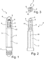
- FIG. 1 an electric candle 1 is shown in a side view.
- the electric candle 1 consists essentially of a lamp body 3 and a lamp base 2 on which the lamp body 3 is placed and connected to it.
- a base of the type E10 is designed as the lamp base 2.
- the lamp body 3 is enclosed on the outside by the lamp envelope 4, which is designed as a hollow cylinder.
- the lamp envelope is designed to be transparent at least in the area of the lighting means 9 in order to emit the generated light to the outside.
- the lamp envelope 4 is made of polycarbonate in the embodiment shown.
- the lamp envelope 4 is connected on one side to the lamp base 2 and on the other side has an end region 6 which is rounded and closed and thus delimits the electrical candle 1 at the top.
- a shaft 5 extending essentially over the entire length of the lamp envelope 4 is arranged coaxially to the lamp envelope 4, which shaft can be functionally divided into two areas.
- the area of the shaft 5 from the lamp base 2, or placed on the lamp base 2, upwards is referred to as the extension area 7, which then merges into the lighting area 8 at the end.
- the luminous area 8 of the shaft is arranged in the end area 6 of the lamp envelope 4.
- the lighting means 9 are arranged in the luminous area 8 in such a way that the light is emitted outwards through the lamp envelope 4, whereby, depending on the specifics of the LED lighting means 9 used, radiation not only in the radial direction but also obliquely upwards and downwards he follows.
- the transparent or at least opaque lamp envelope 4 allows the decorative fixing layer 12, which surrounds the extension region 7 of the shaft 5, to shine through.
- Fig. 2 the shaft 5 of the electric candle 1 is shown separately in the side view.
- the shaft 5 is subdivided into the extension region 7 and the luminous region 8, the luminous region 8 generally being designed to be smaller in axial extension than the extension region 7.
- the luminous area 8 is used to accommodate the luminous means 9 and it is shown in the illustration that the luminous area 8 in the area of the luminous means 9 is surrounded by a layer shown in dotted lines, the transparent fixing layer 11.
- the transparent fixing layer 11 surrounds the lighting means 9 and holds them form-fittingly on the lighting area 8 of the shaft 5.
- the lighting means 9 are designed as LEDs, preferably glued onto the shaft 5 in the lighting area 8.
- the extension region 7 is surrounded by a decorative fixing layer 12 which, in addition to its function of decorative and aesthetic design, also enables the electrical connection lines to be fixed.
- the electrical connection lines (not shown) in the extension area 7 of the shaft 5 are laid in a feed groove 10 and serve to supply the lighting means 9 with electrical energy from the lamp base 2.
- the shaft 5 is received and held on one side by the lamp base 2 and the electrical connections, guided in the feed groove 10, extend from the lamp base 2 over the extension area 7 to the lighting area 8, where the lighting means 9 are in contact with the lines.
- the decorative fixing layer 12 envelops the shaft 5 in the extension region 7 and thus stabilizes the position of the electrical lines in the feed groove 10.
- the shaft 5 in the extension region 7 is preferably designed as a circular cylinder made of solid material.
- the shaft 5 is produced from plastic in an injection molding process, particularly preferably and inexpensively.
- the lighting area 8 is designed in a special way to accommodate the lighting means 9.
- a flat surface is to be provided particularly favorably for thermal contacting, with which the LEDs as lighting means 9 can be connected flatly. This serves the maximum possible heat dissipation from the LEDs into the shaft 5.
- the design according to Fig. 2 is a plan view of the distal end face of the shaft 5 according to Fig. 3 shown.
- the representation according to Fig. 3 shows the execution of the luminous area 8 in cross section as a square.
- other shapes of the polygon as pentagons or hexagons can advantageously be designed. It is decisive in each case that the lighting means 9 are connected to the lighting area in a heat-conducting manner over a large area.
- the shaft 5 is designed as a heat sink, which in the luminous area 8 with appropriate thermal contact with the luminous means 9 absorbs and dissipates the waste heat of the lighting means 9 in order to then partially radiate it via the extension area 7 or to transfer it to the lamp base 2 and dissipate it by means of heat conduction and heat transfer.
- a very efficient embodiment consists in the fact that the shaft 5 is made of aluminum, which realizes excellent heat conduction.
- the shaft is alternatively made of an aluminum core, which can be contacted directly with the lighting means 9 in the lighting area 8.
- the extension area 7 is encapsulated with a plastic.
- the solid material of the shaft 5 itself already absorbs a large part of the heat and distributes it within the shaft, so that local overheating in the area of the lighting means 9 cannot occur.
Landscapes
- Engineering & Computer Science (AREA)
- General Engineering & Computer Science (AREA)
- Physics & Mathematics (AREA)
- Microelectronics & Electronic Packaging (AREA)
- Optics & Photonics (AREA)
- Non-Portable Lighting Devices Or Systems Thereof (AREA)
Applications Claiming Priority (1)
| Application Number | Priority Date | Filing Date | Title |
|---|---|---|---|
| DE202019101941.7U DE202019101941U1 (de) | 2019-04-04 | 2019-04-04 | Elektrische Kerze |
Publications (2)
| Publication Number | Publication Date |
|---|---|
| EP3719385A1 true EP3719385A1 (fr) | 2020-10-07 |
| EP3719385B1 EP3719385B1 (fr) | 2022-04-06 |
Family
ID=66335922
Family Applications (1)
| Application Number | Title | Priority Date | Filing Date |
|---|---|---|---|
| EP20167484.3A Active EP3719385B1 (fr) | 2019-04-04 | 2020-04-01 | Bougie électrique |
Country Status (3)
| Country | Link |
|---|---|
| EP (1) | EP3719385B1 (fr) |
| DE (1) | DE202019101941U1 (fr) |
| DK (1) | DK3719385T3 (fr) |
Citations (7)
| Publication number | Priority date | Publication date | Assignee | Title |
|---|---|---|---|---|
| DE20306723U1 (de) | 2003-04-30 | 2003-07-03 | Kuntze, Jan W., 24939 Flensburg | LED-Kerze mit Batterie-/Akku-Betrieb |
| DE202005018998U1 (de) | 2005-12-05 | 2006-02-09 | Bensch, Marcus | Elektrische Kerze mit Ein-/Ausschaltfunktion |
| DE202006005111U1 (de) | 2006-02-09 | 2006-06-01 | Hsu, Wan-Chang, Chung-Li | Elektrische Kerze mit induktivem Ladegerät |
| US20100177522A1 (en) * | 2009-01-15 | 2010-07-15 | Yeh-Chiang Technology Corp. | Led lamp |
| EP2386790A2 (fr) * | 2010-05-12 | 2011-11-16 | LG Innotek Co., Ltd | Module de dispositif électroluminescent |
| CN103527964A (zh) * | 2013-10-31 | 2014-01-22 | 深圳市中电照明股份有限公司 | 一种实心led灯泡 |
| US20150285487A1 (en) * | 2012-10-26 | 2015-10-08 | Jerry Kochanski | Light bulb, a light bulb holder, and a combination of a light bulb and a light bulb holder |
-
2019
- 2019-04-04 DE DE202019101941.7U patent/DE202019101941U1/de active Active
-
2020
- 2020-04-01 DK DK20167484.3T patent/DK3719385T3/da active
- 2020-04-01 EP EP20167484.3A patent/EP3719385B1/fr active Active
Patent Citations (7)
| Publication number | Priority date | Publication date | Assignee | Title |
|---|---|---|---|---|
| DE20306723U1 (de) | 2003-04-30 | 2003-07-03 | Kuntze, Jan W., 24939 Flensburg | LED-Kerze mit Batterie-/Akku-Betrieb |
| DE202005018998U1 (de) | 2005-12-05 | 2006-02-09 | Bensch, Marcus | Elektrische Kerze mit Ein-/Ausschaltfunktion |
| DE202006005111U1 (de) | 2006-02-09 | 2006-06-01 | Hsu, Wan-Chang, Chung-Li | Elektrische Kerze mit induktivem Ladegerät |
| US20100177522A1 (en) * | 2009-01-15 | 2010-07-15 | Yeh-Chiang Technology Corp. | Led lamp |
| EP2386790A2 (fr) * | 2010-05-12 | 2011-11-16 | LG Innotek Co., Ltd | Module de dispositif électroluminescent |
| US20150285487A1 (en) * | 2012-10-26 | 2015-10-08 | Jerry Kochanski | Light bulb, a light bulb holder, and a combination of a light bulb and a light bulb holder |
| CN103527964A (zh) * | 2013-10-31 | 2014-01-22 | 深圳市中电照明股份有限公司 | 一种实心led灯泡 |
Non-Patent Citations (1)
| Title |
|---|
| ANONYMOUS: "Wayback Machine", 18 January 2019 (2019-01-18), XP055705321, Retrieved from the Internet <URL:https://web.archive.org/web/20190118134155/https://shop.herrnhuter-sterne.de/> [retrieved on 20200616] * |
Also Published As
| Publication number | Publication date |
|---|---|
| EP3719385B1 (fr) | 2022-04-06 |
| DE202019101941U1 (de) | 2019-04-10 |
| DK3719385T3 (da) | 2022-07-11 |
Similar Documents
| Publication | Publication Date | Title |
|---|---|---|
| DE102006045157B4 (de) | Handwerkzeugmaschine | |
| EP2405179B1 (fr) | Lampe de poche | |
| DE202004013773U1 (de) | Lampe | |
| WO2002002989A1 (fr) | Lampe, en particulier lampe de salon, de bureau ou de poche | |
| DE102009006185A1 (de) | Leuchtmittel | |
| EP1285196A1 (fr) | Lampe pour habitation, notamment lampe de table ou lampadaire | |
| EP2171351A1 (fr) | Dispositif d'éclairage | |
| DE20021934U1 (de) | Lampe, insbesondere Wohnraum-, Tisch- oder Taschenlampe | |
| DE20206201U1 (de) | Tragbare LED-Lampe | |
| EP2171352B1 (fr) | Ampoule | |
| WO2009021496A2 (fr) | Moyen d'éclairage à del en forme de lampe à incandescence | |
| EP3719385B1 (fr) | Bougie électrique | |
| WO2011120862A1 (fr) | Lampe à del comme substitut d'ampoule à incandescence | |
| DE29514090U1 (de) | Gehäuselose Rettungszeichenleuchte | |
| EP1510447B3 (fr) | Phare de bicyclette | |
| EP1114962B1 (fr) | Lampe, notamment pour espace d'habitation, lampe de table ou lampe de poche | |
| DE202011103740U1 (de) | Lichterkette mit LED-Beleuchtung | |
| DE9209490U1 (de) | Beleuchtungseinrichtung für ein Blumenaquarium | |
| DE9417300U1 (de) | Signalleuchte, insbesondere Baustellenleuchte, Bakenleuchte o.dgl. | |
| WO2007076736A1 (fr) | Lampe | |
| DE202020100248U1 (de) | Beleuchtungsmodul, umfassend elektrolumineszente Dioden | |
| DE102011016763B3 (de) | Beleuchtungseinrichtung, Leuchtkörperhalter und Leuchtkörper dafür | |
| DE20115131U1 (de) | Leicht austauschbares, energiesparendes und umweltfreundliches Leuchtmittel | |
| DE20016174U1 (de) | Taschenlampe | |
| DE19945782C1 (de) | Taschenleuchte |
Legal Events
| Date | Code | Title | Description |
|---|---|---|---|
| PUAI | Public reference made under article 153(3) epc to a published international application that has entered the european phase |
Free format text: ORIGINAL CODE: 0009012 |
|
| STAA | Information on the status of an ep patent application or granted ep patent |
Free format text: STATUS: THE APPLICATION HAS BEEN PUBLISHED |
|
| AK | Designated contracting states |
Kind code of ref document: A1 Designated state(s): AL AT BE BG CH CY CZ DE DK EE ES FI FR GB GR HR HU IE IS IT LI LT LU LV MC MK MT NL NO PL PT RO RS SE SI SK SM TR |
|
| AX | Request for extension of the european patent |
Extension state: BA ME |
|
| STAA | Information on the status of an ep patent application or granted ep patent |
Free format text: STATUS: REQUEST FOR EXAMINATION WAS MADE |
|
| 17P | Request for examination filed |
Effective date: 20210401 |
|
| RBV | Designated contracting states (corrected) |
Designated state(s): AL AT BE BG CH CY CZ DE DK EE ES FI FR GB GR HR HU IE IS IT LI LT LU LV MC MK MT NL NO PL PT RO RS SE SI SK SM TR |
|
| STAA | Information on the status of an ep patent application or granted ep patent |
Free format text: STATUS: EXAMINATION IS IN PROGRESS |
|
| 17Q | First examination report despatched |
Effective date: 20210706 |
|
| GRAP | Despatch of communication of intention to grant a patent |
Free format text: ORIGINAL CODE: EPIDOSNIGR1 |
|
| STAA | Information on the status of an ep patent application or granted ep patent |
Free format text: STATUS: GRANT OF PATENT IS INTENDED |
|
| RIC1 | Information provided on ipc code assigned before grant |
Ipc: F21Y 115/10 20160101ALN20210924BHEP Ipc: F21Y 107/40 20160101ALN20210924BHEP Ipc: F21Y 107/30 20160101ALN20210924BHEP Ipc: F21S 4/10 20160101ALN20210924BHEP Ipc: F21V 29/503 20150101ALI20210924BHEP Ipc: F21V 29/70 20150101ALI20210924BHEP Ipc: F21K 9/237 20160101ALI20210924BHEP Ipc: F21K 9/232 20160101AFI20210924BHEP |
|
| RIC1 | Information provided on ipc code assigned before grant |
Ipc: F21Y 115/10 20160101ALN20211008BHEP Ipc: F21Y 107/40 20160101ALN20211008BHEP Ipc: F21Y 107/30 20160101ALN20211008BHEP Ipc: F21S 4/10 20160101ALN20211008BHEP Ipc: F21V 29/503 20150101ALI20211008BHEP Ipc: F21V 29/70 20150101ALI20211008BHEP Ipc: F21K 9/237 20160101ALI20211008BHEP Ipc: F21K 9/232 20160101AFI20211008BHEP |
|
| INTG | Intention to grant announced |
Effective date: 20211029 |
|
| GRAS | Grant fee paid |
Free format text: ORIGINAL CODE: EPIDOSNIGR3 |
|
| GRAA | (expected) grant |
Free format text: ORIGINAL CODE: 0009210 |
|
| STAA | Information on the status of an ep patent application or granted ep patent |
Free format text: STATUS: THE PATENT HAS BEEN GRANTED |
|
| AK | Designated contracting states |
Kind code of ref document: B1 Designated state(s): AL AT BE BG CH CY CZ DE DK EE ES FI FR GB GR HR HU IE IS IT LI LT LU LV MC MK MT NL NO PL PT RO RS SE SI SK SM TR |
|
| REG | Reference to a national code |
Ref country code: GB Ref legal event code: FG4D Free format text: NOT ENGLISH |
|
| REG | Reference to a national code |
Ref country code: CH Ref legal event code: EP |
|
| REG | Reference to a national code |
Ref country code: AT Ref legal event code: REF Ref document number: 1481659 Country of ref document: AT Kind code of ref document: T Effective date: 20220415 |
|
| REG | Reference to a national code |
Ref country code: IE Ref legal event code: FG4D Free format text: LANGUAGE OF EP DOCUMENT: GERMAN |
|
| REG | Reference to a national code |
Ref country code: DE Ref legal event code: R096 Ref document number: 502020000893 Country of ref document: DE |
|
| REG | Reference to a national code |
Ref country code: DK Ref legal event code: T3 Effective date: 20220707 |
|
| REG | Reference to a national code |
Ref country code: NL Ref legal event code: FP |
|
| REG | Reference to a national code |
Ref country code: LT Ref legal event code: MG9D |
|
| PG25 | Lapsed in a contracting state [announced via postgrant information from national office to epo] |
Ref country code: SE Free format text: LAPSE BECAUSE OF FAILURE TO SUBMIT A TRANSLATION OF THE DESCRIPTION OR TO PAY THE FEE WITHIN THE PRESCRIBED TIME-LIMIT Effective date: 20220406 Ref country code: PT Free format text: LAPSE BECAUSE OF FAILURE TO SUBMIT A TRANSLATION OF THE DESCRIPTION OR TO PAY THE FEE WITHIN THE PRESCRIBED TIME-LIMIT Effective date: 20220808 Ref country code: NO Free format text: LAPSE BECAUSE OF FAILURE TO SUBMIT A TRANSLATION OF THE DESCRIPTION OR TO PAY THE FEE WITHIN THE PRESCRIBED TIME-LIMIT Effective date: 20220706 Ref country code: LT Free format text: LAPSE BECAUSE OF FAILURE TO SUBMIT A TRANSLATION OF THE DESCRIPTION OR TO PAY THE FEE WITHIN THE PRESCRIBED TIME-LIMIT Effective date: 20220406 Ref country code: HR Free format text: LAPSE BECAUSE OF FAILURE TO SUBMIT A TRANSLATION OF THE DESCRIPTION OR TO PAY THE FEE WITHIN THE PRESCRIBED TIME-LIMIT Effective date: 20220406 Ref country code: GR Free format text: LAPSE BECAUSE OF FAILURE TO SUBMIT A TRANSLATION OF THE DESCRIPTION OR TO PAY THE FEE WITHIN THE PRESCRIBED TIME-LIMIT Effective date: 20220707 Ref country code: FI Free format text: LAPSE BECAUSE OF FAILURE TO SUBMIT A TRANSLATION OF THE DESCRIPTION OR TO PAY THE FEE WITHIN THE PRESCRIBED TIME-LIMIT Effective date: 20220406 Ref country code: ES Free format text: LAPSE BECAUSE OF FAILURE TO SUBMIT A TRANSLATION OF THE DESCRIPTION OR TO PAY THE FEE WITHIN THE PRESCRIBED TIME-LIMIT Effective date: 20220406 Ref country code: BG Free format text: LAPSE BECAUSE OF FAILURE TO SUBMIT A TRANSLATION OF THE DESCRIPTION OR TO PAY THE FEE WITHIN THE PRESCRIBED TIME-LIMIT Effective date: 20220706 |
|
| PG25 | Lapsed in a contracting state [announced via postgrant information from national office to epo] |
Ref country code: RS Free format text: LAPSE BECAUSE OF FAILURE TO SUBMIT A TRANSLATION OF THE DESCRIPTION OR TO PAY THE FEE WITHIN THE PRESCRIBED TIME-LIMIT Effective date: 20220406 Ref country code: PL Free format text: LAPSE BECAUSE OF FAILURE TO SUBMIT A TRANSLATION OF THE DESCRIPTION OR TO PAY THE FEE WITHIN THE PRESCRIBED TIME-LIMIT Effective date: 20220406 Ref country code: LV Free format text: LAPSE BECAUSE OF FAILURE TO SUBMIT A TRANSLATION OF THE DESCRIPTION OR TO PAY THE FEE WITHIN THE PRESCRIBED TIME-LIMIT Effective date: 20220406 Ref country code: IS Free format text: LAPSE BECAUSE OF FAILURE TO SUBMIT A TRANSLATION OF THE DESCRIPTION OR TO PAY THE FEE WITHIN THE PRESCRIBED TIME-LIMIT Effective date: 20220806 |
|
| REG | Reference to a national code |
Ref country code: DE Ref legal event code: R097 Ref document number: 502020000893 Country of ref document: DE |
|
| PG25 | Lapsed in a contracting state [announced via postgrant information from national office to epo] |
Ref country code: SM Free format text: LAPSE BECAUSE OF FAILURE TO SUBMIT A TRANSLATION OF THE DESCRIPTION OR TO PAY THE FEE WITHIN THE PRESCRIBED TIME-LIMIT Effective date: 20220406 Ref country code: SK Free format text: LAPSE BECAUSE OF FAILURE TO SUBMIT A TRANSLATION OF THE DESCRIPTION OR TO PAY THE FEE WITHIN THE PRESCRIBED TIME-LIMIT Effective date: 20220406 Ref country code: RO Free format text: LAPSE BECAUSE OF FAILURE TO SUBMIT A TRANSLATION OF THE DESCRIPTION OR TO PAY THE FEE WITHIN THE PRESCRIBED TIME-LIMIT Effective date: 20220406 Ref country code: EE Free format text: LAPSE BECAUSE OF FAILURE TO SUBMIT A TRANSLATION OF THE DESCRIPTION OR TO PAY THE FEE WITHIN THE PRESCRIBED TIME-LIMIT Effective date: 20220406 Ref country code: CZ Free format text: LAPSE BECAUSE OF FAILURE TO SUBMIT A TRANSLATION OF THE DESCRIPTION OR TO PAY THE FEE WITHIN THE PRESCRIBED TIME-LIMIT Effective date: 20220406 |
|
| PLBE | No opposition filed within time limit |
Free format text: ORIGINAL CODE: 0009261 |
|
| STAA | Information on the status of an ep patent application or granted ep patent |
Free format text: STATUS: NO OPPOSITION FILED WITHIN TIME LIMIT |
|
| 26N | No opposition filed |
Effective date: 20230110 |
|
| PG25 | Lapsed in a contracting state [announced via postgrant information from national office to epo] |
Ref country code: AL Free format text: LAPSE BECAUSE OF FAILURE TO SUBMIT A TRANSLATION OF THE DESCRIPTION OR TO PAY THE FEE WITHIN THE PRESCRIBED TIME-LIMIT Effective date: 20220406 |
|
| PG25 | Lapsed in a contracting state [announced via postgrant information from national office to epo] |
Ref country code: SI Free format text: LAPSE BECAUSE OF FAILURE TO SUBMIT A TRANSLATION OF THE DESCRIPTION OR TO PAY THE FEE WITHIN THE PRESCRIBED TIME-LIMIT Effective date: 20220406 |
|
| PG25 | Lapsed in a contracting state [announced via postgrant information from national office to epo] |
Ref country code: LU Free format text: LAPSE BECAUSE OF NON-PAYMENT OF DUE FEES Effective date: 20230401 |
|
| REG | Reference to a national code |
Ref country code: BE Ref legal event code: MM Effective date: 20230430 |
|
| PG25 | Lapsed in a contracting state [announced via postgrant information from national office to epo] |
Ref country code: MC Free format text: LAPSE BECAUSE OF FAILURE TO SUBMIT A TRANSLATION OF THE DESCRIPTION OR TO PAY THE FEE WITHIN THE PRESCRIBED TIME-LIMIT Effective date: 20220406 |
|
| PG25 | Lapsed in a contracting state [announced via postgrant information from national office to epo] |
Ref country code: MC Free format text: LAPSE BECAUSE OF FAILURE TO SUBMIT A TRANSLATION OF THE DESCRIPTION OR TO PAY THE FEE WITHIN THE PRESCRIBED TIME-LIMIT Effective date: 20220406 Ref country code: IT Free format text: LAPSE BECAUSE OF FAILURE TO SUBMIT A TRANSLATION OF THE DESCRIPTION OR TO PAY THE FEE WITHIN THE PRESCRIBED TIME-LIMIT Effective date: 20220406 |
|
| REG | Reference to a national code |
Ref country code: IE Ref legal event code: MM4A |
|
| PG25 | Lapsed in a contracting state [announced via postgrant information from national office to epo] |
Ref country code: BE Free format text: LAPSE BECAUSE OF NON-PAYMENT OF DUE FEES Effective date: 20230430 |
|
| PG25 | Lapsed in a contracting state [announced via postgrant information from national office to epo] |
Ref country code: IE Free format text: LAPSE BECAUSE OF NON-PAYMENT OF DUE FEES Effective date: 20230401 |
|
| PG25 | Lapsed in a contracting state [announced via postgrant information from national office to epo] |
Ref country code: IE Free format text: LAPSE BECAUSE OF NON-PAYMENT OF DUE FEES Effective date: 20230401 |
|
| PG25 | Lapsed in a contracting state [announced via postgrant information from national office to epo] |
Ref country code: BG Free format text: LAPSE BECAUSE OF FAILURE TO SUBMIT A TRANSLATION OF THE DESCRIPTION OR TO PAY THE FEE WITHIN THE PRESCRIBED TIME-LIMIT Effective date: 20220406 |
|
| PG25 | Lapsed in a contracting state [announced via postgrant information from national office to epo] |
Ref country code: BG Free format text: LAPSE BECAUSE OF FAILURE TO SUBMIT A TRANSLATION OF THE DESCRIPTION OR TO PAY THE FEE WITHIN THE PRESCRIBED TIME-LIMIT Effective date: 20220406 |
|
| PGFP | Annual fee paid to national office [announced via postgrant information from national office to epo] |
Ref country code: NL Payment date: 20250422 Year of fee payment: 6 |
|
| PGFP | Annual fee paid to national office [announced via postgrant information from national office to epo] |
Ref country code: DE Payment date: 20250417 Year of fee payment: 6 |
|
| PGFP | Annual fee paid to national office [announced via postgrant information from national office to epo] |
Ref country code: DK Payment date: 20250423 Year of fee payment: 6 |
|
| PGFP | Annual fee paid to national office [announced via postgrant information from national office to epo] |
Ref country code: FR Payment date: 20250424 Year of fee payment: 6 |
|
| PGFP | Annual fee paid to national office [announced via postgrant information from national office to epo] |
Ref country code: CH Payment date: 20250501 Year of fee payment: 6 |
|
| PGFP | Annual fee paid to national office [announced via postgrant information from national office to epo] |
Ref country code: AT Payment date: 20250416 Year of fee payment: 6 |
|
| PG25 | Lapsed in a contracting state [announced via postgrant information from national office to epo] |
Ref country code: CY Free format text: LAPSE BECAUSE OF FAILURE TO SUBMIT A TRANSLATION OF THE DESCRIPTION OR TO PAY THE FEE WITHIN THE PRESCRIBED TIME-LIMIT; INVALID AB INITIO Effective date: 20200401 |
|
| PG25 | Lapsed in a contracting state [announced via postgrant information from national office to epo] |
Ref country code: HU Free format text: LAPSE BECAUSE OF FAILURE TO SUBMIT A TRANSLATION OF THE DESCRIPTION OR TO PAY THE FEE WITHIN THE PRESCRIBED TIME-LIMIT; INVALID AB INITIO Effective date: 20200401 |
|
| PG25 | Lapsed in a contracting state [announced via postgrant information from national office to epo] |
Ref country code: TR Free format text: LAPSE BECAUSE OF FAILURE TO SUBMIT A TRANSLATION OF THE DESCRIPTION OR TO PAY THE FEE WITHIN THE PRESCRIBED TIME-LIMIT Effective date: 20220406 |
|
| PGFP | Annual fee paid to national office [announced via postgrant information from national office to epo] |
Ref country code: GB Payment date: 20260324 Year of fee payment: 7 |