EP3719504B1 - Spitzenset - Google Patents
Spitzenset Download PDFInfo
- Publication number
- EP3719504B1 EP3719504B1 EP18882967.5A EP18882967A EP3719504B1 EP 3719504 B1 EP3719504 B1 EP 3719504B1 EP 18882967 A EP18882967 A EP 18882967A EP 3719504 B1 EP3719504 B1 EP 3719504B1
- Authority
- EP
- European Patent Office
- Prior art keywords
- tip
- injection
- reservoir
- piercing tip
- piercing
- Prior art date
- Legal status (The legal status is an assumption and is not a legal conclusion. Google has not performed a legal analysis and makes no representation as to the accuracy of the status listed.)
- Active
Links
Images







Classifications
-
- B—PERFORMING OPERATIONS; TRANSPORTING
- B01—PHYSICAL OR CHEMICAL PROCESSES OR APPARATUS IN GENERAL
- B01L—CHEMICAL OR PHYSICAL LABORATORY APPARATUS FOR GENERAL USE
- B01L3/00—Containers or dishes for laboratory use, e.g. laboratory glassware; Droppers
- B01L3/02—Burettes; Pipettes
- B01L3/0275—Interchangeable or disposable dispensing tips
-
- B—PERFORMING OPERATIONS; TRANSPORTING
- B67—OPENING, CLOSING OR CLEANING BOTTLES, JARS OR SIMILAR CONTAINERS; LIQUID HANDLING
- B67B—APPLYING CLOSURE MEMBERS TO BOTTLES JARS, OR SIMILAR CONTAINERS; OPENING CLOSED CONTAINERS
- B67B7/00—Hand- or power-operated devices for opening closed containers
- B67B7/24—Hole-piercing devices
-
- C—CHEMISTRY; METALLURGY
- C12—BIOCHEMISTRY; BEER; SPIRITS; WINE; VINEGAR; MICROBIOLOGY; ENZYMOLOGY; MUTATION OR GENETIC ENGINEERING
- C12N—MICROORGANISMS OR ENZYMES; COMPOSITIONS THEREOF; PROPAGATING, PRESERVING, OR MAINTAINING MICROORGANISMS; MUTATION OR GENETIC ENGINEERING; CULTURE MEDIA
- C12N15/00—Mutation or genetic engineering; DNA or RNA concerning genetic engineering, vectors, e.g. plasmids, or their isolation, preparation or purification; Use of hosts therefor
- C12N15/09—Recombinant DNA-technology
- C12N15/10—Processes for the isolation, preparation or purification of DNA or RNA
- C12N15/1003—Extracting or separating nucleic acids from biological samples, e.g. pure separation or isolation methods; Conditions, buffers or apparatuses therefor
-
- B—PERFORMING OPERATIONS; TRANSPORTING
- B01—PHYSICAL OR CHEMICAL PROCESSES OR APPARATUS IN GENERAL
- B01L—CHEMICAL OR PHYSICAL LABORATORY APPARATUS FOR GENERAL USE
- B01L2200/00—Solutions for specific problems relating to chemical or physical laboratory apparatus
- B01L2200/02—Adapting objects or devices to another
- B01L2200/026—Fluid interfacing between devices or objects, e.g. connectors, inlet details
- B01L2200/027—Fluid interfacing between devices or objects, e.g. connectors, inlet details for microfluidic devices
-
- B—PERFORMING OPERATIONS; TRANSPORTING
- B01—PHYSICAL OR CHEMICAL PROCESSES OR APPARATUS IN GENERAL
- B01L—CHEMICAL OR PHYSICAL LABORATORY APPARATUS FOR GENERAL USE
- B01L2200/00—Solutions for specific problems relating to chemical or physical laboratory apparatus
- B01L2200/02—Adapting objects or devices to another
- B01L2200/028—Modular arrangements
-
- B—PERFORMING OPERATIONS; TRANSPORTING
- B01—PHYSICAL OR CHEMICAL PROCESSES OR APPARATUS IN GENERAL
- B01L—CHEMICAL OR PHYSICAL LABORATORY APPARATUS FOR GENERAL USE
- B01L2200/00—Solutions for specific problems relating to chemical or physical laboratory apparatus
- B01L2200/06—Fluid handling related problems
- B01L2200/0684—Venting, avoiding backpressure, avoid gas bubbles
-
- B—PERFORMING OPERATIONS; TRANSPORTING
- B01—PHYSICAL OR CHEMICAL PROCESSES OR APPARATUS IN GENERAL
- B01L—CHEMICAL OR PHYSICAL LABORATORY APPARATUS FOR GENERAL USE
- B01L2200/00—Solutions for specific problems relating to chemical or physical laboratory apparatus
- B01L2200/14—Process control and prevention of errors
- B01L2200/141—Preventing contamination, tampering
-
- B—PERFORMING OPERATIONS; TRANSPORTING
- B01—PHYSICAL OR CHEMICAL PROCESSES OR APPARATUS IN GENERAL
- B01L—CHEMICAL OR PHYSICAL LABORATORY APPARATUS FOR GENERAL USE
- B01L2300/00—Additional constructional details
- B01L2300/04—Closures and closing means
- B01L2300/046—Function or devices integrated in the closure
- B01L2300/048—Function or devices integrated in the closure enabling gas exchange, e.g. vents
-
- B—PERFORMING OPERATIONS; TRANSPORTING
- B01—PHYSICAL OR CHEMICAL PROCESSES OR APPARATUS IN GENERAL
- B01L—CHEMICAL OR PHYSICAL LABORATORY APPARATUS FOR GENERAL USE
- B01L2300/00—Additional constructional details
- B01L2300/06—Auxiliary integrated devices, integrated components
- B01L2300/0672—Integrated piercing tool
Definitions
- reagents pretreatment reagents
- the piercing tip has an insertion portion inserted into the reservoir from the opening, and the fitting portion is fitted to the injection tip when the insertion portion is inserted in the reservoir.
- the fitting portion is a protrusion protruding from an outer peripheral surface of the insertion portion, and the protrusion is for pressed against an inner peripheral surface of the reservoir.
- the fitting portion is the protrusion protruding from the outer peripheral surface of the insertion portion, and the protrusion is pressed against the inner peripheral surface of the reservoir when the insertion portion is inserted in the reservoir. Accordingly, it is possible to easily connect the injection tip and the piercing tip simply by inserting the insertion portion of the piercing tip into the reservoir. In addition, since the protrusion is pressed against the inner peripheral surface of the reservoir, the connection precision and the fitting strength of the injection tip and the piercing tip are improved.
- At least one of the piercing tip and the injection tip may further have an air vent allowing the internal space of the reservoir to be ventilated from an outside in a state where the injection tip and the piercing tip are connected. It becomes difficult to inject the sample solution from the injection needle into the microchip due to the internal pressure of the reservoir when the opening of the injection tip is completely blocked by the piercing tip. In a case where the sample solution is suctioned into the microchip from the injection needle by the negative pressure in the microchip, in particular, the effect of the internal pressure of the reservoir becomes extremely large.
- the piercing tip may have a step portion against which an end surface of the reservoir on the opening side abuts, and the groove may also be formed in the step portion.
- the end surface of the reservoir that is on the opening side abuts against the step portion of the piercing tip, and thus it is possible to restrict the amount of insertion of the piercing tip with respect to the reservoir.
- the position of the injection tip in the up-down direction can be positioned with high precision.
- the groove of the air vent is also formed in the step portion, the internal space of the reservoir can be opened to the atmosphere even when the end surface of the reservoir on the opening side abuts against the step portion of the piercing tip.
- the piercing tip may have a blade portion having a sharp tip, and the blade portion may have a plurality of blades radially extending and having a blade edge forming a polygonal pyramid ridgeline.
- the piercing tip has the blade portion having a sharp tip, and thus the lid portion of the reagent container can be broken by the blade portion.
- the blade portion has the plurality of blades that radially extend and have a blade edge forming a polygonal pyramid ridgeline, the pressure by which the lid portion of the reagent container is broken is more concentrated than in a case where the blade portion is formed in a simple cone or polygonal pyramid. Accordingly, it is possible to break the lid portion of the reagent container with a smaller pressurizing force.
- the tip set according to the embodiment is a tip set that is set in a genetic testing device performing a genetic test. It should be noted that the same or corresponding elements are denoted by the same reference numerals in the drawings and redundant description will be omitted.
- the genetic testing device in which the tip set according to the present embodiment is set is a device performing a genetic test.
- Set in this genetic testing device are a reaction tube in which a specimen and an extract are injected, a reagent cartridge in which a plurality of reagent containers are filled with reagents, and a microchip in which a reagent (reaction reagent) for reacting (amplifying) with a target gene nucleic acid is enclosed.
- each reagent with which a reagent cartridge 1 is filled is dispensed into the reaction tube to prepare a sample solution in which a target gene nucleic acid is extracted and purified (extraction and purification step).
- the sample solution is injected into the microchip, the sample solution is mixed with the sample solution, and the nucleic acid is amplified by incubation at a predetermined temperature (amplification step).
- the nucleic acid amplified in the amplification step is detected by the presence or absence of an amplification product being confirmed in the microchip (detection step).
- the reagent cartridge 1 includes a cartridge main body 11, a plurality of reagent containers 12 filled with reagents (pretreatment reagents), a lid portion 13 for sealing the reagents with which the reagent containers 12 are filled, and a plurality of storage wells 14 in which various tips are stored.
- the lid portion 13 seals the reagent with which the reagent container 12 is filled by sealing the opening formed at the upper end of the reagent container 12.
- the lid portion 13 may seal each reagent container 12 individually or may seal some or all of the reagent containers 12 together.
- the lid portion 13 is formed of, for example, an aluminum laminated film.
- the reagent cartridge 1 includes a first storage well 14A, a second storage well 14B, and a third storage well 14C as the storage wells 14.
- a piercing tip 15 opening the reagent container 12 by breaking the lid portion 13 of the reagent container 12.
- Stored in the second storage well 14B is an injection tip 16 injecting a sample solution into a microchip 2 with the target gene nucleic acid extracted and purified in the reaction tube.
- Stored in the third storage well 14C is a pipette tip 17 dispensing the reagent with which the reagent container 12 is filled into the reaction tube.
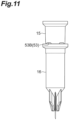
- the piercing tip 15 and the injection tip 16 are the tip set according to the present embodiment.
- the microchip 2 includes a transparent chip main body 21 and a transparent reinforcing film 22 as described in, for example, Japanese Unexamined Patent Publication No. 2017-067595 .
- a reaction space 23 and a confirmation space 24, which are independent of each other, are formed in the chip main body 21.
- the reaction space 23 and the confirmation space 24 are closed spaces formed in the microchip 2.
- the pressure in the reaction space 23 and the confirmation space 24 is reduced with respect to the atmospheric pressure and can be reduced to, for example, 1/100 atm or less.
- the reaction space 23 has an injection space 23a into which a sample solution is puncture-injected, a plurality of reagent-enclosed spaces 23b enclosing a reagent 25 for reacting with the sample solution to be injected, and a flow path 23c allowing the injection space 23a and each reagent-enclosed space 23b to communicate with each other.
- a reagent corresponding to the nucleic acid contained in the sample solution is used as the reagent 25.
- the confirmation space 24 encloses, for example, a color changing agent (not illustrated) that changes color when the sample solution is mixed.
- the chip main body 21 is formed in a thin and substantially rectangular plate shape.
- the chip main body 21 is a two-layer structure of a first plate-shaped portion 26 and a second plate-shaped portion 27 laminated on one surface of the first plate-shaped portion 26.
- the first plate-shaped portion 26 and the second plate-shaped portion 27 are joined in a state where the first plate-shaped portion 26 and the second plate-shaped portion 27 overlap each other.
- the first plate-shaped portion 26 is formed in a thin and substantially rectangular plate shape. Formed on the surface of the first plate-shaped portion 26 that is on the second plate-shaped portion 27 side are a reaction space recess 26a for forming the reaction space 23 and a confirmation space recess (not illustrated) for forming the confirmation space 24.
- the first plate-shaped portion 26 has gas impermeability.
- the material of the first plate-shaped portion 26 is not particularly limited, and gas-impermeable glass, synthetic resin, or the like can be used as the material.
- the synthetic resin include polymethyl methacrylate (PMMA: acrylic resin), polycarbonate (PC), polystyrene (PS), polyethylene terephthalate (PET), COP, and cyclic polyolefin (COC).
- the second plate-shaped portion 27 has a self-sealing property.
- the self-sealing property means that, even when a hole is formed by puncturing or the like, the hole is naturally sealed by a restoring force attributable to self-elastic deformation.
- the elastic material used for the second plate-shaped portion 27 include a silicone-based elastomer, an acrylic-based elastomer, a urethane-based elastomer, and a fluorine-based elastomer. It is preferable that the second plate-shaped portion further has gas permeability, and polydimethylsiloxane (PDMS) as a self-sealing and gas-permeable elastic material can be employed.
- PDMS polydimethylsiloxane
- the dimensions of the microchip 2 are not particularly limited.
- the thickness of the first plate-shaped portion 26 is 2 mm
- the thickness of the second plate-shaped portion 27 is 2 mm
- the depth of the reaction space 23 and the confirmation space 24 is 1.5 mm
- the thickness of the reinforcing film 22 is 0.3 mm.
- the reservoir 31 has a cylindrical portion 33, a flange portion 34, and a holding portion 35.
- the opening 36 is also an opening into which the piercing tip 15 is inserted so that the piercing tip 15 and the injection tip 16 are connected.
- a circumferential groove 39 is formed near the opening 36 in the inner peripheral surface of the cylindrical portion 33.
- the capacity of the reservoir 31, that is, the volume of the internal space A is not particularly limited. Preferably, the volume is larger than 135 ⁇ l. For example, the volume is approximately 200 ⁇ l.
- the dimensions of the injection needle 32 are not particularly limited.
- the thickness of the injection needle 32 is 0.27 mm (31 G)
- the length of the injection needle 32 (total length of the bevel 41, the needle tube 42, and the needle base 43) is 3 mm
- the length of the bevel 41 is 0.7 mm.
- the first cylindrical portion 45 is a part that is inserted into the reservoir 31 from the opening 36 of the injection tip 16 together with the blade portion 44. Accordingly, the blade portion 44 and the first cylindrical portion 45 also function as an insertion portion 50 inserted into the reservoir 31.
- the first cylindrical portion 45 is connected to the upper end of the blade portion 44 and formed in a hollow cylindrical shape extending in the up-down direction.
- the outer diameter of the blade portion 44 is smaller than the inner diameter of the opening 36 of the injection tip 16.
- the maximum outer diameter of the blade portion 44 is also smaller than the inner diameter of the opening 36 of the injection tip 16.
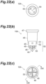
- the piercing tip 15 has one or a plurality of protrusions 52 and one or a plurality of grooves 53.
- the protrusion 52 is a part that functions as a fitting portion fitted to the injection tip 16 and connecting the injection tip 16 and the piercing tip 15.
- the protrusion 52 is formed so as to protrude from the outer peripheral surface of the first cylindrical portion 45. Further, when the insertion portion 50 is inserted in the reservoir 31, the protrusion 52 is fitted to the injection tip 16 by being pressed against the inner peripheral surface of the reservoir 31.
- the protrusion 52 is formed at a position corresponding to the groove 39 when the insertion portion 50 is inserted in the reservoir 31 and the step portion 51 abuts against the upper end surface of the reservoir 31. Accordingly, when the insertion portion 50 is inserted in the reservoir 31, the protrusion 52 is fitted to the injection tip 16 also by fitting into the groove 39 formed in the inner peripheral surface of the cylindrical portion 33.
- Polypropylene or the like can be used as the material of the piercing tip 15, which is not particularly limited.
- the pipette head 3 is moved in the up-down and horizontal directions with the pipette tip 17 mounted.
- the sample solution prepared in the reaction tube 4 is dripped by the pipette tip 17 into the reservoir 31 of the injection tip 16 stored in the second storage well 14B.
- the sample solution is stored in the internal space A of the reservoir 31.
- the pipette tip 17 is removed from the pipette head 3 and the pipette tip 17 removed from the pipette head 3 is collected in the third storage well 14C.
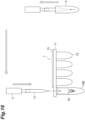
- the second storage well 14B is capable of storing the connected body of the injection tip 16 and the piercing tip 15.
- the piercing tip 15 is stored in the space of the second storage well 14B formed above the injection tip 16 stored in the second storage well 14B.
- the groove 53 allows the internal space A of the reservoir 31 to be ventilated from the outside in a state where the injection tip 16 and the piercing tip 15 are connected, and thus the effect of the internal pressure of the reservoir 31 during sample solution injection from the injection needle 32 into the microchip 2 can be reduced. Accordingly, it is possible to appropriately inject the sample solution from the injection needle 32 into the microchip 2 even when the insertion portion 50 is inserted in the reservoir 31 from the opening 36 and the injection tip 16 and the piercing tip 15 are connected.
Landscapes
- Chemical & Material Sciences (AREA)
- Health & Medical Sciences (AREA)
- Engineering & Computer Science (AREA)
- Genetics & Genomics (AREA)
- Biomedical Technology (AREA)
- Life Sciences & Earth Sciences (AREA)
- Chemical Kinetics & Catalysis (AREA)
- Clinical Laboratory Science (AREA)
- Biotechnology (AREA)
- Wood Science & Technology (AREA)
- General Engineering & Computer Science (AREA)
- Organic Chemistry (AREA)
- Zoology (AREA)
- Bioinformatics & Cheminformatics (AREA)
- Mechanical Engineering (AREA)
- Molecular Biology (AREA)
- Microbiology (AREA)
- Plant Pathology (AREA)
- Biochemistry (AREA)
- General Health & Medical Sciences (AREA)
- Biophysics (AREA)
- Physics & Mathematics (AREA)
- Crystallography & Structural Chemistry (AREA)
- Analytical Chemistry (AREA)
- Automatic Analysis And Handling Materials Therefor (AREA)
- Sampling And Sample Adjustment (AREA)
Claims (5)
- Spitzenset, das für eine genetische Testvorrichtung verwendet wird, wobei das Spitzenset umfasst:eine Durchstech-Spitze (15) zum Durchbrechen eines Deckelabschnitts (13) eines Reagenzbehälters (12), der mit einem Reagenz gefüllt ist, um den Reagenzbehälter (12) zu öffnen; undeine Injektionsspitze (16) zum Injizieren einer Probenlösung, die eine Zielgen-Nukleinsäure enthält, in einen Mikrochip (2), wobeidie Injektionsspitze (16) einen Speicherbehälter (31), der die Probenlösung in einem Innenraum (A) lagert, sowie eine Injektionsnadel (32) aufweist, die von dem Speicherbehälter (31) vorsteht,eine Öffnung (36), die den Innenraum (A) zu einer Seite gegenüberliegend der Injektionsnadel (32) öffnet, in dem Speicherbehälter (31) gebildet ist, unddie Durchstechspitze (15) einen Montageabschnitt (52) aufweist, der an der Injektionsspitze (16) angebracht ist, um die Injektionsspitze (16) und die Durchstechspitze (15) zu verbinden,wobei die Durchstechspitze (15) einen Einführabschnitt (50) aufweist, der in den Speicherbehälter (31) von der Öffnung (36) aus eingeführt wird, und der Montageabschnitt (52) an der Injektionsspitze (16) angebracht wird, wenn der Einführabschnitt (50) in den Speicherbehälter (31) eingeführt wird,wobei der Montageabschnitt (52) ein Vorsprung (52) zum Drücken gegen eine innere Umfangsfläche des Behälters (31) ist, und wobei der Vorsprung (52) von einer äußeren Umfangsfläche des Einführabschnitts (50) vorsteht.
- Spitzenset nach Anspruch 1, wobei zumindest entweder die Durchstechspitze (15) oder die Injektionsspitze (16) weiter eine Belüftungsöffnung (53, 55) aufweist, die eine Belüftung des Innenraums (A) des Speicherbehälters (31) von außen in einem Zustand ermöglichen, in dem die Injektionsspitze (16) und die Durchstechspitze (15) verbunden sind.
- Spitzenset nach Anspruch 2, wobei die Belüftungsöffnung (53) eine Nut (53) ist, die in einer äußeren Umfangsfläche der Durchstechspitze (15) gebildet ist.
- Spitzenset nach Anspruch 3, wobeidie Durchstechspitze (15) einen Stufenabschnitt (51) aufweist, an den eine Endfläche des Speicherbehälters (31) auf der Seite der Öffnung (36) anliegt, unddie Nut (53) ebenfalls in dem Stufenabschnitt (51) gebildet ist.
- Spitzenset nach einem der Ansprüche 1 bis 4, wobeidie Durchstechspitze (15) einen Klingenabschnitt (44) mit einer scharfen Spitze aufweist, undder Klingenabschnitt (44) eine Vielzahl von Klingen (48) aufweist, die sich radial erstrecken und eine Klingenschneide aufweisen, die eine polygonale pyramidenförmige Kantenlinie bildet.
Applications Claiming Priority (2)
| Application Number | Priority Date | Filing Date | Title |
|---|---|---|---|
| JP2017228903 | 2017-11-29 | ||
| PCT/JP2018/042159 WO2019107155A1 (ja) | 2017-11-29 | 2018-11-14 | チップセット |
Publications (3)
| Publication Number | Publication Date |
|---|---|
| EP3719504A1 EP3719504A1 (de) | 2020-10-07 |
| EP3719504A4 EP3719504A4 (de) | 2021-08-18 |
| EP3719504B1 true EP3719504B1 (de) | 2024-07-03 |
Family
ID=66664454
Family Applications (1)
| Application Number | Title | Priority Date | Filing Date |
|---|---|---|---|
| EP18882967.5A Active EP3719504B1 (de) | 2017-11-29 | 2018-11-14 | Spitzenset |
Country Status (5)
| Country | Link |
|---|---|
| US (1) | US11325116B2 (de) |
| EP (1) | EP3719504B1 (de) |
| JP (1) | JP7161492B2 (de) |
| CN (1) | CN111247435A (de) |
| WO (1) | WO2019107155A1 (de) |
Families Citing this family (10)
| Publication number | Priority date | Publication date | Assignee | Title |
|---|---|---|---|---|
| WO2021020910A1 (ko) * | 2019-07-30 | 2021-02-04 | 피씨엘 ㈜ | 다중 바이오마커 동시 분석 기기 및 다중 바이오마커 동시 분석 방법 |
| TWI742958B (zh) * | 2020-12-09 | 2021-10-11 | 瑞基海洋生物科技股份有限公司 | 生化反應器的卡匣 |
| CN114763514A (zh) * | 2021-01-14 | 2022-07-19 | 瑞基海洋生物科技股份有限公司 | 生化反应器的卡匣 |
| CN115684615A (zh) * | 2021-07-23 | 2023-02-03 | 深圳市帝迈生物技术有限公司 | 试剂盒及poct血细胞分析仪 |
| KR102696399B1 (ko) * | 2022-03-08 | 2024-08-20 | 주식회사 유진셀 | 바이알 용기 및 검사 카트리지 |
| JPWO2023182165A1 (de) * | 2022-03-22 | 2023-09-28 | ||
| CN116948778A (zh) * | 2022-04-18 | 2023-10-27 | 厦门致善生物科技股份有限公司 | 一种反应装置、反应系统及其操作方法 |
| DE202022104567U1 (de) * | 2022-08-11 | 2023-11-16 | M L S Mikrowellen - Labor - Systeme GmbH | Probenbehältersystem |
| EP4393597A1 (de) * | 2022-12-27 | 2024-07-03 | TECAN Trading AG | Pipettenspitzenadapter |
| JPWO2024171592A1 (de) * | 2023-02-15 | 2024-08-22 |
Family Cites Families (12)
| Publication number | Priority date | Publication date | Assignee | Title |
|---|---|---|---|---|
| US5895631A (en) | 1995-03-20 | 1999-04-20 | Precision System Science Co., Ltd. | Liquid processing method making use of pipette device and apparatus for same |
| US20060171851A1 (en) | 2005-01-28 | 2006-08-03 | Arta Motadel | Liquid sampling utilizing ribbed pipette tip for barrier penetration |
| JP2006208373A (ja) * | 2005-01-28 | 2006-08-10 | Molecular Bioproducts Inc | バリヤー貫通のためのリブを有するピペットチップを使用した液体採取 |
| EP2439537A1 (de) * | 2009-06-04 | 2012-04-11 | Universal Bio Research Co., Ltd. | Probentestvorrichtung und verfahren dafür |
| EP2618933A1 (de) | 2010-09-23 | 2013-07-31 | Porex Corporation | Gefilterter adapter für pipettierer |
| JP2012159337A (ja) | 2011-01-31 | 2012-08-23 | Sony Corp | サンプル液供給治具、サンプル液供給治具セット及びマイクロチップセット |
| EP2784516A4 (de) | 2011-11-25 | 2015-08-26 | Toppan Printing Co Ltd | Pipettenspitzensatz zur verwendung in einer abgabevorrichtung und verfahren zur perforierung eines reagenzkassettenfilms damit |
| JP3180120U (ja) * | 2012-09-21 | 2012-12-06 | 株式会社島津製作所 | キャップピアッシング用穿孔針 |
| JP6591897B2 (ja) * | 2014-01-16 | 2019-10-16 | ユニバーサル・バイオ・リサーチ株式会社 | 軟質栓貫通分注装置および軟質栓貫通分注方法 |
| JP6812797B2 (ja) * | 2014-11-04 | 2021-01-13 | 凸版印刷株式会社 | 核酸導入方法、核酸検出方法、生体成分解析方法、生体成分定量用アレイデバイス、及び生体成分解析キット |
| JP6621636B2 (ja) | 2015-09-30 | 2019-12-18 | 栄研化学株式会社 | マイクロチップ |
| DE202016007102U1 (de) * | 2016-11-21 | 2017-01-26 | Deutsches Krebsforschungszentrum Stiftung des öffentlichen Rechts | Absaugvorrichtung für Flüssigkeiten mit Unterdruckbegrenzung |
-
2018
- 2018-11-14 CN CN201880068277.4A patent/CN111247435A/zh active Pending
- 2018-11-14 JP JP2019557136A patent/JP7161492B2/ja active Active
- 2018-11-14 EP EP18882967.5A patent/EP3719504B1/de active Active
- 2018-11-14 US US16/766,262 patent/US11325116B2/en active Active
- 2018-11-14 WO PCT/JP2018/042159 patent/WO2019107155A1/ja not_active Ceased
Also Published As
| Publication number | Publication date |
|---|---|
| CN111247435A (zh) | 2020-06-05 |
| US20200368738A1 (en) | 2020-11-26 |
| JPWO2019107155A1 (ja) | 2020-11-19 |
| WO2019107155A1 (ja) | 2019-06-06 |
| JP7161492B2 (ja) | 2022-10-26 |
| EP3719504A1 (de) | 2020-10-07 |
| EP3719504A4 (de) | 2021-08-18 |
| US11325116B2 (en) | 2022-05-10 |
Similar Documents
| Publication | Publication Date | Title |
|---|---|---|
| EP3719504B1 (de) | Spitzenset | |
| JP7561148B2 (ja) | 医学的試料の移送および処理のための再密閉隔壁キャップ | |
| US8387810B2 (en) | Pierceable cap having piercing extensions for a sample container | |
| US8387811B2 (en) | Pierceable cap having piercing extensions | |
| EP3241782B1 (de) | Durchstechbare kappe | |
| US20090246085A1 (en) | Liquid Handling System and Methods for Mixing and Delivering Liquid Reagents | |
| US20110091364A1 (en) | Apparatus for delivering pipettable substances | |
| EP2675420B1 (de) | Durchstechkappe mit einer einzelnen brechbaren dichtung | |
| WO2008076725A1 (en) | Storing and handling liquid reagents | |
| US20060171851A1 (en) | Liquid sampling utilizing ribbed pipette tip for barrier penetration | |
| US20060172433A1 (en) | Liquid sampling utilizing ribbed pipette tip for barrier penetration | |
| CN110622006A (zh) | 试剂盒 | |
| US20080172025A1 (en) | Chemical reaction cartridge and using method thereof | |
| EP2631011B1 (de) | Verschluss mit Septumstreifen | |
| EP4180125B1 (de) | System und methode zur bereitstellung von fluiden in mikrofluidischen produkten | |
| US20210299655A1 (en) | Pcr cartridge | |
| KR102961539B1 (ko) | 의료 샘플 이송 및 처리용 재폐쇄 격막 캡 | |
| US12337323B2 (en) | Closure element for a microplate well having vents and a slot, and method for the use thereof |
Legal Events
| Date | Code | Title | Description |
|---|---|---|---|
| STAA | Information on the status of an ep patent application or granted ep patent |
Free format text: STATUS: THE INTERNATIONAL PUBLICATION HAS BEEN MADE |
|
| PUAI | Public reference made under article 153(3) epc to a published international application that has entered the european phase |
Free format text: ORIGINAL CODE: 0009012 |
|
| STAA | Information on the status of an ep patent application or granted ep patent |
Free format text: STATUS: REQUEST FOR EXAMINATION WAS MADE |
|
| 17P | Request for examination filed |
Effective date: 20200522 |
|
| AK | Designated contracting states |
Kind code of ref document: A1 Designated state(s): AL AT BE BG CH CY CZ DE DK EE ES FI FR GB GR HR HU IE IS IT LI LT LU LV MC MK MT NL NO PL PT RO RS SE SI SK SM TR |
|
| AX | Request for extension of the european patent |
Extension state: BA ME |
|
| DAV | Request for validation of the european patent (deleted) | ||
| DAX | Request for extension of the european patent (deleted) | ||
| A4 | Supplementary search report drawn up and despatched |
Effective date: 20210721 |
|
| RIC1 | Information provided on ipc code assigned before grant |
Ipc: G01N 35/10 20060101AFI20210715BHEP Ipc: G01N 1/00 20060101ALI20210715BHEP Ipc: G01N 35/02 20060101ALI20210715BHEP Ipc: B01L 3/02 20060101ALI20210715BHEP |
|
| STAA | Information on the status of an ep patent application or granted ep patent |
Free format text: STATUS: EXAMINATION IS IN PROGRESS |
|
| 17Q | First examination report despatched |
Effective date: 20230718 |
|
| GRAP | Despatch of communication of intention to grant a patent |
Free format text: ORIGINAL CODE: EPIDOSNIGR1 |
|
| STAA | Information on the status of an ep patent application or granted ep patent |
Free format text: STATUS: GRANT OF PATENT IS INTENDED |
|
| INTG | Intention to grant announced |
Effective date: 20240208 |
|
| GRAS | Grant fee paid |
Free format text: ORIGINAL CODE: EPIDOSNIGR3 |
|
| P01 | Opt-out of the competence of the unified patent court (upc) registered |
Effective date: 20240424 |
|
| GRAA | (expected) grant |
Free format text: ORIGINAL CODE: 0009210 |
|
| STAA | Information on the status of an ep patent application or granted ep patent |
Free format text: STATUS: THE PATENT HAS BEEN GRANTED |
|
| AK | Designated contracting states |
Kind code of ref document: B1 Designated state(s): AL AT BE BG CH CY CZ DE DK EE ES FI FR GB GR HR HU IE IS IT LI LT LU LV MC MK MT NL NO PL PT RO RS SE SI SK SM TR |
|
| REG | Reference to a national code |
Ref country code: CH Ref legal event code: EP |
|
| REG | Reference to a national code |
Ref country code: DE Ref legal event code: R096 Ref document number: 602018071423 Country of ref document: DE |
|
| REG | Reference to a national code |
Ref country code: LT Ref legal event code: MG9D |
|
| REG | Reference to a national code |
Ref country code: NL Ref legal event code: MP Effective date: 20240703 |
|
| PG25 | Lapsed in a contracting state [announced via postgrant information from national office to epo] |
Ref country code: PT Free format text: LAPSE BECAUSE OF FAILURE TO SUBMIT A TRANSLATION OF THE DESCRIPTION OR TO PAY THE FEE WITHIN THE PRESCRIBED TIME-LIMIT Effective date: 20241104 |
|
| REG | Reference to a national code |
Ref country code: AT Ref legal event code: MK05 Ref document number: 1700346 Country of ref document: AT Kind code of ref document: T Effective date: 20240703 |
|
| PG25 | Lapsed in a contracting state [announced via postgrant information from national office to epo] |
Ref country code: NL Free format text: LAPSE BECAUSE OF FAILURE TO SUBMIT A TRANSLATION OF THE DESCRIPTION OR TO PAY THE FEE WITHIN THE PRESCRIBED TIME-LIMIT Effective date: 20240703 |
|
| PG25 | Lapsed in a contracting state [announced via postgrant information from national office to epo] |
Ref country code: PT Free format text: LAPSE BECAUSE OF FAILURE TO SUBMIT A TRANSLATION OF THE DESCRIPTION OR TO PAY THE FEE WITHIN THE PRESCRIBED TIME-LIMIT Effective date: 20241104 Ref country code: NL Free format text: LAPSE BECAUSE OF FAILURE TO SUBMIT A TRANSLATION OF THE DESCRIPTION OR TO PAY THE FEE WITHIN THE PRESCRIBED TIME-LIMIT Effective date: 20240703 |
|
| PG25 | Lapsed in a contracting state [announced via postgrant information from national office to epo] |
Ref country code: NO Free format text: LAPSE BECAUSE OF FAILURE TO SUBMIT A TRANSLATION OF THE DESCRIPTION OR TO PAY THE FEE WITHIN THE PRESCRIBED TIME-LIMIT Effective date: 20241003 |
|
| PG25 | Lapsed in a contracting state [announced via postgrant information from national office to epo] |
Ref country code: PL Free format text: LAPSE BECAUSE OF FAILURE TO SUBMIT A TRANSLATION OF THE DESCRIPTION OR TO PAY THE FEE WITHIN THE PRESCRIBED TIME-LIMIT Effective date: 20240703 Ref country code: FI Free format text: LAPSE BECAUSE OF FAILURE TO SUBMIT A TRANSLATION OF THE DESCRIPTION OR TO PAY THE FEE WITHIN THE PRESCRIBED TIME-LIMIT Effective date: 20240703 Ref country code: GR Free format text: LAPSE BECAUSE OF FAILURE TO SUBMIT A TRANSLATION OF THE DESCRIPTION OR TO PAY THE FEE WITHIN THE PRESCRIBED TIME-LIMIT Effective date: 20241004 |
|
| PG25 | Lapsed in a contracting state [announced via postgrant information from national office to epo] |
Ref country code: BG Free format text: LAPSE BECAUSE OF FAILURE TO SUBMIT A TRANSLATION OF THE DESCRIPTION OR TO PAY THE FEE WITHIN THE PRESCRIBED TIME-LIMIT Effective date: 20240703 |
|
| PG25 | Lapsed in a contracting state [announced via postgrant information from national office to epo] |
Ref country code: LV Free format text: LAPSE BECAUSE OF FAILURE TO SUBMIT A TRANSLATION OF THE DESCRIPTION OR TO PAY THE FEE WITHIN THE PRESCRIBED TIME-LIMIT Effective date: 20240703 |
|
| PG25 | Lapsed in a contracting state [announced via postgrant information from national office to epo] |
Ref country code: IS Free format text: LAPSE BECAUSE OF FAILURE TO SUBMIT A TRANSLATION OF THE DESCRIPTION OR TO PAY THE FEE WITHIN THE PRESCRIBED TIME-LIMIT Effective date: 20241103 Ref country code: AT Free format text: LAPSE BECAUSE OF FAILURE TO SUBMIT A TRANSLATION OF THE DESCRIPTION OR TO PAY THE FEE WITHIN THE PRESCRIBED TIME-LIMIT Effective date: 20240703 |
|
| PG25 | Lapsed in a contracting state [announced via postgrant information from national office to epo] |
Ref country code: CZ Free format text: LAPSE BECAUSE OF FAILURE TO SUBMIT A TRANSLATION OF THE DESCRIPTION OR TO PAY THE FEE WITHIN THE PRESCRIBED TIME-LIMIT Effective date: 20240703 Ref country code: HR Free format text: LAPSE BECAUSE OF FAILURE TO SUBMIT A TRANSLATION OF THE DESCRIPTION OR TO PAY THE FEE WITHIN THE PRESCRIBED TIME-LIMIT Effective date: 20240703 |
|
| PG25 | Lapsed in a contracting state [announced via postgrant information from national office to epo] |
Ref country code: ES Free format text: LAPSE BECAUSE OF FAILURE TO SUBMIT A TRANSLATION OF THE DESCRIPTION OR TO PAY THE FEE WITHIN THE PRESCRIBED TIME-LIMIT Effective date: 20240703 Ref country code: RS Free format text: LAPSE BECAUSE OF FAILURE TO SUBMIT A TRANSLATION OF THE DESCRIPTION OR TO PAY THE FEE WITHIN THE PRESCRIBED TIME-LIMIT Effective date: 20241003 |
|
| PG25 | Lapsed in a contracting state [announced via postgrant information from national office to epo] |
Ref country code: RS Free format text: LAPSE BECAUSE OF FAILURE TO SUBMIT A TRANSLATION OF THE DESCRIPTION OR TO PAY THE FEE WITHIN THE PRESCRIBED TIME-LIMIT Effective date: 20241003 Ref country code: PL Free format text: LAPSE BECAUSE OF FAILURE TO SUBMIT A TRANSLATION OF THE DESCRIPTION OR TO PAY THE FEE WITHIN THE PRESCRIBED TIME-LIMIT Effective date: 20240703 Ref country code: NO Free format text: LAPSE BECAUSE OF FAILURE TO SUBMIT A TRANSLATION OF THE DESCRIPTION OR TO PAY THE FEE WITHIN THE PRESCRIBED TIME-LIMIT Effective date: 20241003 Ref country code: LV Free format text: LAPSE BECAUSE OF FAILURE TO SUBMIT A TRANSLATION OF THE DESCRIPTION OR TO PAY THE FEE WITHIN THE PRESCRIBED TIME-LIMIT Effective date: 20240703 Ref country code: IS Free format text: LAPSE BECAUSE OF FAILURE TO SUBMIT A TRANSLATION OF THE DESCRIPTION OR TO PAY THE FEE WITHIN THE PRESCRIBED TIME-LIMIT Effective date: 20241103 Ref country code: HR Free format text: LAPSE BECAUSE OF FAILURE TO SUBMIT A TRANSLATION OF THE DESCRIPTION OR TO PAY THE FEE WITHIN THE PRESCRIBED TIME-LIMIT Effective date: 20240703 Ref country code: GR Free format text: LAPSE BECAUSE OF FAILURE TO SUBMIT A TRANSLATION OF THE DESCRIPTION OR TO PAY THE FEE WITHIN THE PRESCRIBED TIME-LIMIT Effective date: 20241004 Ref country code: FI Free format text: LAPSE BECAUSE OF FAILURE TO SUBMIT A TRANSLATION OF THE DESCRIPTION OR TO PAY THE FEE WITHIN THE PRESCRIBED TIME-LIMIT Effective date: 20240703 Ref country code: ES Free format text: LAPSE BECAUSE OF FAILURE TO SUBMIT A TRANSLATION OF THE DESCRIPTION OR TO PAY THE FEE WITHIN THE PRESCRIBED TIME-LIMIT Effective date: 20240703 Ref country code: CZ Free format text: LAPSE BECAUSE OF FAILURE TO SUBMIT A TRANSLATION OF THE DESCRIPTION OR TO PAY THE FEE WITHIN THE PRESCRIBED TIME-LIMIT Effective date: 20240703 Ref country code: BG Free format text: LAPSE BECAUSE OF FAILURE TO SUBMIT A TRANSLATION OF THE DESCRIPTION OR TO PAY THE FEE WITHIN THE PRESCRIBED TIME-LIMIT Effective date: 20240703 Ref country code: AT Free format text: LAPSE BECAUSE OF FAILURE TO SUBMIT A TRANSLATION OF THE DESCRIPTION OR TO PAY THE FEE WITHIN THE PRESCRIBED TIME-LIMIT Effective date: 20240703 |
|
| REG | Reference to a national code |
Ref country code: DE Ref legal event code: R097 Ref document number: 602018071423 Country of ref document: DE |
|
| PG25 | Lapsed in a contracting state [announced via postgrant information from national office to epo] |
Ref country code: SM Free format text: LAPSE BECAUSE OF FAILURE TO SUBMIT A TRANSLATION OF THE DESCRIPTION OR TO PAY THE FEE WITHIN THE PRESCRIBED TIME-LIMIT Effective date: 20240703 Ref country code: DK Free format text: LAPSE BECAUSE OF FAILURE TO SUBMIT A TRANSLATION OF THE DESCRIPTION OR TO PAY THE FEE WITHIN THE PRESCRIBED TIME-LIMIT Effective date: 20240703 Ref country code: RO Free format text: LAPSE BECAUSE OF FAILURE TO SUBMIT A TRANSLATION OF THE DESCRIPTION OR TO PAY THE FEE WITHIN THE PRESCRIBED TIME-LIMIT Effective date: 20240703 |
|
| PG25 | Lapsed in a contracting state [announced via postgrant information from national office to epo] |
Ref country code: EE Free format text: LAPSE BECAUSE OF FAILURE TO SUBMIT A TRANSLATION OF THE DESCRIPTION OR TO PAY THE FEE WITHIN THE PRESCRIBED TIME-LIMIT Effective date: 20240703 |
|
| PG25 | Lapsed in a contracting state [announced via postgrant information from national office to epo] |
Ref country code: IT Free format text: LAPSE BECAUSE OF FAILURE TO SUBMIT A TRANSLATION OF THE DESCRIPTION OR TO PAY THE FEE WITHIN THE PRESCRIBED TIME-LIMIT Effective date: 20240703 Ref country code: SK Free format text: LAPSE BECAUSE OF FAILURE TO SUBMIT A TRANSLATION OF THE DESCRIPTION OR TO PAY THE FEE WITHIN THE PRESCRIBED TIME-LIMIT Effective date: 20240703 |
|
| PLBE | No opposition filed within time limit |
Free format text: ORIGINAL CODE: 0009261 |
|
| STAA | Information on the status of an ep patent application or granted ep patent |
Free format text: STATUS: NO OPPOSITION FILED WITHIN TIME LIMIT |
|
| 26N | No opposition filed |
Effective date: 20250404 |
|
| REG | Reference to a national code |
Ref country code: CH Ref legal event code: PL |
|
| PG25 | Lapsed in a contracting state [announced via postgrant information from national office to epo] |
Ref country code: MC Free format text: LAPSE BECAUSE OF FAILURE TO SUBMIT A TRANSLATION OF THE DESCRIPTION OR TO PAY THE FEE WITHIN THE PRESCRIBED TIME-LIMIT Effective date: 20240703 |
|
| PG25 | Lapsed in a contracting state [announced via postgrant information from national office to epo] |
Ref country code: LU Free format text: LAPSE BECAUSE OF NON-PAYMENT OF DUE FEES Effective date: 20241114 |
|
| REG | Reference to a national code |
Ref country code: CH Ref legal event code: PL |
|
| PG25 | Lapsed in a contracting state [announced via postgrant information from national office to epo] |
Ref country code: CH Free format text: LAPSE BECAUSE OF NON-PAYMENT OF DUE FEES Effective date: 20241130 |
|
| REG | Reference to a national code |
Ref country code: BE Ref legal event code: MM Effective date: 20241130 |
|
| PG25 | Lapsed in a contracting state [announced via postgrant information from national office to epo] |
Ref country code: SE Free format text: LAPSE BECAUSE OF FAILURE TO SUBMIT A TRANSLATION OF THE DESCRIPTION OR TO PAY THE FEE WITHIN THE PRESCRIBED TIME-LIMIT Effective date: 20240703 |
|
| PG25 | Lapsed in a contracting state [announced via postgrant information from national office to epo] |
Ref country code: BE Free format text: LAPSE BECAUSE OF NON-PAYMENT OF DUE FEES Effective date: 20241130 |
|
| PG25 | Lapsed in a contracting state [announced via postgrant information from national office to epo] |
Ref country code: IE Free format text: LAPSE BECAUSE OF NON-PAYMENT OF DUE FEES Effective date: 20241114 |
|
| PGFP | Annual fee paid to national office [announced via postgrant information from national office to epo] |
Ref country code: DE Payment date: 20251118 Year of fee payment: 8 |
|
| PGFP | Annual fee paid to national office [announced via postgrant information from national office to epo] |
Ref country code: GB Payment date: 20251117 Year of fee payment: 8 |
|
| PGFP | Annual fee paid to national office [announced via postgrant information from national office to epo] |
Ref country code: FR Payment date: 20251117 Year of fee payment: 8 |
|
| PG25 | Lapsed in a contracting state [announced via postgrant information from national office to epo] |
Ref country code: HU Free format text: LAPSE BECAUSE OF FAILURE TO SUBMIT A TRANSLATION OF THE DESCRIPTION OR TO PAY THE FEE WITHIN THE PRESCRIBED TIME-LIMIT; INVALID AB INITIO Effective date: 20181114 |
|
| PG25 | Lapsed in a contracting state [announced via postgrant information from national office to epo] |
Ref country code: CY Free format text: LAPSE BECAUSE OF FAILURE TO SUBMIT A TRANSLATION OF THE DESCRIPTION OR TO PAY THE FEE WITHIN THE PRESCRIBED TIME-LIMIT; INVALID AB INITIO Effective date: 20181114 |