EP3719601B1 - Système de détermination d'anomalie, dispositif de commande de moteur, et dispositif de détermination d'anomalie - Google Patents
Système de détermination d'anomalie, dispositif de commande de moteur, et dispositif de détermination d'anomalie Download PDFInfo
- Publication number
- EP3719601B1 EP3719601B1 EP18884019.3A EP18884019A EP3719601B1 EP 3719601 B1 EP3719601 B1 EP 3719601B1 EP 18884019 A EP18884019 A EP 18884019A EP 3719601 B1 EP3719601 B1 EP 3719601B1
- Authority
- EP
- European Patent Office
- Prior art keywords
- abnormality
- data
- determination
- motor
- time
- Prior art date
- Legal status (The legal status is an assumption and is not a legal conclusion. Google has not performed a legal analysis and makes no representation as to the accuracy of the status listed.)
- Active
Links
Images





Classifications
-
- G—PHYSICS
- G01—MEASURING; TESTING
- G01R—MEASURING ELECTRIC VARIABLES; MEASURING MAGNETIC VARIABLES
- G01R31/00—Arrangements for testing electric properties; Arrangements for locating electric faults; Arrangements for electrical testing characterised by what is being tested not provided for elsewhere
- G01R31/34—Testing dynamo-electric machines
- G01R31/343—Testing dynamo-electric machines in operation
-
- G—PHYSICS
- G05—CONTROLLING; REGULATING
- G05B—CONTROL OR REGULATING SYSTEMS IN GENERAL; FUNCTIONAL ELEMENTS OF SUCH SYSTEMS; MONITORING OR TESTING ARRANGEMENTS FOR SUCH SYSTEMS OR ELEMENTS
- G05B23/00—Testing or monitoring of control systems or parts thereof
- G05B23/02—Electric testing or monitoring
- G05B23/0205—Electric testing or monitoring by means of a monitoring system capable of detecting and responding to faults
- G05B23/0218—Electric testing or monitoring by means of a monitoring system capable of detecting and responding to faults characterised by the fault detection method dealing with either existing or incipient faults
- G05B23/0224—Process history based detection method, e.g. whereby history implies the availability of large amounts of data
- G05B23/024—Quantitative history assessment, e.g. mathematical relationships between available data; Functions therefor; Principal component analysis [PCA]; Partial least square [PLS]; Statistical classifiers, e.g. Bayesian networks, linear regression or correlation analysis; Neural networks
-
- G—PHYSICS
- G06—COMPUTING OR CALCULATING; COUNTING
- G06N—COMPUTING ARRANGEMENTS BASED ON SPECIFIC COMPUTATIONAL MODELS
- G06N3/00—Computing arrangements based on biological models
- G06N3/02—Neural networks
- G06N3/04—Architecture, e.g. interconnection topology
- G06N3/0464—Convolutional networks [CNN, ConvNet]
-
- G—PHYSICS
- G06—COMPUTING OR CALCULATING; COUNTING
- G06N—COMPUTING ARRANGEMENTS BASED ON SPECIFIC COMPUTATIONAL MODELS
- G06N3/00—Computing arrangements based on biological models
- G06N3/02—Neural networks
- G06N3/08—Learning methods
-
- G—PHYSICS
- G06—COMPUTING OR CALCULATING; COUNTING
- G06N—COMPUTING ARRANGEMENTS BASED ON SPECIFIC COMPUTATIONAL MODELS
- G06N3/00—Computing arrangements based on biological models
- G06N3/02—Neural networks
- G06N3/08—Learning methods
- G06N3/09—Supervised learning
-
- H—ELECTRICITY
- H02—GENERATION; CONVERSION OR DISTRIBUTION OF ELECTRIC POWER
- H02P—CONTROL OR REGULATION OF ELECTRIC MOTORS, ELECTRIC GENERATORS OR DYNAMO-ELECTRIC CONVERTERS; CONTROLLING TRANSFORMERS, REACTORS OR CHOKE COILS
- H02P23/00—Arrangements or methods for the control of AC motors characterised by a control method other than vector control
- H02P23/0004—Control strategies in general, e.g. linear type, e.g. P, PI, PID, using robust control
- H02P23/0018—Control strategies in general, e.g. linear type, e.g. P, PI, PID, using robust control using neural networks
-
- H—ELECTRICITY
- H02—GENERATION; CONVERSION OR DISTRIBUTION OF ELECTRIC POWER
- H02P—CONTROL OR REGULATION OF ELECTRIC MOTORS, ELECTRIC GENERATORS OR DYNAMO-ELECTRIC CONVERTERS; CONTROLLING TRANSFORMERS, REACTORS OR CHOKE COILS
- H02P29/00—Arrangements for regulating or controlling electric motors, appropriate for both AC and DC motors
- H02P29/02—Providing protection against overload without automatic interruption of supply
- H02P29/024—Detecting a fault condition, e.g. short circuit, locked rotor, open circuit or loss of load
-
- H—ELECTRICITY
- H02—GENERATION; CONVERSION OR DISTRIBUTION OF ELECTRIC POWER
- H02P—CONTROL OR REGULATION OF ELECTRIC MOTORS, ELECTRIC GENERATORS OR DYNAMO-ELECTRIC CONVERTERS; CONTROLLING TRANSFORMERS, REACTORS OR CHOKE COILS
- H02P6/00—Arrangements for controlling synchronous motors or other dynamo-electric motors using electronic commutation dependent on the rotor position; Electronic commutators therefor
- H02P6/12—Monitoring commutation; Providing indication of commutation failure
Definitions
- the embodiments disclosed herein relate to an abnormality determination system, a motor control apparatus, and an abnormality determination apparatus.
- Patent document 1 and patent document 2 disclose a technique of performing foretaste diagnosis of a state of mechanical equipment by analyzing sensor data based on a statistical method.
- US 2017/0242076 A1 relates to abnormality detection in a mechanical system. Time series of data like motor input and output are acquired and different strategies, e.g. machine learning, are shown to determine whether abnormalities occur.
- the above-described conventional technique can do no further than to perform state diagnosis of whether a mechanical system is normal or abnormal; that is, it is impossible by the conventional technique to determine a specific content of an equipment abnormality.
- the present invention has been made in view of the above circumstances, and it is an object of the present invention to provide an abnormality determination system, a motor control apparatus, and an abnormality determination apparatus that are capable of determining a specific content of an equipment abnormality in a mechanical system.
- an abnormality determination system according to claim 1 is provided.
- the above-described aspect of the present invention make it possible to determine a specific content of an equipment abnormality in a mechanical system.
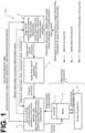
- FIG. 1 an example general arrangement of an abnormality determination system according to this embodiment will be described.
- FIG. 1 illustrates a schematic block configuration of the abnormality determination system.
- an abnormality determination system 100 includes a motor-driven mechanism 1, a servo amplifier 2, an upper-level control apparatus 3, and an edge server 4.
- the motor-driven mechanism 1 is a mechanical system whose driving is controlled by the abnormality determination system 100 and is a target of determination as to various kinds of abnormality associated with the driving.
- the motor-driven mechanism 1 includes: a motor 12, which includes an encoder 11; and a driven machine 13, which is driven by the motor 12.
- the motor 12 is a rotary electric motor
- the encoder 11 is a sensor that optically detects and outputs a rotational angle of the motor
- the driven mechanism 13 is a timing belt mechanism (not illustrated) that rotates a timing belt.
- the servo amplifier 2 (motor control apparatus) has a function (motor driving control function) of feeding driving power to the motor 12 to control driving of the motor 12 so that the output position of the motor 12 follows a position command input from the upper-level control apparatus 3, described later. Also in this embodiment, the servo amplifier 2 also has a function of successively obtaining four pieces of data as time-series detection data (see FIG. 2 , described later) and outputting the four pieces of data to the edge server 4, described later.
- the four pieces of data are: a torque command generated in the process of feeding driving power; output speed generated based on the output position of the motor 12 output from the encoder 11; estimated external disturbance; and speed error.
- the servo amplifier 2 also has a function of making a data abnormality determination based on the above-described time-series detection data and making an equipment abnormality occurrence determination based on how the data abnormality determination was made (this will be described in detail later).
- the upper-level control apparatus 3 has a function (motion control function) of, based on an upper-level control command, described later, input from the edge server, successively outputting a position command to the motor 12 to cause the driven machine 13 to make a desired, time-dependent driving motion.
- the edge server 4 (abnormality determination apparatus) is implemented by, for example, a general-purpose personal computer, and has a function of outputting an upper-level control command to the upper-level control apparatus 3 so as to cause the driven machine 13 to make a desired, time-dependent driving motion. It is to be noted that the upper-level control command may be output to the upper-level control apparatus 3 through another PLC (Programmable Logic Controller), not illustrated. Also in this embodiment, the edge server 4 also has: a function of performing preparation processing before normal operation of the abnormality determination system 100 (that is, during normal driving, described later); and a function of making an equipment abnormality cause estimation in the motor-driven mechanism 1 during the normal operation (that is, at observation driving time, described later).
- the edge server 4 performs the following processing based on the time-series detection data input from the servo amplifier 2 during normal driving, described later.
- the processing includes: calculating sample mean, sample covariance matrix, and data abnormality determination threshold, which are necessary when the servo amplifier 2 and the edge server 4 make the data abnormality determination; and outputting the sample mean, the sample covariance matrix, and the data abnormality determination threshold to the servo amplifier 2 (see FIG. 5 , described later).
- the edge server 4 also has a function of: storing the time-series detection data input from the servo amplifier 2; and, at the observation driving time, described later, making a data abnormality determination based on the time-series detection data and making a motion abnormality kind determination and an equipment abnormality cause estimation based on how the data abnormality determination was made.
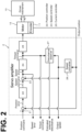
- FIG. 2 is a schematic illustrating, in transfer function form, a control block of the servo amplifier 2 according to this embodiment. It is to be noted that in this embodiment, the control block illustrated in FIG. 2 is implemented in the form of software executed by CPU (not illustrated) of the servo amplifier 2.
- the servo amplifier 2 includes a subtractor 21, a position controller 22, a subtractor 23, a speed controller 24, a current controller 25, a speed converter 26, and a disturbance observer 27.
- the subtractor 21 subtracts an output position (feedback position), described later, from a position command input from the upper-level control apparatus 3, and outputs a position error.
- the position controller 22 performs "PID control” and other control based on the position error, and outputs a speed command.
- the subtractor 23 subtracts an output speed (feedback speed), described later, from the speed command, and outputs a speed error.
- the speed controller 24 performs "PID control" and other control based on the speed error, and outputs a torque command.
- the current controller 25 performs power conversion based on the torque command, and outputs and feeds driving power to the motor 12. Then, the encoder 11 detects the output position of the motor 12 as of the time when the motor 12 drives the driven machine 13. Then, the encoder 11 feeds back the output position to the servo amplifier 2. The output position is subtracted from the position command at the subtractor 21 and input into the speed converter 26. The speed converter 26 outputs, based on the output position, an output speed, which is driving speed of the motor 12. It is to be noted that the speed converter 26 may be implemented by, for example, a differentiator that time-differentiates the output position. Based on the torque command and the output speed, the disturbance observer 27 estimates and outputs an external disturbance added to the motor 12.
- the subtractor 21, the position controller 22, the subtractor 23, the speed controller 24, the current controller 25, and the speed converter 26, which have been described above, constitute a double feedback loop made up of a "position control feedback loop” and a "speed control feedback loop", together with the external motor 12 and the external encoder 11. It is to be noted that while the current controller 25 also has a current control feedback loop inside the current controller 25, this loop is not illustrated. In these feedback loops, the output of the position error at the subtractor 21 is equivalent to time-differentiate processing of the position command, and the output of the speed error at the subtractor 23 is equivalent to time-differentiate processing of the speed command.
- the servo amplifier 2 successively detects, as the time-series detection data, the torque command, the output speed, the estimated external disturbance, and the speed error at short intervals, such as at every system cycle, and outputs the time-series detection data to the edge server 4.
- the abnormality determination system 100 makes a determination as to content of an equipment abnormality occurring in the motor-driven mechanism 1.
- the only abnormal state determinable by the servo amplifier 2 is an abnormal state of the motor 12.
- conventional practice was to: use machine learning based on a statistical method to determine a data abnormality in the above-described time-series detection data. Based on how the data abnormality was made, a motion abnormality in the motor 12 could be determined.
- the edge server 4 obtains a state quantity associated with the mechanical system, which includes the motor-driven mechanism 1, the motor 12, and the servo amplifier 2. Then, using a learning content obtained in a machine learning process and based on the state quantity, the edge server 4 determines at least one of: whether the mechanical system has an abnormality; an occurrence position at which the abnormality is occurring; and a cause of the abnormality. For example, content of an equipment abnormality in the motor-driven mechanism 1 is correlated with determination content of a data abnormality in the above-described time-series detection data, which is a state quantity of the motor-driven mechanism 1. In this embodiment, therefore, content of an equipment abnormality in the motor-driven mechanism 1 can be determined. As a result, a specific content of an equipment abnormality in a mechanical system can be determined. Methods of determination as to data abnormality, motion abnormality, and equipment abnormality will be described below in turn.
- Example abnormalities occurrable during driving control of the timing belt mechanism include:
- these abnormalities will be referred to as equipment abnormalities. It will be assumed that these equipment abnormalities include mechanical and/or circuit-related abnormalities in the motor 12 itself, which drives the motor-driven mechanism 1, and in the motor control apparatus that controls driving of the motor 12 (referring to FIG. 1 , the motor control apparatus includes the encoder 11, the servo amplifier 2, the upper-level control apparatus 3, and other peripheral devices associated with motor control).
- abnormalities there are such abnormalities as: degradation of a smoothing capacitor, a power element, and another component included in the servo amplifier 2 (electronic component lifetime degradation); degradation of a dynamic brake circuit (contact point lifetime degradation of a relay used); insulation degradation of a motor coil; and wear degradation of a motor brake.
- equipment abnormalities in the following description, equipment abnormalities in the motor-driven mechanism 1 alone will be described for ease of description.
- the abnormalities associated with motions of the motor 12 are such phenomena as: oscillations that are caused by an equipment abnormality in the motor-driven mechanism 1 and that are occurrable while the motor 12 is making a control motion; an increase in friction; and a momentary increase in friction.
- these abnormalities will be referred to as motion abnormalities (and kinds of the motion abnormalities).
- data abnormality is intended to mean an abnormality in the time-series detection data used to make a determination as to a motion abnormality in the motor 12 and as to the kind of the motion abnormality. Determinations as to these abnormalities will be described below in turn.
- Machine learning is a method that involves expressing this experience as mathematical formulae and performing calculations using a calculator.
- a basic concept of a change detection method by machine learning is to: prepare a normal distribution of a data group that serves as a reference (this data group will be hereinafter referred to as reference data); and check whether data obtained on the operation stage (this data will be hereinafter referred to as observation data) is deviated from the normal distribution.
- time-series detection data D x 1 y 1 , x 2 y 2 , ⁇ ⁇ ⁇ , x n y n
- Hotelling's T 2 method is employed as a change detection method by machine learning.
- Hotelling's T 2 method is a method of multivariate analysis by which changing waveforms of a plurality of kinds of data are observed in parallel to each other. Processing in this method is performed according to the following (Step 1) to (Step 6).
- Data includes normal data and abnormal data, and an indicator of how largely abnormal data is deviated from a normal distribution is false alarm rate ⁇ .
- ⁇ 0.01. It is to be noted that in a theory of probability and statistics, when the false alarm rate is 0, all of data is normal; therefore, the false alarm rate ⁇ is not set at 0 in principle.
- Data abnormality determination threshold a th that satisfies the following equation is calculated based on the false alarm rate ⁇ determined at (Step 1) and the chi-squared distribution calculated at (Step 2).
- 1 ⁇ ⁇ ⁇ 0 a th dx ⁇ 2 x
- sample mean ⁇ (the hat operator is omitted in the text, which also applies in the following description) and sample covariance matrix ⁇ (the hat operator is omitted in the text, which also applies in the following description) are calculated by solving the following equations.
- x (n) denotes n-th kind reference data.
- the data abnormality determination threshold a th calculated at (Step 3) and the Mahalanobis distance a(x') calculated at (Step 5) are compared with each other.
- the Mahalanobis distance a(x') is in excess of the data abnormality determination threshold a th ( a(x') > a th )
- chi-squared distribution is a probability distribution that varies in distribution depending on the degree of freedom M.
- the method using machine learning perform calculations of the sample mean ⁇ , the sample covariance matrix ⁇ , and the Mahalanobis distance a(x') , instead of calculating a normal distribution. These calculations are performed by four basic arithmetic operations, which are simple operations. Therefore, even if these calculations are successively performed at short intervals during operation of the motor-driven mechanism 1 continuing over a long period of time, the calculations would not involve a large amount of processing load. Additionally, even though the equation for calculating the data abnormality determination threshold a th is apparently complicated, the data abnormality determination threshold a th is a time-independent constant and, therefore, needs to be calculated only once in advance.
- the above-described data abnormality determination ensures determination as to, in binary form, presence or absence of an abnormal state in the time-series detection data (that is, whether the time-series detection data is abnormal or normal) when the time-series detection data is seen at the point of time at which the data is obtained. Even if, however, a data abnormality has been identified once, this should not lead to the determination that a motion abnormality or an equipment abnormality is occurring in the mechanical system as a whole, as described later by referring to an experiment. Also, when a data abnormality has occurred a plurality of times, it is possible to estimate content of a motion abnormality directly based on how the data abnormality occurred. This embodiment assumes that the data abnormality frequency gradually increases as aging degradation develops.
- this embodiment determines that the motor-driven mechanism 1 and the motor control apparatus have an equipment abnormality of the kind associated with aging degradation and that the motor 12 has a motion abnormality caused by the equipment abnormality, as illustrated in FIG. 4 .
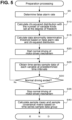
- FIG. 5 is a flowchart of a control procedure for preparation processing corresponding to the above-described Preparation in a case where machine learning is used in a data abnormality determination. This flowchart is performed by CPU of the edge server 4 illustrated in FIG. 1 while the motor-driven mechanism 1 is in normal driving, which is a driving state in which it is certain that substantially no data abnormality occurs.
- a possible example of the normal driving is that after the motor-driven mechanism 1 has been assembled and produced, the motor-driven mechanism 1 is driven in a sufficiently adjusted state and in a state (of initial operation or test operation) in which it is certain that the motor-driven mechanism 1 operates approximately as designed.
- the CPU of the edge server 4 determines false alarm rate ⁇ .
- the determination may be made arbitrarily by a user's input, or may be made on a value calculated based on a preset value or calculated by a predetermined method.
- step S 10 the CPU of the edge server 4 calculates a chi-squared distribution with the number of variable kinds set at M degree of freedom.
- the CPU of the edge server 4 calculates a data abnormality determination threshold a th based on the false alarm rate ⁇ and the chi-squared distribution.
- step S20 the CPU of the edge server 4 starts normal driving of the motor-driven mechanism 1 by performing motion control and motor driving control via the upper-level control apparatus 3 and the servo amplifier 2.
- the CPU of the edge server 4 obtains, from the servo amplifier 2, time-series reference data of each of the variables (torque command and output speed for each axis) at predetermined time intervals, such as in every system cycle.
- step S30 the CPU of the edge server 4 makes a determination as to whether the normal driving has ended. If the normal driving is not ended yet, the determination is not met, and the procedure returns to step S25 so that the same processing is performed again.
- step S35 If, in contrast, the normal driving is not ended, the determination is met, and the procedure proceeds to step S35.
- step S35 the CPU of the edge server 4 stops the normal driving of the motor-driven mechanism 1.
- the CPU of the edge server 4 calculates a sample mean ⁇ and a sample covariance matrix ⁇ based on the time-series reference data group obtained at step S25, thus ending this flow of processing.
- Steps 1 to 4 the preparation processing of machine learning (Steps 1 to 4), which involves a large amount of load of calculation processing, is performed in advance by the edge server 4, which has a comparatively high level of CPU power. This reduces burden on the resources of the abnormality determination system 100 as a whole.
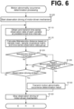
- step S105 the CPU of the servo amplifier 2 starts observation driving of the motor-driven mechanism 1 by performing motion control and motor driving control.
- the CPU of the servo amplifier 2 obtains time-series observation data of each of the variables (torque command and output speed for each axis) at predetermined time intervals, such as in every system cycle, and transmits the time-series observation data to the edge server 4.
- the CPU of the servo amplifier 2 makes a determination as to whether the Mahalanobis distance a(x') calculated at step S115 is in excess of the data abnormality determination threshold a th (simply termed as "threshold" in the drawings) calculated in advance at step S15. In other words, the CPU of the servo amplifier 2 makes a determination as to whether the time-series observation data obtained at step S110 is in a data abnormality state. If the Mahalanobis distance a(x') is not in excess of the data abnormality determination threshold a th , the determination is not met, and the procedure proceeds to step S125. In other words, the CPU of the servo amplifier 2 determines that no data abnormality is occurring.
- step S125 the CPU of the servo amplifier 2 makes a determination as to whether the observation driving has ended. If the observation driving is not ended yet, the determination is not met, and the procedure returns to step S110 so that the same processing is performed again.
- step S130 the CPU of the servo amplifier 2 stops the observation driving of the motor-driven mechanism 1, thus ending this flow of processing.
- step S120 determines that the Mahalanobis distance a(x') is in excess of the data abnormality determination threshold a th . If, in contrast, the determination made at step S120 is that the Mahalanobis distance a(x') is in excess of the data abnormality determination threshold a th , the determination is met, and the procedure proceeds to step S135. In other words, the CPU of the servo amplifier 2 determines that a data abnormality is occurring.
- the CPU of the servo amplifier 2 makes a determination as to how many time-series observation data have been determined as abnormal in a predetermined number of data abnormality determinations that have been made most recently in the past (frequency of abnormalities determined as occurring in time-series observation data); and makes a determination as to whether the frequency is larger than a predetermined value (predetermined threshold).
- predetermined threshold a predetermined value
- the CPU of the servo amplifier 2 makes a determination as to whether an equipment abnormality of the kind associated with aging degradation is occurring. If the frequency in the predetermined number of data abnormality determinations that have been made most recently is larger than the predetermined value, the determination is met, and the procedure proceeds to step S140. In other words, the CPU of the servo amplifier 2 determines that an equipment abnormality of the kind associated with aging degradation is occurring.
- step S140 the CPU of the servo amplifier 2 transmits, to the edge server 4, the determination that an equipment abnormality caused by aging degradation is occurring in the motor-driven mechanism 1 and the motor control apparatus and that an motion abnormality is occurring in the motor 12. Then, the procedure proceeds to step S130.
- step S125 the CPU of the servo amplifier 2 determines that no equipment abnormality caused by aging degradation is occurring.
- the determination processing (steps 5 and 6) and the motion abnormality occurrence determination processing of machine learning, which involve a comparatively small amount of load of calculation processing, is performed by the servo amplifier 2, which has a comparatively low level of CPU power. This reduces burden on the resources of the abnormality determination system 100 as a whole.
- processings at steps S25 and S110 correspond to the time-series detection data obtainer recited in the appended claims; the processings at steps S5, S10, S15, S40, S115, and S120 correspond to the data abnormality determiner recited in the appended claims; and the processing at step S135 corresponds to the motion abnormality occurrence determiner recited in the appended claims.
- processing at step S5 corresponds to the false alarm rate determiner recited in the appended claims
- processing at step S10 corresponds to the chi-squared distribution calculator recited in the appended claims
- processing at step S15 corresponds to the threshold calculator recited in the appended claims
- processing at step S40 corresponds to the sample mean calculator and the sample covariance matrix calculator recited in the appended claims
- processing at step S 115 corresponds to the Mahalanobis distance calculator recited in the appended claims
- processing at step S120 corresponds to the determiner recited in the appended claims.
- the edge server 4 successively receives time-series detection data from the servo amplifier 2 and records time-series detection data, even during observation driving.
- the edge server 4 receives, from the servo amplifier 2, a determination regarding the motion abnormality.
- the edge server 4 itself has already prepared the reference data during the preparation processing for normal driving. This enables the edge server 4 itself to, upon receipt of a motion abnormality occurrence determination from the servo amplifier 2, make a determination as to a data abnormality based on the reference data and the time-series detection data, including calculation of the Mahalanobis distance.
- the edge server 4 can do no further than to determine whether a motion abnormality has occurred in the motor 12.
- the edge server 4 also determines the kind of a motion abnormality based on a time-series distribution pattern of the Mahalanobis distance, as illustrated in the lower half area of FIG. 4 .
- a time-series distribution pattern of the Mahalanobis distance is prepared for each kind of time-series detection data, and does not show a time-series pattern of the time-series detection data itself or a distribution pattern in the frequency domain of the time-series detection data (neither of the patterns is illustrated). Rather, a time-series distribution pattern of the Mahalanobis distance is regarded as emphasizing, in particular, the degree or a characteristic of a motion abnormality in the motor 12.
- the edge server 4 makes a determination as the kind of a motion abnormality by performing pattern matching using machine learning with respect to a time-series distribution pattern of the Mahalanobis distance.
- pattern matching A specific example of the pattern matching will be described below.
- FIG. 7 illustrates an example of a neural network configuration model of a motion abnormality kind determiner of the edge server 4.
- the motion abnormality kind determiner performs kind determination processing with respect to a motion abnormality.
- This motion abnormality kind determiner, 31, is designed and adjusted to perform clustering output of a motion abnormality kind of the motor 12 for a Mahalanobis distance time-series distribution pattern generated for each of the pieces of time-series detection data (torque command, output speed, speed error, and estimated external disturbance).
- the motion abnormality kind that is output is based on a learning content obtained in a machine learning process (deep learning). That is, the neural network of the motion abnormality kind determiner 31 has learned a feature quantity indicating a correlation between a waveform pattern included in the Mahalanobis distance time-series distribution pattern and the motion abnormality kind.
- the layer closest to the input layer may be implemented by, for example, a convolutional neural network (not illustrated), which is a combination of a "convolutional layer” and a “pooling layer”. This configuration ensures flexible pattern recognition.
- a convolutional neural network not illustrated
- the layer closest to the output layer is implemented by a fully connected layer (not illustrated), which is suitable for optimal value operations.
- training data that may be used is a combination of: input data of a Mahalanobis distance time-series distribution pattern generated based on time-series detection data of the motor 12 that is in a motion abnormality state of a known motion abnormality kind; and output data of the motion abnormality kind.
- learning is performed by "back-propagation processing (error back-propagation processing)", which adjusts weight coefficients of the edges connecting the nodes so as to establish a relationship between the input layer and the output layer of the neural network.
- a learning method other than back-propagation may be used; in order to improve processing accuracy, it is possible to use a combination of various known learning methods, such as "stacked auto-encoder”, “dropout, “noise addition”, and “sparse regularization”.
- the processing algorithm of the motion abnormality kind determiner 31 may be implemented by other than deep learning using the neural network illustrated, other possible examples including: other processing algorithms of machine learning (not illustrated) using a support vector machine or a Bayesian network; and other statistical methods. These motion abnormality kind determinations by machine learning and other methods can only be performed by the edge server 4, which has a comparatively high level of CPU power.
- a predetermined relationship rule is used to establish a causal relationship between: the kind of a motion abnormality in the motor 12 attributed to mechanical and/or circuit-related configurations and specifications of the motor-driven mechanism 1; and the cause of an equipment abnormality in the motor-driven mechanism 1 and the motor control apparatus. Then, such causal relationships are stored as a database (not illustrated) in the edge server 4. This ensures that from a previously determined kind of a motion abnormality in the motor 12, the edge server 4 is able to estimate, based on the rule base, the cause of an equipment abnormality occurring in the motor-driven mechanism 1 and the motor control apparatus.
- FIG. 8 collectively illustrates relationships of how various kinds of information flow in various kinds of processing at the time of observation driving of the abnormality determination system 100, described earlier, according to this embodiment. It is to be noted that while the various kinds of processing illustrated can all be performed by the edge server 4, the Mahalanobis distance calculation, the data abnormality determination, and the motion abnormality occurrence determination, which are among the various kinds of processing, are performed by the servo amplifier 2 in this embodiment.
- the abnormality determination system 100 includes: the motion abnormality occurrence determination processing and the motion abnormality kind determiner 31, which make a determination as to a motion abnormality in the motor 12 based on how time-series detection data determined as having a data abnormality was obtained; and the equipment abnormality determiner, which makes a determination as to an equipment abnormality in the motor-driven mechanism 1 and the motor control apparatus based on the determination made by the motion abnormality kind determiner 31.
- the equipment abnormality determiner which makes a determination as to an equipment abnormality in the motor-driven mechanism 1 and the motor control apparatus based on the determination made by the motion abnormality kind determiner 31.
- the data abnormality determiner makes the determination using a Hotelling's T 2 method. This ensures that a data abnormality determination is made highly reliably by multivariate analysis.
- the data abnormality determiner calculates a sample mean ⁇ and a sample covariance matrix ⁇ based on time-series reference data obtained during normal driving. Also, the abnormality determination system 100 calculates a Mahalanobis distance a(x') based on time-series observation data obtained during observation driving, together with the sample mean ⁇ and the sample covariance matrix ⁇ . Then, the abnormality determination system 100 compares the Mahalanobis distance a(x') with a data abnormality determination threshold a th to make a determination as to a data abnormality in the time-series observation data. This ensures that Hotelling's T 2 machine learning can be performed by "supervised learning", improving the reliability of data abnormality determination. It is possible to use machine learning by performing "unsupervised learning” such as clustering.
- the servo amplifier 2 performs motion abnormality occurrence determination processing of making a determination as to whether a motion abnormality is occurring. This ensures that the determination processing (steps 5 and 6) and the motion abnormality occurrence determination processing of machine learning, which involve a comparatively small amount of load of calculation processing, is performed by the servo amplifier 2, which has a comparatively low level of CPU power. This reduces burden on the resources of the abnormality determination system 100 as a whole.
- the servo amplifier 2 makes the determination as to a motion abnormality based on a data abnormality frequency. This ensures that a motion abnormality caused by aging degradation is determined with high reliability. It is to be noted that the method of determining occurrence of a motion abnormality and an equipment abnormality will not be limited to use of data abnormality frequency. For example, it is possible to determine occurrence of a motion abnormality (equipment abnormality) based on various other occurrence forms such as occurrence time, occurrence frequency, and continuation period of a data abnormality. This ensures that determinations based on various motion abnormality kinds including aging degradation are made.
- the motion abnormality kind determiner 31 of the edge server 4 makes a determination as to the kind of a motion abnormality. This ensures that a specific kind of a motion abnormality occurring in the motor 12 is identified.
- the motion abnormality kind determiner 31 of the edge server 4 makes a determination as to the kind of a motion abnormality using pattern matching performed with respect to a time-series distribution pattern of the Mahalanobis distance. This ensures that the kind of a motion abnormality is determined with high accuracy without a design using an artificial mathematical model. It is to be noted that in determining the kind of a motion abnormality, it is not necessary to rely upon Mahalanobis distance time-series distribution patterns corresponding to all the four pieces of time-series detection data illustrated in FIG.
- the time-series pattern data of a state quantity input into the motion abnormality kind determiner 31 will not be limited to a Mahalanobis distance time-series distribution pattern, which is a time-series representation of lengths of Mahalanobis distances at time points of time-series detection data.
- the edge server 4 when the edge server 4 makes a determination as to an equipment abnormality, the edge server 4 estimates a cause of the equipment abnormality. This ensures that details of the cause of an equipment abnormality occurring in the motor-driven mechanism 1 are identified.
- the edge server 4 when the edge server 4 makes the determination as to the cause of an equipment abnormality, the edge server 4 estimates the cause of the equipment abnormality according to a rule base that is based on a determination as to the kind of a motion abnormality. This ensures that the cause of an equipment abnormality is estimated based on a causal relationship between: the kind of a motion abnormality in the motor 12 attributed to the mechanical configuration of the motor-driven mechanism 1; and the kind of an equipment abnormality in the motor-driven mechanism 1 and the motor control apparatus.
- the CPU of the servo amplifier 2 and the CPU of the edge server 4 may not necessarily share the above-described processings in the manner described above, the processings including preparation processing, motion abnormality occurrence determination processing, data abnormality determination, motion abnormality kind determination, and equipment abnormality kind estimation.
- the CPU of the servo amplifier 2, the CPU of the upper-level control apparatus 3, and the CPU of the edge server 4 may be integrated into any combination, and may share the processings in any other manner.
- a possible example, not illustrated, is that the servo amplifier 2 only obtains and transmits time-series detection data, and the edge server 4 performs data abnormality determination, motion abnormality occurrence determination, motion abnormality kind determination, and equipment abnormality kind determination.
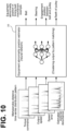
- an equipment abnormality cause estimator 32 which is implemented by a neural network, may directly estimate the cause of the equipment abnormality (in the example illustrated, only an equipment abnormality in the timing belt mechanism is shown) by pattern matching using the Mahalanobis distance time-series distribution pattern of each piece of the time-series detection data. This eliminates the need for performing the determination as to the kind of a motion abnormality in the motor 12, ensuring that the cause of an equipment abnormality in the motor-driven mechanism 1 and the motor control apparatus is estimated with more ease.
- an equipment abnormality position estimator 33 which is implemented by a neural network, may directly estimate the occurrence position of the equipment abnormality (in the example illustrated, only an equipment abnormality in the timing belt mechanism is shown) by pattern matching using the Mahalanobis distance time-series distribution pattern of each piece of the time-series detection data. This ensures that the occurrence position of an equipment abnormality in the motor-driven mechanism 1 and the motor control apparatus is estimated with more ease.
- the cause estimation and position estimation of an equipment abnormality have been described as: estimations from content of a motion abnormality kind determination according to a rule base; or estimations by pattern matching using the Mahalanobis distance time-series distribution pattern of each piece of the time-series detection data. It is also possible, however, to perform cause estimation and position estimation of an equipment abnormality by other than the above-described methods; for example, it is possible to estimate a mechanical characteristic value of the motor-driven mechanism 1 based on each piece of the time-series detection data, which is a state quantity, and perform the cause estimation and the position estimation based on the characteristic value.
- equipment characteristic value examples include: various friction coefficients such as resonance frequency, coulomb friction coefficient, and viscosity friction coefficient; and inertia moment (inertia). These examples may be calculated as estimated values by an operation formula using a predetermined known mathematical model or by an analysis method based on the time-series detection data detected at the servo amplifier 2, namely, torque command, output position, output speed, estimated external disturbance, and speed error. It is to be noted that an example of the analysis method is a mechanical analysis that includes a frequency analysis using, for example, FFT. Alternatively, as illustrated in FIG.
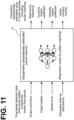
- an equipment characteristic estimator 34 which is implemented by a neural network, may directly estimate, by regression output (multi-valued output), an equipment characteristic estimated value of the motor-driven mechanism 1 (in the example illustrated, only an equipment characteristic value of the motor (including the driven machine) is shown) as of a present point of time by pattern matching using each piece of the time-series detection data.
- a combination of these various equipment characteristic estimated values that have been estimated emphasize characteristics associated with the cause and/or the occurrence position of an equipment abnormality in the motor-driven mechanism 1 at the present point of time.
- FIG. 12 collectively illustrates relationships of how various kinds of information flow in various kinds of processing at the time of observation driving in the above-described modifications. It is to be noted that while the various kinds of processing illustrated can all be performed by the edge server 4, the Mahalanobis distance calculation, the data abnormality determination, and the motion abnormality occurrence determination, which are among the various kinds of processing, are performed by the servo amplifier 2.
- the motor 12 of the motor-driven mechanism 1 may be a linear motor, which is not illustrated, that makes linear motions.
- a linear scale is used instead of the encoder 11, and a thrust command, instead of a torque command, is obtained as time-series detection data.
- perpendicular means substantially or approximately perpendicular within some design tolerance or manufacturing tolerance, as well as precisely perpendicular.
- parallel means substantially or approximately parallel within some design tolerance or manufacturing tolerance, as well as precisely parallel.
- planar means substantially or approximately planar within some design tolerance or manufacturing tolerance, as well as precisely planar.
Landscapes
- Engineering & Computer Science (AREA)
- Physics & Mathematics (AREA)
- General Physics & Mathematics (AREA)
- Evolutionary Computation (AREA)
- Artificial Intelligence (AREA)
- Theoretical Computer Science (AREA)
- Mathematical Physics (AREA)
- Power Engineering (AREA)
- Biophysics (AREA)
- Life Sciences & Earth Sciences (AREA)
- General Health & Medical Sciences (AREA)
- Molecular Biology (AREA)
- Computing Systems (AREA)
- General Engineering & Computer Science (AREA)
- Computational Linguistics (AREA)
- Biomedical Technology (AREA)
- Software Systems (AREA)
- Data Mining & Analysis (AREA)
- Health & Medical Sciences (AREA)
- Automation & Control Theory (AREA)
- Testing And Monitoring For Control Systems (AREA)
- Control Of Electric Motors In General (AREA)
- Algebra (AREA)
- Mathematical Analysis (AREA)
- Mathematical Optimization (AREA)
- Probability & Statistics with Applications (AREA)
- Pure & Applied Mathematics (AREA)
Claims (9)
- Système de détermination d'anomalie (100) comprenant :un dispositif de récupération de valeur d'état (2) configuré pour obtenir une valeur d'état associée à un système mécanique (1), etun dispositif de détermination d'anomalie (4) configuré pour réaliser, en utilisant un contenu d'apprentissage obtenu dans un traitement d'apprentissage machine et sur la base de la valeur d'état, une détermination concernant au moins l'un parmi : le fait que le système mécanique (1) présente une anomalie, la position d'apparition à laquelle se produit l'anomalie et la cause de l'anomalie, oùle système mécanique (1) comprend :un moteur (12),un appareil de commande de moteur configuré pour commander l'entraînement du moteur (12), etun mécanisme entraîné par le moteur (13) pouvant être entraîné par le moteur (12), etdans lequel le dispositif de récupération de valeur d'état (2) comprend un dispositif de récupération de données de détection de séries dans le temps configuré pour récupérer, en tant que valeur d'état, des données de détection de séries dans le temps associées à une entrée et à une sortie du moteur (12) entraîné,caractérisé en ce que :
le dispositif de détermination d'anomalie (4) comprend :un dispositif d'estimation de caractéristique d'équipement (34) configuré pour estimer une valeur estimée de caractéristique d'équipement du système mécanique (1) sur la base des données de détection de séries dans le temps, la caractéristique d'équipement étant au moins l'un d'un coefficient de frottement, d'une fréquence de résonance, d'un coefficient de frottement de Coulomb, d'un coefficient de frottement de viscosité et d'inertie,un dispositif de détermination d'anomalie de données configuré pour réaliser une détermination de ce que les données de détection de séries dans le temps présentent une anomalie de données, etun dispositif de détermination d'anomalie d'équipement configuré pour réaliser la détermination, sur la base de la détermination effectuée par le dispositif de détermination de, de ce que le moteur (12), l'appareil de commande de moteur et/ou le mécanisme entraîné par le moteur (13) présentent une anomalie d'équipement, oùle dispositif de détermination d'anomalie d'équipement comprend un dispositif d'estimation de cause d'anomalie d'équipement (32) configuré pour estimer une cause de l'anomalie d'équipement,dans lequel le dispositif d'estimation de cause d'anomalie d'équipement est configuré pour estimer, sur la base du contenu d'apprentissage récupéré dans le traitement d'apprentissage machine, la cause de l'anomalie d'équipement en utilisant la valeur estimée de caractéristique d'équipement. - Système de détection d'anomalie (100) selon la revendication 1, dans lequel le dispositif de détermination d'anomalie de données est configuré pour réaliser la détermination en utilisant un procédé selon la loi T2 de Hotelling.
- Système de détection d'anomalie (100) selon la revendication 2,dans lequel le dispositif de détermination d'anomalie de données comprend :un dispositif de détermination de taux de fausses alarmes configuré pour déterminer un taux de fausses alarmes,un calculateur de distribution en chi-deux configuré pour calculer une distribution en chi-deux fondée sur un degré de liberté qui spécifie le nombre de types de données de référence indépendante des données de détection en séries dans le temps,un calculateur de seuil configuré pour calculer un seuil de détermination d'anomalie de données fondé sur le taux de fausses alarmes et la distribution en chi-deux,un calculateur de moyenne d'échantillons configuré pour calculer une moyenne d'échantillons fondée sur les données de détection en séries dans le temps,un calculateur de matrice de covariance d'échantillons configuré pour calculer une matrice de covariance d'échantillons fondée sur les données de détection en séries dans le temps,un calculateur de distance de Mahalanobis configuré pour calculer une distance de Mahalanobis sur la base de la moyenne d'échantillons, de la matrice de covariance échantillons et des données de détection en séries dans le temps, etun dispositif de détermination configuré pour comparer l'un à l'autre le seuil de détermination d'anomalie de données et la distance de Mahalanobis afin de réaliser la détermination de ce que les données de détection en séries dans le temps présentent une anomalie de données,dans lequel le calculateur de moyenne d'échantillons et le calculateur de matrice de covariance échantillons sont configurés pour appliquer des données de référence en séries dans le temps récupérées pendant un entrainement normal du mécanisme entraîné par le moteur (13),dans lequel le calculateur de distance de Mahalanobis est configuré pour appliquer des données d'observation en séries dans le temps récupérées pendant un entrainement d'observation du mécanisme entraîné par le moteur (13), etdans lequel le dispositif de détermination est configuré pour réaliser la détermination de ce que les données d'observation en séries dans le temps présentent une anomalie de données.
- Système de détection d'anomalie (100) selon l'une quelconque des revendications 1 à 3, dans lequel le dispositif de détermination d'anomalie d'équipement comprend un dispositif de détermination d'anomalie de mouvement configuré pour réaliser la détermination de ce que le moteur (12) présente une anomalie de mouvement fondée sur le procédé d'obtention des données de détection en séries dans le temps que l'on a déterminé comme présentant une anomalie de données.
- Système de détection d'anomalie (100) selon la revendication 4, dans lequel le dispositif de détermination d'anomalie de mouvement comprend un dispositif de détermination d'apparition d'anomalie de mouvement configuré pour réaliser la détermination de ce que l'anomalie de mouvement apparaît ou non.
- Système de détection d'anomalie (100) selon la revendication 5, dans lequel le dispositif de détermination d'apparition d'anomalie de mouvement est configuré, sur la base d'une fréquence d'anomalie de données, pour réaliser la détermination de ce que l'anomalie de mouvement apparaît ou non.
- Système de détection d'anomalie (100) selon l'une quelconque des revendications 1 à 6, dans lequel le dispositif de détermination d'anomalie de mouvement comprend un dispositif de détermination de type d'anomalie de mouvement (31) configuré pour réaliser la détermination concernant le type de l'anomalie de mouvement.
- Système de détection d'anomalie (100) selon la revendication 7, dans lequel le dispositif de détermination de type d'anomalie de mouvement (31) est configuré, sur la base du contenu d'apprentissage récupéré lors du traitement d'apprentissage machine, pour réaliser la détermination concernant le type de l'anomalie de mouvement en utilisant une correspondance de séquences effectuée par rapport à une séquence de distribution en séries dans le temps de la distance de Mahalanobis.
- Système de détection d'anomalie (100) selon la revendication 7 ou la revendication 8, dans lequel le dispositif d'estimation de cause d'anomalie d'équipement (32) est configuré pour estimer la cause de l'anomalie d'équipement sur la base de la détermination réalisée par le dispositif de détermination de type d'anomalie de mouvement (31) .
Applications Claiming Priority (2)
| Application Number | Priority Date | Filing Date | Title |
|---|---|---|---|
| JP2017228046 | 2017-11-28 | ||
| PCT/JP2018/026097 WO2019106875A1 (fr) | 2017-11-28 | 2018-07-10 | Système de détermination d'anomalie, dispositif de commande de moteur, et dispositif de détermination d'anomalie |
Publications (3)
| Publication Number | Publication Date |
|---|---|
| EP3719601A1 EP3719601A1 (fr) | 2020-10-07 |
| EP3719601A4 EP3719601A4 (fr) | 2021-09-01 |
| EP3719601B1 true EP3719601B1 (fr) | 2024-11-20 |
Family
ID=66664768
Family Applications (1)
| Application Number | Title | Priority Date | Filing Date |
|---|---|---|---|
| EP18884019.3A Active EP3719601B1 (fr) | 2017-11-28 | 2018-07-10 | Système de détermination d'anomalie, dispositif de commande de moteur, et dispositif de détermination d'anomalie |
Country Status (5)
| Country | Link |
|---|---|
| US (1) | US11527984B2 (fr) |
| EP (1) | EP3719601B1 (fr) |
| JP (1) | JP6569927B1 (fr) |
| CN (1) | CN111164526B (fr) |
| WO (1) | WO2019106875A1 (fr) |
Families Citing this family (29)
| Publication number | Priority date | Publication date | Assignee | Title |
|---|---|---|---|---|
| US11983072B2 (en) * | 2019-01-16 | 2024-05-14 | Nec Corporation | Estimation apparatus, estimation method, and computer-readable storage medium |
| JP7101131B2 (ja) * | 2019-01-31 | 2022-07-14 | ファナック株式会社 | 数値制御システム |
| JP7314664B2 (ja) * | 2019-07-05 | 2023-07-26 | オムロン株式会社 | 異常検知装置、異常検知方法、異常検知装置の制御方法、及び制御プログラム |
| JP6932160B2 (ja) * | 2019-07-22 | 2021-09-08 | 株式会社安川電機 | 機械学習方法及び産業用機器のパラメータ又は産業用機器により制御される機器の内部状態の推定方法 |
| JP7489899B2 (ja) * | 2019-10-18 | 2024-05-24 | 株式会社安川電機 | 事象推定システム及び事象推定方法 |
| JP6792043B1 (ja) * | 2019-10-18 | 2020-11-25 | 株式会社安川電機 | 事象推定システム及び事象推定方法 |
| JP7517810B2 (ja) * | 2019-11-19 | 2024-07-17 | 旭化成株式会社 | 診断装置、診断方法及び診断プログラム |
| JP6850458B1 (ja) * | 2019-11-22 | 2021-03-31 | ディエスピーテクノロジ株式会社 | Ai搭載型モータ状態量推定システムおよびモータモデル用機械学習方法 |
| KR102300835B1 (ko) * | 2019-12-05 | 2021-09-10 | (주)심플랫폼 | IoT 데이터 분석을 통한 모니터링 시스템 및 방법 |
| JP2021135780A (ja) * | 2020-02-27 | 2021-09-13 | 株式会社東芝 | 状態監視装置、方法及びプログラム |
| JP2021149727A (ja) * | 2020-03-23 | 2021-09-27 | 本田技研工業株式会社 | 要因分析装置および要因分析方法 |
| JP7226411B2 (ja) * | 2020-08-07 | 2023-02-21 | 株式会社安川電機 | 拡張モジュール、産業用機器、及び産業用機器のパラメータ又は前記産業用機器により制御される機器の内部状態の推定方法 |
| KR102903863B1 (ko) * | 2020-09-18 | 2025-12-23 | 주식회사 엘지화학 | 원심 분리 공정의 사전 이상 진단 방법 |
| JP7648362B2 (ja) * | 2020-10-19 | 2025-03-18 | Ihi運搬機械株式会社 | 異常診断装置及び異常診断方法 |
| US11835568B2 (en) | 2020-11-18 | 2023-12-05 | General Electric Company | Systems and methods for monitoring and diagnosing power system assets |
| JP7508381B2 (ja) * | 2021-01-25 | 2024-07-01 | 株式会社日本製鋼所 | 異常検知システム、成形機システム、異常検知装置、異常検知方法及びコンピュータプログラム |
| DE112021006996T5 (de) * | 2021-02-03 | 2023-11-30 | Mitsubishi Electric Corporation | Anpassungsvorrichtung, Anpassungssystem und Anpassungsverfahren |
| EP4050354B1 (fr) * | 2021-02-25 | 2025-01-01 | Mitsubishi Electric R & D Centre Europe B.V. | Procédé et dispositif de surveillance de l'état d'un moteur |
| JP7503201B2 (ja) * | 2021-03-11 | 2024-06-19 | 株式会社日立産機システム | 電力変換装置 |
| TWI769762B (zh) * | 2021-03-26 | 2022-07-01 | 東元電機股份有限公司 | 應用於伺服馬達驅動系統的波形分析系統及其方法 |
| CN113515671A (zh) * | 2021-07-01 | 2021-10-19 | 河北工业大学 | 继电器时间参数异常值识别方法、服务端及存储介质 |
| CN113609964B (zh) * | 2021-08-03 | 2024-11-26 | 西安市双合软件技术有限公司 | 一种电机异常振动预警方法及系统 |
| KR102541129B1 (ko) * | 2021-08-20 | 2023-06-12 | 유디에스(주) | 기계장비의 상태 진단시스템 및 방법 |
| JP7401499B2 (ja) | 2021-10-01 | 2023-12-19 | 株式会社安川電機 | 異常判定システム、異常判定装置、異常判定方法 |
| JP7430693B2 (ja) * | 2021-10-29 | 2024-02-13 | 株式会社安川電機 | 異常情報推定システム、動作解析システム、モータ制御装置、異常情報推定方法、及びプログラム |
| CN114279555A (zh) * | 2021-12-27 | 2022-04-05 | 深圳市双合电气股份有限公司 | 一种电机异常振动监测方法及系统 |
| JP2024021737A (ja) * | 2022-08-04 | 2024-02-16 | 株式会社Subaru | 車両 |
| JP2024027420A (ja) * | 2022-08-17 | 2024-03-01 | ミネベアミツミ株式会社 | モータ駆動制御装置及びモータ診断方法 |
| JP2026002647A (ja) * | 2024-06-21 | 2026-01-08 | 株式会社デンソー | 故障予知システム |
Family Cites Families (19)
| Publication number | Priority date | Publication date | Assignee | Title |
|---|---|---|---|---|
| JPS5827425B2 (ja) | 1976-11-27 | 1983-06-09 | 株式会社神戸製鋼所 | バルブシ−ト |
| JPS5827426B2 (ja) | 1979-07-18 | 1983-06-09 | 松下電器産業株式会社 | 密封装置 |
| JP2003316422A (ja) * | 2002-04-25 | 2003-11-07 | Mitsubishi Electric Corp | 制御パラメータ自動調整装置 |
| JP4265982B2 (ja) * | 2004-02-25 | 2009-05-20 | 三菱電機株式会社 | 機器診断装置、冷凍サイクル装置、冷凍サイクル監視システム |
| JP4997394B2 (ja) * | 2005-03-31 | 2012-08-08 | 地方独立行政法人山口県産業技術センター | 火災予防監視支援システム |
| JP4480019B2 (ja) * | 2005-04-28 | 2010-06-16 | 財団法人石油産業活性化センター | 製油所監視システム |
| DE112012002333B9 (de) * | 2011-05-31 | 2021-10-14 | Mitsubishi Electric Corp. | Belastungscharakteristikschätzvorrichtung für eine antriebsmaschine |
| CN102798529B (zh) * | 2012-08-30 | 2015-03-25 | 桂林电子科技大学 | 大型风力机组轴承故障诊断方法及系统 |
| CN102944435B (zh) * | 2012-10-25 | 2015-02-11 | 北京航空航天大学 | 一种基于费希尔判别分析与马氏距离的旋转机械健康评估与故障诊断方法 |
| CN104756399B (zh) * | 2013-01-16 | 2017-04-26 | 三菱电机株式会社 | 电动机控制装置 |
| JP6312517B2 (ja) * | 2014-05-07 | 2018-04-18 | 山洋電気株式会社 | モータ制御装置 |
| CN103995229B (zh) * | 2014-05-21 | 2016-06-22 | 浙江工业大学 | 一种基于特征选取和马氏距离的电机健康监测和异常诊断方法 |
| JP5827425B1 (ja) | 2015-01-09 | 2015-12-02 | 株式会社日立パワーソリューションズ | 予兆診断システム及び予兆診断方法 |
| JP5827426B1 (ja) | 2015-01-09 | 2015-12-02 | 株式会社日立パワーソリューションズ | 予兆診断システム及び予兆診断方法 |
| US10038399B2 (en) * | 2015-02-27 | 2018-07-31 | Mitsubishi Electric Corporation | Electric motor control device |
| JP6501673B2 (ja) * | 2015-08-20 | 2019-04-17 | 株式会社熊谷組 | 構造物の劣化判定方法 |
| US10505490B2 (en) * | 2016-02-19 | 2019-12-10 | Hitachi, Ltd. | Motor control system |
| JP6451662B2 (ja) * | 2016-02-23 | 2019-01-16 | 株式会社安川電機 | 異常判定装置、異常判定プログラム、異常判定システム、及びモータ制御装置 |
| JP6593715B2 (ja) * | 2017-10-27 | 2019-10-23 | 株式会社安川電機 | 異常判定システム、モータ制御装置 |
-
2018
- 2018-07-10 WO PCT/JP2018/026097 patent/WO2019106875A1/fr not_active Ceased
- 2018-07-10 CN CN201880063974.0A patent/CN111164526B/zh active Active
- 2018-07-10 JP JP2018554787A patent/JP6569927B1/ja active Active
- 2018-07-10 EP EP18884019.3A patent/EP3719601B1/fr active Active
-
2020
- 2020-05-21 US US16/879,760 patent/US11527984B2/en active Active
Also Published As
| Publication number | Publication date |
|---|---|
| JPWO2019106875A1 (ja) | 2019-12-12 |
| US20200287497A1 (en) | 2020-09-10 |
| WO2019106875A1 (fr) | 2019-06-06 |
| US11527984B2 (en) | 2022-12-13 |
| JP6569927B1 (ja) | 2019-09-04 |
| CN111164526B (zh) | 2023-10-13 |
| CN111164526A (zh) | 2020-05-15 |
| EP3719601A1 (fr) | 2020-10-07 |
| EP3719601A4 (fr) | 2021-09-01 |
Similar Documents
| Publication | Publication Date | Title |
|---|---|---|
| EP3719601B1 (fr) | Système de détermination d'anomalie, dispositif de commande de moteur, et dispositif de détermination d'anomalie | |
| US12066797B2 (en) | Fault prediction method and fault prediction system for predecting a fault of a machine | |
| CN110377447B (zh) | 一种异常数据检测方法、装置及服务器 | |
| Lei et al. | A new method based on stochastic process models for machine remaining useful life prediction | |
| CN110276416B (zh) | 一种滚动轴承故障预测方法 | |
| EP3822595B1 (fr) | Maintenance prédictive pour bras robotiques faisant appel aux mesures de vibration | |
| US10148211B2 (en) | Machine learning apparatus and method for learning correction value in motor current control, correction value computation apparatus including machine learning apparatus and motor driving apparatus | |
| CN108731923B (zh) | 一种旋转机械设备的故障检测方法及装置 | |
| Niu et al. | Intelligent condition monitoring and prognostics system based on data-fusion strategy | |
| US20130060524A1 (en) | Machine Anomaly Detection and Diagnosis Incorporating Operational Data | |
| CN116086537B (zh) | 一种设备状态监测方法、装置、设备及存储介质 | |
| CN117458955A (zh) | 电机的运行控制方法及系统 | |
| Dorj et al. | A bayesian hidden markov model-based approach for anomaly detection in electronic systems | |
| Wang et al. | An evolving fuzzy predictor for industrial applications | |
| CN112350878A (zh) | 一种压力测试系统 | |
| Bilski | Application of support vector machines to the induction motor parameters identification | |
| US20050261837A1 (en) | Kernel-based system and method for estimation-based equipment condition monitoring | |
| JP6721012B2 (ja) | モータ制御システム | |
| JP6828807B2 (ja) | データ解析装置、データ解析方法およびデータ解析プログラム | |
| CN117708728A (zh) | 传感器测量异常检测 | |
| CN119347800B (zh) | 一种晶圆清洗机械臂运动稳定性自适应调节系统及方法 | |
| Medvedew et al. | Diagnostic features space construction using Volterra kernels wavelet transforms | |
| CN114693143A (zh) | 一种数控机床的健康状态评价方法、系统、设备和介质 | |
| Omitaomu et al. | Online support vector regression with varying parameters for time-dependent data | |
| Menon et al. | Evaluating covariance in prognostic and system health management applications |
Legal Events
| Date | Code | Title | Description |
|---|---|---|---|
| STAA | Information on the status of an ep patent application or granted ep patent |
Free format text: STATUS: THE INTERNATIONAL PUBLICATION HAS BEEN MADE |
|
| PUAI | Public reference made under article 153(3) epc to a published international application that has entered the european phase |
Free format text: ORIGINAL CODE: 0009012 |
|
| STAA | Information on the status of an ep patent application or granted ep patent |
Free format text: STATUS: REQUEST FOR EXAMINATION WAS MADE |
|
| 17P | Request for examination filed |
Effective date: 20200506 |
|
| AK | Designated contracting states |
Kind code of ref document: A1 Designated state(s): AL AT BE BG CH CY CZ DE DK EE ES FI FR GB GR HR HU IE IS IT LI LT LU LV MC MK MT NL NO PL PT RO RS SE SI SK SM TR |
|
| AX | Request for extension of the european patent |
Extension state: BA ME |
|
| DAV | Request for validation of the european patent (deleted) | ||
| DAX | Request for extension of the european patent (deleted) | ||
| A4 | Supplementary search report drawn up and despatched |
Effective date: 20210802 |
|
| RIC1 | Information provided on ipc code assigned before grant |
Ipc: G05B 23/02 20060101AFI20210727BHEP Ipc: H02P 29/024 20160101ALI20210727BHEP |
|
| STAA | Information on the status of an ep patent application or granted ep patent |
Free format text: STATUS: EXAMINATION IS IN PROGRESS |
|
| 17Q | First examination report despatched |
Effective date: 20230417 |
|
| RIC1 | Information provided on ipc code assigned before grant |
Ipc: H02P 29/024 20160101ALI20240624BHEP Ipc: H02P 23/00 20160101ALI20240624BHEP Ipc: G05B 23/02 20060101AFI20240624BHEP |
|
| GRAP | Despatch of communication of intention to grant a patent |
Free format text: ORIGINAL CODE: EPIDOSNIGR1 |
|
| STAA | Information on the status of an ep patent application or granted ep patent |
Free format text: STATUS: GRANT OF PATENT IS INTENDED |
|
| INTG | Intention to grant announced |
Effective date: 20240820 |
|
| GRAS | Grant fee paid |
Free format text: ORIGINAL CODE: EPIDOSNIGR3 |
|
| GRAA | (expected) grant |
Free format text: ORIGINAL CODE: 0009210 |
|
| STAA | Information on the status of an ep patent application or granted ep patent |
Free format text: STATUS: THE PATENT HAS BEEN GRANTED |
|
| AK | Designated contracting states |
Kind code of ref document: B1 Designated state(s): AL AT BE BG CH CY CZ DE DK EE ES FI FR GB GR HR HU IE IS IT LI LT LU LV MC MK MT NL NO PL PT RO RS SE SI SK SM TR |
|
| REG | Reference to a national code |
Ref country code: GB Ref legal event code: FG4D |
|
| REG | Reference to a national code |
Ref country code: CH Ref legal event code: EP |
|
| REG | Reference to a national code |
Ref country code: DE Ref legal event code: R096 Ref document number: 602018076832 Country of ref document: DE |
|
| REG | Reference to a national code |
Ref country code: IE Ref legal event code: FG4D |
|
| REG | Reference to a national code |
Ref country code: LT Ref legal event code: MG9D |
|
| REG | Reference to a national code |
Ref country code: NL Ref legal event code: MP Effective date: 20241120 |
|
| PG25 | Lapsed in a contracting state [announced via postgrant information from national office to epo] |
Ref country code: HR Free format text: LAPSE BECAUSE OF FAILURE TO SUBMIT A TRANSLATION OF THE DESCRIPTION OR TO PAY THE FEE WITHIN THE PRESCRIBED TIME-LIMIT Effective date: 20241120 Ref country code: IS Free format text: LAPSE BECAUSE OF FAILURE TO SUBMIT A TRANSLATION OF THE DESCRIPTION OR TO PAY THE FEE WITHIN THE PRESCRIBED TIME-LIMIT Effective date: 20250320 Ref country code: PT Free format text: LAPSE BECAUSE OF FAILURE TO SUBMIT A TRANSLATION OF THE DESCRIPTION OR TO PAY THE FEE WITHIN THE PRESCRIBED TIME-LIMIT Effective date: 20250320 |
|
| PG25 | Lapsed in a contracting state [announced via postgrant information from national office to epo] |
Ref country code: NL Free format text: LAPSE BECAUSE OF FAILURE TO SUBMIT A TRANSLATION OF THE DESCRIPTION OR TO PAY THE FEE WITHIN THE PRESCRIBED TIME-LIMIT Effective date: 20241120 Ref country code: FI Free format text: LAPSE BECAUSE OF FAILURE TO SUBMIT A TRANSLATION OF THE DESCRIPTION OR TO PAY THE FEE WITHIN THE PRESCRIBED TIME-LIMIT Effective date: 20241120 |
|
| REG | Reference to a national code |
Ref country code: AT Ref legal event code: MK05 Ref document number: 1744147 Country of ref document: AT Kind code of ref document: T Effective date: 20241120 |
|
| PG25 | Lapsed in a contracting state [announced via postgrant information from national office to epo] |
Ref country code: BG Free format text: LAPSE BECAUSE OF FAILURE TO SUBMIT A TRANSLATION OF THE DESCRIPTION OR TO PAY THE FEE WITHIN THE PRESCRIBED TIME-LIMIT Effective date: 20241120 |
|
| PG25 | Lapsed in a contracting state [announced via postgrant information from national office to epo] |
Ref country code: ES Free format text: LAPSE BECAUSE OF FAILURE TO SUBMIT A TRANSLATION OF THE DESCRIPTION OR TO PAY THE FEE WITHIN THE PRESCRIBED TIME-LIMIT Effective date: 20241120 |
|
| PG25 | Lapsed in a contracting state [announced via postgrant information from national office to epo] |
Ref country code: NO Free format text: LAPSE BECAUSE OF FAILURE TO SUBMIT A TRANSLATION OF THE DESCRIPTION OR TO PAY THE FEE WITHIN THE PRESCRIBED TIME-LIMIT Effective date: 20250220 |
|
| PG25 | Lapsed in a contracting state [announced via postgrant information from national office to epo] |
Ref country code: GR Free format text: LAPSE BECAUSE OF FAILURE TO SUBMIT A TRANSLATION OF THE DESCRIPTION OR TO PAY THE FEE WITHIN THE PRESCRIBED TIME-LIMIT Effective date: 20250221 Ref country code: AT Free format text: LAPSE BECAUSE OF FAILURE TO SUBMIT A TRANSLATION OF THE DESCRIPTION OR TO PAY THE FEE WITHIN THE PRESCRIBED TIME-LIMIT Effective date: 20241120 Ref country code: LV Free format text: LAPSE BECAUSE OF FAILURE TO SUBMIT A TRANSLATION OF THE DESCRIPTION OR TO PAY THE FEE WITHIN THE PRESCRIBED TIME-LIMIT Effective date: 20241120 |
|
| PG25 | Lapsed in a contracting state [announced via postgrant information from national office to epo] |
Ref country code: PL Free format text: LAPSE BECAUSE OF FAILURE TO SUBMIT A TRANSLATION OF THE DESCRIPTION OR TO PAY THE FEE WITHIN THE PRESCRIBED TIME-LIMIT Effective date: 20241120 |
|
| PG25 | Lapsed in a contracting state [announced via postgrant information from national office to epo] |
Ref country code: RS Free format text: LAPSE BECAUSE OF FAILURE TO SUBMIT A TRANSLATION OF THE DESCRIPTION OR TO PAY THE FEE WITHIN THE PRESCRIBED TIME-LIMIT Effective date: 20250220 |
|
| PG25 | Lapsed in a contracting state [announced via postgrant information from national office to epo] |
Ref country code: SM Free format text: LAPSE BECAUSE OF FAILURE TO SUBMIT A TRANSLATION OF THE DESCRIPTION OR TO PAY THE FEE WITHIN THE PRESCRIBED TIME-LIMIT Effective date: 20241120 |
|
| PG25 | Lapsed in a contracting state [announced via postgrant information from national office to epo] |
Ref country code: DK Free format text: LAPSE BECAUSE OF FAILURE TO SUBMIT A TRANSLATION OF THE DESCRIPTION OR TO PAY THE FEE WITHIN THE PRESCRIBED TIME-LIMIT Effective date: 20241120 |
|
| PG25 | Lapsed in a contracting state [announced via postgrant information from national office to epo] |
Ref country code: EE Free format text: LAPSE BECAUSE OF FAILURE TO SUBMIT A TRANSLATION OF THE DESCRIPTION OR TO PAY THE FEE WITHIN THE PRESCRIBED TIME-LIMIT Effective date: 20241120 |
|
| PG25 | Lapsed in a contracting state [announced via postgrant information from national office to epo] |
Ref country code: RO Free format text: LAPSE BECAUSE OF FAILURE TO SUBMIT A TRANSLATION OF THE DESCRIPTION OR TO PAY THE FEE WITHIN THE PRESCRIBED TIME-LIMIT Effective date: 20241120 |
|
| PG25 | Lapsed in a contracting state [announced via postgrant information from national office to epo] |
Ref country code: SK Free format text: LAPSE BECAUSE OF FAILURE TO SUBMIT A TRANSLATION OF THE DESCRIPTION OR TO PAY THE FEE WITHIN THE PRESCRIBED TIME-LIMIT Effective date: 20241120 |
|
| PG25 | Lapsed in a contracting state [announced via postgrant information from national office to epo] |
Ref country code: CZ Free format text: LAPSE BECAUSE OF FAILURE TO SUBMIT A TRANSLATION OF THE DESCRIPTION OR TO PAY THE FEE WITHIN THE PRESCRIBED TIME-LIMIT Effective date: 20241120 |
|
| PG25 | Lapsed in a contracting state [announced via postgrant information from national office to epo] |
Ref country code: IT Free format text: LAPSE BECAUSE OF FAILURE TO SUBMIT A TRANSLATION OF THE DESCRIPTION OR TO PAY THE FEE WITHIN THE PRESCRIBED TIME-LIMIT Effective date: 20241120 |
|
| REG | Reference to a national code |
Ref country code: DE Ref legal event code: R097 Ref document number: 602018076832 Country of ref document: DE |
|
| PG25 | Lapsed in a contracting state [announced via postgrant information from national office to epo] |
Ref country code: SE Free format text: LAPSE BECAUSE OF FAILURE TO SUBMIT A TRANSLATION OF THE DESCRIPTION OR TO PAY THE FEE WITHIN THE PRESCRIBED TIME-LIMIT Effective date: 20241120 |
|
| PLBE | No opposition filed within time limit |
Free format text: ORIGINAL CODE: 0009261 |
|
| STAA | Information on the status of an ep patent application or granted ep patent |
Free format text: STATUS: NO OPPOSITION FILED WITHIN TIME LIMIT |
|
| PGFP | Annual fee paid to national office [announced via postgrant information from national office to epo] |
Ref country code: DE Payment date: 20250528 Year of fee payment: 8 |
|
| 26N | No opposition filed |
Effective date: 20250821 |
|
| REG | Reference to a national code |
Ref country code: CH Ref legal event code: H13 Free format text: ST27 STATUS EVENT CODE: U-0-0-H10-H13 (AS PROVIDED BY THE NATIONAL OFFICE) Effective date: 20260224 |
|
| PG25 | Lapsed in a contracting state [announced via postgrant information from national office to epo] |
Ref country code: LU Free format text: LAPSE BECAUSE OF NON-PAYMENT OF DUE FEES Effective date: 20250710 |
|
| GBPC | Gb: european patent ceased through non-payment of renewal fee |
Effective date: 20250710 |
|
| REG | Reference to a national code |
Ref country code: BE Ref legal event code: MM Effective date: 20250731 |
|
| PG25 | Lapsed in a contracting state [announced via postgrant information from national office to epo] |
Ref country code: GB Free format text: LAPSE BECAUSE OF NON-PAYMENT OF DUE FEES Effective date: 20250710 |
|
| PG25 | Lapsed in a contracting state [announced via postgrant information from national office to epo] |
Ref country code: BE Free format text: LAPSE BECAUSE OF NON-PAYMENT OF DUE FEES Effective date: 20250731 |
|
| PG25 | Lapsed in a contracting state [announced via postgrant information from national office to epo] |
Ref country code: FR Free format text: LAPSE BECAUSE OF NON-PAYMENT OF DUE FEES Effective date: 20250731 |
|
| PG25 | Lapsed in a contracting state [announced via postgrant information from national office to epo] |
Ref country code: CH Free format text: LAPSE BECAUSE OF NON-PAYMENT OF DUE FEES Effective date: 20250731 |