EP3719794A1 - Système et procédé de sondage - Google Patents
Système et procédé de sondage Download PDFInfo
- Publication number
- EP3719794A1 EP3719794A1 EP19203996.4A EP19203996A EP3719794A1 EP 3719794 A1 EP3719794 A1 EP 3719794A1 EP 19203996 A EP19203996 A EP 19203996A EP 3719794 A1 EP3719794 A1 EP 3719794A1
- Authority
- EP
- European Patent Office
- Prior art keywords
- sounding
- pulse
- sound
- sound producing
- sequence
- Prior art date
- Legal status (The legal status is an assumption and is not a legal conclusion. Google has not performed a legal analysis and makes no representation as to the accuracy of the status listed.)
- Granted
Links
Images


Classifications
-
- H—ELECTRICITY
- H04—ELECTRIC COMMUNICATION TECHNIQUE
- H04S—STEREOPHONIC SYSTEMS
- H04S7/00—Indicating arrangements; Control arrangements, e.g. balance control
- H04S7/30—Control circuits for electronic adaptation of the sound field
- H04S7/301—Automatic calibration of stereophonic sound system, e.g. with test microphone
-
- H—ELECTRICITY
- H04—ELECTRIC COMMUNICATION TECHNIQUE
- H04R—LOUDSPEAKERS, MICROPHONES, GRAMOPHONE PICK-UPS OR LIKE ACOUSTIC ELECTROMECHANICAL TRANSDUCERS; ELECTRIC HEARING AIDS; PUBLIC ADDRESS SYSTEMS
- H04R3/00—Circuits for transducers
-
- H—ELECTRICITY
- H04—ELECTRIC COMMUNICATION TECHNIQUE
- H04R—LOUDSPEAKERS, MICROPHONES, GRAMOPHONE PICK-UPS OR LIKE ACOUSTIC ELECTROMECHANICAL TRANSDUCERS; ELECTRIC HEARING AIDS; PUBLIC ADDRESS SYSTEMS
- H04R3/00—Circuits for transducers
- H04R3/04—Circuits for transducers for correcting frequency response
- H04R3/06—Circuits for transducers for correcting frequency response of electrostatic transducers
-
- H—ELECTRICITY
- H04—ELECTRIC COMMUNICATION TECHNIQUE
- H04S—STEREOPHONIC SYSTEMS
- H04S7/00—Indicating arrangements; Control arrangements, e.g. balance control
- H04S7/30—Control circuits for electronic adaptation of the sound field
- H04S7/302—Electronic adaptation of stereophonic sound system to listener position or orientation
- H04S7/303—Tracking of listener position or orientation
-
- H—ELECTRICITY
- H04—ELECTRIC COMMUNICATION TECHNIQUE
- H04R—LOUDSPEAKERS, MICROPHONES, GRAMOPHONE PICK-UPS OR LIKE ACOUSTIC ELECTROMECHANICAL TRANSDUCERS; ELECTRIC HEARING AIDS; PUBLIC ADDRESS SYSTEMS
- H04R29/00—Monitoring arrangements; Testing arrangements
- H04R29/001—Monitoring arrangements; Testing arrangements for loudspeakers
- H04R29/002—Loudspeaker arrays
-
- H—ELECTRICITY
- H04—ELECTRIC COMMUNICATION TECHNIQUE
- H04R—LOUDSPEAKERS, MICROPHONES, GRAMOPHONE PICK-UPS OR LIKE ACOUSTIC ELECTROMECHANICAL TRANSDUCERS; ELECTRIC HEARING AIDS; PUBLIC ADDRESS SYSTEMS
- H04R3/00—Circuits for transducers
- H04R3/04—Circuits for transducers for correcting frequency response
-
- H—ELECTRICITY
- H04—ELECTRIC COMMUNICATION TECHNIQUE
- H04R—LOUDSPEAKERS, MICROPHONES, GRAMOPHONE PICK-UPS OR LIKE ACOUSTIC ELECTROMECHANICAL TRANSDUCERS; ELECTRIC HEARING AIDS; PUBLIC ADDRESS SYSTEMS
- H04R5/00—Stereophonic arrangements
- H04R5/02—Spatial or constructional arrangements of loudspeakers
-
- H—ELECTRICITY
- H04—ELECTRIC COMMUNICATION TECHNIQUE
- H04S—STEREOPHONIC SYSTEMS
- H04S3/00—Systems employing more than two channels, e.g. quadraphonic
- H04S3/008—Systems employing more than two channels, e.g. quadraphonic in which the audio signals are in digital form, i.e. employing more than two discrete digital channels
-
- H—ELECTRICITY
- H04—ELECTRIC COMMUNICATION TECHNIQUE
- H04R—LOUDSPEAKERS, MICROPHONES, GRAMOPHONE PICK-UPS OR LIKE ACOUSTIC ELECTROMECHANICAL TRANSDUCERS; ELECTRIC HEARING AIDS; PUBLIC ADDRESS SYSTEMS
- H04R1/00—Details of transducers, loudspeakers or microphones
- H04R1/20—Arrangements for obtaining desired frequency or directional characteristics
- H04R1/32—Arrangements for obtaining desired frequency or directional characteristics for obtaining desired directional characteristic only
- H04R1/40—Arrangements for obtaining desired frequency or directional characteristics for obtaining desired directional characteristic only by combining a number of identical transducers
- H04R1/403—Arrangements for obtaining desired frequency or directional characteristics for obtaining desired directional characteristic only by combining a number of identical transducers loud-speakers
-
- H—ELECTRICITY
- H04—ELECTRIC COMMUNICATION TECHNIQUE
- H04R—LOUDSPEAKERS, MICROPHONES, GRAMOPHONE PICK-UPS OR LIKE ACOUSTIC ELECTROMECHANICAL TRANSDUCERS; ELECTRIC HEARING AIDS; PUBLIC ADDRESS SYSTEMS
- H04R1/00—Details of transducers, loudspeakers or microphones
- H04R1/20—Arrangements for obtaining desired frequency or directional characteristics
- H04R1/32—Arrangements for obtaining desired frequency or directional characteristics for obtaining desired directional characteristic only
- H04R1/40—Arrangements for obtaining desired frequency or directional characteristics for obtaining desired directional characteristic only by combining a number of identical transducers
- H04R1/406—Arrangements for obtaining desired frequency or directional characteristics for obtaining desired directional characteristic only by combining a number of identical transducers microphones
-
- H—ELECTRICITY
- H04—ELECTRIC COMMUNICATION TECHNIQUE
- H04R—LOUDSPEAKERS, MICROPHONES, GRAMOPHONE PICK-UPS OR LIKE ACOUSTIC ELECTROMECHANICAL TRANSDUCERS; ELECTRIC HEARING AIDS; PUBLIC ADDRESS SYSTEMS
- H04R2201/00—Details of transducers, loudspeakers or microphones covered by H04R1/00 but not provided for in any of its subgroups
- H04R2201/003—Mems transducers or their use
-
- H—ELECTRICITY
- H04—ELECTRIC COMMUNICATION TECHNIQUE
- H04R—LOUDSPEAKERS, MICROPHONES, GRAMOPHONE PICK-UPS OR LIKE ACOUSTIC ELECTROMECHANICAL TRANSDUCERS; ELECTRIC HEARING AIDS; PUBLIC ADDRESS SYSTEMS
- H04R2430/00—Signal processing covered by H04R, not provided for in its groups
-
- H—ELECTRICITY
- H04—ELECTRIC COMMUNICATION TECHNIQUE
- H04R—LOUDSPEAKERS, MICROPHONES, GRAMOPHONE PICK-UPS OR LIKE ACOUSTIC ELECTROMECHANICAL TRANSDUCERS; ELECTRIC HEARING AIDS; PUBLIC ADDRESS SYSTEMS
- H04R3/00—Circuits for transducers
- H04R3/12—Circuits for transducers for distributing signals to two or more loudspeakers
-
- H—ELECTRICITY
- H04—ELECTRIC COMMUNICATION TECHNIQUE
- H04S—STEREOPHONIC SYSTEMS
- H04S2400/00—Details of stereophonic systems covered by H04S but not provided for in its groups
- H04S2400/01—Multi-channel, i.e. more than two input channels, sound reproduction with two speakers wherein the multi-channel information is substantially preserved
Definitions
- the present application relates to a sounding system and a sounding method, and more particularly, to a sounding system and a sounding method capable of being performed efficiently.
- Speaker driver is always the most difficult challenge for high-fidelity sound reproduction in the speaker industry.
- the physics of sound wave propagation teaches that, within the human audible frequency range, the sound pressures generated by accelerating a membrane of a conventional speaker driver may be expressed as P ⁇ SF ⁇ AR, where SF is the membrane surface area and AR is the acceleration of the membrane. Namely, the sound pressure P is proportional to the product of the membrane surface area SF and the acceleration of the membrane AR.
- the membrane displacement DP may be expressed as DP ⁇ 1/2 ⁇ AR ⁇ T 2 ⁇ 1 /f 2 , where T and f are the period and the frequency of the sound wave respectively.
- the air volume movement V A,CV caused by the conventional speaker driver may then be expressed as V A,CV ⁇ SF ⁇ DP.
- V A,CV is proportional to 1/f 2 , i.e., V A,CV ⁇ 1/f 2 .
- tweeter(s), mid-range driver(s) and woofer(s) have to be incorporated within a conventional speaker. All these additional components would occupy large space of the conventional speaker and will also raise its production cost.
- one of the design challenges for the conventional speaker is the impossibility to use a single driver to cover the full range of human audible frequency.
- the speaker enclosure is often used to contain the back-radiating wave of the produced sound to avoid cancelation of the front radiating wave in certain frequencies where the corresponding wavelengths of the sound are significantly larger than the speaker dimensions.
- the speaker enclosure can also be used to help improve, or reshape, the low-frequency response, for example, in a bass-reflex (ported box) type enclosure where the resulting port resonance is used to invert the phase of back-radiating wave and achieves an in-phase adding effect with the front-radiating wave around the port-chamber resonance frequency.
- the enclosure functions as a spring which forms a resonance circuit with the vibrating membrane.
- a PAM-UPA sound producing scheme has been proposed. Furthermore, the PAM-UPA sound producing scheme taking "multipath channel effect" into consideration has been proposed. Conventionally, a sounding operation is needed to obtain a channel impulse response. The sounding operation is performed in a channel probing phase, which is separated from a transmission phase. It means that the listener/user has to wait until the channel probing phase is expired and then can hear the audio content, which degrades the user experience.
- An embodiment of the present application provides a sounding system, configured to perform a sounding operation, the sounding system comprising a sound producing device, disposed at a sound producing location, receiving a sounding sequence, configured to produce a sounding pulse array according to the sounding sequence, wherein the sounding pulse array comprises a plurality of sounding pules, and each sounding pulse is corresponding to a sounding pulse waveform; and a sounding circuit, comprising a sensor, disposed at a sound constructing location, receiving a received sounding pulse array corresponding to the sounding pulse array, wherein the received sounding pulse array comprises a plurality of received sounding pulses; a filtering circuit, coupled to the sensor, configured to perform a filtering operation on the received sounding pulse array according to the sounding sequence and the sounding pulse waveform, and generate an overall filtering result; and a spike detection circuit, coupled to the filtering circuit, configured to perform a spike detection operation on the overall filtering result and obtain a channel impulse response corresponding to a channel between the sound producing
- An embodiment of the present application provides a sounding method, comprising: producing a sounding pulse array according to a sounding sequence, wherein a correlation of the sounding sequence and a time-shifted version of the sounding sequence is less than a first threshold, the sounding pulse array comprises a plurality of sounding pules, and each sounding pulse is corresponding to a sounding pulse waveform; receiving a received sounding pulse array corresponding to the sounding pulse array, wherein the received sounding pulse array comprises a plurality of received sounding pulses; performing a filtering operation on the received sounding pulse array according to the sounding sequence and the sounding pulse waveform, and generate an overall filtering result; and performing a spike detection operation on the overall filtering result and obtain a channel impulse response corresponding to a channel between a sound producing location and a sound constructing location.
- a signal or an impulse response b can be interchangeably expressed in continuous-time function a(t) or b( t ) of time t.
- the term “coupled” in the present application is referred to either a direct or an indirect connection means. Further, the term “coupled” in the present application may refer to either a wireless connection means or a wireline connection means.
- “a first circuit is coupled to a second circuit” may refer that "the first circuit is connected to the second circuit via a wireless connection means", or "the first circuit is connected to the second circuit via a wireline connection means".
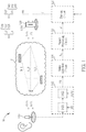
- FIG. 1 is a schematic diagram of a sound producing system 10 according to an embodiment of the present application.
- the sound producing system 10 is similar to the sound producing system disclosed in the US Patent Application No. 16/551,685 filed by Applicant.
- the sound producing system 10 may be disposed in a walled-in environment e.g., an office, a living room, an exhibition hall, or inside a vehicle.
- the sound producing system 10 comprises a sound producing apparatus 12 and a sounding circuit 14.
- the sound producing apparatus 12 comprises a sound producing device (SPD) 120, a driving circuit 122 and a signal processing circuit 124.
- the sounding circuit 14 comprises a sensor 140, a filtering circuit 142 and a spike detection circuit 144.
- the SPD 120 is disposed at a sound producing location/point L SP
- the sensor 140 is disposed at a sound constructing location/point L SC .
- the sound constructing location L SC is preferably near an ear of a listener.
- the sound producing apparatus 12 is configured to perform a sound producing operation, in which the SPD 120 produces a pulse array PA, where the pulse array PA is generated corresponding to an input audio signal A, and comprises a plurality of air pulses P.
- the SPD 120 is driven by a driving signal d, generated by the driving circuit 122, to produce the pulse array PA or equivalently the plurality of air pulses P.
- the SPD 120 comprising a membrane 1201, can be realized by the air pulse generating elements or the sound producing devices disclosed in Application No. 16/125,761 , No. 16/172,876 , No. 16/161,097 , No. 16/368,870 and No.
- the SPD 120 may be a MEMS (micro electrical mechanical system) device.
- the plurality of air pulses P and the air pulse array PA, caused by the membrane vibration and produced by the SPD 120, would inherit the air pulse characteristics disclosed in US Application No.16/125,761 , in which the plurality of air pulses P has an air pulse rate (e.g., 40 KHz) higher than a maximum human audible frequency, and each one of the plurality of air pulses P generated by the SPD 120 would have non-zero offset in terms of sound pressure level (SPL), where the non-zero offset is a deviation from a zero SPL.
- SPL sound pressure level
- the plurality of air pulses P generated by the SPD 120 is aperiodic over a plurality of pulse cycles. Details of the "non-zero SPL offset" and the “aperiodicity" properties may be referred to US Application No.16/125,761 , and details of the device 120 may be referred to the applications listed in the above, which are not narrated herein for brevity.
- the driving circuit 122 receives the input audio signal A and a channel-shaping signal g and generates the driving signal d.
- the signal processing circuit 124 is configured to perform a signal processing operation, e.g., a time reversing operation, on the estimated channel impulse response (CIR) h S (or h S ( t )) of a multipath channel h, so as to generate the channel-shaping signal g.
- the multipath channel h is between the sound producing location L SP and the sound constructing location L SC , and comprises a plurality of channel paths h_0,...h_L.
- the signal processing circuit 124 would generate the channel-shaping signal g such that the channel-shaping signal g(t) is proportional to a time-reversed or a time-reversed-and-conjugated counterpart of the estimated CIR h S ( t ) of the channel h. That is, the channel-shaping signal g(t) reflects the feature/waveform of h S (- t ) or h S *(- t ), regardless of translation in time, where ( )* denotes a complex conjugate operation.
- T may be greater than or equal to the maximum propagation delay of the channel h.
- the SPD 120 and the sounding circuit 14 form a sounding system 11, which can be viewed that the sounding system 11 is integrated in/into the sound producing system 10.
- the sounding system 11 or the sounding circuit 14 is configured to perform a sounding operation on the multipath channel h, i.e., to generate the estimated CIR h S for the sound producing apparatus 12 or for the signal processing circuit 124, such that a time reversal transmission can be performed.
- a sound pressure level (SPL) envelop of a received pulse array RPA, perceived at the sound constructing location L SC and by the listener, is re-constructed or constructed as the input audio signal A(t) at the sound constructing location L SC , given the estimated CIR h S is provided by the sounding circuit 14 to the signal processing circuit 124.
- SPL sound pressure level
- the device 120 is physically disposed at the sound producing location L SP and the sensor 140 is physically disposed at the sound constructing location L SC .
- the rest of the circuits such as the filtering circuit 142, the spike detection circuit 144, the signal processing circuit 124 and the driving circuit 122, can be disposed at any location, not limited to the sound producing location L SP and the sound constructing location L SC , which are illustrated in dashed line in FIG. 1 .
- the pulse generating device 120 receives a sounding sequence SS, and is configured to produce a sounding pulse array SPA according to the sounding sequence SS.
- the sounding pulse array SPA comprises a plurality of sounding pulse SP, and each sounding pulse SP may have (or be corresponding to) a sounding pulse waveform UPW (which can be expressed as p( t )), where the sounding pulse waveform UPW may be determined by the hardware characteristic of the pulse generating device 120.
- the plurality of sounding pules SP and/or the sounding pulse array SPA, corresponding the sounding sequence SS, is produced by the pulse generating device 120 and emitted from the sound producing location L SP , propagates through the multipath channel h, and arrives at the sound constructing location L SC , such that the sensor 140 would receive a received sounding pulse array RSPA corresponding to the sounding pulse array SPA, in terms of SPL.
- the received sounding pulse array RSPA comprises a plurality of received sounding pulses RSP.
- the sensor 140 would convert the received sounding pulse array RSPA in terms of SPL into electric signal.
- a signal component corresponding to the received sounding pulse array RSPA within an output of the sensor 140 is also called as the received sounding pulse array RSPA.
- the sounding sequence SS is a pseudo random sequence or a low auto-correlation sequence, which implies that a correlation of the sounding sequence SS and a time-shifted version of the sounding sequence SS (called an auto-correlation of the sounding sequence SS in the present application) is low, i.e., less than a first threshold, where the first threshold may be 1% of an energy of the sounding sequence (SS).
- the sounding sequence SS is expressed as SS[n] in discrete time sequence, and SS[n-k] represents the time-shifted version of the sounding sequence SS, where n and k denote time index and delay index, respectively.
- the sounding sequence SS satisfies that the correlation between SS[n] and SS[n-k], denoted as ⁇ SS[n], SS[n-k]>, is less than the first threshold.
- the sounding sequence SS may be generated via a quality check process.
- the quality check process is to make sure that the auto-correlation of the sounding sequence SS is sufficiently low.
- the sequence element s m may be corresponding to a binary value, e.g., s m ⁇ ⁇ +1, -1 ⁇ , or a ternary value, e.g., s m ⁇ ⁇ +1, 0, -1 ⁇ .
- the quality check process is not limited. For example, the quality check may be determining whether "a time gap between two successive corresponding sounding pulses ⁇ 16 ⁇ s (microsecond)", "a number of successive sequence elements with same polarity ⁇ 3", "a number of positive sequence element equals a number of negative sequence element ⁇ 1", etc.
- the sounding sequence SS may comprise 2048 sequence elements corresponding to the set of ⁇ +1, -1 ⁇ .
- the 2048 corresponding sounding pules SP comprising 1024 positive sounding pulses SP and 1024 negative sounding pulses SP, are scattered/distributed over a time span of 32.768ms (millisecond), and a time gap between two peaks of two consecutive sounding pules SP is 16 ⁇ s.
- the sounding sequence SS may comprise 384 positive sequence elements with values corresponding to +1, 384 negative sequence elements with values corresponding to -1, and the rest sequence elements with values corresponding to 0.
- the corresponding 768 sounding pules SP are distributed pseudo randomly among 8192 (8K) possible time ticks, where the gap between successive time ticks is 4 ⁇ s and the total time span of the 16k time-ticks is 32.768ms.
- the sounding sequence SS may be realized by the well-developed pseudo-noise (PN) sequence, which is widely exploited in CDMA (code divisional multiple access) communication systems or DSSS (direct-sequence spread spectrum) communication systems.
- PN pseudo-noise
- CDMA code divisional multiple access
- DSSS direct-sequence spread spectrum
- the PN sequence is famous about its low auto-correlation and orthogonality between two distinct PN sequences, which can be easily generated by a low complexity linear-feedback shift register (LFSR). Details of the PN sequence are known by the art, which is not narrated herein.
- the filtering circuit 142 is coupled to the sensor 140, configured to receive the received sounding pulse array RSPA as the electric signal, perform a filtering operation on the received sounding pulse array RSPA, and generate an overall filtering result FR.
- the filtering operation of the filtering circuit 142 is performed according to the low auto-correlation sounding sequence SS and also the sounding pulse waveform UPW.
- the filtering circuit 142 may comprise a first filter 1421 and a second filter 1422.
- the first filter 1421 may be a finite impulse response (FIR) filter with integer coefficients.
- the first filter 1421 is configured to perform a sequence level filtering operation, and a first impulse response H1[n] of the first filter 1421 comprises a component which is proportional to a time-reversed or a time-reversed-and-conjugated version of the sounding sequence SS.
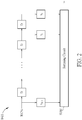
- FIG. 2 is a schematic diagram of the first filter 1421 according to an embodiment of the present application.
- the first filter 1421 has the same circuit topology as a typical FIR filter, comprising (M-1) delay elements D and a summing circuit SUM.
- the first filter 1421 has a plurality of first coefficients c 0 ,...,c M , which would be corresponding to the sequence elements s 0 ,...,s M .
- the first coefficient c 0 ,...,c M may be in a set of ⁇ +1, -1 ⁇ or in a set of ⁇ +1, 0, -1 ⁇ , no multiplication/multiplicator is needed.
- the first filter 1421 may be realized by simplified FIR circuit which comprises no multiplier, but only delay elements and adders.
- the second filter 1422 may be also a finite impulse response (FIR) filter with floating point filter coefficients, meaning that second filter coefficients of the second filter 1422 are in a floating point format. Compared to the first filter 1421, the second filter 1422 has much finer granularity in temporal delay and in coefficient amplitude.
- the second filter 1422 is configured to perform a waveform level filtering operation, and a second impulse response of the second filter 1422, expressed as H2(t), comprises a component which is proportional to a time-reversed or a time-reversed-and-conjugated version of the sounding pulse waveform UPW.
- T cycle represents the pulse cycle of the sounding pulse waveform UPW, and a reciprocal of the pulse cycle T cycle is higher than a maximum human audible frequency.
- the pulse cycle T cycle may be 25 ⁇ s, which is corresponding to a pulse rate of 40 KHz.
- the filtering operation of the filtering circuit 142 may be regarded as a match-filtering operation, which matched to the component sounding pules SP that makes up the sounding sequence SS and the sounding pulse waveform corresponding to SP is UPW That is, an impulse response H( t ) of the filtering circuit 142 comprises a component which is proportional to a time-reversed or a time-reversed-and-conjugated version of the sounding pulse array SPA.
- the output signal of the sensor 140 comprises the component corresponding to the received sounding pulse array RSPA (or corresponding to the sounding sequence SS)
- a spike would appear in the overall filtering result FR of the filtering circuit 142, and the spike is corresponding to one channel path h_ l within the multipath channel h.
- the overall filtering result FR of the filtering circuit 142 would comprise a plurality of spikes, which may be corresponding to the plurality of channel paths h_0,..,h_L. If the output signal of the sensor 140 comprises no component corresponding to the sounding sequence SS, then no spike would appear in the overall filtering result FR, and the overall filtering result FR without spikes can be treated as noise.
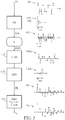
- FIG. 3 illustrates waveforms of the sounding sequence SS, the sounding pulse waveform UPW/p( t ), the sounding pulse array SPA, the first impulse response H1[n] of the first filter 1421, the second impulse response H2(t) of the second filter 1422, the overall filtering result FR output from the filtering circuit 142 and the estimated CIR h S output from the spike detection circuit 144.
- the sounding pulse waveform UPW/p( t ) the sounding pulse array SPA
- the sounding pulse array SPA is corresponding to the sounding sequence SS.
- the first impulse response H1[n] is the time-reversed version of the sounding sequence SS, and the second impulse response H2(t) is the time-reversed version of the sounding pulse waveform UPW.
- the overall filtering result FR would comprise a plurality of spikes. After spike detection, the estimated CIR h S is obtained.
- the pulse array PA generated according to the input audio signal A(t) comprising no component corresponding to the sounding sequence SS.
- the received pulse array RPA corresponding to the pulse array PA (or corresponding to the input audio signal A( t )) would be deconstructed or scrambled after passing through the filtering circuit 142.
- filtering result corresponding to the received pulse array RPA of the input audio signal A(t) would comprise no spike, and would be treated as noise and eliminated by the spike detection circuit 144. Therefore this portion of the (received) pulse array (R)PA would have no impact on the sounding operation.
- the sounding pulse array SPA can be superimposed on the pulse array PA and transmitted concurrently with the pulse array PA.
- the sounding system 11 transmits the plurality of sounding pulses SP for each sounding operation, where the plurality of sounding pulses SP is generated according to the sounding sequence SS with low auto-correlation and low cross-correlation in multi-L SC scenarios. Since the (received) pulse array (R)PA corresponding to the input audio signal A( t )) comprises no component related to the sounding sequence SS, the (received) pulse array (R)PA would have no impact on the sounding operation. In this case, the sound producing operation and the sounding operation can be performed concurrently.
- the listener does not have to wait until the channel probing phase is expired.
- the sounding operation can be performed while the listener listens to music or audio content (which is corresponding to the input audio signal A( t )).
- the sound producing point L SP and the sound constructing point L SC do not have to be fixed location. Both of the sound producing point L SP and the sound constructing point L SC can be time varying. For example, the sound constructing point L SC can vary/move as the listener walks around the environment.
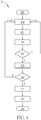
- FIG. 4 is a schematic diagram of the spike detection process 20 according to an embodiment of the present application. As illustrated in FIG. 4 , the spike detection process 20 comprises the following step:
- the overall filtering result FR may be converted into or sampled as a plurality of samples D 0 ,..., D SL-1 .
- t TOT , FR(t) is a continuous time function representing the overall filtering result FR, and SL represents a sample length of the samples D 0 ,..., D SL-1 .
- the spike detection circuit 144 obtains an observation time window W i .
- the observation time window W i may be represented by a set of time indices.
- the time index i is corresponding to the time instant (i ⁇ TS + TOT).
- the observation time window W i has a specific window width (2-r+1), where a parameter r is configured to determine the window width.
- the spike detection circuit 144 obtains a maximum absolute-sample max j ⁇ Wi D j
- the maximum absolute-sample max j ⁇ Wi D j satisfies that max j ⁇ Wi D j ⁇
- W i ⁇ i-r,...,i,...,i+r ⁇
- the maximum absolute-sample max j ⁇ Wi D j is a maximum of a plurality of absolute-samples
- is an absolute value of the sample D j among the plurality of second samples D i-r ,...,D i+r .
- the spike detection circuit 144 determines whether the absolute-sample
- the list LST should comprise a plurality of pairs, denoted as PR pairs (D p , t p ), where PR represents a number of pairs within the list LST.
- the spike detection circuit 144 selects the CL pairs (D p,(S) , t p,(S) ) with the corresponding absolute-samples
- CL represents a number of channel path of the estimated CIR h S ( t ).
- the spike detection circuit 144 may perform a sorting operation on all of the absolute-samples
- is larger than an (or any) unselected absolute-sample
- FIG. 5 is a schematic diagram of waveforms of the samples D i (before the spike detection process 20 is performed) and the estimated CIR h S (after the spike detection process 20 is performed).
- the samples D 7 , D 9 , D 49 , D 51 , D 52 , D 69 , D 71 would be discarded by performing Step 208 as they are not local maximum, and the samples D 30 ,...,D 37 would be discarded by performing Step 214 as they are not sufficiently significant.
- the estimated CIR h S can be formed (at least) by the selected pairs (D 8 , t 8 ), (D 50 , t 50 ) and (D 70 , t 70 ).
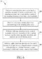
- the sounding process 30 comprises:
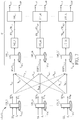
- FIG. 7 is a schematic diagram of a sounding system 41 according to an embodiment of the present application.
- the sounding system 41 comprises a sounding circuit 44 and a plurality of SPDs 120_1,...,120_N, disposed at a plurality of sound producing locations L SP,1 ,..., L SP,N , respectively.
- Each SPD 120_n can be realized by the SPD 120.
- the membrane within the SPD is omitted for brevity.
- the sounding circuit 44 comprises a plurality of sensors 140_1,...,140_M, disposed at a plurality of sound constructing locations L SC,1 ,...,L SC,M , respectively.
- the sounding circuit 44 may also comprise a plurality of filtering circuits 142_1,..., 142_m and a plurality of spike detection circuits 144_1,...,144_M, which are coupled to the plurality of sensors 140_1,...,140_M, respectively.
- a plurality of channels h 1,1 ,...,h 1,N ,....,h m,1 ,...,h m,N ,h M,1 ,..., h M,N is formed.
- Each channel h m,n is a multipath channel.
- Each SPD 120_n receives a sounding sequence SS n and produces a sounding pulse array SPA n according to the sounding sequence SS n .
- the plurality of SPDs 120_1,...,120_N receives a plurality of sounding sequences SS 1 ,...,SS N and produces a plurality of sounding pulse arrays SPA 1 ,..., SPA N , according to the plurality of sounding sequences SS 1 ,...,SS N .
- the sounding sequences SS 1 ,...,SS N may have low cross-correlation, meaning that a correlation between a first sounding sequence SS n1 and a second sounding sequence SS n2 would be less than a second threshold.
- the second threshold may be, e.g., 1% of an energy of the sounding sequence.
- the sounding sequences SS 1 ,...,SS N may be realized by the PN sequence, where a plurality of PN sequences is mutually orthogonal.
- Each sensor 140_m may receive an aggregated received sounding pulse array RSPA (A),m .
- the aggregated received sounding pulse array RSPA (A),m received at the sensor 140_m, is an aggregation of the plurality of sounding pulse arrays SPA 1 ,..., SPA N due to the channels h m,1 ,..., h m,N . That is, the aggregation is naturally performed by the channels h m,1 ,..., h m,N .
- the aggregated received sounding pulse array RSPA (A),m comprises a component which can be expressed as h m,1 ⁇ SPA 1 + ... + h m,N ⁇ SPA N .
- the filtering circuit 142_m may perform a plurality of (overall) filtering operations on the aggregated received sounding pulse array RSPA (A),m , and generate a plurality of overall filtering results FR m,1 ,...,FR m,N .
- FIG. 8 is a schematic diagram of the filtering circuit 142_m according to an embodiment of the present application.
- the filtering circuit 142_m comprises a plurality of first filters 1421_m_1,...,1421_m_N and a plurality of second filter filters 1422.
- Each first filter 1421_m_n among the plurality of first filters 1421_m_1,..., 1421_m_N, may perform a sequence-level filtering operation (similar to the first filter 1421) on the aggregated received sounding pulse array RSPA (A),m according to the sounding sequence SS 1 , and the corresponding second filter 1422 may perform a waveform-level filtering operation (similar to the second filter 1422) on an output of the first filter 1421_m_n according to the sounding pulse waveform UPW. Therefore, the filtering circuit 142_m can generate the plurality of overall filtering results FR m,1 ,...,FR m,N .
- the spike detection circuit 144_m can generate estimated CIRs h S,m,1 ,..., h S,m,N .
- the estimated CIRs h S,1,1 ,..., h S,1,N , ....,h S,m,1 ,...,h S,m,N, h S,M,1 ,..., h S,M,N the different sound producing locations and the difference sound constructing locations can be generated concurrently.
- the plurality of the sequence-level filtering operations is performed parallelly, by the first filter filters 1421_m_1,..., 1421_m_N, which is not limited thereto.
- the sounding circuit may perform the plurality of the sequence-level filtering operations serially (or sequentially), which is also within the scope of the present application.
- the plurality of first filter filters 1421_m_1,..., 1421_m_N and the plurality of second filter filters 1422 are functionally distinguished, the plurality of first filters 1421_m_1,..., 1421_m_N and/or the plurality of second filter filters 1422 may be integrated in different realization.
- the plurality of sounding pulse arrays SPA 1 ,..., SPA N would not interfere with each other when performing the sounding operation, the plurality of sounding pulse arrays SPA 1 ,..., SPA N can be transmitted concurrently.
- FIG.7 can also be regarded as a portion of a sound producing system 40, where the driving circuit(s) and the signal processing circuit(s) of the sound producing system 40 are omitted, and only the SPDs 120_1,...,120_N and the sounding circuit 44 (with details therein) are illustrated. It can be regarded that the sounding system 41 is integrated into the sound producing system 40, in which the sound producing operation is performed.
- the SPDs 120_1,...,120_N receive a plurality of driving signals d 1 ,..., d N to produce a plurality of pulse arrays PA 1 ,..., PA N , respectively. Since the plurality of pulse arrays PA 1 ,..., PA N would not affect the sounding operation, the sounding pulse array SPA n for the sounding operation can be imposed on the pulse array PA n for the sound producing operation. Thus, the pulse arrays PA 1 ,..., PA N and the sounding pulse arrays SPA 1 ,..., SPA N can be transmitted concurrently.
- the sounding system 11 is a single-SPD single-sensor sounding system
- the sounding system 41 is a multi-SPD multi-sensor sounding system. Based on the rationale behind the sounding systems 11 and 41, the sounding system 41 can be degenerated to a single-SPD multi-sensor sounding system or a multi-SPD single-sensor sounding system.
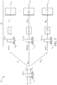
- FIG. 9 is a schematic diagram of a sounding system 51 according to an embodiment of the present application.
- the sounding system 51 is similar to the sounding systems 11 and 41. Different from the sounding systems 11 and 41, the sounding system 51 is a single-SPD multi-sensor sounding system.
- the sounding system 51 comprises a sounding circuit 54 and a SPD 520_n disposed at a sound producing location L SP,n .
- the sounding circuit 54 comprises a plurality of sensors 540_1,...,540_M, a plurality of filtering circuits 542_1,..., 542_M and a plurality of spike detection circuits 544_1,...,544_M.
- the sensors 540_1,...,540_M are disposed at a plurality of sound constructing locations L SC,1 ,..., L SC,M and receives received sounding pulse array RSPA 1 ,.. RSPA M , respectively.
- the filtering circuits 542_1,..., 542_M have similar structure as the filtering circuit 142, where the sequence level filtering operations of the filtering circuits 542_1,..., 542_M are performed according to the sounding sequence SS n received by the SPD 520_n, such that the filtering circuits 542_1,..., 542_M produce overall filtering results FR 1,n ,.. FR M,n .
- the spike detection circuits 544_1,...,544_M have similar structure as the spike detection circuit 144.
- the spike detection circuits 544_1,...,544_M generates estimated CIRs h S,1,n ,..., h S,M,n according to the overall filtering results FR 1,n, ..., FR M,n . Hence, the sounding operation for the channels h 1,n ,..., h M,n can be performed concurrently.
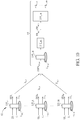
- FIG. 10 is a schematic diagram of a sounding system 61 according to an embodiment of the present application. Different from the sounding systems 11 and 41, the sounding system 61 is a multi-SPD single-sensor sounding system. Operation details of the sounding system 61 are similar to which of the sounding systems 11 and 41, which is not narrated herein for brevity.
- the present application utilizes the sounding sequence with low auto-correlation to produce the sounding pulse array.
- the sounding pulse array for the sounding operation would not be affected by the pulse array, which is intended for the sound producing operation and generated according to the input audio signal.
- the sounding pulse array for the sounding operation can be superimposed on the pulse array for the sound producing operation and transmit concurrently with the pulse array for the sound producing operation.
- the present application utilizes the plurality of sounding sequences with low cross-correlation to produce the plurality of sounding pulse arrays from different SPDs, or from one SPD to multiple sound construction locations.
- the sounding pulse arrays (for the sounding operation) and the pulse arrays (for the sound producing operation) can be transmitted concurrently, the plurality of CIRs between the different sound producing locations and the difference sound constructing locations can be generated concurrently.
Landscapes
- Engineering & Computer Science (AREA)
- Physics & Mathematics (AREA)
- Acoustics & Sound (AREA)
- Signal Processing (AREA)
- Health & Medical Sciences (AREA)
- Otolaryngology (AREA)
- General Health & Medical Sciences (AREA)
- Multimedia (AREA)
- Measurement Of Mechanical Vibrations Or Ultrasonic Waves (AREA)
- Stereophonic System (AREA)
- Electrophonic Musical Instruments (AREA)
- Measuring Pulse, Heart Rate, Blood Pressure Or Blood Flow (AREA)
Applications Claiming Priority (2)
| Application Number | Priority Date | Filing Date | Title |
|---|---|---|---|
| US201962828483P | 2019-04-03 | 2019-04-03 | |
| US16/583,282 US10623882B1 (en) | 2019-04-03 | 2019-09-26 | Sounding system and sounding method |
Publications (2)
| Publication Number | Publication Date |
|---|---|
| EP3719794A1 true EP3719794A1 (fr) | 2020-10-07 |
| EP3719794B1 EP3719794B1 (fr) | 2022-11-23 |
Family
ID=70223625
Family Applications (1)
| Application Number | Title | Priority Date | Filing Date |
|---|---|---|---|
| EP19203996.4A Active EP3719794B1 (fr) | 2019-04-03 | 2019-10-18 | Système audio |
Country Status (4)
| Country | Link |
|---|---|
| US (1) | US10623882B1 (fr) |
| EP (1) | EP3719794B1 (fr) |
| KR (1) | KR102216596B1 (fr) |
| CN (1) | CN111800711B (fr) |
Families Citing this family (5)
| Publication number | Priority date | Publication date | Assignee | Title |
|---|---|---|---|---|
| US10681488B1 (en) * | 2019-03-03 | 2020-06-09 | xMEMS Labs, Inc. | Sound producing apparatus and sound producing system |
| WO2022000228A1 (fr) * | 2020-06-30 | 2022-01-06 | Qualcomm Incorporated | Configuration et programmation de signal de détection |
| EP4173372A4 (fr) * | 2020-06-30 | 2024-12-04 | Qualcomm Incorporated | Précodage de détection conjointe et services de communication |
| KR102475665B1 (ko) * | 2020-11-12 | 2022-12-07 | 엑스멤스 랩스 인코포레이티드 | 크로스오버 회로 |
| TWI803124B (zh) | 2021-12-29 | 2023-05-21 | 財團法人工業技術研究院 | 具多重振動部的微機電裝置 |
Citations (4)
| Publication number | Priority date | Publication date | Assignee | Title |
|---|---|---|---|---|
| US6807281B1 (en) * | 1998-01-09 | 2004-10-19 | Sony Corporation | Loudspeaker and method of driving the same as well as audio signal transmitting/receiving apparatus |
| US7146011B2 (en) * | 2001-08-31 | 2006-12-05 | Nanyang Technological University | Steering of directional sound beams |
| US20070211574A1 (en) * | 2003-10-08 | 2007-09-13 | Croft James J Iii | Parametric Loudspeaker System And Method For Enabling Isolated Listening To Audio Material |
| US7596228B2 (en) * | 2002-08-26 | 2009-09-29 | Frank Joseph Pompei | Parametric array modulation and processing method |
Family Cites Families (11)
| Publication number | Priority date | Publication date | Assignee | Title |
|---|---|---|---|---|
| US4515997A (en) * | 1982-09-23 | 1985-05-07 | Stinger Jr Walter E | Direct digital loudspeaker |
| GB9506725D0 (en) * | 1995-03-31 | 1995-05-24 | Hooley Anthony | Improvements in or relating to loudspeakers |
| WO2004047490A1 (fr) * | 2002-11-15 | 2004-06-03 | Sony Corporation | Procédé et dispositif de traitement de signal audio |
| JP3821228B2 (ja) | 2002-11-15 | 2006-09-13 | ソニー株式会社 | オーディオ信号の処理方法および処理装置 |
| GB0301093D0 (en) * | 2003-01-17 | 2003-02-19 | 1 Ltd | Set-up method for array-type sound systems |
| US8116465B2 (en) * | 2004-04-28 | 2012-02-14 | Sony Corporation | Measuring apparatus and method, and recording medium |
| CN103765920B (zh) * | 2011-08-16 | 2017-03-01 | 英派尔科技开发有限公司 | 用于生成音频信号的技术 |
| US10129640B2 (en) * | 2014-02-06 | 2018-11-13 | Hewlett-Packard Development Company, L.P. | Suppressing a modal frequency of a loudspeaker |
| EP3079375A1 (fr) * | 2015-04-10 | 2016-10-12 | Fraunhofer-Gesellschaft zur Förderung der angewandten Forschung e.V. | Reproduction acoustique différentielle |
| WO2017072118A1 (fr) * | 2015-10-26 | 2017-05-04 | Fraunhofer-Gesellschaft zur Förderung der angewandten Forschung e.V. | Appareil et procédé pour générer un signal audio filtré exécutant une restitution d'élévation |
| US10367430B2 (en) | 2016-01-11 | 2019-07-30 | Infineon Technologies Ag | System and method for a variable flow transducer |
-
2019
- 2019-09-26 US US16/583,282 patent/US10623882B1/en active Active
- 2019-10-18 EP EP19203996.4A patent/EP3719794B1/fr active Active
- 2019-11-19 KR KR1020190148352A patent/KR102216596B1/ko active Active
-
2020
- 2020-02-18 CN CN202010100568.6A patent/CN111800711B/zh active Active
Patent Citations (4)
| Publication number | Priority date | Publication date | Assignee | Title |
|---|---|---|---|---|
| US6807281B1 (en) * | 1998-01-09 | 2004-10-19 | Sony Corporation | Loudspeaker and method of driving the same as well as audio signal transmitting/receiving apparatus |
| US7146011B2 (en) * | 2001-08-31 | 2006-12-05 | Nanyang Technological University | Steering of directional sound beams |
| US7596228B2 (en) * | 2002-08-26 | 2009-09-29 | Frank Joseph Pompei | Parametric array modulation and processing method |
| US20070211574A1 (en) * | 2003-10-08 | 2007-09-13 | Croft James J Iii | Parametric Loudspeaker System And Method For Enabling Isolated Listening To Audio Material |
Also Published As
| Publication number | Publication date |
|---|---|
| EP3719794B1 (fr) | 2022-11-23 |
| CN111800711B (zh) | 2021-09-28 |
| US10623882B1 (en) | 2020-04-14 |
| KR20200117828A (ko) | 2020-10-14 |
| KR102216596B1 (ko) | 2021-02-16 |
| CN111800711A (zh) | 2020-10-20 |
Similar Documents
| Publication | Publication Date | Title |
|---|---|---|
| EP3719794B1 (fr) | Système audio | |
| CA2818775C (fr) | Sequences de zone de correlation nulle pour un systeme de communication | |
| CN101150346B (zh) | 一种接收机 | |
| WO2007100330A1 (fr) | Systèmes et procédés de séparation aveugle de signaux sources | |
| CA2818766C (fr) | Sequences de zone de correlation nulle pour un systeme de communication | |
| Sabra et al. | Blind deconvolution in ocean waveguides using artificial time reversal | |
| EP1562403B1 (fr) | Procédé et dispositif de traitement de signal audio | |
| US10681488B1 (en) | Sound producing apparatus and sound producing system | |
| Tohyama | Sound in the time domain | |
| Hahn et al. | Identification of dynamic acoustic systems by orthogonal expansion of time-variant impulse responses | |
| CN107533840B (zh) | 声学扩散歧管 | |
| Healya et al. | Full-duplex channel analysis for underwater acoustic communications | |
| Chua et al. | A low latency approach for blind source separation | |
| RU2548660C2 (ru) | Приемное устройство широкополосных сигналов | |
| JP2016537866A (ja) | 複雑さの観点から最適化された、空間効果を伴う音響空間化 | |
| WO2004086557A3 (fr) | Procede pour determiner des reponses impulsionnelles d’un milieu vis-à-vis de la transmission d’ondes entre differents points | |
| Chua et al. | Non-iterative impulse response shortening method for system latency reduction | |
| CN102741920B (zh) | 利用编码和最大长度级序列的用于立体声和环绕声的音频信号去相关 | |
| Keele Jr | Time-Frequency Display of Electroacoustic Data Using Cycle-Octave Wavelet Transforms | |
| JP5113063B2 (ja) | データ送信方法、データ送信装置、データ受信装置、符号語セットの作成方法及び移動通信方法 | |
| CN101833107B (zh) | 可控震源的处理方法及其装置 | |
| Zhou et al. | An underwater acoustic communications scheme with inherent scale diversity for multiple users | |
| CN115174333A (zh) | 适用于urllc场景下极简信号收发方法 | |
| Daigle et al. | An FFT-Based Algorithm for Acoustic Measurements Using Coded Signals | |
| JP6482117B2 (ja) | 信号処理装置及び方法並びに補聴特性の調整方法 |
Legal Events
| Date | Code | Title | Description |
|---|---|---|---|
| PUAI | Public reference made under article 153(3) epc to a published international application that has entered the european phase |
Free format text: ORIGINAL CODE: 0009012 |
|
| STAA | Information on the status of an ep patent application or granted ep patent |
Free format text: STATUS: THE APPLICATION HAS BEEN PUBLISHED |
|
| AK | Designated contracting states |
Kind code of ref document: A1 Designated state(s): AL AT BE BG CH CY CZ DE DK EE ES FI FR GB GR HR HU IE IS IT LI LT LU LV MC MK MT NL NO PL PT RO RS SE SI SK SM TR |
|
| AX | Request for extension of the european patent |
Extension state: BA ME |
|
| STAA | Information on the status of an ep patent application or granted ep patent |
Free format text: STATUS: REQUEST FOR EXAMINATION WAS MADE |
|
| 17P | Request for examination filed |
Effective date: 20201110 |
|
| RBV | Designated contracting states (corrected) |
Designated state(s): AL AT BE BG CH CY CZ DE DK EE ES FI FR GB GR HR HU IE IS IT LI LT LU LV MC MK MT NL NO PL PT RO RS SE SI SK SM TR |
|
| GRAP | Despatch of communication of intention to grant a patent |
Free format text: ORIGINAL CODE: EPIDOSNIGR1 |
|
| STAA | Information on the status of an ep patent application or granted ep patent |
Free format text: STATUS: GRANT OF PATENT IS INTENDED |
|
| RIC1 | Information provided on ipc code assigned before grant |
Ipc: H04S 7/00 20060101ALI20220518BHEP Ipc: H04R 3/12 20060101ALI20220518BHEP Ipc: H04R 1/40 20060101ALI20220518BHEP Ipc: H04R 29/00 20060101ALI20220518BHEP Ipc: G10K 15/02 20060101AFI20220518BHEP |
|
| INTG | Intention to grant announced |
Effective date: 20220620 |
|
| RAP3 | Party data changed (applicant data changed or rights of an application transferred) |
Owner name: XMEMS LABS, INC. |
|
| GRAS | Grant fee paid |
Free format text: ORIGINAL CODE: EPIDOSNIGR3 |
|
| GRAA | (expected) grant |
Free format text: ORIGINAL CODE: 0009210 |
|
| STAA | Information on the status of an ep patent application or granted ep patent |
Free format text: STATUS: THE PATENT HAS BEEN GRANTED |
|
| AK | Designated contracting states |
Kind code of ref document: B1 Designated state(s): AL AT BE BG CH CY CZ DE DK EE ES FI FR GB GR HR HU IE IS IT LI LT LU LV MC MK MT NL NO PL PT RO RS SE SI SK SM TR |
|
| REG | Reference to a national code |
Ref country code: GB Ref legal event code: FG4D |
|
| REG | Reference to a national code |
Ref country code: CH Ref legal event code: EP |
|
| REG | Reference to a national code |
Ref country code: AT Ref legal event code: REF Ref document number: 1533637 Country of ref document: AT Kind code of ref document: T Effective date: 20221215 Ref country code: DE Ref legal event code: R096 Ref document number: 602019022171 Country of ref document: DE |
|
| REG | Reference to a national code |
Ref country code: IE Ref legal event code: FG4D |
|
| REG | Reference to a national code |
Ref country code: LT Ref legal event code: MG9D |
|
| REG | Reference to a national code |
Ref country code: NL Ref legal event code: MP Effective date: 20221123 |
|
| REG | Reference to a national code |
Ref country code: AT Ref legal event code: MK05 Ref document number: 1533637 Country of ref document: AT Kind code of ref document: T Effective date: 20221123 |
|
| PG25 | Lapsed in a contracting state [announced via postgrant information from national office to epo] |
Ref country code: SE Free format text: LAPSE BECAUSE OF FAILURE TO SUBMIT A TRANSLATION OF THE DESCRIPTION OR TO PAY THE FEE WITHIN THE PRESCRIBED TIME-LIMIT Effective date: 20221123 Ref country code: PT Free format text: LAPSE BECAUSE OF FAILURE TO SUBMIT A TRANSLATION OF THE DESCRIPTION OR TO PAY THE FEE WITHIN THE PRESCRIBED TIME-LIMIT Effective date: 20230323 Ref country code: NO Free format text: LAPSE BECAUSE OF FAILURE TO SUBMIT A TRANSLATION OF THE DESCRIPTION OR TO PAY THE FEE WITHIN THE PRESCRIBED TIME-LIMIT Effective date: 20230223 Ref country code: LT Free format text: LAPSE BECAUSE OF FAILURE TO SUBMIT A TRANSLATION OF THE DESCRIPTION OR TO PAY THE FEE WITHIN THE PRESCRIBED TIME-LIMIT Effective date: 20221123 Ref country code: FI Free format text: LAPSE BECAUSE OF FAILURE TO SUBMIT A TRANSLATION OF THE DESCRIPTION OR TO PAY THE FEE WITHIN THE PRESCRIBED TIME-LIMIT Effective date: 20221123 Ref country code: ES Free format text: LAPSE BECAUSE OF FAILURE TO SUBMIT A TRANSLATION OF THE DESCRIPTION OR TO PAY THE FEE WITHIN THE PRESCRIBED TIME-LIMIT Effective date: 20221123 Ref country code: AT Free format text: LAPSE BECAUSE OF FAILURE TO SUBMIT A TRANSLATION OF THE DESCRIPTION OR TO PAY THE FEE WITHIN THE PRESCRIBED TIME-LIMIT Effective date: 20221123 |
|
| PG25 | Lapsed in a contracting state [announced via postgrant information from national office to epo] |
Ref country code: RS Free format text: LAPSE BECAUSE OF FAILURE TO SUBMIT A TRANSLATION OF THE DESCRIPTION OR TO PAY THE FEE WITHIN THE PRESCRIBED TIME-LIMIT Effective date: 20221123 Ref country code: PL Free format text: LAPSE BECAUSE OF FAILURE TO SUBMIT A TRANSLATION OF THE DESCRIPTION OR TO PAY THE FEE WITHIN THE PRESCRIBED TIME-LIMIT Effective date: 20221123 Ref country code: LV Free format text: LAPSE BECAUSE OF FAILURE TO SUBMIT A TRANSLATION OF THE DESCRIPTION OR TO PAY THE FEE WITHIN THE PRESCRIBED TIME-LIMIT Effective date: 20221123 Ref country code: IS Free format text: LAPSE BECAUSE OF FAILURE TO SUBMIT A TRANSLATION OF THE DESCRIPTION OR TO PAY THE FEE WITHIN THE PRESCRIBED TIME-LIMIT Effective date: 20230323 Ref country code: HR Free format text: LAPSE BECAUSE OF FAILURE TO SUBMIT A TRANSLATION OF THE DESCRIPTION OR TO PAY THE FEE WITHIN THE PRESCRIBED TIME-LIMIT Effective date: 20221123 Ref country code: GR Free format text: LAPSE BECAUSE OF FAILURE TO SUBMIT A TRANSLATION OF THE DESCRIPTION OR TO PAY THE FEE WITHIN THE PRESCRIBED TIME-LIMIT Effective date: 20230224 |
|
| PG25 | Lapsed in a contracting state [announced via postgrant information from national office to epo] |
Ref country code: NL Free format text: LAPSE BECAUSE OF FAILURE TO SUBMIT A TRANSLATION OF THE DESCRIPTION OR TO PAY THE FEE WITHIN THE PRESCRIBED TIME-LIMIT Effective date: 20221123 |
|
| PG25 | Lapsed in a contracting state [announced via postgrant information from national office to epo] |
Ref country code: SM Free format text: LAPSE BECAUSE OF FAILURE TO SUBMIT A TRANSLATION OF THE DESCRIPTION OR TO PAY THE FEE WITHIN THE PRESCRIBED TIME-LIMIT Effective date: 20221123 Ref country code: RO Free format text: LAPSE BECAUSE OF FAILURE TO SUBMIT A TRANSLATION OF THE DESCRIPTION OR TO PAY THE FEE WITHIN THE PRESCRIBED TIME-LIMIT Effective date: 20221123 Ref country code: EE Free format text: LAPSE BECAUSE OF FAILURE TO SUBMIT A TRANSLATION OF THE DESCRIPTION OR TO PAY THE FEE WITHIN THE PRESCRIBED TIME-LIMIT Effective date: 20221123 Ref country code: DK Free format text: LAPSE BECAUSE OF FAILURE TO SUBMIT A TRANSLATION OF THE DESCRIPTION OR TO PAY THE FEE WITHIN THE PRESCRIBED TIME-LIMIT Effective date: 20221123 Ref country code: CZ Free format text: LAPSE BECAUSE OF FAILURE TO SUBMIT A TRANSLATION OF THE DESCRIPTION OR TO PAY THE FEE WITHIN THE PRESCRIBED TIME-LIMIT Effective date: 20221123 |
|
| REG | Reference to a national code |
Ref country code: DE Ref legal event code: R097 Ref document number: 602019022171 Country of ref document: DE |
|
| PG25 | Lapsed in a contracting state [announced via postgrant information from national office to epo] |
Ref country code: SK Free format text: LAPSE BECAUSE OF FAILURE TO SUBMIT A TRANSLATION OF THE DESCRIPTION OR TO PAY THE FEE WITHIN THE PRESCRIBED TIME-LIMIT Effective date: 20221123 Ref country code: AL Free format text: LAPSE BECAUSE OF FAILURE TO SUBMIT A TRANSLATION OF THE DESCRIPTION OR TO PAY THE FEE WITHIN THE PRESCRIBED TIME-LIMIT Effective date: 20221123 |
|
| PLBE | No opposition filed within time limit |
Free format text: ORIGINAL CODE: 0009261 |
|
| STAA | Information on the status of an ep patent application or granted ep patent |
Free format text: STATUS: NO OPPOSITION FILED WITHIN TIME LIMIT |
|
| 26N | No opposition filed |
Effective date: 20230824 |
|
| PG25 | Lapsed in a contracting state [announced via postgrant information from national office to epo] |
Ref country code: SI Free format text: LAPSE BECAUSE OF FAILURE TO SUBMIT A TRANSLATION OF THE DESCRIPTION OR TO PAY THE FEE WITHIN THE PRESCRIBED TIME-LIMIT Effective date: 20221123 |
|
| PG25 | Lapsed in a contracting state [announced via postgrant information from national office to epo] |
Ref country code: IT Free format text: LAPSE BECAUSE OF FAILURE TO SUBMIT A TRANSLATION OF THE DESCRIPTION OR TO PAY THE FEE WITHIN THE PRESCRIBED TIME-LIMIT Effective date: 20221123 Ref country code: MC Free format text: LAPSE BECAUSE OF FAILURE TO SUBMIT A TRANSLATION OF THE DESCRIPTION OR TO PAY THE FEE WITHIN THE PRESCRIBED TIME-LIMIT Effective date: 20221123 |
|
| REG | Reference to a national code |
Ref country code: CH Ref legal event code: PL |
|
| REG | Reference to a national code |
Ref country code: BE Ref legal event code: MM Effective date: 20231031 |
|
| PG25 | Lapsed in a contracting state [announced via postgrant information from national office to epo] |
Ref country code: LU Free format text: LAPSE BECAUSE OF NON-PAYMENT OF DUE FEES Effective date: 20231018 |
|
| PG25 | Lapsed in a contracting state [announced via postgrant information from national office to epo] |
Ref country code: LU Free format text: LAPSE BECAUSE OF NON-PAYMENT OF DUE FEES Effective date: 20231018 |
|
| PG25 | Lapsed in a contracting state [announced via postgrant information from national office to epo] |
Ref country code: CH Free format text: LAPSE BECAUSE OF NON-PAYMENT OF DUE FEES Effective date: 20231031 |
|
| PG25 | Lapsed in a contracting state [announced via postgrant information from national office to epo] |
Ref country code: CH Free format text: LAPSE BECAUSE OF NON-PAYMENT OF DUE FEES Effective date: 20231031 |
|
| PG25 | Lapsed in a contracting state [announced via postgrant information from national office to epo] |
Ref country code: BE Free format text: LAPSE BECAUSE OF NON-PAYMENT OF DUE FEES Effective date: 20231031 |
|
| REG | Reference to a national code |
Ref country code: DE Ref legal event code: R082 Ref document number: 602019022171 Country of ref document: DE Representative=s name: STRAUS, ALEXANDER, DIPL.-CHEM.UNIV. DR.PHIL., DE |
|
| PG25 | Lapsed in a contracting state [announced via postgrant information from national office to epo] |
Ref country code: IE Free format text: LAPSE BECAUSE OF NON-PAYMENT OF DUE FEES Effective date: 20231018 |
|
| PG25 | Lapsed in a contracting state [announced via postgrant information from national office to epo] |
Ref country code: IE Free format text: LAPSE BECAUSE OF NON-PAYMENT OF DUE FEES Effective date: 20231018 |
|
| PG25 | Lapsed in a contracting state [announced via postgrant information from national office to epo] |
Ref country code: BG Free format text: LAPSE BECAUSE OF FAILURE TO SUBMIT A TRANSLATION OF THE DESCRIPTION OR TO PAY THE FEE WITHIN THE PRESCRIBED TIME-LIMIT Effective date: 20221123 |
|
| PG25 | Lapsed in a contracting state [announced via postgrant information from national office to epo] |
Ref country code: BG Free format text: LAPSE BECAUSE OF FAILURE TO SUBMIT A TRANSLATION OF THE DESCRIPTION OR TO PAY THE FEE WITHIN THE PRESCRIBED TIME-LIMIT Effective date: 20221123 |
|
| PG25 | Lapsed in a contracting state [announced via postgrant information from national office to epo] |
Ref country code: CY Free format text: LAPSE BECAUSE OF FAILURE TO SUBMIT A TRANSLATION OF THE DESCRIPTION OR TO PAY THE FEE WITHIN THE PRESCRIBED TIME-LIMIT; INVALID AB INITIO Effective date: 20191018 |
|
| PG25 | Lapsed in a contracting state [announced via postgrant information from national office to epo] |
Ref country code: HU Free format text: LAPSE BECAUSE OF FAILURE TO SUBMIT A TRANSLATION OF THE DESCRIPTION OR TO PAY THE FEE WITHIN THE PRESCRIBED TIME-LIMIT; INVALID AB INITIO Effective date: 20191018 |
|
| PGFP | Annual fee paid to national office [announced via postgrant information from national office to epo] |
Ref country code: GB Payment date: 20250827 Year of fee payment: 7 |
|
| PGFP | Annual fee paid to national office [announced via postgrant information from national office to epo] |
Ref country code: FR Payment date: 20250827 Year of fee payment: 7 |
|
| PG25 | Lapsed in a contracting state [announced via postgrant information from national office to epo] |
Ref country code: TR Free format text: LAPSE BECAUSE OF FAILURE TO SUBMIT A TRANSLATION OF THE DESCRIPTION OR TO PAY THE FEE WITHIN THE PRESCRIBED TIME-LIMIT Effective date: 20221123 |
|
| PGFP | Annual fee paid to national office [announced via postgrant information from national office to epo] |
Ref country code: DE Payment date: 20251031 Year of fee payment: 7 |