EP3719963A1 - Flüssigkeitsgekühlter stator für hochleistungsmaschine - Google Patents
Flüssigkeitsgekühlter stator für hochleistungsmaschine Download PDFInfo
- Publication number
- EP3719963A1 EP3719963A1 EP20174454.7A EP20174454A EP3719963A1 EP 3719963 A1 EP3719963 A1 EP 3719963A1 EP 20174454 A EP20174454 A EP 20174454A EP 3719963 A1 EP3719963 A1 EP 3719963A1
- Authority
- EP
- European Patent Office
- Prior art keywords
- stator
- rotary electric
- electric machine
- windings
- winding
- Prior art date
- Legal status (The legal status is an assumption and is not a legal conclusion. Google has not performed a legal analysis and makes no representation as to the accuracy of the status listed.)
- Granted
Links
Images





Classifications
-
- H—ELECTRICITY
- H02—GENERATION; CONVERSION OR DISTRIBUTION OF ELECTRIC POWER
- H02K—DYNAMO-ELECTRIC MACHINES
- H02K3/00—Details of windings
- H02K3/04—Windings characterised by the conductor shape, form or construction, e.g. with bar conductors
- H02K3/24—Windings characterised by the conductor shape, form or construction, e.g. with bar conductors with channels or ducts for cooling medium between the conductors
-
- H—ELECTRICITY
- H02—GENERATION; CONVERSION OR DISTRIBUTION OF ELECTRIC POWER
- H02K—DYNAMO-ELECTRIC MACHINES
- H02K9/00—Arrangements for cooling or ventilating
- H02K9/19—Arrangements for cooling or ventilating for machines with closed casing and closed-circuit cooling using a liquid cooling medium, e.g. oil
- H02K9/197—Arrangements for cooling or ventilating for machines with closed casing and closed-circuit cooling using a liquid cooling medium, e.g. oil in which the rotor or stator space is fluid-tight, e.g. to provide for different cooling media for rotor and stator
-
- Y—GENERAL TAGGING OF NEW TECHNOLOGICAL DEVELOPMENTS; GENERAL TAGGING OF CROSS-SECTIONAL TECHNOLOGIES SPANNING OVER SEVERAL SECTIONS OF THE IPC; TECHNICAL SUBJECTS COVERED BY FORMER USPC CROSS-REFERENCE ART COLLECTIONS [XRACs] AND DIGESTS
- Y10—TECHNICAL SUBJECTS COVERED BY FORMER USPC
- Y10T—TECHNICAL SUBJECTS COVERED BY FORMER US CLASSIFICATION
- Y10T29/00—Metal working
- Y10T29/49—Method of mechanical manufacture
- Y10T29/49002—Electrical device making
- Y10T29/49009—Dynamoelectric machine
Definitions
- the present invention relates generally to electric motors and generators, and in particular to a liquid cooled stator for an electric motor or generator.
- Stators for rotary electric machines including electric motors, generators, and the like have employed various types of cooling including air, liquid and two phase cooling. Air blown through the center of the machine had traditionally been the standard with liquid becoming more common in high power applications. Two phase cooling has not developed into a mainstream due to cost and complexity. Liquid cooling is preferred for many high power applications because it generates a more compact design and is compatible with a sealed housing construction which is preferable in many environments.
- the most common liquid cooling design uses a cooling jacket wrapped around the outside of the stator assembly. This can be seen in U.S. patent 5,448,118 entitled LIQUID COOLED MOTOR AND ITS JACKET, included herein by reference.
- this design there is an aluminum extrusion that surrounds the outside of the stator and has passages for cooling fluid to pass through. This design cools the stator better than air, but is limited by i) the conductivity between the jacket and the stator, ii) the poor conductivity of the stator laminations, iii) the conductivity of the slot liners, and iv) the poor conductivity between the winding and the slot liners.
- This design integrates the cooling manifold into the stator slot directly adjacent to the wires that generate the heat. This accommodates use of standard ethylene glycol coolant which is highly desired in the industry, and achieves very compact machines.
- stator winding type is a distributed winding.
- One type of which is an integer-slot winding wherein the number of slots per pole per phase is an integer.
- An example of this is a 4 pole 12 slot, 3 phase motor.
- the number of slots per pole per phase is 1 and therefore an integer.
- These windings typically require some relatively complex end turns to wire them properly.
- One type of construction is a diamond form winding that is used in many of the larger, higher voltage, and more reliable machines.
- Concentrated windings can be single layer or double layer designs. Single layer designs have windings that are wound only on alternating stator teeth and only apply where there is an even number of stator slots/teeth. Double layer designs have coils wound on every stator tooth.
- each slot has half of one coil and half of another coil going through the slot and the end turns are very short.
- the end turns can be as short as the width of the stator tooth.
- Double layer concentrated windings have the advantage of being a simple coil wrapped around each tooth. For an external rotor configuration, and using relatively open slots, this allows simple assembly of coils. For the more typical internal rotor configuration, assembly is a bit trickier because even with relatively open slots, the opening is smaller than the slot. This is further complicated if the slot opening is made smaller for motor performance reasons.
- a typical method of mitigating this issue is to make the teeth separate to either be able to 1) wind the wire directly on the tooth or 2) slide the winding on from the outside.
- the first method is shown in U.S. patent 5,583,387 entitled STATOR OF DYNAMO-ELECTRIC MACHINE incorporated herein by reference.
- the second method is shown in U.S.
- Rotary electric machines including electric motors, generators, and the like have employed various methods of constructing stator windings. Some methods are applicable to only certain types of stator windings.
- Another common method is diamond form winding.
- This method typically uses rectangular wire with various tapes located between conductors to separate any conductors that are significantly different in voltage and the shape of the coil is in a diamond shape.
- This is a robust winding for higher voltage machines or machines that are prone to partial discharge.
- This is typically the most labor-intensive type of winding due to the manufacture of the coils and the insertion time to put these coils in the machine from the inside. This labor time can be improved by insertion from the outside which is one of the objects of the design disclosed in this patent.
- bobbin layer winding This type of winding places conductors in exact locations for very accurate stacking of wires. This can achieve a high amount of conductors in a small area for high efficiency. This is not typically used for distributed windings because you are not able to bobbin wind a coil and then insert it into a stator assembly. This is possible with concentrated windings that have removable teeth.
- the most common wire to use is round wire but it is possible to use square or rectangular wire. Layer winding with rectangular wire is typically laid flat and wound the easy way. This facilitates simpler winding, but one disadvantage of this is the eddy current losses due to slot leakage can be significantly higher. Also, orientation of the rectangular wire can have an impact on thermal performance and depends on the overall heat removal scheme.
- Layer winding with rectangular wire can be done edge wound (wound the hard way.) This is shown in U.S. patent 4,446,393 entitled DYNAMOELECTRIC FIELD ASSEMBLY AND WINDING THEREFOR incorporated herein by reference. In this patent a single layer of rectangular wire is used in each slot and is edge wound. This patent used removable teeth and an internal rotor.
- U.S. patent application serial number 2010/0066198 filed March 18, 2010 entitled INSERTION OF PREFABRICATED CONCENTRATED WINDINGS INTO STATOR SLOTS incorporated herein by reference also shows a single layer of rectangular wire but does not use removable teeth. Edge wound coils can have significantly lower eddy current losses in the wires. The cooling may be better or worse depending on the overall cooling scheme.
- the machine described herein incorporates several novel construction methods in its stator.
- the key is different approaches to accommodate liquid cooling in the slot in an economical efficient approach.
- the preferred design uses either Edge Form Wound Windings for concentrated wound machines or Diamond Form Wound Windings for distributed wound machines.
- the preferred approach places the cooling manifold in the center of the slot between two sets of windings. In certain applications it makes sense to put at least some of the cooling manifold in different locations in the slot. This general approach insures a very good thermal solution that allows much higher current density in the slot. Higher current density in the slot allows significantly higher overall torque density of the rotating machine.
- the machine described herein also allows the use of conductive fluid such as ethylene glycol.
- This configuration uses metallic vessels that contain the liquid cooling medium for high reliability. These metallic vessels are brazed together into manifolds to efficiently direct the liquid to where the heat is generated. The specific geometry and connectivity of the cooling manifolds allows this to be done without detrimental effects to the performance of the machine.
- a rotary electric machine comprising a stator having a circumaxially spaced series of axially extending teeth defining a similar series of circumaxially spaced winding slots there between.
- a plurality of stator windings are at least partially disposed respectively in the slots, the windings being electrically connected to form a plurality of phases wherein one or more slots contain the same magnitude of current at substantially all times for each phase.
- a means is provided that defines a plurality of elongated coolant passageways disposed respectively in the slots; wherein a subset of coolant passageways contained in the slots for a single phase is an even number and fluid flows in one direction for half of this subset of coolant passageways and in the opposite direction for the other half of this subset of coolant passageways. At least two of the coolant passageways in the whole machine are connected fluidically in parallel; and at least one of the coolant passageway is located circumaxially between two windings.
- the illustrated rotary electric machine has coolant passages that are constructed of an electrically conductive material.
- the coolant is a liquid.
- the coolant passageways are attached using a brazed connection and the slots each have the same number of coolant passageways going in one direction as are going in an opposite direction.
- the coolant passageway is located circumaxially between winding and tooth (of this illustrated embodiment).
- the machine is a distributed wound machine. In another embodiment, the machine is a concentrated wound machine.
- At least some of the coolant passageways are formed by a plurality of generally adjacent structures that are fluidically connected at only one end of the machine.
- a method for building stator assemblies that contain in-slot cooling manifolds and separable teeth.
- the teeth comprise an assembly of stator teeth, in-slot cooling manifolds and windings first, then followed by a step of insertion of an outer yolk assembly in an axial direction, then followed by a step of securing of the standard teeth.
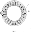
- stator yoke 1 a distributed wound stator assembly is shown containing stator yoke 1, stator coil 2, stator coil 3, and stator lamination teeth 4.
- stator coils 2,3 There are two different stator coils 2,3 shown due to the fact that they are not evenly spaced and therefore are of slightly different shape.
- the coils 2,3 are bent inward on at least one end as shown in Figure 2 where coil ends 2a,3a are bent inward and coil ends 2b,3b are bent in a more conventional configuration.
- the joint between the stator teeth 4 and stator yoke 1 can be seen clearly in Figure 3 .
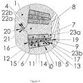
- the coil bundles can be seen as 5,6,7, and 8.
- Each of these coil bundles can be made up of anywhere from a single turn to many turns.
- the wire is rectangular in shape with the wide dimension on the wire being in the circumaxial direction of the machine. This is the same direction as the narrow dimension on the coil bundle as shown in Figure 4 .
- This can be accomplished by forming the coils in a diamond shape as shown in Figure 8 .
- This diamond shape coil has straight sections 38, pin turns 39a and 39b, bends in the easy way 40 and bends in the hard way 41.
- the cooling manifold in each slot consist of 4 cooling bars 9,10,11, and 12 which are manufactured by aluminum extrusion and therefore electrically conductive.
- Aluminum is used for ease of manufacturing and the attachment to the slot manifold can be done using a brazing process.
- Preferably cooling goes down in one slot and up in the other slot in that same cooling bar.
- the cooling bars are separated by insulator 13, 14, and 15 made of a solid insulator such as PPS.
- an insulator 17 Located between cooling bars 9,10,11,12 and coil bundles 5,6 is an insulator 17 that is preferably a thermally conductive electrically insulative material.
- this material preferably is made of a compressible material to accomplish good thermal contact between the cooling bars and the coil bundles.
- a compressible material is filled Silicon rubber gap filler pads sold by Parker Chomerics and others. If additional compliance is needed to absorb tolerance, a compressible pad 18 can be placed between coil bundles 5,6 and slot liner 19 or alternatively between slot liner 19 and tooth 4.
- stator teeth 4 are made a separate part from stator yoke 1 so the coils and cooing manifold can be assembled from the outside diameter.
- the tooth attachment scheme shown consists of a narrow cantilever beam located on the tooth that is pulled radially outward using wedges 22a and 22b that are electrically insulated from the stator by insulator 21.
- a distributed wound stator assembly it is unusual for a distributed wound stator assembly to have separable teeth. Typically windings are inserted from the inside through wide tooth tip gaps.
- the preferred assembly approach for this distributed wound stator is to place the teeth 4, windings 4,5,6,7, cooling manifolds 9,10,11,12, and various insulators 17,18,19 into an assembly fixture. This assembly would take place at a slightly larger diameter than final size to accommodate tolerances and assembly clearances. The fixture would then draw down the diameter to slightly smaller than the final diameter compressing the compressible members 17,18 in the slot.
- the stator yoke 1 is then inserted axially over the assembly. The fixture then allows the diameter to increase outwardly expanding the compressible members 17,18 in the slot. Now the wedges 22 and associated insulator 21 can be installed to draw the teeth 4 into final position.
- the assembly is now ready for vacuum pressure impregnation (VPI) with an epoxy resin.
- VPN vacuum pressure impregnation
- Figure 9 shows a fluid schematic for a 6 slot 3 phase machine where slot manifold A is located in phase A, slot manifold B is located in phase B, and slot manifold C is located in phase C.
- Each phase constitutes windings that all have the same current in each one. Multiple winding can be connected in series or parallel and still have substantially the same current in each one.
- phases are typically connected in either a wye or delta configuration which does not affect the design.
- FIG. 9 there are two cooling bars for each slot each with its own turnaround.
- the diagram also shows the two cooling bars in each slot fluidically in series, but alternately they could be connected in parallel or partially parallel and series.
- This diagram shows each of the slot manifolds fluidically in parallel, but alternately they could be connected in series or partially parallel and series.
- the schematic for stator in Figure 3 would look much the same except there would be 12 slots and 4 cooling bars for each slot.
- Figure 9 shows all fluid interconnections at one end. Alternately, some of the fluid connections can be made on the opposite end, but the number of passages flowing up in each phase must equal the number of passages flowing down in each phase.
- the media flowing in each of the coolant loops is preferably a 50% mixture of ethylene glycol and water so the liquid will not freeze at cold temperatures.
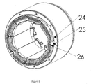
- FIG. 5 An alternate configuration in Figure 5 is shown as a three dimensional view of a concentrated wound stator.
- the stator yoke 24, stator teeth 25, and windings 26 accomplish this concentrated wound configuration.
- Figure 6 shows a cross sectional view that better shows the stator yoke 24 and stator teeth 25.
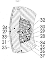
- the cross sectional view of the windings is better shown in Figure 7 where coil bundles 28,19,30, 31 are shown that comprise a single winding.
- This configuration shows cooling bars 32 and 33 located in the middle of the slot between windings as well as cooling bars 34,35,36, 37 located between the tooth 25 and the windings.
- Alternate configurations could have only some of these cooling bars, have fewer or more coil bundles in each winding, or be a distributed wound solution.
- the wire is rectangular in shape with the wide dimension on the wire being in the circumaxial direction of the machine. This is the same direction as the narrow dimension on the coil bundle as shown in Figure 7 .
Landscapes
- Engineering & Computer Science (AREA)
- Power Engineering (AREA)
- Windings For Motors And Generators (AREA)
Applications Claiming Priority (3)
| Application Number | Priority Date | Filing Date | Title |
|---|---|---|---|
| US13/855,801 US10770953B2 (en) | 2013-04-03 | 2013-04-03 | Liquid cooled stator for high efficiency machine |
| EP14778889.7A EP2982023B8 (de) | 2013-04-03 | 2014-03-31 | Flüssigkeitsgekühlter stator für hochleistungsmaschine |
| PCT/US2014/032369 WO2014165440A1 (en) | 2013-04-03 | 2014-03-31 | Liquid cooled stator for high efficiency machine |
Related Parent Applications (2)
| Application Number | Title | Priority Date | Filing Date |
|---|---|---|---|
| EP14778889.7A Division-Into EP2982023B8 (de) | 2013-04-03 | 2014-03-31 | Flüssigkeitsgekühlter stator für hochleistungsmaschine |
| EP14778889.7A Division EP2982023B8 (de) | 2013-04-03 | 2014-03-31 | Flüssigkeitsgekühlter stator für hochleistungsmaschine |
Publications (2)
| Publication Number | Publication Date |
|---|---|
| EP3719963A1 true EP3719963A1 (de) | 2020-10-07 |
| EP3719963B1 EP3719963B1 (de) | 2025-09-10 |
Family
ID=51653955
Family Applications (2)
| Application Number | Title | Priority Date | Filing Date |
|---|---|---|---|
| EP14778889.7A Active EP2982023B8 (de) | 2013-04-03 | 2014-03-31 | Flüssigkeitsgekühlter stator für hochleistungsmaschine |
| EP20174454.7A Active EP3719963B1 (de) | 2013-04-03 | 2014-03-31 | Flüssigkeitsgekühlter stator für hochleistungsmaschine |
Family Applications Before (1)
| Application Number | Title | Priority Date | Filing Date |
|---|---|---|---|
| EP14778889.7A Active EP2982023B8 (de) | 2013-04-03 | 2014-03-31 | Flüssigkeitsgekühlter stator für hochleistungsmaschine |
Country Status (4)
| Country | Link |
|---|---|
| US (2) | US10770953B2 (de) |
| EP (2) | EP2982023B8 (de) |
| CN (2) | CN105308832B (de) |
| WO (1) | WO2014165440A1 (de) |
Families Citing this family (47)
| Publication number | Priority date | Publication date | Assignee | Title |
|---|---|---|---|---|
| DE102016215423A1 (de) * | 2016-08-17 | 2018-02-22 | Bayerische Motoren Werke Aktiengesellschaft | Elektrische Maschine und Fahrzeug mit der elektrischen Maschine |
| CN106655563B (zh) * | 2016-12-01 | 2018-10-26 | 华中科技大学 | 一种电机冷却结构及具有该结构的无机壳电机 |
| DE102017103128A1 (de) | 2017-02-16 | 2018-08-16 | Dr. Ing. H.C. F. Porsche Aktiengesellschaft | Spulensegment für eine Statorspule und Verfahren zur Herstellung eines Spulensegments |
| DE102017208566A1 (de) * | 2017-05-19 | 2018-11-22 | Mahle International Gmbh | Elektrische Maschine, insbesondere für ein Fahrzeug |
| DE102017208546A1 (de) * | 2017-05-19 | 2018-11-22 | Mahle International Gmbh | Elektrische Maschine, insbesondere für ein Fahrzeug |
| DE102017208564A1 (de) * | 2017-05-19 | 2018-11-22 | Mahle International Gmbh | Elektrische Maschine, insbesondere für ein Fahrzeug |
| WO2018218314A1 (en) * | 2017-06-02 | 2018-12-06 | magniX Technologies Pty Ltd | Cooling arrangements in devices or components with windings |
| US10910916B2 (en) | 2017-11-30 | 2021-02-02 | General Electric Company | Fluid cooled and fluid insulated electric machine |
| DE102017221835A1 (de) | 2017-12-04 | 2019-06-06 | Mahle International Gmbh | Elektrische Maschine, insbesondere für ein Fahrzeug |
| EP3499685B1 (de) * | 2017-12-13 | 2021-10-20 | FERRARI S.p.A. | Stator einer elektrischen maschine mit fluidkühlung |
| FI128225B (en) * | 2018-03-20 | 2020-01-15 | Lappeenrannan Teknillinen Yliopisto | Stator for electric machine and electric machine |
| DE102018206512A1 (de) * | 2018-04-26 | 2019-10-31 | Siemens Aktiengesellschaft | Elektrische Maschine und hybridelektrisches Luftfahrzeug |
| DE102018006274A1 (de) | 2018-08-08 | 2019-12-05 | Daimler Ag | Aktivteil für eine elektrische Maschine, insbesondere eines Kraftfahrzeugs |
| DE102018214525A1 (de) * | 2018-08-28 | 2020-03-05 | Mahle International Gmbh | Ringförmiger Stator eines Elektromotors |
| DE102018219219B4 (de) * | 2018-11-12 | 2020-10-22 | Audi Ag | Stator für eine elektrische Maschine |
| DE102018219821A1 (de) * | 2018-11-19 | 2020-06-04 | Mahle International Gmbh | Isolationskörper für eine elektrische Maschine |
| DE102018219822A1 (de) * | 2018-11-19 | 2020-05-20 | Mahle International Gmbh | Isolationskörper für eine elektrische Maschine |
| DE102018219820A1 (de) * | 2018-11-19 | 2020-06-04 | Mahle International Gmbh | Isolationskörper für eine elektrische Maschine |
| US10938266B2 (en) | 2018-12-27 | 2021-03-02 | Abb Schweiz Ag | Electrical machine with cooling channel |
| CA3134252A1 (en) * | 2019-03-19 | 2020-09-24 | Magna International Inc. | High performance electromagnetic machine and cooling system |
| WO2021089189A1 (en) | 2019-11-06 | 2021-05-14 | Eaton Intelligent Power Limited | Axial flux motor with air cooling system |
| EP3820025B1 (de) * | 2019-11-08 | 2025-10-15 | Hamilton Sundstrand Corporation | Abstandshalter für eine statorwicklung |
| US11228216B2 (en) * | 2019-11-15 | 2022-01-18 | Ford Global Technologies, Llc | Stator for electric machine with conductors with varying cross-sectional shapes |
| WO2021115632A1 (en) | 2019-12-10 | 2021-06-17 | Eaton Intelligent Power Limited | Axial flux motor with cooling jacket |
| US11489377B2 (en) * | 2019-12-11 | 2022-11-01 | Lc Advanced Motor Technology Corporation | Rotary electric machine having winding coils with first and second portions connected in series |
| US11095181B2 (en) | 2020-01-17 | 2021-08-17 | Lcdrives Corp. | Rotary electric machine |
| US11539269B2 (en) * | 2020-01-17 | 2022-12-27 | Lc Advanced Motor Technology Corporation | Cooling manifold for rotary electric machine |
| US11418091B2 (en) * | 2020-01-17 | 2022-08-16 | Koch Engineered Solutions, Llc | Cooling device for rotary electric machine |
| JP6804700B1 (ja) * | 2020-01-21 | 2020-12-23 | 三菱電機株式会社 | 固定子およびこれを用いた回転電機 |
| WO2021149131A1 (ja) * | 2020-01-21 | 2021-07-29 | 三菱電機株式会社 | 固定子およびこれを用いた回転電機 |
| US11996734B2 (en) * | 2020-01-21 | 2024-05-28 | Mitsubishi Electric Corporation | Stator and rotary electric machine using same |
| WO2021164946A1 (en) * | 2020-02-21 | 2021-08-26 | Eaton Intelligent Power Limited | Electric motor with integrated cooling system |
| US12424897B2 (en) | 2020-02-21 | 2025-09-23 | Eaton Intelligent Power Limited | Electric motor with integrated cooling system |
| CN111463919B (zh) * | 2020-05-15 | 2021-11-05 | 珠海格力节能环保制冷技术研究中心有限公司 | 电机及具有其的压缩机 |
| CN111463918B (zh) * | 2020-05-15 | 2021-11-05 | 珠海格力节能环保制冷技术研究中心有限公司 | 压缩机及具有其的空调器 |
| CN112398245B (zh) * | 2020-09-28 | 2021-12-17 | 珠海格力节能环保制冷技术研究中心有限公司 | 一种外置式温控装置及永磁同步电机 |
| DE102020212923A1 (de) * | 2020-10-14 | 2022-04-14 | Vitesco Technologies Germany Gmbh | Stator mit integrierter Kühlung, Verfahren zur Herstellung eines Stators und elektrische Maschine |
| AU2021426833A1 (en) * | 2021-02-09 | 2023-09-21 | Hamilton Sundstrand Corporation | Header guiding fluid flow to and from cooling channels in a high density motor |
| JP2024506616A (ja) * | 2021-02-09 | 2024-02-14 | ハミルトン・サンドストランド・コーポレイション | 高密度モータの冷却チャネル |
| GB2609640A (en) * | 2021-08-11 | 2023-02-15 | Saietta Group PLC | Radial flux electrical machine |
| US12212217B2 (en) | 2022-05-13 | 2025-01-28 | Wisconsin Alumni Research Foundation | System and method for electric machine cooling |
| CN115360838B (zh) * | 2022-09-21 | 2023-09-12 | 哈尔滨理工大学 | 大型散式绕组同步电机齿轭分离型逆流式通风冷却系统 |
| US11637463B1 (en) | 2022-10-16 | 2023-04-25 | RH Motor Industry, LLC | Double rotor brushless direct-current motor with fluid cooling |
| US11632022B1 (en) | 2022-11-30 | 2023-04-18 | RH Motor Industry, LLC | Brushed direct-current slip ring motor |
| GB202306936D0 (en) | 2023-05-11 | 2023-06-28 | Rolls Royce Deutschland Ltd & Co Kg | Stator for an electrical machine |
| WO2025078109A1 (en) * | 2023-10-09 | 2025-04-17 | Asml Netherlands B.V. | Cooling and mechanical structure for a distributed wound poly-phase forcer |
| EP4708639A1 (de) * | 2024-09-10 | 2026-03-11 | Garrett International I Inc. | E-maschinensystem mit wicklungsanordnung mit kühlkanälen |
Citations (9)
| Publication number | Priority date | Publication date | Assignee | Title |
|---|---|---|---|---|
| US4446393A (en) | 1976-10-29 | 1984-05-01 | The Globe Tool & Engineering Company | Dynamoelectric field assembly and winding therefor |
| US4712035A (en) | 1985-11-12 | 1987-12-08 | General Electric Company | Salient pole core and salient pole electronically commutated motor |
| US5448118A (en) | 1991-10-05 | 1995-09-05 | Fanuc Limited | Liquid cooled motor and its jacket |
| US5583387A (en) | 1993-06-14 | 1996-12-10 | Matsushita Electric Industrial Co., Ltd. | Stator of dynamo-electric machine |
| US5973427A (en) * | 1997-03-28 | 1999-10-26 | Aisin Seiki Kabushiki Kaisha | Cooling device for electric motor |
| WO2001033698A1 (en) * | 1999-11-03 | 2001-05-10 | Baldor Electric Company | Fluid-cooled, high power switched reluctance motor |
| US20100066198A1 (en) | 2007-03-06 | 2010-03-18 | Shingo Fubuki | Insertion of pre-fabricated concentrated windings into stator slots |
| EP2182570A1 (de) * | 2008-10-28 | 2010-05-05 | Siemens Aktiengesellschaft | Anordnung zur Kühlung einer elektrischen Maschine |
| US8129880B2 (en) | 2007-11-15 | 2012-03-06 | GM Global Technology Operations LLC | Concentrated winding machine with magnetic slot wedges |
Family Cites Families (52)
| Publication number | Priority date | Publication date | Assignee | Title |
|---|---|---|---|---|
| US2695368A (en) * | 1953-01-27 | 1954-11-23 | Gen Electric | Dynamoelectric machine stator winding with fluid-cooling passages in conductor bars |
| US2975088A (en) * | 1956-02-29 | 1961-03-14 | Allis Chalmers Mfg Co | Unsupported silicone rubber electrical insulation and method of preparing same |
| US2897382A (en) * | 1957-02-04 | 1959-07-28 | British Thomson Houston Co Ltd | Dynamo-electric machines |
| US3089048A (en) * | 1960-06-03 | 1963-05-07 | Gen Electric | Winding support system for a dynamoelectric machine |
| GB1128194A (en) * | 1966-05-11 | 1968-09-25 | Ass Elect Ind | Improvements in or relating to dynamo-electric machines |
| GB1117433A (en) * | 1966-06-07 | 1968-06-19 | English Electric Co Ltd | Improvements in alternating current generators |
| US3459679A (en) | 1967-03-07 | 1969-08-05 | Mobil Oil Corp | Catalyst prepared by steaming alkali metal aluminosilicate in a matrix with polyvalent metal salt |
| US3801843A (en) * | 1972-06-16 | 1974-04-02 | Gen Electric | Rotating electrical machine having rotor and stator cooled by means of heat pipes |
| NO145541C (no) | 1976-05-19 | 1982-04-14 | Ciba Geigy Ag | Herdbar blanding omfattende aromatisk amin, metallnitrat og eposyharpiks |
| US4149309A (en) * | 1977-07-27 | 1979-04-17 | Mitsui Mfg. Co., Ltd. | Laminated core manufacture |
| JPS5943896B2 (ja) * | 1977-09-29 | 1984-10-25 | 株式会社東芝 | 電気機器鉄心 |
| US4404486A (en) * | 1980-12-24 | 1983-09-13 | General Electric Company | Star connected air gap polyphase armature having limited voltage gradients at phase boundaries |
| JPS6035929A (ja) * | 1983-08-04 | 1985-02-23 | Moriyama Kogyo Kk | 電磁機における極鉄心と継鉄の結合構造 |
| GB2258765B (en) * | 1991-06-27 | 1996-01-10 | Dana Corp | Variable reluctance motor having foil wire wound coils |
| US5140204A (en) * | 1991-07-05 | 1992-08-18 | Westinghouse Electric Corp. | Heat pipes for cooling pole windings of salient pole machines |
| US5473207A (en) * | 1993-11-04 | 1995-12-05 | General Electric Co. | Cooling pads for water-cooled stator cores in dynamoelectric machines and methods of fabrication |
| EP0917757B1 (de) * | 1996-08-09 | 2004-10-13 | The Turbo Genset Company Limited | Rotierende elektrische maschinen |
| JP3613994B2 (ja) * | 1998-02-12 | 2005-01-26 | トヨタ自動車株式会社 | 平角線コイル製造装置および平角線コイル製造方法 |
| JP3735197B2 (ja) | 1998-02-27 | 2006-01-18 | 株式会社日立製作所 | コイル成形体の製造方法およびそれに用いる金型 |
| SE517323C2 (sv) | 1998-06-30 | 2002-05-28 | Emotron Ab | Kylningsanordning för en elektrisk maskin |
| US6313556B1 (en) | 1999-09-30 | 2001-11-06 | Reliance Electric Technologies, Llc | Superconducting electromechanical rotating device having a liquid-cooled, potted, one layer stator winding |
| US6509665B1 (en) * | 1999-10-25 | 2003-01-21 | Matsushita Electric Industial Co., Ltd. | Motor having stator with insulator of high heat-conductivity |
| TW517430B (en) * | 2000-06-02 | 2003-01-11 | Moric Kabushiki Kaisha | Coil winding for DC machine |
| DE10105076A1 (de) | 2001-02-05 | 2002-08-29 | Siemens Ag | Vorrichtung zur Fixierung eines Wicklungssystems |
| JP2002300753A (ja) | 2001-03-30 | 2002-10-11 | Japan Servo Co Ltd | 内転形回転電機の電機子製造方法及び該製造方法により製造された内転形回転電機の電機子 |
| ES2319392T3 (es) * | 2001-04-20 | 2009-05-07 | Converteam Ltd | Refrigeracion de un arrollamiento de entrehierro de maquinas electricas. |
| US20020163275A1 (en) * | 2001-05-04 | 2002-11-07 | Chun-Pu Hsu | Device with a stator having high performance flat coils |
| GB0111629D0 (en) * | 2001-05-11 | 2001-07-04 | Switched Reluctance Drives Ltd | Cooling of electrical machines |
| GB0118565D0 (en) * | 2001-07-31 | 2001-09-19 | Alstom | Electric machine component cooling |
| US6633097B2 (en) * | 2001-09-10 | 2003-10-14 | General Electric Company | Mechanical joining for water-cooled motor frame |
| US20040100154A1 (en) * | 2002-11-26 | 2004-05-27 | Rahman Khwaja M. | Concentrated winding electric motor having optimized winding cooling and slot fill |
| JP4442207B2 (ja) * | 2003-12-05 | 2010-03-31 | 日産自動車株式会社 | 回転電機の冷却構造 |
| US7183678B2 (en) * | 2004-01-27 | 2007-02-27 | General Electric Company | AC winding with integrated cooling system and method for making the same |
| JP2005348522A (ja) * | 2004-06-03 | 2005-12-15 | Hitachi Ltd | 電動パワーステアリング用モータおよびその製造方法 |
| US20060043801A1 (en) * | 2004-08-27 | 2006-03-02 | Caterpillar Inc. | Liquid cooled switched reluctance electric machine |
| US7254763B2 (en) | 2004-09-01 | 2007-08-07 | Agere Systems Inc. | Built-in self test for memory arrays using error correction coding |
| US7698803B2 (en) * | 2004-09-09 | 2010-04-20 | Mitsui High-Tec, Inc. | Method of manufacturing laminated core |
| US7579724B2 (en) | 2006-06-02 | 2009-08-25 | General Electric Company | Methods and apparatus for using an electrical machine to transport fluids through a pipeline |
| US7569955B2 (en) * | 2006-06-19 | 2009-08-04 | Thermal Motor Innovations, Llc | Electric motor with heat pipes |
| US7705495B2 (en) * | 2006-11-17 | 2010-04-27 | Gm Global Technology Operations, Inc. | Cooling system for an electric motor |
| GB0702997D0 (en) * | 2007-02-16 | 2007-03-28 | Rolls Royce Plc | A cooling arrangement of an electrical machine |
| EP2136455A1 (de) * | 2008-06-19 | 2009-12-23 | Abb Research Ltd. | Mit einer Kühlanordnung ausgestatteter elektrischer Motor |
| EP2182612A1 (de) * | 2008-10-28 | 2010-05-05 | Siemens Aktiengesellschaft | Anordnung zur Kühlung einer elektrischen Maschine |
| JP4670942B2 (ja) * | 2008-11-21 | 2011-04-13 | トヨタ自動車株式会社 | 回転電機 |
| KR101062599B1 (ko) * | 2009-10-21 | 2011-09-06 | 두산중공업 주식회사 | 초전도 회전기기의 냉각 유로 구조 |
| JP5470015B2 (ja) * | 2009-12-04 | 2014-04-16 | 株式会社日立製作所 | 回転電機 |
| EP2378631A1 (de) * | 2010-04-13 | 2011-10-19 | Siemens Aktiengesellschaft | Statoranordnung |
| US20110309695A1 (en) * | 2010-06-21 | 2011-12-22 | Huard Steven R | Internally cooled servo motor with dry rotor |
| JP2013013228A (ja) * | 2011-06-29 | 2013-01-17 | Toyota Motor Corp | 回転電機用ステータ |
| JP6035929B2 (ja) | 2012-07-12 | 2016-11-30 | 株式会社Ihi | 基板折割装置及び基板折割方法 |
| KR101942968B1 (ko) | 2012-11-20 | 2019-04-17 | 삼성전자주식회사 | 향상된 개구율을 갖는 전기습윤 디스플레이 장치 및 그 구동 방법 |
| TWI488409B (zh) * | 2012-11-21 | 2015-06-11 | Ind Tech Res Inst | 定子模組及其磁力產生構件 |
-
2013
- 2013-04-03 US US13/855,801 patent/US10770953B2/en active Active
-
2014
- 2014-03-31 CN CN201480019567.1A patent/CN105308832B/zh not_active Expired - Fee Related
- 2014-03-31 CN CN202011433532.6A patent/CN112910182A/zh active Pending
- 2014-03-31 WO PCT/US2014/032369 patent/WO2014165440A1/en not_active Ceased
- 2014-03-31 EP EP14778889.7A patent/EP2982023B8/de active Active
- 2014-03-31 EP EP20174454.7A patent/EP3719963B1/de active Active
-
2020
- 2020-05-01 US US16/864,529 patent/US11245309B2/en active Active
Patent Citations (9)
| Publication number | Priority date | Publication date | Assignee | Title |
|---|---|---|---|---|
| US4446393A (en) | 1976-10-29 | 1984-05-01 | The Globe Tool & Engineering Company | Dynamoelectric field assembly and winding therefor |
| US4712035A (en) | 1985-11-12 | 1987-12-08 | General Electric Company | Salient pole core and salient pole electronically commutated motor |
| US5448118A (en) | 1991-10-05 | 1995-09-05 | Fanuc Limited | Liquid cooled motor and its jacket |
| US5583387A (en) | 1993-06-14 | 1996-12-10 | Matsushita Electric Industrial Co., Ltd. | Stator of dynamo-electric machine |
| US5973427A (en) * | 1997-03-28 | 1999-10-26 | Aisin Seiki Kabushiki Kaisha | Cooling device for electric motor |
| WO2001033698A1 (en) * | 1999-11-03 | 2001-05-10 | Baldor Electric Company | Fluid-cooled, high power switched reluctance motor |
| US20100066198A1 (en) | 2007-03-06 | 2010-03-18 | Shingo Fubuki | Insertion of pre-fabricated concentrated windings into stator slots |
| US8129880B2 (en) | 2007-11-15 | 2012-03-06 | GM Global Technology Operations LLC | Concentrated winding machine with magnetic slot wedges |
| EP2182570A1 (de) * | 2008-10-28 | 2010-05-05 | Siemens Aktiengesellschaft | Anordnung zur Kühlung einer elektrischen Maschine |
Also Published As
| Publication number | Publication date |
|---|---|
| WO2014165440A1 (en) | 2014-10-09 |
| EP2982023B1 (de) | 2020-09-02 |
| CN105308832A (zh) | 2016-02-03 |
| CN112910182A (zh) | 2021-06-04 |
| CN105308832B (zh) | 2021-03-12 |
| US20140300220A1 (en) | 2014-10-09 |
| EP2982023B8 (de) | 2020-10-28 |
| EP3719963B1 (de) | 2025-09-10 |
| EP2982023A1 (de) | 2016-02-10 |
| US11245309B2 (en) | 2022-02-08 |
| US20200259399A1 (en) | 2020-08-13 |
| US10770953B2 (en) | 2020-09-08 |
| EP2982023A4 (de) | 2017-03-01 |
Similar Documents
| Publication | Publication Date | Title |
|---|---|---|
| US11245309B2 (en) | Liquid cooled stator for high efficiency machine | |
| EP0225132B1 (de) | Stator für eine elektrische Maschine | |
| US7851966B2 (en) | Stator for electric machine with improved efficiency and thermal performance | |
| US9712011B2 (en) | Electric machine with modular stator coils and cooling tubes | |
| US4852245A (en) | Toothless stator electrical machine construction method | |
| US9379585B2 (en) | Winding construction for high efficiency machine | |
| US10348146B2 (en) | Liquid cooled high efficiency permanent magnet machine with glycol cooling | |
| US9362785B2 (en) | Concentrated winding stator construction for high efficiency machine | |
| US11255612B2 (en) | Wound strip machine | |
| CN103404003A (zh) | 旋转电机用定子 | |
| CN112673548A (zh) | 轴向磁通电机和辅助组件 | |
| EP3093961A2 (de) | Wicklungen für elektrische maschinen | |
| US10756583B2 (en) | Wound strip machine | |
| CN109075624A (zh) | 用于在电机中容纳多种导体几何形状的公共层叠部件 | |
| WO2016189192A1 (en) | A winding of an electric machine | |
| US20220200367A1 (en) | Stator for electrical machines | |
| CA2390340C (en) | Electrical machine comprising a stator with windings | |
| US11757335B2 (en) | Cooling channels in a high-density motor | |
| EP2873138B1 (de) | Glycolgekühlte hocheffiziente permanentmagnetmaschine | |
| EP1727263A2 (de) | Wassergekühlte Statorwicklung eines Elektromotors | |
| US3719844A (en) | Dynamo-electric machines | |
| EP2918001A2 (de) | Kompakte permanentmagnetmaschinenkonstruktion | |
| WO2020199732A1 (zh) | 定子分段组件及发电机 | |
| US20140354106A1 (en) | Reduction of leakage flux in electrical machines |
Legal Events
| Date | Code | Title | Description |
|---|---|---|---|
| PUAI | Public reference made under article 153(3) epc to a published international application that has entered the european phase |
Free format text: ORIGINAL CODE: 0009012 |
|
| STAA | Information on the status of an ep patent application or granted ep patent |
Free format text: STATUS: THE APPLICATION HAS BEEN PUBLISHED |
|
| AC | Divisional application: reference to earlier application |
Ref document number: 2982023 Country of ref document: EP Kind code of ref document: P |
|
| AK | Designated contracting states |
Kind code of ref document: A1 Designated state(s): AL AT BE BG CH CY CZ DE DK EE ES FI FR GB GR HR HU IE IS IT LI LT LU LV MC MK MT NL NO PL PT RO RS SE SI SK SM TR |
|
| STAA | Information on the status of an ep patent application or granted ep patent |
Free format text: STATUS: REQUEST FOR EXAMINATION WAS MADE |
|
| 17P | Request for examination filed |
Effective date: 20210215 |
|
| RBV | Designated contracting states (corrected) |
Designated state(s): AL AT BE BG CH CY CZ DE DK EE ES FI FR GB GR HR HU IE IS IT LI LT LU LV MC MK MT NL NO PL PT RO RS SE SI SK SM TR |
|
| STAA | Information on the status of an ep patent application or granted ep patent |
Free format text: STATUS: EXAMINATION IS IN PROGRESS |
|
| 17Q | First examination report despatched |
Effective date: 20230405 |
|
| GRAP | Despatch of communication of intention to grant a patent |
Free format text: ORIGINAL CODE: EPIDOSNIGR1 |
|
| STAA | Information on the status of an ep patent application or granted ep patent |
Free format text: STATUS: GRANT OF PATENT IS INTENDED |
|
| INTG | Intention to grant announced |
Effective date: 20241122 |
|
| RIN1 | Information on inventor provided before grant (corrected) |
Inventor name: MARVIN, RUSSEL HUGH |
|
| GRAJ | Information related to disapproval of communication of intention to grant by the applicant or resumption of examination proceedings by the epo deleted |
Free format text: ORIGINAL CODE: EPIDOSDIGR1 |
|
| GRAJ | Information related to disapproval of communication of intention to grant by the applicant or resumption of examination proceedings by the epo deleted |
Free format text: ORIGINAL CODE: EPIDOSDIGR1 |
|
| STAA | Information on the status of an ep patent application or granted ep patent |
Free format text: STATUS: EXAMINATION IS IN PROGRESS |
|
| GRAP | Despatch of communication of intention to grant a patent |
Free format text: ORIGINAL CODE: EPIDOSNIGR1 |
|
| STAA | Information on the status of an ep patent application or granted ep patent |
Free format text: STATUS: GRANT OF PATENT IS INTENDED |
|
| INTG | Intention to grant announced |
Effective date: 20241122 |
|
| RAP1 | Party data changed (applicant data changed or rights of an application transferred) |
Owner name: LC ADVANCED MOTOR TECHNOLOGY CORPORATION |
|
| INTG | Intention to grant announced |
Effective date: 20250331 |
|
| GRAS | Grant fee paid |
Free format text: ORIGINAL CODE: EPIDOSNIGR3 |
|
| GRAA | (expected) grant |
Free format text: ORIGINAL CODE: 0009210 |
|
| STAA | Information on the status of an ep patent application or granted ep patent |
Free format text: STATUS: THE PATENT HAS BEEN GRANTED |
|
| AC | Divisional application: reference to earlier application |
Ref document number: 2982023 Country of ref document: EP Kind code of ref document: P |
|
| AK | Designated contracting states |
Kind code of ref document: B1 Designated state(s): AL AT BE BG CH CY CZ DE DK EE ES FI FR GB GR HR HU IE IS IT LI LT LU LV MC MK MT NL NO PL PT RO RS SE SI SK SM TR |
|
| REG | Reference to a national code |
Ref country code: GB Ref legal event code: FG4D |
|
| REG | Reference to a national code |
Ref country code: CH Ref legal event code: EP |
|
| REG | Reference to a national code |
Ref country code: DE Ref legal event code: R096 Ref document number: 602014092382 Country of ref document: DE |
|
| REG | Reference to a national code |
Ref country code: IE Ref legal event code: FG4D |
|
| REG | Reference to a national code |
Ref country code: NL Ref legal event code: FP |
|
| PG25 | Lapsed in a contracting state [announced via postgrant information from national office to epo] |
Ref country code: NO Free format text: LAPSE BECAUSE OF FAILURE TO SUBMIT A TRANSLATION OF THE DESCRIPTION OR TO PAY THE FEE WITHIN THE PRESCRIBED TIME-LIMIT Effective date: 20251210 |
|
| REG | Reference to a national code |
Ref country code: LT Ref legal event code: MG9D |
|
| PG25 | Lapsed in a contracting state [announced via postgrant information from national office to epo] |
Ref country code: FI Free format text: LAPSE BECAUSE OF FAILURE TO SUBMIT A TRANSLATION OF THE DESCRIPTION OR TO PAY THE FEE WITHIN THE PRESCRIBED TIME-LIMIT Effective date: 20250910 |
|
| PG25 | Lapsed in a contracting state [announced via postgrant information from national office to epo] |
Ref country code: HR Free format text: LAPSE BECAUSE OF FAILURE TO SUBMIT A TRANSLATION OF THE DESCRIPTION OR TO PAY THE FEE WITHIN THE PRESCRIBED TIME-LIMIT Effective date: 20250910 |
|
| PG25 | Lapsed in a contracting state [announced via postgrant information from national office to epo] |
Ref country code: GR Free format text: LAPSE BECAUSE OF FAILURE TO SUBMIT A TRANSLATION OF THE DESCRIPTION OR TO PAY THE FEE WITHIN THE PRESCRIBED TIME-LIMIT Effective date: 20251211 |
|
| PG25 | Lapsed in a contracting state [announced via postgrant information from national office to epo] |
Ref country code: SE Free format text: LAPSE BECAUSE OF FAILURE TO SUBMIT A TRANSLATION OF THE DESCRIPTION OR TO PAY THE FEE WITHIN THE PRESCRIBED TIME-LIMIT Effective date: 20250910 |
|
| PG25 | Lapsed in a contracting state [announced via postgrant information from national office to epo] |
Ref country code: LV Free format text: LAPSE BECAUSE OF FAILURE TO SUBMIT A TRANSLATION OF THE DESCRIPTION OR TO PAY THE FEE WITHIN THE PRESCRIBED TIME-LIMIT Effective date: 20250910 |
|
| PG25 | Lapsed in a contracting state [announced via postgrant information from national office to epo] |
Ref country code: PL Free format text: LAPSE BECAUSE OF FAILURE TO SUBMIT A TRANSLATION OF THE DESCRIPTION OR TO PAY THE FEE WITHIN THE PRESCRIBED TIME-LIMIT Effective date: 20250910 Ref country code: BG Free format text: LAPSE BECAUSE OF FAILURE TO SUBMIT A TRANSLATION OF THE DESCRIPTION OR TO PAY THE FEE WITHIN THE PRESCRIBED TIME-LIMIT Effective date: 20250910 |
|
| PG25 | Lapsed in a contracting state [announced via postgrant information from national office to epo] |
Ref country code: RS Free format text: LAPSE BECAUSE OF FAILURE TO SUBMIT A TRANSLATION OF THE DESCRIPTION OR TO PAY THE FEE WITHIN THE PRESCRIBED TIME-LIMIT Effective date: 20251210 |
|
| PG25 | Lapsed in a contracting state [announced via postgrant information from national office to epo] |
Ref country code: ES Free format text: LAPSE BECAUSE OF FAILURE TO SUBMIT A TRANSLATION OF THE DESCRIPTION OR TO PAY THE FEE WITHIN THE PRESCRIBED TIME-LIMIT Effective date: 20250910 |
|
| REG | Reference to a national code |
Ref country code: AT Ref legal event code: MK05 Ref document number: 1836959 Country of ref document: AT Kind code of ref document: T Effective date: 20250910 |
|
| PG25 | Lapsed in a contracting state [announced via postgrant information from national office to epo] |
Ref country code: SM Free format text: LAPSE BECAUSE OF FAILURE TO SUBMIT A TRANSLATION OF THE DESCRIPTION OR TO PAY THE FEE WITHIN THE PRESCRIBED TIME-LIMIT Effective date: 20250910 |
|
| PG25 | Lapsed in a contracting state [announced via postgrant information from national office to epo] |
Ref country code: AT Free format text: LAPSE BECAUSE OF FAILURE TO SUBMIT A TRANSLATION OF THE DESCRIPTION OR TO PAY THE FEE WITHIN THE PRESCRIBED TIME-LIMIT Effective date: 20250910 |
|
| PG25 | Lapsed in a contracting state [announced via postgrant information from national office to epo] |
Ref country code: IS Free format text: LAPSE BECAUSE OF FAILURE TO SUBMIT A TRANSLATION OF THE DESCRIPTION OR TO PAY THE FEE WITHIN THE PRESCRIBED TIME-LIMIT Effective date: 20260110 |
|
| PG25 | Lapsed in a contracting state [announced via postgrant information from national office to epo] |
Ref country code: PT Free format text: LAPSE BECAUSE OF FAILURE TO SUBMIT A TRANSLATION OF THE DESCRIPTION OR TO PAY THE FEE WITHIN THE PRESCRIBED TIME-LIMIT Effective date: 20260112 Ref country code: CZ Free format text: LAPSE BECAUSE OF FAILURE TO SUBMIT A TRANSLATION OF THE DESCRIPTION OR TO PAY THE FEE WITHIN THE PRESCRIBED TIME-LIMIT Effective date: 20250910 |
|
| PG25 | Lapsed in a contracting state [announced via postgrant information from national office to epo] |
Ref country code: SK Free format text: LAPSE BECAUSE OF FAILURE TO SUBMIT A TRANSLATION OF THE DESCRIPTION OR TO PAY THE FEE WITHIN THE PRESCRIBED TIME-LIMIT Effective date: 20250910 Ref country code: EE Free format text: LAPSE BECAUSE OF FAILURE TO SUBMIT A TRANSLATION OF THE DESCRIPTION OR TO PAY THE FEE WITHIN THE PRESCRIBED TIME-LIMIT Effective date: 20250910 |