EP3720161A1 - Procédé et appareil de transmission de canal - Google Patents
Procédé et appareil de transmission de canal Download PDFInfo
- Publication number
- EP3720161A1 EP3720161A1 EP18905333.3A EP18905333A EP3720161A1 EP 3720161 A1 EP3720161 A1 EP 3720161A1 EP 18905333 A EP18905333 A EP 18905333A EP 3720161 A1 EP3720161 A1 EP 3720161A1
- Authority
- EP
- European Patent Office
- Prior art keywords
- rnti
- data
- terminal device
- base station
- check
- Prior art date
- Legal status (The legal status is an assumption and is not a legal conclusion. Google has not performed a legal analysis and makes no representation as to the accuracy of the status listed.)
- Granted
Links
Images


Classifications
-
- H—ELECTRICITY
- H04—ELECTRIC COMMUNICATION TECHNIQUE
- H04W—WIRELESS COMMUNICATION NETWORKS
- H04W8/00—Network data management
- H04W8/26—Network addressing or numbering for mobility support
-
- H—ELECTRICITY
- H04—ELECTRIC COMMUNICATION TECHNIQUE
- H04W—WIRELESS COMMUNICATION NETWORKS
- H04W72/00—Local resource management
- H04W72/20—Control channels or signalling for resource management
- H04W72/23—Control channels or signalling for resource management in the downlink direction of a wireless link, i.e. towards a terminal
-
- H—ELECTRICITY
- H04—ELECTRIC COMMUNICATION TECHNIQUE
- H04L—TRANSMISSION OF DIGITAL INFORMATION, e.g. TELEGRAPHIC COMMUNICATION
- H04L1/00—Arrangements for detecting or preventing errors in the information received
- H04L1/004—Arrangements for detecting or preventing errors in the information received by using forward error control
- H04L1/0056—Systems characterized by the type of code used
- H04L1/0061—Error detection codes
-
- H—ELECTRICITY
- H04—ELECTRIC COMMUNICATION TECHNIQUE
- H04L—TRANSMISSION OF DIGITAL INFORMATION, e.g. TELEGRAPHIC COMMUNICATION
- H04L1/00—Arrangements for detecting or preventing errors in the information received
- H04L1/004—Arrangements for detecting or preventing errors in the information received by using forward error control
- H04L1/0056—Systems characterized by the type of code used
- H04L1/0067—Rate matching
-
- H—ELECTRICITY
- H04—ELECTRIC COMMUNICATION TECHNIQUE
- H04L—TRANSMISSION OF DIGITAL INFORMATION, e.g. TELEGRAPHIC COMMUNICATION
- H04L5/00—Arrangements affording multiple use of the transmission path
- H04L5/003—Arrangements for allocating sub-channels of the transmission path
- H04L5/0044—Allocation of payload; Allocation of data channels, e.g. PDSCH or PUSCH
-
- H—ELECTRICITY
- H04—ELECTRIC COMMUNICATION TECHNIQUE
- H04L—TRANSMISSION OF DIGITAL INFORMATION, e.g. TELEGRAPHIC COMMUNICATION
- H04L5/00—Arrangements affording multiple use of the transmission path
- H04L5/0091—Signalling for the administration of the divided path, e.g. signalling of configuration information
-
- H—ELECTRICITY
- H04—ELECTRIC COMMUNICATION TECHNIQUE
- H04W—WIRELESS COMMUNICATION NETWORKS
- H04W72/00—Local resource management
- H04W72/04—Wireless resource allocation
- H04W72/044—Wireless resource allocation based on the type of the allocated resource
- H04W72/0453—Resources in frequency domain, e.g. a carrier in FDMA
Definitions
- This application relates to the field of communications technologies, and in particular, to a channel transmission method and an apparatus.
- An Internet of Things (internet of things, IoT) system performs channel transmission by loading to-be-transmitted data onto a subcarrier. There are two channel transmission manners: a scheduling manner and a non-scheduling manner.
- a terminal device and a base station pre-agree on agreement information such as a physical uplink shared channel (physical uplink shared channel, PUSCH) carrier (carrier) index (index) and a modulation and coding scheme (Modulation and Coding Scheme, MCS) index, or the base station allocates, to the terminal device in a process in which the terminal device accesses the base station, the agreement information such as the PUSCH carrier index and the MCS index, and notifies the terminal device.
- agreement information such as a physical uplink shared channel (physical uplink shared channel, PUSCH) carrier (carrier) index (index) and a modulation and coding scheme (Modulation and Coding Scheme, MCS) index
- the terminal device sends, when data needs to be sent, uplink data to the base station on a PUSCH corresponding to the PUSCH carrier index based on the agreement information.
- the base station receives the uplink data on the PUSCH corresponding to the PUSCH carrier index based on the agreement information.
- the terminal device In an uplink channel transmission process, the terminal device usually scrambles the uplink data by using a cell radio network temporary identifier (cell radio network temporary identifier, C-RNTI) of the terminal device.
- a cell radio network temporary identifier cell radio network temporary identifier, C-RNTI
- the base station when receiving the uplink data on the PUSCH, the base station does not know which terminal device sends the uplink data and cannot learn of a scrambling parameter of the uplink data. Therefore, when descrambling the uplink data, the base station performs blind detection by using C-RNTIs of all the terminal devices configured on the PUSCH. Consequently, complexity is relatively high when the base station descrambles the uplink data.
- Embodiments of this application provide a channel transmission method and an apparatus, to resolve a problem of relatively high complexity of uplink data descrambling performed by a base station in the prior art.
- this application provides a channel transmission method, and the method includes: scrambling, by a terminal device in a non-scheduling transmission mode, to-be-sent data by using a first radio network temporary identifier RNTI, where the first RNTI is a preset value, or a correspondence exists between the first RNTI and a specified frequency domain resource index; or scrambling, by the terminal device in a scheduling transmission mode, the to-be-sent data by using a second RNTI, where the second RNTI is different from the first RNTI.
- RNTI radio network temporary identifier
- the terminal device when using the non-scheduling transmission mode, may scramble the to-be-sent data by using the preset value, and the base station may perform descrambling by using the preset value without performing the descrambling in a blind detection manner. Therefore, complexity of the descrambling may be effectively reduced.
- the terminal device when using the non-scheduling transmission mode, may further determine the first RNTI based on the specified frequency domain resource index, and then perform scrambling by using the first RNTI.
- the base station may determine the first RNTI based on the specified frequency domain resource index, and then perform descrambling by using the first RNTI without performing the descrambling in a blind detection manner. Therefore, complexity of the descrambling may be effectively reduced.
- the terminal device may determine the first RNTI based on the specified frequency domain resource index.
- the first RNTI is determined based on the specified frequency domain resource index.
- the scrambling is performed by using the RNTI determined based on the frequency domain resource index, so that the base station may determine, based on a frequency domain resource that receives data, a scrambling parameter of the data. Therefore, the complexity of the descrambling may be effectively reduced.
- the terminal device may perform a modulo operation on the specified frequency domain resource index and the preset value, to obtain the first RNTI.
- the base station may determine the scrambling parameter of the received data based on the preset value and a frequency domain resource index of the frequency domain resource that receives the data, so that the received data may be descrambled based on the determined scrambling parameter. In this way, the blind detection manner may be avoided, and the complexity of the descrambling may be effectively reduced.
- the terminal device may perform cyclic redundancy check CRC coding on the to-be-sent data, to obtain check coded data, perform redundancy information expansion processing on the check coded data, to obtain error-correction coded data, perform rate matching on the error-correction coded data, to obtain rate-matched data, determine a pseudo-random sequence based on the first RNTI, and scramble the rate-matched data by using the pseudo-random sequence.
- the pseudo-random sequence is determined based on the C-RNTI of the terminal device, in the foregoing design, the pseudo-random sequence is determined based on the first RNTI, so that the base station may not care about the C-RNTI of the terminal device that sends data. Therefore, data does not need to be descrambled in the blind detection manner, and the complexity of the descrambling may be effectively reduced.
- the terminal device may perform cyclic redundancy check CRC coding on the to-be-sent data, to obtain check coded data, and then scramble a check bit of the check coded data by using the first RNTI.
- an objective of interference randomization may be achieved by scrambling a CRC by using the first RNTI, so that inter-channel interference may be reduced.
- the terminal device may perform cyclic redundancy check CRC coding on the to-be-sent data, to obtain check coded data, scramble a check bit of the check coded data by using the first RNTI, to obtain scrambled check coded data, perform redundancy information expansion processing on the scrambled check coded data, to obtain error-correction coded data, perform rate matching on the error-correction coded data, to obtain rate-matched data, determine a pseudo-random sequence based on the first RNTI, and scramble the rate-matched data by using the pseudo-random sequence.
- the to-be-sent data is scrambled by using the first RNTI unrelated to an identity of the terminal device, so that the base station may determine a scrambling parameter without using the blind detection manner, and the complexity of the descrambling may be effectively reduced.
- the CRC is scrambled by using the first RNTI, and the pseudo-random sequence is determined based on the first RNTI, so that the objective of the interference randomization may be achieved, thereby reducing the inter-channel interference.
- the terminal device when scrambling the check bit of the check coded data by using the first RNTI, the terminal device performs an exclusive OR operation on the first RNTI and the check bit of the check coded data.
- the interference randomization may be implemented by performing an exclusive OR operation on the first RNTI and the CRC, so that the inter-channel interference may be reduced.
- this application provides a channel transmission method, and the method includes: receiving, by a base station, data sent by a terminal device; and in a non-scheduling transmission mode, descrambling, by the base station, the data by using a first RNTI, where the first RNTI is a preset value, or a correspondence exists between the first RNTI and a specified frequency domain resource index; or in a scheduling transmission mode, descrambling, by the base station, the data by using a second RNTI, where the second RNTI is different from the first RNTI.
- the base station when the terminal device uses the non-scheduling transmission mode, after receiving the data, the base station may not care about the terminal device that sends the data, but may descramble the received data by using the preset value, or descramble the received data based on an RNTI corresponding to the specified frequency domain resource index. Compared with that the base station descrambles the data in a blind detection manner, the foregoing design may effectively reduce complexity of descrambling.
- the base station may determine the first RNTI based on the specified frequency domain resource index.
- a scrambling parameter is a C-RNTI corresponding to the terminal device
- the base station may determine, based on a frequency domain resource that receives data, a scrambling parameter of the data, so that the complexity of the descrambling may be effectively reduced.
- the base station when determining the first RNTI based on the specified frequency domain resource index, may perform a modulo operation on the specified frequency domain resource index and the preset value, to obtain the first RNTI.
- the base station may determine the scrambling parameter of the received data based on the preset value and a frequency domain resource index of the frequency domain resource that receives the data, so that the received data may be descrambled based on the determined scrambling parameter. In this way, the blind detection manner may be avoided, and the complexity of the descrambling may be effectively reduced.
- the base station may determine a pseudo-random sequence based on the first RNTI, and then descramble the data by using the pseudo-random sequence.
- the pseudo-random sequence is determined based on the first RNTI, so that the base station may not care about the C-RNTI of the terminal device that sends data. Therefore, data does not need to be descrambled in the blind detection manner, and the complexity of the descrambling may be effectively reduced.
- the base station may descramble the data, to obtain descrambled data, perform inverse processing of rate matching on the descrambled data, to obtain data that exists before the rate matching, perform de-redundancy processing on the data that exists before the rate matching, to obtain de-redundant data, descramble a check bit of the de-redundant data by using the first RNTI, to obtain check coded data, and perform inverse processing of cyclic redundancy check CRC coding on the check coded data.
- an objective of interference randomization may be achieved by the terminal device by scrambling a CRC by using the first RNTI, so that inter-channel interference may be reduced.
- the base station may determine a pseudo-random sequence based on the first RNTI, descramble the data by using the pseudo-random sequence, to obtain descrambled data, perform inverse processing of rate matching on the descrambled data, to obtain data that exists before the rate matching, perform de-redundancy processing on the data that exists before the rate matching, to obtain de-redundant data, descramble a check bit of the de-redundant data by using the first RNTI, to obtain check coded data, and perform inverse processing of cyclic redundancy check CRC coding on the de-redundant data by using the check coded data.
- the to-be-sent data is scrambled by using the first RNTI unrelated to an identity of the terminal device, so that the base station may determine a scrambling parameter without using the blind detection manner, and the complexity of the descrambling may be effectively reduced.
- the CRC is scrambled by using the first RNTI, and the pseudo-random sequence is determined based on the first RNTI, so that the objective of the interference randomization may be achieved, thereby reducing the inter-channel interference.
- the base station when descrambling the check bit of the de-redundant data by using the first RNTI, the base station may perform an exclusive OR operation on the first RNTI and the check bit of the de-redundant data.
- the interference randomization may be implemented by performing an exclusive OR operation on the first RNTI and the CRC, so that the inter-channel interference may be reduced.
- this application provides a terminal device, including: a scrambling module, configured to: in a non-scheduling transmission mode, scramble to-be-sent data by using a first RNTI, where the first RNTI is a preset value, or a correspondence exists between the first RNTI and a specified frequency domain resource index; or in a non-scheduling transmission mode, scramble the to-be-sent data by using a second RNTI, where the second RNTI is different from the first RNTI.
- a scrambling module configured to: in a non-scheduling transmission mode, scramble to-be-sent data by using a first RNTI, where the first RNTI is a preset value, or a correspondence exists between the first RNTI and a specified frequency domain resource index; or in a non-scheduling transmission mode, scramble the to-be-sent data by using a second RNTI, where the second RNTI is different from the first RNTI.
- the terminal device further includes a determining module, configured to: when the correspondence exists between the first RNTI and the specified frequency domain resource index, determine the first RNTI based on the specified frequency domain resource index.
- the determining module is specifically configured to perform an exclusive OR modulo operation on the specified frequency domain resource index and the preset value, to obtain the first RNTI.
- the scrambling module when scrambling the to-be-sent data by using the first RNTI, is specifically configured to: perform cyclic redundancy check CRC coding on the to-be-sent data, to obtain check coded data; perform redundancy information expansion processing on the check coded data, to obtain error-correction coded data; perform rate matching on the error-correction coded data, to obtain rate-matched data; determine a pseudo-random sequence based on the first RNTI; and scramble the rate-matched data by using the pseudo-random sequence.
- the scrambling module when scrambling the to-be-sent data by using the first RNTI, is specifically configured to: perform cyclic redundancy check CRC coding on the to-be-sent data, to obtain check coded data, and then scramble a check bit of the check coded data by using the first RNTI.
- the scrambling module when scrambling the to-be-sent data by using the first RNTI, is specifically configured to: perform cyclic redundancy check CRC coding on the to-be-sent data, to obtain check coded data; scramble a check bit of the check coded data by using the first RNTI, to obtain scrambled check coded data; perform redundancy information expansion processing on the scrambled check coded data, to obtain error-correction coded data; perform rate matching on the error-correction coded data, to obtain rate-matched data; determine a pseudo-random sequence based on the first RNTI; and scramble the rate-matched data by using the pseudo-random sequence.
- the scrambling module when scrambling the check bit of the check coded data by using the first RNTI, performs an exclusive OR operation on the first RNTI and the check bit of the check coded data.
- this application provides a base station, including: a receiving module, configured to receive data sent by a terminal device; and a descrambling module, configured to: in a non-scheduling transmission mode, descramble the data by using a first RNTI, where the first RNTI is a preset value, or a correspondence exists between the first RNTI and a specified frequency domain resource index; or in a scheduling transmission mode, descramble the data by using a second RNTI, where the second RNTI is different from the first RNTI.
- the base station further includes a determining module, configured to: when the correspondence exists between the first RNTI and the specified frequency domain resource index, determine the first RNTI based on the specified frequency domain resource index.
- the determining module is specifically configured to perform a modulo operation on the specified frequency domain resource index and the preset value, to obtain the first RNTI.
- the descrambling module when descrambling the data by using the first RNTI, is specifically configured to: determine a pseudo-random sequence based on the first RNTI, and descramble the data by using the pseudo-random sequence.
- the descrambling module when descrambling the data by using the first RNTI, is specifically configured to: descramble the data, to obtain descrambled data; perform inverse processing of rate matching on the descrambled data, to obtain data that exists before the rate matching; perform de-redundancy processing on the data that exists before the rate matching, to obtain de-redundant data; descramble a check bit of the de-redundant data by using the first RNTI, to obtain check coded data; and perform inverse processing of cyclic redundancy check CRC coding on the check coded data.
- the descrambling module when descrambling the data by using the first RNTI, is specifically configured to: determine a pseudo-random sequence based on the first RNTI; descramble the data by using the pseudo-random sequence, to obtain the descrambled data; perform inverse processing of rate matching on the descrambled data, to obtain data that exists before the rate matching; perform de-redundancy processing on the data that exists before the rate matching, to obtain de-redundant data; descramble a check bit of the de-redundant data by using the first RNTI, to obtain check coded data; and perform inverse processing of cyclic redundancy check CRC coding on the check coded data.
- the descrambling module when descrambling the check bit of the de-redundant data by using the first RNTI, is specifically configured to perform an exclusive OR operation on the first RNTI and the check bit of the de-redundant data.
- an embodiment of this application further provides a terminal device.
- the terminal device includes a processor and a memory, where the memory is configured to store a software program, and the processor is configured to read the software program stored in the memory and implement the method provided in the first aspect or any design of the first aspect.
- an embodiment of this application further provides a base station.
- the base station includes a processor and a memory, where the memory is configured to store a software program, and the processor is configured to read the software program stored in the memory and implement the method provided in the second aspect or any design of the second aspect.
- an embodiment of this application further provides a computer storage medium.
- the storage medium stores a software program; when read and executed by one or more processors, the software program may implement the method provided in the first aspect or any design of the first aspect, or the method provided in the second aspect or any design of the second aspect.
- an embodiment of this application provides a computer program product including an instruction.
- the computer program product runs on a computer, the computer is enabled to perform the method provided in the first aspect or any design of the first aspect, or the method provided in the second aspect or any design of the second aspect.
- the network architecture and the service scenario described in the embodiments of this application are intended to describe the technical solutions in the embodiments of this application more clearly, and do not constitute a limitation on the technical solutions provided in the embodiments of this application. Persons of ordinary skill in the art may know that: With the evolution of the network architecture and the emergence of new service scenarios, the technical solutions provided in the embodiments of this application are also applicable to similar technical problems.
- a channel transmission method provided in this application may be applied to an Internet of Things (internet of things, IoT) system, and a bandwidth of a channel in the IoT system may be 25 kHz.
- IoT Internet of things
- an architecture of the IoT system includes a terminal device, a base station, and a core network (evolved packet core, EPC). Uplink channel transmission and downlink channel transmission are performed between the base station and the terminal device.
- EPC evolved packet core
- the base station in the IoT system may be a common base station (for example, a Node B or an eNB), a new radio controller (new radio controller, NR controller), a gNodeB (gNB) in a 5G system, a centralized network element (centralized unit), a new radio base station, a radio remote module, a micro base station, a relay (relay), a distributed network element (distributed unit), a transmission reception point (transmission reception point, TRP), a transmission point (transmission point, TP), or any other radio access device.
- a common base station for example, a Node B or an eNB
- a new radio controller new radio controller, NR controller
- gNodeB gNodeB
- 5G system for example, a Node B or an eNB
- a new radio controller new radio controller, NR controller
- gNodeB gNodeB
- 5G system for example, a Node B or an eNB
- the terminal device is also referred to as user equipment (User Equipment, UE), and is a device, for example, a handheld device or a vehicle-mounted device having a wireless connection function, providing voice and/or data connectivity for the terminal device.
- a common terminal includes, for example, a mobile phone, a tablet, a notebook computer, a palmtop computer, a mobile Internet device (mobile internet device, MID), and a wearable device such as a smartwatch, a smart band, or a pedometer.
- channel transmission may be performed between the base station and the terminal device in a non-scheduling-based manner, or data transmission may be performed in a scheduling grant-based manner.
- the terminal device and the base station pre-agree on agreement information such as a physical uplink shared channel (physical uplink shared channel, PUSCH) carrier (carrier) index (index), a modulation and coding scheme (modulation and coding scheme, MCS) index, a period (period), a starting position (offset), and duration (duration), or the base station allocates, to the terminal device in a process in which the terminal device accesses the base station, agreement information such as a PUSCH carrier index, an MCS index, a period, an offset, and duration, and notifies the terminal device.
- agreement information such as a PUSCH carrier index, an MCS index, a period, an offset, and duration, and notifies the terminal device.
- the terminal device sends, when data needs to be sent, uplink data to the base station on a PUSCH corresponding to the PUSCH carrier index based on the agreement information.
- the base station receives the uplink data on the PUSCH corresponding to the PUSCH carrier index based on a modulation and coding scheme corresponding to the MCS index.
- the base station receives the uplink data on the PUSCH corresponding to the PUSCH carrier index based on the agreement information.
- the terminal device Before sending the data, the terminal device performs coding and modulation processing on to-be-sent data, as shown in FIG. 2 .
- S201 The terminal device performs check coding on the to-be-sent data, to obtain a check coded codeword (transport block cyclic redundancy check, TB CRC).
- a check coded codeword transport block cyclic redundancy check, TB CRC
- the terminal device adds cyclic redundancy check (cyclic redundancy check, CRC) code to the end of the to-be-sent data, to obtain the TB CRC.
- CRC cyclic redundancy check
- S202 The terminal device performs redundancy information expansion processing on the TB CRC, to obtain error-correction coded data.
- the redundancy information expansion processing may be tail-biting convolutional coding.
- S203 The terminal device performs rate matching on the error-correction coded data, to obtain rate-matched data.
- S204 The terminal device scrambles the rate-matched data, to obtain scrambled data.
- the terminal device determines a pseudo-random sequence by using a cell radio network temporary identifier (cell radio network temporary identifier, C-RNTI) of the terminal device, and scrambles the rate-matched data by using the pseudo-random sequence.
- a cell radio network temporary identifier cell radio network temporary identifier, C-RNTI
- c init is the pseudo-random sequence
- n RNTI is the C-RNTI of the terminal device
- n f is a frame number
- n s is a slot number
- N ID Ncell is a cell identifier number, where a, b, c, and d are integers.
- b' is the to-be-sent data
- b is the rate-matched data
- c init is the pseudo-random sequence.
- the terminal device modulates the scrambled data based on the modulation and coding scheme corresponding to the MCS index, to obtain modulated data.
- S206 The terminal device performs inverse fast Fourier transform (inverse fast fourier transform, IFFT) on the modulated data, to obtain IFFT data.
- IFFT inverse fast fourier transform
- S207 The terminal device adds a cyclic prefix (cyclic prefix, CP) to the IFFT data.
- a cyclic prefix cyclic prefix, CP
- a range corresponding to a radio network temporary identifier may be 0000 to FFFF (hexadecimal).
- range distribution corresponding to different RNTIs is shown in Table 1.
- Random access RNTI random access RNTI, RA-RNTI
- C-RNTI temporary (Temporary) C-RNTI
- PUCCH uplink power control identifier TPC-PUCCH-RNTI
- TPC-PUSCH-RNTI 0961 to FFF3 C-RNTI, temporary C-RNTI, TPC-PUCCH-RNTI, and TPC-PUSCH-RNTI FFF4 to FFF9 Reserved for future use (Reserved for future use)
- FFFE Paging RNTI paging RNTI, P-RNTI
- FFFF System message RNTI system information RNTI, SI-RNTI
- the terminal devices In the non-scheduling-based uplink channel transmission, if a plurality of terminal devices are configured on a same PUSCH channel, the terminal devices separately scramble data by using respective C-RNTIs during data transmission.
- the base station when receiving the uplink data on the PUSCH, the base station does not know which terminal device sends the uplink data and cannot learn of a scrambling parameter of the uplink data. Therefore, when descrambling the uplink data, the base station needs to perform blind detection by using C-RNTIs of all the terminal devices configured on the PUSCH. Consequently, complexity is relatively high when the base station descrambles the uplink data.
- this application provides a channel transmission method and an apparatus, and the channel transmission method and the apparatus may be applied to the IoT system shown in FIG. 1 .
- the method and the apparatus are conceived based on a same inventive concept. Because the method and the apparatus have similar principles for resolving problems, for implementation of the apparatus and the method, refer to each other, and details of repeated parts are not described.
- a unit frequency domain resource is a channel, a subcarrier, data, or the like in the IoT system.
- Multiple refers to two or more than two.
- FIG. 3 is a flowchart of a channel transmission method according to this application. The method may be applied to the communications system shown in FIG. 1 , and the method includes the following steps.
- S301 A terminal device scrambles to-be-sent data by using a second RNTI.
- the second RNTI may be a C-RNTI of the terminal device.
- the terminal device sends a scheduling request (scheduling request, SR) to a base station when the terminal device needs to send data to the base station. Therefore, after receiving the SR, the base station allocates, to the terminal device, a resource used to transmit uplink data, and notifies the terminal device by using DCI information including an uplink scheduling grant, that is, indicates, by using the DCI information, information such as a frequency domain resource that can be used by the terminal device to transmit data.
- the terminal device may scramble the to-be-sent data by using the C-RNTI of the terminal device, and then send the to-be-sent data by using the frequency domain resource indicated by the DCI information.
- the terminal device scrambles the to-be-sent data by using a first RNTI.
- the first RNTI may be a preset value, or a correspondence may further exist between the first RNTI and a specified frequency domain resource index.
- the specified frequency domain resource index may be an index corresponding to the frequency domain resource that is allocated by the base station to the terminal device when the terminal device is accessed and that is used for uplink transmission.
- the terminal device may directly perform transmission on the specified frequency domain resource index when the terminal device needs to send data to the base station, and the base station does not need to send uplink scheduling DCI information.
- the specified frequency domain resource index may be predetermined by the terminal device and the base station.
- the terminal device when using the non-scheduling transmission mode, may scramble the to-be-sent data by using the preset value, and the base station may perform descrambling by using the preset value without performing the descrambling in a blind detection manner. Therefore, complexity of the descrambling may be effectively reduced.
- the terminal device when using the non-scheduling transmission mode, may further determine the first RNTI based on the specified frequency domain resource index, and then perform scrambling by using the first RNTI.
- the base station may determine the first RNTI based on the specified frequency domain resource index, and then perform descrambling by using the first RNTI without performing the descrambling in a blind detection manner. Therefore, complexity of the descrambling may be effectively reduced.
- the first RNTI mentioned in this embodiment of this application may be an RNTI of the frequency domain resource.
- the RNTI of the frequency domain resource may be referred to as a GL-RNTI in this embodiment of this application.
- the following describes in detail a process in which uplink transmission is performed between the terminal device and the base station in the non-scheduling transmission mode.
- the terminal device may determine the first RNTI in either of the following two manners:
- the base station may notify the terminal device of a mapping relationship between a PUSCH index of the frequency domain resource and the GL-RNTI by using a system message, so that the terminal device determines, based on the PUSCH index of the specified frequency domain resource, a corresponding GL-RNTI as the first RNTI.
- some values from 0000 to FFFF in a hexadecimal value table may be selected as GL-RNTIs.
- 0001 to 01E0 may be used as GL-RNTIs, and range distribution corresponding to different RNTIs is shown in Table 2.
- FE13 to FFF3 may be used as GL-RNTIs, and range distribution corresponding to different RNTIs is shown in Table 3.
- GL-RNTI another value may be selected as the GL-RNTI. This is not specifically limited in this embodiment of this application.
- Manner 2 The terminal device and the base station pre-agree on a value as the first RNTI, so that the terminal device performs scrambling in the non-scheduling-based transmission mode by using the value.
- the terminal device may determine the first RNTI based on the PUSCH index of the specified frequency domain resource.
- the terminal device may perform a modulo operation on the PUSCH index of the specified frequency domain resource and the preset value, where the preset value may be pre-agreed on by the terminal device and the base station.
- the preset value may be referred to as a GL-RNTI number.
- the GL-RNTI is 170.
- the terminal device Before sending the uplink data to the base station, the terminal device may perform coding and modulation on the to-be-sent data by performing steps S201 to S207.
- the terminal device When scrambling the to-be-sent data by using the first RNTI, the terminal device may implement scrambling in any one of the following three scrambling manners:
- the terminal device uses the first RNTI in a process of performing check coding on the to-be-sent data to obtain the TB CRC in step S201.
- the terminal device may perform cyclic redundancy check CRC coding on the to-be-sent data, to obtain check coded data, and then scramble a check bit of the check coded data by using the first RNTI.
- A is scrambled check coded data
- B is a binary sequence of the first RNTI
- C is the check bit of the check coded data.
- the check bit of the check coded data may be referred to as a TB CRC check bit.
- the terminal device may perform an exclusive OR operation bit by bit on an n-bit sequence in the TB CRC check bit and the binary sequence of the first RNTI, where a location of the n-bit sequence may be pre-agreed on by the terminal device and the base station, or the location of the n-bit sequence may be specified by the base station in a process in which the terminal device accesses the base station.
- the location of the n-bit sequence may be locations of first n bits in the TB CRC check bit, or may be locations of last n bits in the TB CRC check bit.
- (m-n) zeros may be added before the binary sequence of the first RNTI, and then an exclusive OR operation is performed on the zero-added binary sequence of the first RNTI and the TB CRC check bit. For example, if m is 10, the TB CRC check bit is 0101010001, n is 6, and the binary sequence of the first RNTI is 110010, four zeros are added before the binary sequence of the first RNTI, and the zero-added binary sequence of the first RNTI is 0000110010.
- the TB CRC check bit is 010100101110101001010101
- the first RNTI is 00E0
- the binary sequence of the first RNTI is 0000000011100000.
- the zero-added binary sequence of the first RNTI is 000000000000000011100000.
- the terminal device may perform an exclusive OR operation bit by bit on the TB CRC check bit and an m-bit sequence in the binary sequence of the first RNTI, where a location of the m-bit sequence may be pre-agreed on by the terminal device and the base station, or the location of the m-bit sequence may be specified by the base station in a process in which the terminal device accesses the base station.
- the location of the m-bit sequence may be locations of first m bits in the binary sequence of the first RNTI, or may be locations of last m bits in the binary sequence of the first RNTI.
- the TB CRC check bit is 101001010101
- the first RNTI is 00E0
- the binary sequence of the first RNTI is 0000000011100000.
- the terminal device may perform cyclic redundancy check CRC coding on the to-be-sent data, to obtain the TB CRC, and then scramble the TB CRC by using the first RNTI, to obtain scrambled TB CRC.
- the terminal device may perform an exclusive OR operation on the first RNTI and the TB CRC check bit.
- an exclusive OR operation method in the first implementation. Details are not described herein again in this embodiment of this application.
- Second scrambling manner When performing step S205 to scramble the rate-matched data to obtain the to-be-sent data, the terminal device scrambles the rate-matched data by using the first RNTI.
- the terminal device may determine a pseudo-random sequence based on the first RNTI, and then scramble the rate-matched data by using the pseudo-random sequence, to obtain scrambled data.
- c init is the pseudo-random sequence
- n RNTI is the first RNTI
- n f is a frame number
- n s is a slot number
- N ID Ncell is a cell identifier number, where a 1 , b 1 , c 1 , and d 1 are integers.
- b' is the scrambled data
- b is the rate-matched data
- c init is the pseudo-random sequence.
- the terminal device uses the first RNTI in a process of performing check coding on the to-be-sent data to obtain the TB CRC in step S201.
- the terminal device scrambles the rate-matched data by using the first RNTI.
- the first scrambling manner For a method of using the first RNTI by the terminal device in the process of performing the check coding on the to-be-sent data to obtain the TB CRC, refer to the first scrambling manner.
- the second scrambling manner For a method of scrambling the rate-matched data by the terminal device by using the first RNTI, refer to the second scrambling manner. Details are not described herein again in this embodiment of this application.
- the terminal device may scramble the to-be-sent data by using the preset value or the RNTI corresponding to the PUSCH index, and then send the to-be-sent data on the frequency domain resource corresponding to the PUSCH index.
- the base station may descramble the received data by using the preset value or the RNTI corresponding to the PUSCH index.
- the base station still does not know which terminal device sends the data.
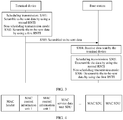
- the terminal device may add the C-RNTI of the terminal device to the MAC header corresponding to the data at the MAC layer.
- a format of a MAC packet assembly refer to FIG. 4 .
- step S303 After scrambling the to-be-sent data in step S301 or S302, the terminal device performs step S303.
- Step S303 The terminal device sends the scrambled to-be-sent data. Step S304 is performed.
- the terminal device may send the scrambled to-be-sent data on the frequency domain resource corresponding to the PUSCH index.
- the terminal device may send the scrambled to-be-sent data based on DCI indication including an uplink scheduling grant of the base station.
- step S304 The base station receives the data sent by the terminal device. In the scheduling transmission mode, step S305 is performed. In the non-scheduling transmission mode, step S306 is performed.
- the base station descrambles the data by using the second RNTI.
- the second RNTI may be the C-RNTI of the terminal device.
- the base station descrambles the received data by using the first RNTI.
- the first RNTI is the preset value, or the correspondence exists between the first RNTI and the specified frequency domain resource index.
- the base station may determine the first RNTI in either of the following two manners:
- the base station may record a mapping relationship between the frequency domain resource and the GL-RNTI, use the system message to notify the terminal device of the mapping relationship between the frequency domain resource and the GL-RNTI, and then allocate the frequency domain resource to the terminal device in a process in which the terminal device accesses the base station.
- the base station determines that the GL-RNTI corresponding to the allocated frequency domain resource is the first RNTI.
- Manner 2 The terminal device and the base station pre-agree on a value as the first RNTI, so that the base station performs descrambling by using the value when receiving the data that is based on the non-scheduling transmission.
- the base station may determine the first RNTI based on the PUSCH index of the specified frequency domain resource.
- the base station may perform a modulo operation on the PUSCH index of the specified frequency domain resource and the GL-RNTI number, where the GL-RNTI number may be pre-agreed on by the terminal device and the base station.
- the first RNTI is 170.
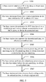
- the base station may perform demodulation and decoding processing on the data. For details, refer to FIG. 5 .
- S501 The base station removes a CP of the data, to obtain data without the CP.
- the base station performs fast Fourier transform (fast fourier transform, FFT) on the data without the CP, to obtain FFT data.
- FFT fast fourier transform
- the base station demodulates the FFT data based on a modulation and coding scheme corresponding to an MCS index, to obtain demodulated data.
- S504 The base station descrambles the demodulated data, to obtain descrambled data.
- S505 The base station performs inverse processing of rate matching on the descrambling data, to obtain data that exists before the rate matching.
- S506 The base station performs de-redundancy processing on the data that exists before the rate matching, to obtain de-redundant data.
- the de-redundancy processing may be inverse processing of tail-biting convolutional coding.
- the base station performs inverse check coding on the de-redundant data, to obtain original data.
- the inverse check coding may be specifically removing a CRC after the de-redundant data.
- That the base station descrambles the received data by using the first RNTI may be implemented in any one of the following three descrambling manners:
- the base station may use the first RNTI in a process of performing the inverse check coding in step S507.
- the base station may descramble a check bit of the de-redundant data by using the first RNTI, to obtain check coded data, and then perform inverse check coding on the check coded data.
- the base station may perform an exclusive OR operation on the first RNTI and the check bit of the de-redundant data.
- an exclusive OR operation refer to the method of performing the exclusive OR operation on the first RNTI and the CRC by the terminal device in the first scrambling manner. Details are not described herein again in this embodiment of this application.
- the base station may descramble the de-redundant data by using the first RNTI, to obtain check coded data, and then perform inverse check coding on the check coded data.
- the terminal device may perform an exclusive OR operation on the first RNTI and the de-redundant data. For details herein, refer to the method of performing the exclusive OR operation on the first RNTI and the CRC by the terminal device in the first scrambling manner. Details are not described herein again in this embodiment of this application.
- Second descrambling manner When the terminal device scrambles the to-be-sent data in the second scrambling manner, when performing step S504 of descrambling the demodulated data to obtain the descrambled data, the base station may demodulate the demodulated data by using the first RNTI.
- the base station may determine a pseudo-random sequence based on the first RNTI, and then descramble the demodulated data by using the pseudo-random sequence, to obtain descrambled data.
- c init is the pseudo-random sequence
- n RNTI is the first RNTI
- n f is a frame number
- n s is a slot number
- N ID Ncell is a cell identifier number, where a 1 , b 1 , c 1 , and d 1 are integers.
- b' is the demodulated data
- b is the descrambled data
- c init is the pseudo-random sequence.
- the base station may use the first RNTI in a process of performing inverse check coding in step S507; when performing step S504 of descrambling the demodulated data to obtain the descrambled data, the base station may demodulate the demodulated data by using the first RNTI.
- the base station uses the first RNTI in a process of performing the inverse check coding, refer to the first descrambling manner.
- the base station descrambles the demodulated data to obtain the descrambled data, refer to the method in the second descrambling manner. Details are not described herein again in this embodiment of this application.
- the base station may further obtain, from a MAC header of the data, a C-RNTI of the terminal device that sends the data.
- the terminal device when using the non-scheduling transmission mode, may scramble the to-be-sent data by using a preset value, and the base station may perform descrambling by using the preset value without performing the descrambling in a blind detection manner. Therefore, complexity of the descrambling may be effectively reduced.
- the terminal device when using the non-scheduling transmission mode, may further determine the first RNTI based on a frequency domain resource index carried in an indication message, and then perform scrambling by using the first RNTI.
- the base station may determine the first RNTI based on the frequency domain resource index, and then perform descrambling by using the first RNTI without performing the descrambling in a blind detection manner. Therefore, complexity of the descrambling may be effectively reduced.
- an embodiment of this application provides a terminal device, and the terminal device is specifically configured to implement the method described in the embodiment in FIG. 3 .
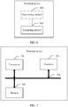
- a structure of the apparatus is shown in FIG. 6 and includes a scrambling module 601.
- the scrambling module 601 is configured to: when a transmission mode corresponding to the transmission mode identifier is non-scheduling transmission, scramble to-be-sent data by using a first RNTI, where the first RNTI is a preset value, or a correspondence exists between the first RNTI and a specified frequency domain resource index; or when the transmission mode corresponding to the transmission mode identifier is scheduling transmission, scramble the to-be-sent data by using a second RNTI, where the second RNTI is different from the first RNTI.
- the terminal device may further include a determining module 602, configured to: when the correspondence exists between the first RNTI and the frequency domain resource index, determine the first RNTI based on the specified frequency domain resource index.
- the determining module 602 may be specifically configured to perform an exclusive OR modulo operation on the specified frequency domain resource index and the preset value, to obtain the first RNTI.
- the scrambling module 601 may be specifically configured to: perform cyclic redundancy check CRC coding on the to-be-sent data, to obtain check coded data; perform redundancy information expansion processing on the check coded data, to obtain error-correction coded data; perform rate matching on the error-correction coded data, to obtain rate-matched data; determine a pseudo-random sequence based on the first RNTI; and scramble the rate-matched data by using the pseudo-random sequence.
- the scrambling module 601 may be specifically configured to: perform cyclic redundancy check CRC coding on the to-be-sent data, to obtain check coded data; and then scramble a check bit of the check coded data by using the first RNTI.
- the scrambling module 601 may be specifically configured to: perform cyclic redundancy check CRC coding on the to-be-sent data, to obtain check coded data; scramble a check bit of the check coded data by using the first RNTI, to obtain scrambled check coded data; perform redundancy information expansion processing on the scrambled check coded data, to obtain error-correction coded data; perform rate matching on the error-correction coded data, to obtain rate-matched data; determine a pseudo-random sequence based on the first RNTI; and scramble the rate-matched data by using the pseudo-random sequence.
- the scrambling module 601 when scrambling the check bit of the check coded data by using the first RNTI, performs an exclusive OR operation on the first RNTI and the check bit of the check coded data.
- division of modules is an example, and is merely logical function division. In an actual implementation, there may be another division manner.
- function modules in the embodiments of this application may be integrated into one processor, or each of the modules may exist alone physically, or two or more modules may be integrated into one module.
- the integrated module may be implemented in a form of hardware, or may be implemented in a form of a software function module.
- a terminal device may include a processor 702. Physical hardware corresponding to the foregoing module may be the processor 702.
- the processor 702 may be a central processing module (English: central processing unit, CPU for short), a digital processing module, or the like.
- the terminal device may further include a transceiver 701, and the processor 702 performs data receiving and sending with a base station by using the transceiver 701.
- the apparatus further includes a memory 703, configured to store a program executed by the processor 702.
- the memory 703 may be a nonvolatile memory, for example, a hard disk drive (hard disk drive, HDD) or a solid-state drive (solid-state drive, SSD), or may be a volatile memory (volatile memory), for example, a random-access memory (random-access memory, RAM).
- the memory 703 is any other medium that can be configured to carry or store expected program code that has an instruction or a data structure form and that can be accessed by a computer, but is not limited thereto.
- the processor 702 is configured to execute the program code stored in the memory 703, and is specifically configured to perform any method in the embodiment shown in FIG. 3 .
- the processor 702 is configured to execute the program code stored in the memory 703, and is specifically configured to perform any method in the embodiment shown in FIG. 3 .
- the processor 702 is configured to execute the program code stored in the memory 703, and is specifically configured to perform any method in the embodiment shown in FIG. 3 .
- the processor 702 is configured to execute the program code stored in the memory 703, and is specifically configured to perform any method in the embodiment shown in FIG. 3 .
- the processor 702 is configured to execute the program code stored in the memory 703, and is specifically configured to perform any method in the embodiment shown in FIG. 3 .
- FIG. 3 Details, refer to the method in the embodiment shown in FIG. 3 . Details are not described herein again in this application.
- a specific connection medium among the foregoing transceiver 701, processor 702, and memory 703 is not limited.
- the memory 703, the processor 702, and the transceiver 701 are connected to each other by using a bus 704 in FIG. 7 .
- the bus is represented by using a thick line in FIG. 7 , and a connection manner between other components is merely described as an example, and is not limited thereto.
- the bus may be classified into an address bus, a data bus, a control bus, and the like. For ease of representation, only one thick line is used to represent the bus in FIG. 7 , but this does not mean that there is only one bus or only one type of bus.
- An embodiment of the present invention further provides a chip.
- the chip includes the foregoing transceiver and the foregoing processor, and is configured to support a first relay device in implementing any method in the embodiment shown in FIG. 3 .
- An embodiment of this application further provides a computer-readable storage medium, configured to store a computer software instruction that needs to be executed for executing the foregoing processor.
- the computer-readable storage medium includes a program that needs to be executed for executing the foregoing processor.
- an embodiment of this application provides a base station, and the base station is specifically configured to implement the method described in the embodiment in FIG. 3 .
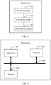
- a structure of the apparatus is shown in FIG. 8 and includes a receiving module 801 and a descrambling module 802.
- the receiving module 801 is configured to receive data sent by a terminal device.
- the descrambling module 802 is configured to: in a non-scheduling transmission mode, descramble the data by using a first RNTI, where the first RNTI is a preset value, or a correspondence exists between the first RNTI and a specified frequency domain resource index; or in the non-scheduling transmission mode, descramble the data by using a second RNTI.
- the base station may further include a determining module 803, configured to: when the correspondence exists between the first RNTI and the specified frequency domain resource index, determine the first RNTI based on the specified frequency domain resource index.
- the determining module 803 is specifically configured to perform a modulo operation on the specified frequency domain resource index and the preset value, to obtain the first RNTI.
- the descrambling module 802 may be specifically configured to: determine a pseudo-random sequence based on the first RNTI, and descramble the data by using the pseudo-random sequence.
- the descrambling module 802 may be specifically configured to: descramble the data, to obtain descrambled data; perform inverse processing of rate matching on the descrambled data, to obtain data that exits before the rate matching; perform de-redundancy processing on the data that exits before the rate matching, to obtain de-redundant data; descramble a check bit of the de-redundant data by using the first RNTI, to obtain check coded data; and perform inverse processing of cyclic redundancy check CRC coding on the check coded data.
- the descrambling module 802 may be specifically configured to: determine a pseudo-random sequence based on the first RNTI; descramble the data by using the pseudo-random sequence, to obtain descrambled data; perform inverse processing of rate matching on the descrambled data, to obtain data that exits before the rate matching; perform de-redundancy processing on the data that exits before the rate matching, to obtain de-redundant data; descramble a check bit of the de-redundant data by using the first RNTI, to obtain check coded data; and perform inverse processing of cyclic redundancy check CRC coding on the check coded data.
- the descrambling module 802 may be specifically configured to perform an exclusive OR operation on the first RNTI and the check bit of the de-redundant data.
- division of modules is an example, and is merely logical function division. In an actual implementation, there may be another division manner.
- function modules in the embodiments of this application may be integrated into one processor, or each of the modules may exist alone physically, or two or more modules may be integrated into one module.
- the integrated module may be implemented in a form of hardware, or may be implemented in a form of a software function module.
- a base station may include a processor 902. Physical hardware corresponding to the foregoing module may be the processor 902.
- the processor 902 may be a CPU, a digital processing module, or the like.
- the base station may further include a transceiver 901.
- the processor 902 performs data receiving and sending with a terminal device by using the transceiver 901.
- the apparatus further includes a memory 903, configured to store a program executed by the processor 902.
- the memory 903 may be a nonvolatile memory, for example, an HDD or an SSD, or may be a volatile memory, for example, an RAM.
- the memory 903 is any other medium that can be configured to carry or store expected program code that has an instruction or a data structure form and that can be accessed by a computer, but is not limited thereto.
- the processor 902 is configured to execute the program code stored in the memory 903, and is specifically configured to perform any method in the embodiment shown in FIG. 3 to FIG. 5 .
- the processor 902 is configured to execute the program code stored in the memory 903, and is specifically configured to perform any method in the embodiment shown in FIG. 3 to FIG. 5 .
- the processor 902 is configured to execute the program code stored in the memory 903, and is specifically configured to perform any method in the embodiment shown in FIG. 3 to FIG. 5 .
- the processor 902 is configured to execute the program code stored in the memory 903, and is specifically configured to perform any method in the embodiment shown in FIG. 3 to FIG. 5 .
- FIG. 3 to FIG. 5 Details are not described herein again in this application.
- a specific connection medium among the foregoing transceiver 901, processor 902, and memory 903 is not limited.
- the memory 903, the processor 902, and the transceiver 901 are connected to each other by using a bus 904 in FIG. 9 .
- the bus is represented by using a thick line in FIG. 9 , and a connection manner between other components is merely described as an example, and is not limited thereto.
- the bus may be classified into an address bus, a data bus, a control bus, and the like. For ease of representation, only one thick line is used to represent the bus in FIG. 9 , but this does not mean that there is only one bus or only one type of bus.
- An embodiment of the present invention further provides a chip.
- the chip includes the foregoing transceiver and the foregoing processor, and is configured to support a first relay device in implementing any method in the embodiment shown in FIG. 3 to FIG. 5 .
- An embodiment of this application further provides a computer-readable storage medium, configured to store a computer software instruction that needs to be executed for executing the foregoing processor.
- the computer-readable storage medium includes a program that needs to be executed for executing the foregoing processor.
- this application may be provided as a method, a system, or a computer program product. Therefore, this application may use a form of hardware only embodiments, software only embodiments, or embodiments with a combination of software and hardware. Moreover, this application may use a form of a computer program product that is implemented on one or more computer-usable storage media (including but not limited to a disk memory, a CD-ROM, an optical memory, and the like) that include computer usable program code.
- a computer-usable storage media including but not limited to a disk memory, a CD-ROM, an optical memory, and the like
- the computer program instructions may be provided for a general-purpose computer, a dedicated computer, an embedded processor, or a processor of any other programmable data processing device to generate a machine, so that the instructions executed by a computer or a processor of any other programmable data processing device generate an apparatus for implementing a specific function in one or more processes in the flowcharts and/or in one or more blocks in the block diagrams.
- the computer program instructions may be stored in a computer-readable memory that can instruct the computer or any other programmable data processing device to work in a specific manner, so that the instructions stored in the computer-readable memory generate an artifact that includes an instruction apparatus.
- the instruction apparatus implements a specific function in one or more processes in the flowcharts and/or in one or more blocks in the block diagrams.
- the computer program instructions may be loaded onto a computer or another programmable data processing device, so that a series of operations and steps are performed on the computer or the another programmable device, thereby generating computer-implemented processing. Therefore, the instructions executed on the computer or the another programmable device provide steps for implementing a specific function in one or more processes in the flowcharts and/or in one or more blocks in the block diagrams.
Landscapes
- Engineering & Computer Science (AREA)
- Signal Processing (AREA)
- Computer Networks & Wireless Communication (AREA)
- Databases & Information Systems (AREA)
- Mobile Radio Communication Systems (AREA)
Applications Claiming Priority (1)
| Application Number | Priority Date | Filing Date | Title |
|---|---|---|---|
| PCT/CN2018/075632 WO2019153142A1 (fr) | 2018-02-07 | 2018-02-07 | Procédé et appareil de transmission de canal |
Publications (3)
| Publication Number | Publication Date |
|---|---|
| EP3720161A1 true EP3720161A1 (fr) | 2020-10-07 |
| EP3720161A4 EP3720161A4 (fr) | 2020-12-16 |
| EP3720161B1 EP3720161B1 (fr) | 2024-08-07 |
Family
ID=67547790
Family Applications (1)
| Application Number | Title | Priority Date | Filing Date |
|---|---|---|---|
| EP18905333.3A Active EP3720161B1 (fr) | 2018-02-07 | 2018-02-07 | Procédés et appareils de transmission de canal |
Country Status (4)
| Country | Link |
|---|---|
| US (1) | US20200359364A1 (fr) |
| EP (1) | EP3720161B1 (fr) |
| CN (1) | CN111567074B (fr) |
| WO (1) | WO2019153142A1 (fr) |
Families Citing this family (4)
| Publication number | Priority date | Publication date | Assignee | Title |
|---|---|---|---|---|
| KR102736771B1 (ko) * | 2018-02-08 | 2024-12-02 | 삼성전자 주식회사 | 물리적 채널 송신 방법 및 사용자 장치, 릴레이 송신 방법 및 사용자 장치 |
| US11812483B2 (en) * | 2019-02-12 | 2023-11-07 | Qualcomm Incorporated | Support of proprietary features in wireless communications networks |
| CN112702787B (zh) * | 2019-10-22 | 2022-12-16 | 海能达通信股份有限公司 | 一种基于扰频的通信方法、装置及存储介质 |
| CN114071736B (zh) * | 2020-08-06 | 2025-10-31 | 华为技术有限公司 | 传输控制信令的方法和装置 |
Family Cites Families (10)
| Publication number | Priority date | Publication date | Assignee | Title |
|---|---|---|---|---|
| US9161212B2 (en) * | 2006-10-03 | 2015-10-13 | Qualcomm Incorporated | Method and apparatus for re-synchronizing of temporary UE IDs in a wireless communication system |
| CN101909360A (zh) * | 2009-06-03 | 2010-12-08 | 中国移动通信集团公司 | 多载波调度指示方法及设备、多载波调度方法及设备 |
| CN101715237B (zh) * | 2009-11-05 | 2015-09-16 | 中兴通讯股份有限公司 | 基于竞争的上行传输方法及装置 |
| EP2945445B1 (fr) * | 2013-02-05 | 2017-09-13 | Huawei Technologies Co., Ltd. | Procédé d'indication de porteuse, équipement d'utilisateur, et station de base |
| WO2015142271A1 (fr) * | 2014-03-19 | 2015-09-24 | Telefonaktiebolaget L M Ericsson (Publ) | Procédé, station de base et dispositif sans fil pour prendre en charge des communications radio |
| WO2016008537A1 (fr) * | 2014-07-18 | 2016-01-21 | Huawei Technologies Co.,Ltd | Dispositif utilisateur, nœud de réseau et procédés associés |
| CN107409413B (zh) * | 2015-04-15 | 2021-06-04 | 苹果公司 | 蜂窝网络中用于机器类型通信的方法和装置 |
| US9967910B2 (en) * | 2016-03-03 | 2018-05-08 | Huawei Technologies Co., Ltd. | System and method for establishing a D2D communication group |
| CN107371270B (zh) * | 2016-05-13 | 2021-11-09 | 中兴通讯股份有限公司 | 一种传输方法、设备和系统 |
| GB2565764A (en) * | 2017-08-10 | 2019-02-27 | Nec Corp | Communication system |
-
2018
- 2018-02-07 CN CN201880085976.XA patent/CN111567074B/zh active Active
- 2018-02-07 WO PCT/CN2018/075632 patent/WO2019153142A1/fr not_active Ceased
- 2018-02-07 EP EP18905333.3A patent/EP3720161B1/fr active Active
-
2020
- 2020-07-30 US US16/943,740 patent/US20200359364A1/en not_active Abandoned
Also Published As
| Publication number | Publication date |
|---|---|
| CN111567074A (zh) | 2020-08-21 |
| CN111567074B (zh) | 2022-02-18 |
| WO2019153142A1 (fr) | 2019-08-15 |
| US20200359364A1 (en) | 2020-11-12 |
| EP3720161B1 (fr) | 2024-08-07 |
| EP3720161A4 (fr) | 2020-12-16 |
Similar Documents
| Publication | Publication Date | Title |
|---|---|---|
| EP3468245B1 (fr) | Procédé et appareil de traitement de signaux | |
| US20230389034A1 (en) | Communication method, apparatus, and system | |
| EP3902182A1 (fr) | Procédé et appareil de transmission de canal de liaison descendante | |
| EP3324696B1 (fr) | Procédé de transmission d'informations, station de base et équipement utilisateur | |
| US20200359364A1 (en) | Channel transmission method and apparatus | |
| US12095552B2 (en) | Message transmission method and device | |
| US10264572B2 (en) | Method and device for scrambling sequence configuration, user equipment, and base station | |
| US10631340B2 (en) | Random access method and apparatus, base station, and UE | |
| JP2018512774A (ja) | アップリンクデータ伝送の方法および装置 | |
| EP3621275B1 (fr) | Procédé de transmission et procédé de réception de signaux de diffusion, dispositif de réseau et dispositif terminal | |
| CN104683969B (zh) | 一种ue中的方法和用户设备 | |
| EP3402240B1 (fr) | Procédé de détection d'informations de commande de liaison descendante, procédé et dispositif pour transmettre des informations de commande de liaison descendante | |
| CN114616783A (zh) | 用于物理上行链路共享信道的解调参考信号的可配置下行链路控制信息的用户装备、基站和方法 | |
| EP3589048A1 (fr) | Procédé et appareil d'envoi de données, et procédé et appareil de réception de données | |
| US11381340B2 (en) | Data transmission method and apparatus and storage medium | |
| US11206684B2 (en) | Method and device for sending and receiving preamble sequence of physical random access channel | |
| CN110035528B (zh) | 一种通信方法、装置以及系统 | |
| US20200178234A1 (en) | Information Sending Method And Device | |
| EP3591846B1 (fr) | Procédé et dispositif de codage à code polaire et procédé et dispositif de décodage à code polaire | |
| US12101747B2 (en) | Communication method and apparatus | |
| US20240089060A1 (en) | Reference signal port indication techniques | |
| EP3667960A1 (fr) | Procédés et dispositifs d'envoi et de réception de signaux | |
| WO2023160677A1 (fr) | Procédé de communication et appareil associé | |
| CN114600414B (zh) | 用于物理下行链路共享信道的解调参考信号的可配置下行链路控制信息的用户装备、基站和方法 | |
| CN111294154B (zh) | 信息传输方法和设备 |
Legal Events
| Date | Code | Title | Description |
|---|---|---|---|
| STAA | Information on the status of an ep patent application or granted ep patent |
Free format text: STATUS: THE INTERNATIONAL PUBLICATION HAS BEEN MADE |
|
| PUAI | Public reference made under article 153(3) epc to a published international application that has entered the european phase |
Free format text: ORIGINAL CODE: 0009012 |
|
| STAA | Information on the status of an ep patent application or granted ep patent |
Free format text: STATUS: REQUEST FOR EXAMINATION WAS MADE |
|
| 17P | Request for examination filed |
Effective date: 20200702 |
|
| AK | Designated contracting states |
Kind code of ref document: A1 Designated state(s): AL AT BE BG CH CY CZ DE DK EE ES FI FR GB GR HR HU IE IS IT LI LT LU LV MC MK MT NL NO PL PT RO RS SE SI SK SM TR |
|
| AX | Request for extension of the european patent |
Extension state: BA ME |
|
| A4 | Supplementary search report drawn up and despatched |
Effective date: 20201117 |
|
| RIC1 | Information provided on ipc code assigned before grant |
Ipc: H04W 72/00 20090101ALI20201111BHEP Ipc: H04W 72/12 20090101ALI20201111BHEP Ipc: H04W 8/26 20090101AFI20201111BHEP |
|
| DAV | Request for validation of the european patent (deleted) | ||
| DAX | Request for extension of the european patent (deleted) | ||
| STAA | Information on the status of an ep patent application or granted ep patent |
Free format text: STATUS: EXAMINATION IS IN PROGRESS |
|
| 17Q | First examination report despatched |
Effective date: 20220510 |
|
| GRAP | Despatch of communication of intention to grant a patent |
Free format text: ORIGINAL CODE: EPIDOSNIGR1 |
|
| STAA | Information on the status of an ep patent application or granted ep patent |
Free format text: STATUS: GRANT OF PATENT IS INTENDED |
|
| RIC1 | Information provided on ipc code assigned before grant |
Ipc: H04L 5/00 20060101ALI20240214BHEP Ipc: H04L 1/00 20060101ALI20240214BHEP Ipc: H04W 72/12 20090101ALI20240214BHEP Ipc: H04W 72/00 20090101ALI20240214BHEP Ipc: H04W 8/26 20090101AFI20240214BHEP |
|
| INTG | Intention to grant announced |
Effective date: 20240315 |
|
| GRAS | Grant fee paid |
Free format text: ORIGINAL CODE: EPIDOSNIGR3 |
|
| GRAA | (expected) grant |
Free format text: ORIGINAL CODE: 0009210 |
|
| STAA | Information on the status of an ep patent application or granted ep patent |
Free format text: STATUS: THE PATENT HAS BEEN GRANTED |
|
| AK | Designated contracting states |
Kind code of ref document: B1 Designated state(s): AL AT BE BG CH CY CZ DE DK EE ES FI FR GB GR HR HU IE IS IT LI LT LU LV MC MK MT NL NO PL PT RO RS SE SI SK SM TR |
|
| REG | Reference to a national code |
Ref country code: GB Ref legal event code: FG4D |
|
| REG | Reference to a national code |
Ref country code: CH Ref legal event code: EP |
|
| REG | Reference to a national code |
Ref country code: DE Ref legal event code: R096 Ref document number: 602018072951 Country of ref document: DE |
|
| REG | Reference to a national code |
Ref country code: IE Ref legal event code: FG4D |
|
| REG | Reference to a national code |
Ref country code: LT Ref legal event code: MG9D |
|
| REG | Reference to a national code |
Ref country code: NL Ref legal event code: MP Effective date: 20240807 |
|
| PG25 | Lapsed in a contracting state [announced via postgrant information from national office to epo] |
Ref country code: NO Free format text: LAPSE BECAUSE OF FAILURE TO SUBMIT A TRANSLATION OF THE DESCRIPTION OR TO PAY THE FEE WITHIN THE PRESCRIBED TIME-LIMIT Effective date: 20241107 |
|
| REG | Reference to a national code |
Ref country code: AT Ref legal event code: MK05 Ref document number: 1712232 Country of ref document: AT Kind code of ref document: T Effective date: 20240807 |
|
| PG25 | Lapsed in a contracting state [announced via postgrant information from national office to epo] |
Ref country code: PT Free format text: LAPSE BECAUSE OF FAILURE TO SUBMIT A TRANSLATION OF THE DESCRIPTION OR TO PAY THE FEE WITHIN THE PRESCRIBED TIME-LIMIT Effective date: 20241209 Ref country code: NL Free format text: LAPSE BECAUSE OF FAILURE TO SUBMIT A TRANSLATION OF THE DESCRIPTION OR TO PAY THE FEE WITHIN THE PRESCRIBED TIME-LIMIT Effective date: 20240807 Ref country code: GR Free format text: LAPSE BECAUSE OF FAILURE TO SUBMIT A TRANSLATION OF THE DESCRIPTION OR TO PAY THE FEE WITHIN THE PRESCRIBED TIME-LIMIT Effective date: 20241108 Ref country code: PL Free format text: LAPSE BECAUSE OF FAILURE TO SUBMIT A TRANSLATION OF THE DESCRIPTION OR TO PAY THE FEE WITHIN THE PRESCRIBED TIME-LIMIT Effective date: 20240807 Ref country code: FI Free format text: LAPSE BECAUSE OF FAILURE TO SUBMIT A TRANSLATION OF THE DESCRIPTION OR TO PAY THE FEE WITHIN THE PRESCRIBED TIME-LIMIT Effective date: 20240807 |
|
| PG25 | Lapsed in a contracting state [announced via postgrant information from national office to epo] |
Ref country code: BG Free format text: LAPSE BECAUSE OF FAILURE TO SUBMIT A TRANSLATION OF THE DESCRIPTION OR TO PAY THE FEE WITHIN THE PRESCRIBED TIME-LIMIT Effective date: 20240807 |
|
| PG25 | Lapsed in a contracting state [announced via postgrant information from national office to epo] |
Ref country code: LV Free format text: LAPSE BECAUSE OF FAILURE TO SUBMIT A TRANSLATION OF THE DESCRIPTION OR TO PAY THE FEE WITHIN THE PRESCRIBED TIME-LIMIT Effective date: 20240807 |
|
| PG25 | Lapsed in a contracting state [announced via postgrant information from national office to epo] |
Ref country code: IS Free format text: LAPSE BECAUSE OF FAILURE TO SUBMIT A TRANSLATION OF THE DESCRIPTION OR TO PAY THE FEE WITHIN THE PRESCRIBED TIME-LIMIT Effective date: 20241207 Ref country code: AT Free format text: LAPSE BECAUSE OF FAILURE TO SUBMIT A TRANSLATION OF THE DESCRIPTION OR TO PAY THE FEE WITHIN THE PRESCRIBED TIME-LIMIT Effective date: 20240807 |
|
| PG25 | Lapsed in a contracting state [announced via postgrant information from national office to epo] |
Ref country code: HR Free format text: LAPSE BECAUSE OF FAILURE TO SUBMIT A TRANSLATION OF THE DESCRIPTION OR TO PAY THE FEE WITHIN THE PRESCRIBED TIME-LIMIT Effective date: 20240807 |
|
| PG25 | Lapsed in a contracting state [announced via postgrant information from national office to epo] |
Ref country code: RS Free format text: LAPSE BECAUSE OF FAILURE TO SUBMIT A TRANSLATION OF THE DESCRIPTION OR TO PAY THE FEE WITHIN THE PRESCRIBED TIME-LIMIT Effective date: 20241107 Ref country code: ES Free format text: LAPSE BECAUSE OF FAILURE TO SUBMIT A TRANSLATION OF THE DESCRIPTION OR TO PAY THE FEE WITHIN THE PRESCRIBED TIME-LIMIT Effective date: 20240807 |
|
| PG25 | Lapsed in a contracting state [announced via postgrant information from national office to epo] |
Ref country code: RS Free format text: LAPSE BECAUSE OF FAILURE TO SUBMIT A TRANSLATION OF THE DESCRIPTION OR TO PAY THE FEE WITHIN THE PRESCRIBED TIME-LIMIT Effective date: 20241107 Ref country code: PT Free format text: LAPSE BECAUSE OF FAILURE TO SUBMIT A TRANSLATION OF THE DESCRIPTION OR TO PAY THE FEE WITHIN THE PRESCRIBED TIME-LIMIT Effective date: 20241209 Ref country code: PL Free format text: LAPSE BECAUSE OF FAILURE TO SUBMIT A TRANSLATION OF THE DESCRIPTION OR TO PAY THE FEE WITHIN THE PRESCRIBED TIME-LIMIT Effective date: 20240807 Ref country code: NO Free format text: LAPSE BECAUSE OF FAILURE TO SUBMIT A TRANSLATION OF THE DESCRIPTION OR TO PAY THE FEE WITHIN THE PRESCRIBED TIME-LIMIT Effective date: 20241107 Ref country code: NL Free format text: LAPSE BECAUSE OF FAILURE TO SUBMIT A TRANSLATION OF THE DESCRIPTION OR TO PAY THE FEE WITHIN THE PRESCRIBED TIME-LIMIT Effective date: 20240807 Ref country code: LV Free format text: LAPSE BECAUSE OF FAILURE TO SUBMIT A TRANSLATION OF THE DESCRIPTION OR TO PAY THE FEE WITHIN THE PRESCRIBED TIME-LIMIT Effective date: 20240807 Ref country code: IS Free format text: LAPSE BECAUSE OF FAILURE TO SUBMIT A TRANSLATION OF THE DESCRIPTION OR TO PAY THE FEE WITHIN THE PRESCRIBED TIME-LIMIT Effective date: 20241207 Ref country code: HR Free format text: LAPSE BECAUSE OF FAILURE TO SUBMIT A TRANSLATION OF THE DESCRIPTION OR TO PAY THE FEE WITHIN THE PRESCRIBED TIME-LIMIT Effective date: 20240807 Ref country code: GR Free format text: LAPSE BECAUSE OF FAILURE TO SUBMIT A TRANSLATION OF THE DESCRIPTION OR TO PAY THE FEE WITHIN THE PRESCRIBED TIME-LIMIT Effective date: 20241108 Ref country code: FI Free format text: LAPSE BECAUSE OF FAILURE TO SUBMIT A TRANSLATION OF THE DESCRIPTION OR TO PAY THE FEE WITHIN THE PRESCRIBED TIME-LIMIT Effective date: 20240807 Ref country code: ES Free format text: LAPSE BECAUSE OF FAILURE TO SUBMIT A TRANSLATION OF THE DESCRIPTION OR TO PAY THE FEE WITHIN THE PRESCRIBED TIME-LIMIT Effective date: 20240807 Ref country code: BG Free format text: LAPSE BECAUSE OF FAILURE TO SUBMIT A TRANSLATION OF THE DESCRIPTION OR TO PAY THE FEE WITHIN THE PRESCRIBED TIME-LIMIT Effective date: 20240807 Ref country code: AT Free format text: LAPSE BECAUSE OF FAILURE TO SUBMIT A TRANSLATION OF THE DESCRIPTION OR TO PAY THE FEE WITHIN THE PRESCRIBED TIME-LIMIT Effective date: 20240807 |
|
| PG25 | Lapsed in a contracting state [announced via postgrant information from national office to epo] |
Ref country code: DK Free format text: LAPSE BECAUSE OF FAILURE TO SUBMIT A TRANSLATION OF THE DESCRIPTION OR TO PAY THE FEE WITHIN THE PRESCRIBED TIME-LIMIT Effective date: 20240807 Ref country code: SM Free format text: LAPSE BECAUSE OF FAILURE TO SUBMIT A TRANSLATION OF THE DESCRIPTION OR TO PAY THE FEE WITHIN THE PRESCRIBED TIME-LIMIT Effective date: 20240807 Ref country code: RO Free format text: LAPSE BECAUSE OF FAILURE TO SUBMIT A TRANSLATION OF THE DESCRIPTION OR TO PAY THE FEE WITHIN THE PRESCRIBED TIME-LIMIT Effective date: 20240807 |
|
| PG25 | Lapsed in a contracting state [announced via postgrant information from national office to epo] |
Ref country code: EE Free format text: LAPSE BECAUSE OF FAILURE TO SUBMIT A TRANSLATION OF THE DESCRIPTION OR TO PAY THE FEE WITHIN THE PRESCRIBED TIME-LIMIT Effective date: 20240807 |
|
| PG25 | Lapsed in a contracting state [announced via postgrant information from national office to epo] |
Ref country code: CZ Free format text: LAPSE BECAUSE OF FAILURE TO SUBMIT A TRANSLATION OF THE DESCRIPTION OR TO PAY THE FEE WITHIN THE PRESCRIBED TIME-LIMIT Effective date: 20240807 |
|
| PG25 | Lapsed in a contracting state [announced via postgrant information from national office to epo] |
Ref country code: SK Free format text: LAPSE BECAUSE OF FAILURE TO SUBMIT A TRANSLATION OF THE DESCRIPTION OR TO PAY THE FEE WITHIN THE PRESCRIBED TIME-LIMIT Effective date: 20240807 |
|
| REG | Reference to a national code |
Ref country code: DE Ref legal event code: R097 Ref document number: 602018072951 Country of ref document: DE |
|
| PLBE | No opposition filed within time limit |
Free format text: ORIGINAL CODE: 0009261 |
|
| STAA | Information on the status of an ep patent application or granted ep patent |
Free format text: STATUS: NO OPPOSITION FILED WITHIN TIME LIMIT |
|
| 26N | No opposition filed |
Effective date: 20250508 |
|
| PG25 | Lapsed in a contracting state [announced via postgrant information from national office to epo] |
Ref country code: SE Free format text: LAPSE BECAUSE OF FAILURE TO SUBMIT A TRANSLATION OF THE DESCRIPTION OR TO PAY THE FEE WITHIN THE PRESCRIBED TIME-LIMIT Effective date: 20240807 |
|
| PG25 | Lapsed in a contracting state [announced via postgrant information from national office to epo] |
Ref country code: MC Free format text: LAPSE BECAUSE OF FAILURE TO SUBMIT A TRANSLATION OF THE DESCRIPTION OR TO PAY THE FEE WITHIN THE PRESCRIBED TIME-LIMIT Effective date: 20240807 |
|
| REG | Reference to a national code |
Ref country code: CH Ref legal event code: PL |
|
| PG25 | Lapsed in a contracting state [announced via postgrant information from national office to epo] |
Ref country code: LU Free format text: LAPSE BECAUSE OF NON-PAYMENT OF DUE FEES Effective date: 20250207 |
|
| PG25 | Lapsed in a contracting state [announced via postgrant information from national office to epo] |
Ref country code: CH Free format text: LAPSE BECAUSE OF NON-PAYMENT OF DUE FEES Effective date: 20250228 |
|
| GBPC | Gb: european patent ceased through non-payment of renewal fee |
Effective date: 20250207 |
|
| REG | Reference to a national code |
Ref country code: BE Ref legal event code: MM Effective date: 20250228 |
|
| PG25 | Lapsed in a contracting state [announced via postgrant information from national office to epo] |
Ref country code: GB Free format text: LAPSE BECAUSE OF NON-PAYMENT OF DUE FEES Effective date: 20250207 |
|
| PG25 | Lapsed in a contracting state [announced via postgrant information from national office to epo] |
Ref country code: FR Free format text: LAPSE BECAUSE OF NON-PAYMENT OF DUE FEES Effective date: 20250228 |
|
| PG25 | Lapsed in a contracting state [announced via postgrant information from national office to epo] |
Ref country code: BE Free format text: LAPSE BECAUSE OF NON-PAYMENT OF DUE FEES Effective date: 20250228 |
|
| PG25 | Lapsed in a contracting state [announced via postgrant information from national office to epo] |
Ref country code: IE Free format text: LAPSE BECAUSE OF NON-PAYMENT OF DUE FEES Effective date: 20250207 |
|
| PG25 | Lapsed in a contracting state [announced via postgrant information from national office to epo] |
Ref country code: IT Free format text: LAPSE BECAUSE OF FAILURE TO SUBMIT A TRANSLATION OF THE DESCRIPTION OR TO PAY THE FEE WITHIN THE PRESCRIBED TIME-LIMIT Effective date: 20240807 |
|
| PGFP | Annual fee paid to national office [announced via postgrant information from national office to epo] |
Ref country code: DE Payment date: 20251230 Year of fee payment: 9 |