EP3720177B1 - Procédé de configuration et dispositif de signal de référence de sondage (srs) - Google Patents
Procédé de configuration et dispositif de signal de référence de sondage (srs) Download PDFInfo
- Publication number
- EP3720177B1 EP3720177B1 EP18899154.1A EP18899154A EP3720177B1 EP 3720177 B1 EP3720177 B1 EP 3720177B1 EP 18899154 A EP18899154 A EP 18899154A EP 3720177 B1 EP3720177 B1 EP 3720177B1
- Authority
- EP
- European Patent Office
- Prior art keywords
- srs
- slot
- dci
- symbol
- srs resource
- Prior art date
- Legal status (The legal status is an assumption and is not a legal conclusion. Google has not performed a legal analysis and makes no representation as to the accuracy of the status listed.)
- Active
Links
Images


Classifications
-
- H—ELECTRICITY
- H04—ELECTRIC COMMUNICATION TECHNIQUE
- H04L—TRANSMISSION OF DIGITAL INFORMATION, e.g. TELEGRAPHIC COMMUNICATION
- H04L25/00—Baseband systems
- H04L25/02—Details ; arrangements for supplying electrical power along data transmission lines
- H04L25/0202—Channel estimation
- H04L25/0224—Channel estimation using sounding signals
- H04L25/0226—Channel estimation using sounding signals sounding signals per se
-
- H—ELECTRICITY
- H04—ELECTRIC COMMUNICATION TECHNIQUE
- H04L—TRANSMISSION OF DIGITAL INFORMATION, e.g. TELEGRAPHIC COMMUNICATION
- H04L5/00—Arrangements affording multiple use of the transmission path
- H04L5/003—Arrangements for allocating sub-channels of the transmission path
- H04L5/0048—Allocation of pilot signals, i.e. of signals known to the receiver
-
- H—ELECTRICITY
- H04—ELECTRIC COMMUNICATION TECHNIQUE
- H04B—TRANSMISSION
- H04B7/00—Radio transmission systems, i.e. using radiation field
- H04B7/02—Diversity systems; Multi-antenna system, i.e. transmission or reception using multiple antennas
- H04B7/04—Diversity systems; Multi-antenna system, i.e. transmission or reception using multiple antennas using two or more spaced independent antennas
- H04B7/0408—Diversity systems; Multi-antenna system, i.e. transmission or reception using multiple antennas using two or more spaced independent antennas using two or more beams, i.e. beam diversity
-
- H—ELECTRICITY
- H04—ELECTRIC COMMUNICATION TECHNIQUE
- H04B—TRANSMISSION
- H04B7/00—Radio transmission systems, i.e. using radiation field
- H04B7/02—Diversity systems; Multi-antenna system, i.e. transmission or reception using multiple antennas
- H04B7/04—Diversity systems; Multi-antenna system, i.e. transmission or reception using multiple antennas using two or more spaced independent antennas
- H04B7/06—Diversity systems; Multi-antenna system, i.e. transmission or reception using multiple antennas using two or more spaced independent antennas at the transmitting station
- H04B7/0613—Diversity systems; Multi-antenna system, i.e. transmission or reception using multiple antennas using two or more spaced independent antennas at the transmitting station using simultaneous transmission
- H04B7/0615—Diversity systems; Multi-antenna system, i.e. transmission or reception using multiple antennas using two or more spaced independent antennas at the transmitting station using simultaneous transmission of weighted versions of same signal
- H04B7/0617—Diversity systems; Multi-antenna system, i.e. transmission or reception using multiple antennas using two or more spaced independent antennas at the transmitting station using simultaneous transmission of weighted versions of same signal for beam forming
-
- H—ELECTRICITY
- H04—ELECTRIC COMMUNICATION TECHNIQUE
- H04L—TRANSMISSION OF DIGITAL INFORMATION, e.g. TELEGRAPHIC COMMUNICATION
- H04L5/00—Arrangements affording multiple use of the transmission path
- H04L5/0001—Arrangements for dividing the transmission path
- H04L5/0014—Three-dimensional division
- H04L5/0023—Time-frequency-space
-
- H—ELECTRICITY
- H04—ELECTRIC COMMUNICATION TECHNIQUE
- H04L—TRANSMISSION OF DIGITAL INFORMATION, e.g. TELEGRAPHIC COMMUNICATION
- H04L5/00—Arrangements affording multiple use of the transmission path
- H04L5/003—Arrangements for allocating sub-channels of the transmission path
- H04L5/0048—Allocation of pilot signals, i.e. of signals known to the receiver
- H04L5/005—Allocation of pilot signals, i.e. of signals known to the receiver of common pilots, i.e. pilots destined for multiple users or terminals
-
- H—ELECTRICITY
- H04—ELECTRIC COMMUNICATION TECHNIQUE
- H04L—TRANSMISSION OF DIGITAL INFORMATION, e.g. TELEGRAPHIC COMMUNICATION
- H04L5/00—Arrangements affording multiple use of the transmission path
- H04L5/003—Arrangements for allocating sub-channels of the transmission path
- H04L5/0053—Allocation of signalling, i.e. of overhead other than pilot signals
-
- H—ELECTRICITY
- H04—ELECTRIC COMMUNICATION TECHNIQUE
- H04L—TRANSMISSION OF DIGITAL INFORMATION, e.g. TELEGRAPHIC COMMUNICATION
- H04L5/00—Arrangements affording multiple use of the transmission path
- H04L5/003—Arrangements for allocating sub-channels of the transmission path
- H04L5/0053—Allocation of signalling, i.e. of overhead other than pilot signals
- H04L5/0055—Physical resource allocation for ACK/NACK
-
- H—ELECTRICITY
- H04—ELECTRIC COMMUNICATION TECHNIQUE
- H04L—TRANSMISSION OF DIGITAL INFORMATION, e.g. TELEGRAPHIC COMMUNICATION
- H04L5/00—Arrangements affording multiple use of the transmission path
- H04L5/003—Arrangements for allocating sub-channels of the transmission path
- H04L5/0078—Timing of allocation
-
- H—ELECTRICITY
- H04—ELECTRIC COMMUNICATION TECHNIQUE
- H04L—TRANSMISSION OF DIGITAL INFORMATION, e.g. TELEGRAPHIC COMMUNICATION
- H04L5/00—Arrangements affording multiple use of the transmission path
- H04L5/0091—Signalling for the administration of the divided path, e.g. signalling of configuration information
- H04L5/0094—Indication of how sub-channels of the path are allocated
-
- H—ELECTRICITY
- H04—ELECTRIC COMMUNICATION TECHNIQUE
- H04W—WIRELESS COMMUNICATION NETWORKS
- H04W72/00—Local resource management
- H04W72/04—Wireless resource allocation
- H04W72/044—Wireless resource allocation based on the type of the allocated resource
- H04W72/0446—Resources in time domain, e.g. slots or frames
-
- H—ELECTRICITY
- H04—ELECTRIC COMMUNICATION TECHNIQUE
- H04W—WIRELESS COMMUNICATION NETWORKS
- H04W72/00—Local resource management
- H04W72/20—Control channels or signalling for resource management
- H04W72/23—Control channels or signalling for resource management in the downlink direction of a wireless link, i.e. towards a terminal
Definitions
- This application relates to the field of wireless communication technologies, and in particular, to a sounding reference signal SRS transmission method and an apparatus in a wireless communications system.
- UE user equipment
- SRS Sounding Reference Signal
- the UE may transmit the SRS on a resource configured by the base station. After receiving the SRS, the base station obtains the uplink channel state information.
- Reference R1 discusses design, options for sounding reference signals.
- R2 provides a method of supporting uplink aperiodic sounding reference signal transmission in wireless communication networks.
- This specification describes an SRS transmission method, and a time for transmitting an SRS may be determined.
- this application provides an SRS transmission method.
- the method includes: receiving, by user equipment UE, SRS resource configuration information sent by a base station; receiving, by the UE, downlink control information DCI sent by the base station; and sending, by the UE, an SRS in a determined slot and symbol, where the determined symbol is determined by the UE based on the SRS resource configuration information. Therefore, the UE may determine, based on the SRS resource configuration, the symbol for sending the SRS, and may further determine the slot for sending the SRS, thereby resolving a problem of when to transmit the SRS.
- the DCI received by the UE is downlink DCI, and the UE may determine, based on current k0, k1, k2, and some other parameters, a time for transmitting the SRS.
- the UE may determine, based on current k0, k1, k2, and some other parameters, a time for transmitting the SRS.
- the DCI received by the UE is uplink DCI, and the UE may determine, based on current k2 and ⁇ UL, a time for transmitting the SRS.
- the UE may determine, based on current k2 and ⁇ UL, a time for transmitting the SRS.
- signaling overheads can be reduced, and the SRS can be transmitted more flexibly.
- the DCI may include content used to indicate a k value.
- a field in the DCI indicates the k value, and one of a plurality of candidate values may be selected as the k value.
- the DCI includes content used to indicate that the k value is a value in a candidate set of k values.
- the candidate set of the k values may be a candidate set of k0 values, a candidate set of k1 values, or a candidate set of k2 values, or the candidate set of the k values is configured by using higher layer signaling.
- the UE may determine, based on the indication of the k value in the DCI or the higher layer signaling, the time for transmitting the SRS, so that signaling overheads can be reduced, and the SRS can be transmitted more flexibly.
- the candidate set of the k0 values is a candidate set of a quantity of slots between the DCI and a first slot in which downlink transmission scheduled by the DCI is located
- the candidate set of the k1 values is a candidate set of a quantity of slots between an end of the downlink transmission scheduled by the DCI and an uplink feedback corresponding to the downlink transmission
- the candidate set of the k2 values is a candidate set of slot intervals between the DCI and uplink transmission scheduled by the DCI.
- the SRS resource configuration information includes information used to indicate the symbol for transmitting the SRS
- the information used to indicate the symbol for transmitting the SRS is used to indicate content including a location of a start symbol S of a resource, in one slot, for transmitting the SRS, a quantity N of symbols of the resource for transmitting the SRS, and a repetition factor r of the resource for transmitting the SRS, and any two of S, N, or r are jointly encoded, or S, N, and r are jointly encoded. Joint encoding performed on any two or three of S, N, and r meets a specific constraint relationship, so that overheads can be effectively reduced, and incorrect configuration can be avoided.
- the SRS resource configuration information includes configuration information used to indicate an SRS resource set, the SRS resource set includes one or more SRS resources, and the SRS resource configuration information further includes information used to indicate that the SRS resource set has at least two of four functions: beam management (beam management), antenna polling (antenna switching), codebook (codebook)-based transmission, and non-codebook (non-codebook)-based transmission.
- beam management beam management
- antenna polling antenna polling
- codebook codebook
- non-codebook non-codebook
- this application provides an SRS transmission method.
- a base station sends SRS resource configuration information to user equipment UE; the base station sends downlink control information DCI to the UE; and the base station receives an SRS sent by the UE based on the SRS resource configuration information. Therefore, after receiving the SRS resource configuration information and the DCI that are transmitted by the base station, the UE may determine when to transmit the SRS.
- the base station sends the DCI to the UE in an n th slot, and receives the SRS in an (n+k) th slot.
- the DCI includes content used to indicate a k value, or the DCI includes content used to indicate that the k value is one of a candidate set of k values, and the candidate set of the k values is one of the following: a candidate set of k0 values, a candidate set of k1 values, and a candidate set of k2 values.
- the candidate set of the k0 values is a candidate set of a quantity of slots between the DCI and a first slot in which downlink transmission scheduled by the DCI is located.
- the candidate set of the k1 values is a candidate set of a quantity of slots between an end of the downlink transmission scheduled by the DCI and an uplink feedback corresponding to the downlink transmission.
- the candidate set of the k2 values is a candidate set of slot intervals between the DCI and uplink transmission scheduled by the DCI.
- the SRS resource configuration information includes information used to indicate a symbol for transmitting the SRS, the information used to indicate the symbol for transmitting the SRS is used to indicate content including a location of a start symbol S of a resource, in one slot, for transmitting the SRS, a quantity N of symbols of the resource for transmitting the SRS, and a repetition factor r of the resource for transmitting the SRS, and any two of S, N, or r are jointly encoded, or S, N, and r are jointly encoded.
- the SRS resource configuration information includes configuration information used to indicate an SRS resource set, the SRS resource set includes one or more SRS resources, and the SRS resource configuration information further includes information used to indicate that the SRS resource set has at least two of four functions: beam management (beam management), antenna polling (antenna switching), codebook (codebook)-based transmission, and non-codebook (non-codebook)-based transmission.
- beam management beam management
- antenna polling antenna polling
- codebook codebook
- non-codebook non-codebook
- this application provides an apparatus.
- the apparatus has functions of implementing the terminal device in the method design of the first aspect.
- the functions may be implemented by hardware, or may be implemented by hardware executing corresponding software.
- the hardware or software includes one or more units corresponding to the foregoing functions.
- this application provides an apparatus.
- the apparatus has functions of the terminal device in the method design of the second aspect.
- the functions may be implemented by hardware, or may be implemented by hardware executing corresponding software.
- the hardware or software includes one or more units corresponding to the foregoing functions.
- this application provides user equipment.
- the user equipment includes a transceiver, a processor, and a memory.
- the processor is configured to control the transceiver to send and receive a signal
- the memory is configured to store a computer program
- the processor is configured to invoke, from the memory, and run the computer program, to enable the terminal device to perform the method in the first aspect.
- this application provides a network device.
- the network device includes a transceiver, a processor, and a memory.
- the processor is configured to control the transceiver to send and receive a signal
- the memory is configured to store a computer program
- the processor is configured to invoke, from the memory, and run the computer program, to enable the network device to perform the method in the second aspect.
- this application provides a communications apparatus.
- the communications apparatus may be the user equipment in the foregoing method designs, or may be a chip disposed in user equipment.
- the communications apparatus includes: a memory, configured to store computer-executable program code; a communications interface; and a processor.
- the processor is coupled to the memory and the communications interface.
- the program code stored in the memory includes an instruction. When the processor executes the instruction, the communications apparatus is enabled to perform the method performed by the user equipment in any one of the possible designs of the first aspect or the second aspect.
- this application provides a communications apparatus.
- the communications apparatus includes that the communications apparatus may be the network device in the foregoing method designs, or may be a chip disposed in a network device.
- the communications apparatus includes: a memory, configured to store computer-executable program code; a communications interface; and a processor.
- the processor is coupled to the memory and the communications interface.
- the program code stored in the memory includes an instruction. When the processor executes the instruction, the communications apparatus is enabled to perform the method performed by the network device in any one of the possible designs of the first aspect or the second aspect.
- this application provides a computer program product.
- the computer program product includes computer program code, and when the computer program code is run on a computer, the computer is enabled to perform the method in the foregoing aspects.
- a computer-readable medium stores program code, and when the computer program code is run on a computer, the computer is enabled to perform the method in the foregoing aspects.
- this application provides a chip system.
- the chip system includes a processor, configured to support user equipment in implementing functions in the foregoing aspects, for example, receiving or processing data and/or information in the foregoing method.
- the chip system further includes a memory, and the memory is configured to store a program instruction and data that are necessary for the user equipment.
- the chip system may include a chip, or may include a chip and another discrete device.
- this application provides a chip system.
- the chip system includes a processor, configured to support a network device in implementing functions in the foregoing aspects, for example, sending or processing data and/or information in the foregoing method.
- the chip system further includes a memory, and the memory is configured to store a program instruction and data that are necessary for the network device.
- the chip system may include a chip, or may include a chip and another discrete device.
- the user equipment UE receives the SRS resource configuration information sent by the base station.
- the UE receives the downlink control information DCI sent by the base station.
- the UE sends the SRS in the determined slot and symbol, where the determined symbol is determined by the UE based on the SRS resource configuration information.
- the SRS resource configuration information at least two of the location of the start symbol S of the resource, in one slot, for transmitting the SRS, the quantity N of symbols of the resource for transmitting the SRS, and the repetition factor r of the resource for transmitting the SRS meet a constraint relationship.
- the location of the start symbol S of the resource, in one slot, for transmitting the SRS, the quantity N of symbols of the resource for transmitting the SRS, and the repetition factor r of the resource for transmitting the SRS are jointly encoded, and there is no need to separately configure the three parameters. This can effectively reduce configuration overheads and avoid incorrect configuration.
- the UE may determine the time for sending the SRS. In this way, the signaling overheads can be reduced, and the SRS transmission performed through period-based or offset-based configuration information in the prior art is avoided, so that a time for triggering the SRS is more flexible.
- a network architecture and a service scenario described in the embodiments of this application are intended to describe the technical solutions in the embodiments of this application more clearly, and do not constitute a limitation on the technical solutions provided in the embodiments of this application.
- a person of ordinary skill in the art may learn that with the evolution of the network architecture and the emergence of new service scenarios, the technical solutions provided in the embodiments of this application are also applicable to similar technical problems.
- a technology described in this application is applicable to, but is not limited to, a global system for mobile communications (Global System of Mobile communication, GSM), a code division multiple access (Code Division Multiple Access, CDMA) system, a wideband code division multiple access (Wideband Code Division Multiple Access, WCDMA) system, a general packet radio service (General Packet Radio Service, GPRS), a long term evolution (LTE) system, an advanced long term evolution (LTE-A) system, an LTE frequency division duplex (Frequency Division Duplex, FDD) system, an LTE time division duplex (Time Division Duplex, TDD), a universal mobile telecommunication system (Universal Mobile Telecommunication System, UMTS), a worldwide interoperability for microwave access (Worldwide Interoperability for Microwave Access, WiMAX) communications system, a next-generation communications system (such as a fifth-generation (fifth-generation, 5G) communications system), an integrated system of a plurality of access systems, three application scenarios of an evolved system and a next-generation
- FIG. 1 is a schematic diagram of a possible application scenario according to this application.
- User equipment user equipment, UE
- nouns "network” and “system” are usually interchangeably used, but a person skilled in the art can understand meanings of the nouns.
- User equipment in this application may include a handheld device, a vehicle-mounted device, a wearable device, a computing device, and a control device that have a wireless communication function, or another processing device connected to a wireless modem, UE in various forms, a mobile station (Mobile station, MS), a terminal (Terminal), a terminal device (Terminal Equipment), a customer premises equipment (Customer Premise Equipment, CPE), and the like.
- UE user equipment
- a network device in this application may be any device that has a wireless receiving and sending function or a chip that may be disposed in the device.
- the network device may be a base station (such as a NodeB NodeB, or an evolved NodeB eNodeB), a network device (such as a transmission point (transmission point, TP), a transmission reception point (transmission reception point, TRP), a base station, or a small base station device) in a fifth-generation (5G) communications system, a network device in a future communications system, an access node, a wireless relay node, or a wireless backhaul node in a wireless fidelity (Wireless-Fidelity, WiFi) system, or the like.
- a base station is used as an example in this application, or another device may perform content in this application.
- user equipment UE receives SRS resource configuration information sent by the base station.
- the UE receives downlink control information DCI sent by the base station.
- the UE sends an SRS in a determined slot and symbol, where the determined symbol is determined by the UE based on the SRS resource configuration information.
- SRS resource configuration information at least two of a location of a start symbol S of a resource, in one slot, for transmitting the SRS, a quantity N of symbols of the resource for transmitting the SRS, and a repetition factor r of the resource for transmitting the SRS meet a constraint relationship.
- the location of the start symbol S of the resource, in one slot, for transmitting the SRS, the quantity N of symbols of the resource for transmitting the SRS, and the repetition factor r of the resource for transmitting the SRS are jointly encoded, and there is no need to separately configure the three parameters. This can effectively reduce configuration overheads and avoid incorrect configuration.
- the UE may determine a time for sending the SRS. In this way, signaling overheads can be reduced, and SRS transmission performed through period-based or offset-based configuration information in the prior art is avoided, so that a time for triggering the SRS is more flexible.
- a data sending device may be user equipment, and a data receiving device may be a network side device, such as a base station.
- a data sending device may be a network side device, such as a base station, and a data receiving device may be user equipment.
- FIG. 2 is a schematic flowchart of an SRS transmission method according to an embodiment of this application.
- a base station sends SRS resource configuration information to UE.
- An SRS resource in this application is a resource that is configured by the base station for the UE and that is used to transmit a sounding reference signal SRS.
- a configuration of the SRS resource by a network device for a terminal device includes a configuration of a frequency domain resource, a configuration of a time domain resource, a configuration of code domain resource, and the like. This embodiment of this application mainly relates to the configuration of the time domain resource and the configuration of the frequency domain resource.
- One SRS resource may belong to one SRS resource set, and the SRS resource set may include one or more SRS resources.
- the SRS resource configuration information may be used to indicate a time-frequency resource used to transmit the SRS, and the SRS resource configuration information includes information used to indicate a symbol for transmitting the SRS.
- Different SRS resource configuration information may be carried in different signaling, or may be carried in the same signaling.
- a slot slot in this application may be a time unit, or may be a subframe, a slot, a mini-slot, a transmission time interval (Transmission Time Interval, TTI), or the like, and is not limited in this application.
- TTI Transmission Time Interval
- S is a distance between the start symbol of the SRS resource and a last symbol in the slot
- a value range of S is from 0 to A-1, if A is 6, the start symbol is one of the last six symbols in the slot, and if S is 0, it indicates that the start symbol is the last symbol in the slot, that is, the start symbol is an (S+1) th symbol from the bottom in the slot.
- S-N+1> 0.
- a value range of S may alternatively be from 1 to A, indicating that the start symbol is an S th symbol from the bottom in the slot. In this case, S-N ⁇ 0.
- Manner 1 In Manner 1, the start symbol is separately encoded in Table 1, and the quantity of symbols of the SRS resource and the repetition factor of the SRS resource are jointly encoded. In other words, the quantity N of symbols and the repetition factor r in Table 2 may meet the foregoing relationship 2.
- the SRS resource configuration information sent by the base station may include a symbol configuration parameter of the SRS resource, and a symbol quantity configuration parameter of the SRS resource.
- the UE may obtain the start symbol through table lookup based on the symbol configuration parameter of the SRS resource, that is, D SRS in Table 1, and may obtain the quantity of symbols and the repetition factor based on the symbol quantity configuration parameter of the SRS resource.
- Manner 2 In Manner 2, the quantity of symbols of the SRS resource is separately encoded in Table 4, and the start symbol and the repetition factor of the SRS resource are jointly encoded in Table 3. In other words, the location of the start symbol S and the repetition factor r of the resource for transmitting the SRS may meet the foregoing relationship 3.
- the SRS resource configuration information sent by the base station may include a symbol configuration parameter that is configured for the SRS resource and that may be D SRS in Table 3, and a symbol quantity configuration parameter of the SRS resource.
- the UE may obtain the quantity of symbols of the SRS resource based on the D SRS and Table 3, and obtain the start symbol and the repetition factor based on the symbol quantity configuration parameter of the SRS resource.
- Table 3 Symbol configuration of an SRS resource D SRS Start symbol S Repetition factor r of the SRS resource 0-5 D SRS 1 5-D SRS 13-D SRS D SRS +8 6-10 D SRS -5 2 11-D SRS 18-D SRS D SRS +2 11-13 D SRS -8 4 16-D SRS 21-D SRS D SRS -3 14-15 reserved reserved Table 4 Symbol quantity configuration of an SRS resource Quantity of symbols of the SRS resource N 0 1 1 2 2 4 3 reserved
- Manner 3 In Manner 3, the location of the start symbol of the SRS resource and the quantity of symbols of the SRS resource are jointly encoded in Table 5, and the repetition factor of the SRS resource is separately encoded in Table 6. That is, the foregoing relationship 1 is met.
- the SRS resource configuration information sent by the base station may include a symbol configuration parameter of the SRS resource and a repetition factor of the SRS resource.
- the UE obtains the start symbol of the SRS resource and the quantity of symbols of the SRS resource based on the symbol configuration parameter of the SRS resource and Table 5, and obtains the repetition factor of the SRS resource based on the repetition factor parameter of the SRS resource and Table 6.
- the repetition factor of the SRS resource is further configured in Table 6.
- Table 6 Repetition factor configuration of an SRS Resource Repetition factor r of the SRS resource 0 1 1 2 2 4 3 reserved
- Manner 4 In Manner 4, as shown in Table 7, the location of the start symbol S, the quantity of symbols of the SRS resource, and the repetition factor of the SRS resource are jointly encoded. That is, the three parameters meet the foregoing conditions 1, 2, and 3.
- the SRS resource configuration information sent by the base station may include a symbol configuration parameter of the SRS resource.
- the UE determines the location of the start symbol S, the quantity of symbols of the SRS resource, and the repetition factor of the SRS resource based on the symbol configuration parameter.
- the location of the start symbol S, the quantity of symbols of the SRS resource, and the repetition factor of the SRS resource are jointly encoded, so that configuration signaling overheads can be reduced, and there is not a case in which the foregoing relationships 1, 2, and 3 are not met, thereby avoiding incorrect configuration.
- the start symbol S of the SRS resource is used to identify a first symbol of the SRS resource.
- the start symbol S of the SRS resource may alternatively be used to identify a last symbol of the SRS resource.
- the relationship 1 and the relationship 3 in the foregoing embodiment are changed as follows:
- four encoding and configuration manners of S, N, and r may be changed to manners In to 4n described below.
- the start symbol S is used to identify the last symbol of the SRS resource.
- Manner In is the same as Manner 1.
- the start symbol S is used to identify the last symbol of the SRS resource. Details are not described herein again.
- Manner 2n In Manner 2n, the quantity of symbols of the SRS resource is separately encoded in Table 4n, and the start symbol and the repetition factor of the SRS resource are jointly encoded in Table 3n. In other words, the location of the start symbol S and the repetition factor r of the resource for transmitting the SRS may meet the foregoing relationship 3n.
- the SRS resource configuration information sent by the base station may include a symbol configuration parameter that is configured for the SRS resource and that may be D SRS in Table 3n, and a symbol quantity configuration parameter of the SRS resource.
- the UE may obtain the quantity of symbols of the SRS resource based on the D SRS and Table 3n, and obtain the start symbol and the repetition factor based on the symbol quantity configuration parameter of the SRS resource.
- Table 3n Symbol configuration of an SRS resource D SRS Start symbol S Repetition factor r of the SRS resource 0-5 D SRS 1 5-D SRS 13-D SRS D SRS +8 6-10 D SRS -6 2 10-D SRS 19-D SRS D SRS +3 11-13 D SRS -11 4 13-D SRS 24-D SRS D SRS 14-15 reserved reserved Table 4n Symbol quantity configuration of an SRS resource Quantity of symbols of the SRS resource N 0 1 1 2 2 4 3 reserved
- Manner 3n In Manner 3n, the location of the start symbol of the SRS resource and the quantity of symbols of the SRS resource are jointly encoded in Table 5n, and the repetition factor of the SRS resource is separately encoded in Table 6n. That is, the foregoing relationship In is met.
- the SRS resource configuration information sent by the base station may include a symbol configuration parameter of the SRS resource and a repetition factor of the SRS resource.
- the UE obtains the start symbol of the SRS resource and the quantity of symbols of the SRS resource based on the symbol configuration parameter of the SRS resource and Table 5n, and obtains the repetition factor of the SRS resource based on the repetition factor parameter of the SRS resource and Table 6n.
- the repetition factor of the SRS resource is further configured in Table 6n.
- Manner 4n In Manner 4n, as shown in Table 7n, the location of the start symbol S, the quantity of symbols of the SRS resource, and the repetition factor of the SRS resource are jointly encoded. That is, the three parameters meet the foregoing conditions 1n, 2, and 3n.
- the SRS resource configuration information sent by the base station may include a symbol configuration parameter of the SRS resource.
- the UE determines the location of the start symbol S, the quantity of symbols of the SRS resource, and the repetition factor of the SRS resource based on the symbol configuration parameter.
- the location of the start symbol S, the quantity of symbols of the SRS resource, and the repetition factor of the SRS resource are jointly encoded, so that configuration signaling overheads can be reduced, and it is ensured that there is not a case in which the foregoing relationship 1n, 2n, and 3n are not met.
- the UE sends a configured SRS. If in the SRS resource configuration information received by the UE, the location of the start symbol of the SRS resource, the quantity of symbols of the SRS resource, and the repetition factor of the SRS resource do not meet one or more of the foregoing relationships, the UE does not send a configured SRS.
- some rows or some columns of the tables in the foregoing manners may be used separately, or at least some rows or at least some columns may be used as a part of a complete configuration table. This is not limited herein. Values in the tables may be represented in another number system, such as a binary system.
- the SRS resource belongs to the SRS resource set, and one SRS resource set includes one or more SRS resources.
- the SRS resource configuration information further includes configuration information of the SRS resource set.
- the configuration information of the SRS resource set includes an SRS resource set function configuration.
- SRS resource set functions include at least two of beam management (beam management), antenna polling (antenna switching), codebook (codebook)-based transmission, and non-codebook (non-codebook)-based transmission.
- the base station indicates, by sending the configuration information of the SRS resource set, that the SRS resource set has at least two functions, thereby reducing a quantity of times of sending the SRS, and implementing a plurality of functions only by sending a small quantity of SRSs.
- each function of the SRS is one of the SRS resource set functions may be indicated in a bitmap manner, or a combination may be selected from some possible function combinations by using signaling, as shown in the following table.
- Table 8 SRS resource set function configuration parameter SRS resource set functions 0 Beam Management 1 Antenna polling 2 Codebook-based transmission 3 Non-codebook-based transmission 4 Beam management and antenna polling 5 Codebook-based transmission and antenna polling 6 Non-codebook-based transmission and antenna polling
- the function combinations in the foregoing table are merely examples.
- the combination may be selected from only some of the function combinations, and another function combination may further be included.
- the SRS resource set needs to meet a constraint of each of the plurality of configured functions. Details are as follows:
- An SRS resource configuration in this application is applicable to a periodic SRS resource configuration, a semi-persistent (semi-persistent) SRS resource configuration, or an aperiodic SRS resource configuration. Details are not described in this application.
- the base station sends downlink control information (Downlink Control Information, DCI).
- DCI Downlink Control Information
- the DCI may be used to trigger at least one SRS resource or resource set.
- a number of a slot in which the UE receives the DCI is denoted as n, that is, the UE receives the DCI in an n th slot.
- the DCI may be downlink DCI used for downlink scheduling or uplink DCI used for uplink scheduling.
- the DCI is the downlink DCI
- the DCI may be DCI that includes physical downlink shared channel (Physical Downlink Shared Channel, PDSCH) scheduling information, or the DCI includes a PDSCH time domain information indication and an indication of time information from a PDSCH to an HARQ-ACK feedback.
- a format of the DCI may be 1_0 or 1_1.
- the DCI is the uplink DCI.
- the DCI may be DCI that includes physical uplink shared channel (Physical Uplink Shared Channel, PUSCH) scheduling information, or the DCI includes a PUSCH time domain information indication.
- a format of the DCI may be 1_0 or 1_1.
- the UE determines, based on the received SRS resource configuration information, a slot and symbol for sending an SRS.
- a slot in which the UE sends the SRS is an (n+k) th slot.
- the DCI may be DCI that includes physical downlink shared channel (Physical Downlink Shared Channel, PDSCH) scheduling information, or the DCI includes a PDSCH time domain information indication and an indication of time information from a PDSCH to an HARQ-ACK feedback.
- PDSCH Physical Downlink Shared Channel
- a k value may be calculated in the following manner.
- a last slot of the downlink transmission is a slot m
- uplink transmission is performed in an (m+k1) th slot.
- the uplink feedback may be performed through a PUCCH or a PUSCH, and the uplink feedback may include HARQ-ACK information.
- X is a quantity of slots in slot aggregation during the downlink transmission. That is, the quantity of slots occupied by the current downlink transmission.
- This value may be configured. If the value is not configured, the value may be 1, or the value may be configured by using higher layer signaling aggregation-factor-DL.
- ⁇ DL may be a configured value, such as 0, or may be a non-zero value, such as 1 or -1.
- ⁇ DL is a value determined based on a symbol occupied by a channel of the uplink feedback.
- ⁇ DL may be determined based on a symbol for PUCCH transmission. When the symbol for carrying the PUCCH is different from the symbol for the SRS, ⁇ DL is 0.
- ⁇ DL is not 0, and may be a predefined value or a quantity of slots for carrying the PUCCH.
- ⁇ DL is a value determined based on a slot that may be used to transmit the SRS.
- ⁇ DL meets the following condition: a slot n+k0+k1+(X-1)+ ⁇ DL is a slot n+k0+k1+(X-1) or after the slot n+k0+k1+(X-1), a first slot that may transmit the SRS.
- a slot n+k0+k1+(X-1)+ ⁇ DL is a slot n+k0+k1+(X-1) or before the slot n+k0+k1+(X-1), a first slot that may transmit the SRS.
- ⁇ DL may further have a minimum value, and may be adjusted or predefined based on the capability of the UE.
- k0, k1, X, and ⁇ DL may be further applied to another embodiment in this application. Details are not described in this application again.
- the symbol that is of the SRS resource and that is determined based on the foregoing method is an uplink symbol. If at least one symbol of the SRS resource is not an uplink symbol, ⁇ DL may be further decreased by 1 (when the value is less than 0) or increased by 1 (when the value is greater than 0), and then it is determined whether a remaining symbol in the SRS resource is an uplink symbol, and so on.
- ⁇ DL may have a predefined minimum value or maximum value.
- the symbol for the SRS in one slot is determined based on the SRS resource configuration.
- the UE does not send the SRS this time.
- the UE when there is no identical symbol between the symbol for carrying the SRS and the symbol for carrying the PUCCH, the UE normally sends the SRS.
- the start symbol of the SRS resource changes, so that the changed SRS and the PUCCH have no identical symbol.
- the UE does not transmit the SRS, or transmits, only on the remaining symbols, the first M symbols of the SRS resource.
- the start symbol of the SRS resource is changed to a first symbol of available symbols, or the last symbol of the SRS resource is changed to a last symbol of available symbols.
- a sum of a quantity of symbols for the SRS and a quantity of symbols for the PUCCH is greater than a quantity of symbols in a slot, for example, 14, the UE does not transmit the SRS.
- the DCI may be DCI that includes physical uplink shared channel (Physical Uplink Shared Channel, PUSCH) scheduling information, or the DCI includes a PUSCH time domain information indication.
- a k value may be calculated in the following manner.
- ⁇ UL may be a configured value, such as 0, or may be a non-zero value, such as 1 or -1.
- ⁇ UL is a value determined based on a slot that may be used to transmit the SRS.
- ⁇ UL meets the following condition: a slot n+k2+ ⁇ UL is a slot n+k2 or after the slot n+k2, a first slot that may transmit the SRS.
- a slot n+k2+ ⁇ UL is a slot n+k2 or before the slot n+k2, a first slot that may transmit the SRS.
- a priority of the SRS may be higher than a priority of the PUSCH.
- the SRS may be sent in one of the plurality of slots, and a quantity of symbols for the PUSCH in the slot is relatively small, and a quantity of symbols for the PUSCH in other slots may be relatively large, so that resources are not wasted.
- the PUSCH transmission may be performed on a symbol, in another slot, that is the same as the symbol for the SRS in the slot, so that resources are not wasted.
- the PUSCH occupies a slots, and the SRS transmission is performed in an i th slot of the a slots.
- the PUSCH transmission is not performed between the symbol b and the symbol c in the i th slot, and may be performed between a symbol b to a symbol c in a-1 slots other than the i th slot in the a slots.
- k k2.
- the UE If there is no identical symbol between the symbol for carrying the SRS and the symbol for carrying the PUSCH, the UE sends the SRS.
- the start symbol for carrying the SRS resource changes, so that there is no identical symbol between a changed symbol for carrying the SRS resource and the symbol for carrying the PUSCH.
- the UE does not transmit the SRS, or transmits, on the remaining symbols, the first M symbols of the SRS resource.
- the start symbol of the SRS resource is changed to a first symbol of available symbols, or the last symbol of the SRS resource is changed to a last symbol of available symbols.
- a sum of a quantity of symbols for the SRS and a quantity of symbols for the PUSCH is greater than a quantity of symbols in a slot, for example, 14, the UE does not send the SRS.
- the UE transmits the SRS in the determined slot and symbol.
- the UE determines, in the foregoing steps, the slot and symbol for sending the SRS, the UE transmits the SRS in the determined slot and symbol. If the UE does not determine, in the foregoing steps, the slot and symbol for sending the SRS, the UE may not transmit the SRS this time.
- the SRS resource configuration information at least two of the location of the start symbol S of the resource, in one slot, for transmitting the SRS, the quantity N of symbols of the resource for transmitting the SRS, and the repetition factor r of the resource for transmitting the SRS meet a constraint relationship.
- the location of the start symbol S of the resource, in one slot, for transmitting the SRS, the quantity N of symbols of the resource for transmitting the SRS, and the repetition factor r of the resource for transmitting the SRS are jointly encoded, and there is no need to separately configure the three parameters. This can effectively reduce configuration overheads and avoid incorrect configuration.
- the UE may determine a time for sending the SRS. In this way, signaling overheads can be reduced, and the SRS transmission performed through period-based or offset-based configuration information in the prior art is avoided, so that a time for triggering the SRS is more flexible.
- the DCI in S202 may include content used to indicate a k value.
- a field in the DCI indicates the k value, and one of a plurality of candidate values may be selected as the k value.
- the DCI includes content used to indicate that the k value is a value in a candidate set of k values.
- the candidate set of the k values may be a candidate set of k0 values, a candidate set of k1 values, or a candidate set of k2 values, or the candidate set of the k values is configured by using higher layer signaling. Therefore, the UE may determine, based on the indication of the k value in the DCI or the higher layer signaling, the time for transmitting the SRS.
- the candidate set of the k0 values is a candidate set of a quantity of slots between the DCI and a first slot in which downlink transmission scheduled by the DCI is located, for example, may be a candidate set of k0 configured by using higher layer signaling, that is, a plurality of candidate k0 values.
- the candidate set of the k1 values is a candidate set of a quantity of slots between an end of the downlink transmission scheduled by the DCI and an uplink feedback corresponding to the downlink transmission, for example, may be configured by using higher layer signaling slotTimingValueK1 or Slot-timing-value-Kl, that is, a plurality of candidate k1 values.
- the candidate set of the k2 values is a candidate set of slot intervals between the DCI and uplink transmission scheduled by the DCI, for example, may be a candidate set of k2 configured by using higher layer signaling, that is, a plurality of candidate k2 values.
- the technical solution in which the UE determines the slot for transmitting the SRS in this embodiment of this application may be independent of another feature in this embodiment of this application. This is not limited in this application.
- FIG. 3 is a schematic block diagram of user equipment according to an embodiment of this application. As shown in FIG. 3 , the equipment includes a receiving unit 301, a processing unit 302, and a sending unit 303.
- the receiving unit 301 is configured to receive SRS resource configuration information sent by a base station, and is further configured to receive downlink control information DCI sent by the base station.
- the sending unit 303 is configured to send an SRS in a determined slot and symbol.
- the determined symbol is determined by the processing unit 302 based on the SRS resource configuration information.
- Each unit and the foregoing another operation or function of the user equipment UE 300 in this embodiment of this application is separately used for implementing a corresponding procedure performed by a terminal device in an SRS transmission method. Details are not described herein again.
- FIG. 4 is a schematic block diagram of a network device according to an embodiment of this application.
- the network device may be a base station.
- the network device includes a receiving unit 401 and a sending unit 402.
- the sending unit 402 is configured to send SRS resource configuration information to user equipment UE, and is configured to send downlink control information DCI to the UE.
- the receiving unit 401 is configured to receive an SRS sent by the UE based on the SRS resource configuration information.
- Each unit and the foregoing another operation or function of the network device 400 in this embodiment of this application is separately used for implementing a corresponding procedure performed by a network device in an SRS transmission method. For brevity, details are not described herein again.
- FIG. 5 is a schematic structural diagram of user equipment 500 according to an embodiment of this application.
- the user equipment 500 includes one or more processors 501, one or more memories 502, and one or more transceivers 503.
- the processor 501 is configured to control the transceiver 503 to receive and send a signal.
- the memory 502 is configured to store a computer program.
- the processor 501 is configured to: invoke the computer program from the memory 502 and run the computer program, so that the user equipment 500 performs an SRS transmission method. For brevity, details are not described herein again.
- FIG. 6 is a schematic structural diagram of a network device 600 according to an embodiment of this application.
- the network device 600 includes one or more processors 601, one or more memories 602, and one or more transceivers 603.
- the processor 601 is configured to control the transceiver 603 to receive and send a signal.
- the memory 602 is configured to store a computer program.
- the processor 601 is configured to: invoke the computer program from the memory 602 and run the computer program, so that the network device 600 performs a reference signal sending method. For brevity, details are not described herein again.
- this application further provides a computer program product.
- the computer program product includes computer program code.
- the computer program code When the computer program code is run on a computer, the computer is enabled to perform a corresponding procedure and/or operation that are/is performed by a terminal device in the foregoing reference signal sending method.
- this application further provides a computer-readable medium.
- the computer-readable medium stores program code.
- the computer program code When the computer program code is run on a computer, the computer is enabled to perform a corresponding procedure and/or operation that are/is performed by a terminal device in the foregoing reference signal sending.
- this application further provides a chip system.
- the chip system includes a processor, configured to support a terminal device in implementing functions in the foregoing reference signal sending method, for example, receiving or processing data and/or information in the foregoing method.
- the chip system further includes a memory.
- the memory is configured to store a program instruction and data that are necessary for the terminal device.
- the chip system may include a chip, or may include a chip and another discrete device.
- this application further provides a chip system.
- the chip system includes a processor, configured to support a network device in implementing functions in the foregoing reference signal sending method, for example, sending or processing data and/or information in the foregoing method.
- the chip system further includes a memory, and the memory is configured to store a program instruction and data that are necessary for the network device.
- the chip system may include a chip, or may include a chip and another discrete device.
- the processor may be a central processing unit (Central Processing Unit, CPU), a microprocessor, an application-specific integrated circuit (Application-Specific Integrated Circuit, ASIC), one or more integrated circuits configured to control execution of programs of the solutions of this application, and the like.
- the processor may include a digital signal processor device, a microprocessor device, an analog-to-digital converter, a digital-to-analog converter, and the like.
- the processor may allocate control and signal processing functions of a mobile device between devices based on respective functions of the devices.
- the processor may include functions for operating one or more software programs, and the software programs may be stored in a memory.
- the functions of the processor may be implemented by hardware, or may be implemented by hardware executing corresponding software.
- the hardware or software includes one or more modules corresponding to the foregoing functions.
- the memory may be a read-only memory (Read-Only Memory, ROM) or another type of static storage device that can store static information and an instruction, or a random access memory (Random Access Memory, RAM) or another type of dynamic storage device that can store information and an instruction.
- ROM Read-Only Memory
- RAM Random Access Memory
- the memory may alternatively be an electrically erasable programmable read-only memory (Electrically Erasable Programmable Read-Only Memory, EEPROM), a compact disc read-only memory (Compact Disc Read-Only Memory, CD-ROM), or another compact disc storage, optical disc storage (which includes a compact disc, a laser disc, an optical disc, a digital versatile disc, a Blu-ray disc, and the like), a magnetic disk storage medium or another magnetic storage device, or any other medium that can be used to carry or store expected program code having an instruction or a data structure form and that can be accessed by a computer.
- EEPROM Electrically erasable programmable read-only memory
- CD-ROM Compact Disc Read-Only Memory
- optical disc storage which includes a compact disc, a laser disc, an optical disc, a digital versatile disc, a Blu-ray disc, and the like
- magnetic disk storage medium or another magnetic storage device or any other medium that can be used to carry or store expected program code having an instruction or a
- the memory and the memory may be physically independent units, or the memory may be integrated into the processor.
- the disclosed system, apparatus, and method may be implemented in other manners.
- the described apparatus embodiment is merely an example.
- the unit division is merely logical function division and may be other division in actual implementation.
- a plurality of units or components may be combined or integrated into another system, or some features may be ignored or not performed.
- the displayed or discussed mutual couplings or direct couplings or communications connections may be implemented by using some interfaces.
- the indirect couplings or communications connections between the apparatuses or units may be implemented in electronic, mechanical, or other forms.
- the units described as separate parts may or may not be physically separate, and parts displayed as units may or may not be physical units, may be located in one position, or may be distributed on a plurality of network units. Some or all of the units may be selected based on actual requirements to achieve the objectives of the solutions of the embodiments.
- function units in the embodiments of this application may be integrated into one processing unit, or each of the units may exist alone physically, or two or more units are integrated into one unit.
- the functions may be stored in a computer-readable storage medium.
- the technical solutions in this application essentially, or the part contributing to the prior art, or some of the technical solutions may be implemented in a form of a software product.
- the computer software product is stored in a storage medium, and includes several instructions for instructing a computer device (which may be a personal computer, a server, a network device, or the like) to perform all or some of the steps of the method described in the embodiments of this application.
- the foregoing storage medium includes: each medium that can store program code, such as a USB flash drive, a removable hard disk, a read-only memory (Read-Only Memory, ROM), a random access memory (Random Access Memory, RAM), a magnetic disk, or an optical disc.
- program code such as a USB flash drive, a removable hard disk, a read-only memory (Read-Only Memory, ROM), a random access memory (Random Access Memory, RAM), a magnetic disk, or an optical disc.
Landscapes
- Engineering & Computer Science (AREA)
- Signal Processing (AREA)
- Computer Networks & Wireless Communication (AREA)
- Power Engineering (AREA)
- Mobile Radio Communication Systems (AREA)
Claims (13)
- Procédé de transmission de signal de référence de sondage, SRS, comportant :la réception, par un équipement d'utilisateur UE (300, 500), d'informations de configuration de ressources de SRS en provenance d'une station (400, 600) de base ;la réception, par l'UE (300, 500), d'informations de commande de liaison descendante, DCI, en provenance de la station (400, 600) de base ; etl'émission, par l'UE, d'un SRS dans un créneau et un symbole déterminés, le symbole déterminé étant déterminé par l'UE (300, 500) d'après les informations de configuration de ressources de SRS,les informations de configuration de ressources de SRS comportant des informations de configuration utilisées pour indiquer un ensemble de ressources de SRS, l'ensemble de ressources de SRS comportant une ou plusieurs ressources de SRS, et caractérisé en ce queles informations de configuration de ressources de SRS comportent en outre des informations utilisées pour indiquer que l'ensemble de ressources de SRS possède au moins deux fonctions parmi quatre : gestion de faisceau, interrogation d'antennes, transmission basée sur un répertoire de codes, et transmission non basée sur un répertoire de codes.
- Procédé selon la revendication 1, tel que si l'UE (300, 500) reçoit les DCI dans un nième créneau, le créneau qui est déterminé par l'UE (300, 500) et dans lequel le SRS est émis est un (n+k)ème créneau, et


k=k0 ;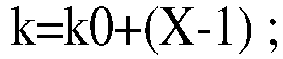

k0 étant une quantité de créneaux entre les DCI et un premier créneau dans lequel une transmission de liaison descendante programmée par les DCI est située, k1 étant une quantité de créneaux entre une fin de la transmission de liaison descendante et une rétroaction de liaison montante correspondant à la transmission de liaison descendante, X valant 1 ou étant une quantité de créneaux en agrégation de créneaux pendant la transmission de liaison descendante, et ΔDL étant une valeur configurée, ou ΔDL étant déterminée d'après un symbole occupé par un canal de la rétroaction de liaison montante, ou ΔDL étant une valeur déterminée d'après un créneau qui pourrait être utilisé pour émettre le SRS. - Procédé selon la revendication 1, tel que si l'UE (300, 500) reçoit les DCI dans un nième créneau, le créneau qui est déterminé par l'UE (300, 500) et dans lequel le SRS est émis est un (n+k)ème créneau, et
 k=k2,k2 étant une quantité d'intervalles de créneaux entre les DCI et une transmission de liaison montante programmée par les DCI, et ΔUL étant une valeur configurée, ou ΔUL étant une valeur déterminée d'après un symbole occupé par un canal de la transmission de liaison montante, ou ΔUL étant une valeur déterminée d'après un créneau servant à transmettre le SRS, ou ΔUL étant une valeur déterminée d'après une quantité de créneaux en agrégation de créneaux pendant la transmission de liaison montante.
 - Procédé selon la revendication 1, tel que si l'UE (300, 500) reçoit les DCI dans un nième créneau, le créneau qui est déterminé par l'UE (300, 500) et dans lequel le SRS est émis est un (n+k)ème créneau, etles DCI comportent un contenu utilisé pour indiquer une valeur de k ; ouk est une valeur préconfigurée.
- Procédé selon la revendication 4, le fait que les DCI comportent un contenu utilisé pour indiquer une valeur de k comportant le fait que :les DCI comportent un contenu utilisé pour indiquer que la valeur de k fait partie d'un ensemble candidat de valeurs de k, et l'ensemble candidat des valeurs de k est un des suivants : un ensemble candidat de valeurs de k0, un ensemble candidat de valeurs de k1, et un ensemble candidat de valeurs de k2,l'ensemble candidat des valeurs de k0 étant un ensemble candidat d'une quantité de créneaux entre les DCI et un premier créneau dans lequel une transmission de liaison descendante programmée par les DCI est située,l'ensemble candidat des valeurs de k1 étant un ensemble candidat d'une quantité de créneaux entre une fin de la transmission de liaison descendante programmée par les DCI et une rétroaction de liaison montante correspondant à la transmission de liaison descendante, etl'ensemble candidat des valeurs de k2 étant un ensemble candidat d'intervalles de créneaux entre les DCI et une transmission de liaison montante programmée par les DCI.
- Procédé selon l'une quelconque des revendications 1 à 5, les informations de configuration de ressources de SRS comportant des informations utilisées pour indiquer le symbole servant à transmettre le SRS, les informations utilisées pour indiquer le symbole servant à transmettre le SRS étant utilisées pour indiquer un contenu comportant l'emplacement d'un symbole S de début d'une ressource, dans un seul créneau, servant à transmettre le SRS, une quantité N de symboles de la ressource servant à transmettre le SRS, et un facteur r de répétition de la ressource servant à transmettre le SRS, et deux éléments quelconques parmi S, N et r étant codés conjointement, ou S, N, et r étant codés conjointement.
- Procédé de transmission de signal de référence de sondage, SRS, comportant :l'envoi, par une station (400, 600) de base, d'informations de configuration de ressources de SRS à un équipement d'utilisateur UE (300, 500) ;l'envoi, par la station (400, 600) de base, d'informations de commande de liaison descendante, DCI, à l'UE (300, 500) ; etla réception, par la station (400, 600) de base, d'un SRS en provenance de l'UE (300, 500) dans un créneau et un symbole déterminés, le symbole étant déterminé par l'UE d'après les informations de configuration de ressources de SRS,les informations de configuration de ressources de SRS comportant des informations de configuration utilisées pour indiquer un ensemble de ressources de SRS, l'ensemble de ressources de SRS comportant une ou plusieurs ressources de SRS, caractérisé en ce queles informations de configuration de ressources de SRS comportent en outre des informations utilisées pour indiquer que l'ensemble de ressources de SRS possède au moins deux fonctions parmi quatre : gestion de faisceau, interrogation d'antennes, transmission basée sur un répertoire de codes, et transmission non basée sur un répertoire de codes.
- Procédé selon la revendication 7, la station de base envoyant les DCI à l'UE dans un nième créneau et recevant le SRS dans un (n+k)ème créneau, et les DCI comportant un contenu utilisé pour indiquer une valeur de k ; oules DCI comportant un contenu utilisé pour indiquer que la valeur de k fait partie d'un ensemble candidat de valeurs de k, et l'ensemble candidat des valeurs de k étant un des suivants : un ensemble candidat de valeurs de k0, un ensemble candidat de valeurs de k1, et un ensemble candidat de valeurs de k2,l'ensemble candidat des valeurs de k0 étant un ensemble candidat d'une quantité de créneaux entre les DCI et un premier créneau dans lequel une transmission de liaison descendante programmée par les DCI est située,l'ensemble candidat des valeurs de k1 étant un ensemble candidat d'une quantité de créneaux entre une fin de la transmission de liaison descendante programmée par les DCI et une rétroaction de liaison montante correspondant à la transmission de liaison descendante, etl'ensemble candidat des valeurs de k2 étant un ensemble candidat d'intervalles de créneaux entre les DCI et une transmission de liaison montante programmée par les DCI.
- Procédé selon l'une quelconque des revendications 7 et 8, les informations de configuration de ressources de SRS comportant des informations utilisées pour indiquer un symbole servant à transmettre le SRS, les informations utilisées pour indiquer le symbole servant à transmettre le SRS étant utilisées pour indiquer un contenu comportant l'emplacement d'un symbole S de début d'une ressource, dans un seul créneau, servant à transmettre le SRS, une quantité N de symboles de la ressource servant à transmettre le SRS, et un facteur r de répétition de la ressource servant à transmettre le SRS, et deux éléments quelconques parmi S, N et r étant codés conjointement, ou S, N, et r étant codés conjointement.
- Appareil de communications qui, lorsqu'il est associé à un équipement (300, 500) d'utilisateur, comporte des moyens qui sont configurés pour réaliser le procédé selon l'une quelconque des revendications 1 à 6, ou qui,
lorsqu'il est associé à une station (400, 600) de base, comporte des moyens qui sont configurés pour réaliser le procédé selon l'une quelconque des revendications 7 à 9. - Support (502, 602) de stockage, le support (502, 602) de stockage conservant un programme d'ordinateur comportant des instructions, et lorsque le programme d'ordinateur est exécuté par un ordinateur (501) associé à un équipement (300, 500) d'utilisateur, les instructions amenant l'équipement (300, 500) d'utilisateur à réaliser le procédé selon l'une quelconque des revendications 1 à 6, ou
lorsque le programme d'ordinateur est exécuté par un ordinateur (601) associé à une station (400, 600) de base, les instructions amenant la station (400, 600) de base à réaliser le procédé selon l'une quelconque des revendications 7 à 9. - Système de puces, comportant un processeur (501) associé à un équipement (300, 500) d'utilisateur, le processeur (501) étant configuré pour exécuter des instructions qui amènent l'équipement (300, 500) d'utilisateur à réaliser le procédé selon l'une quelconque des revendications 1 à 6, ou
comportant un processeur (601) associé à une station (400, 600) de base, le processeur (601) étant configuré pour exécuter des instructions qui amènent la station (400, 600) de base à réaliser le procédé selon l'une quelconque des revendications 7 à 9. - Produit de programme d'ordinateur, comportant une instruction ou du code exécutables par ordinateur stockés sur un support lisible par ordinateur, tels que lorsque l'instruction ou le code sont exécutés par un processeur (501) associé à un équipement (300, 500) d'utilisateur, ils amènent l'équipement (300, 500) d'utilisateur à réaliser le procédé selon l'une quelconque des revendications 1 à 6, ou lorsque l'instruction ou le code sont exécutés par un processeur (601) associé à une station (400, 600) de base, ils amènent la station (400, 600) de base à réaliser le procédé selon l'une quelconque des revendications 7 à 9.
Applications Claiming Priority (2)
| Application Number | Priority Date | Filing Date | Title |
|---|---|---|---|
| CN201810032482.7A CN110034889B (zh) | 2018-01-12 | 2018-01-12 | 一种探测参考信号srs配置方法和装置 |
| PCT/CN2018/123784 WO2019137211A1 (fr) | 2018-01-12 | 2018-12-26 | Procédé de configuration et dispositif de signal de référence de sondage (srs) |
Publications (3)
| Publication Number | Publication Date |
|---|---|
| EP3720177A1 EP3720177A1 (fr) | 2020-10-07 |
| EP3720177A4 EP3720177A4 (fr) | 2021-01-20 |
| EP3720177B1 true EP3720177B1 (fr) | 2022-10-26 |
Family
ID=67218189
Family Applications (1)
| Application Number | Title | Priority Date | Filing Date |
|---|---|---|---|
| EP18899154.1A Active EP3720177B1 (fr) | 2018-01-12 | 2018-12-26 | Procédé de configuration et dispositif de signal de référence de sondage (srs) |
Country Status (4)
| Country | Link |
|---|---|
| US (1) | US11431528B2 (fr) |
| EP (1) | EP3720177B1 (fr) |
| CN (1) | CN110034889B (fr) |
| WO (1) | WO2019137211A1 (fr) |
Families Citing this family (28)
| Publication number | Priority date | Publication date | Assignee | Title |
|---|---|---|---|---|
| WO2020248158A1 (fr) * | 2019-06-12 | 2020-12-17 | Qualcomm Incorporated | Configuration adaptative de port de signal de référence de sondage |
| WO2021026675A1 (fr) * | 2019-08-09 | 2021-02-18 | Qualcomm Incorporated | Groupe de blocs de ressources de précodage de liaison montante pour précodage de liaison montante sélectif en fréquence non basé sur un livre de codes |
| CN110536450B (zh) * | 2019-09-03 | 2025-02-11 | 中兴通讯股份有限公司 | 一种数据传输方法、装置、传输接收节点、终端及介质 |
| CN111092708B (zh) * | 2019-11-08 | 2024-09-10 | 中兴通讯股份有限公司 | 传输方法、装置、第一通信节点、第二通信节点及介质 |
| CN111901079B (zh) * | 2020-01-03 | 2024-10-29 | 中兴通讯股份有限公司 | 参考信号发送、接收方法、装置、通信节点及介质 |
| CN113163488B (zh) * | 2020-01-22 | 2023-02-03 | 维沃移动通信有限公司 | 非周期srs资源集的触发方法及设备 |
| US11468328B2 (en) * | 2020-02-24 | 2022-10-11 | Qualcomm Incorporated | Managing information transmission for wireless communication |
| WO2021168599A1 (fr) * | 2020-02-24 | 2021-09-02 | Qualcomm Incorporated | Configurations de signal de référence pour sélection de faisceau de liaison montante |
| EP4085561B1 (fr) * | 2020-03-30 | 2025-10-22 | Guangdong Oppo Mobile Telecommunications Corp., Ltd. | Procédé et dispositif de communication |
| CN113498180B (zh) * | 2020-04-02 | 2024-08-30 | 维沃移动通信有限公司 | 无线通信方法、网络设备和终端设备 |
| CN115039475B (zh) * | 2020-04-11 | 2025-04-01 | 中兴通讯股份有限公司 | 一种用于改进的探测参考信号(srs)开销和灵活重用方案的方法和系统 |
| CN113810997B (zh) * | 2020-06-12 | 2024-11-19 | 维沃移动通信有限公司 | Srs资源指示方法、srs资源确定方法及相关设备 |
| US11700073B2 (en) * | 2020-07-10 | 2023-07-11 | Qualcomm Incorporated | Group common DCI for CLI measurement and reporting |
| CN114070501B (zh) * | 2020-07-31 | 2023-04-07 | 展讯通信(上海)有限公司 | 非周期探测参考信号的发送方法及设备 |
| CN112039646B (zh) * | 2020-08-11 | 2023-04-28 | 中国信息通信研究院 | 一种上行定位导频指示方法和装置 |
| CN114337946B (zh) * | 2020-09-29 | 2025-04-29 | 维沃移动通信有限公司 | 探测参考信号配置方法、终端及网络侧设备 |
| CN114501627B (zh) * | 2020-10-23 | 2025-09-16 | 大唐移动通信设备有限公司 | 信号传输方法、终端、网络设备、装置及存储介质 |
| WO2022099556A1 (fr) | 2020-11-12 | 2022-05-19 | Oppo广东移动通信有限公司 | Procédé et dispositif de communication sans fil |
| WO2022133706A1 (fr) * | 2020-12-22 | 2022-06-30 | Qualcomm Incorporated | Détermination dynamique de créneaux disponibles pour la transmission d'informations de signal de référence de sondage (srs) |
| EP4268408A4 (fr) | 2020-12-22 | 2024-11-20 | Qualcomm Incorporated | Détermination dynamique d'intervalles disponibles pour la transmission d'informations de signaux de référence de sondage (srs) |
| CN116615882B (zh) * | 2020-12-24 | 2024-06-21 | 高通股份有限公司 | 确定用于非周期性探通参考信号(srs)资源集的可用时隙 |
| CN115088349B (zh) * | 2021-01-11 | 2025-03-11 | 北京小米移动软件有限公司 | 一种传输方法、传输装置及存储介质 |
| US12349150B2 (en) * | 2021-01-17 | 2025-07-01 | Qualcomm Incorporated | Multiple sounding reference signal transmissions triggered by downlink control information |
| EP4335060A4 (fr) * | 2021-05-04 | 2025-01-08 | Qualcomm Incorporated | Périodes de garde pour ensembles de ressources de signal de référence de sondage |
| CN115334622B (zh) * | 2021-05-11 | 2024-09-27 | 展讯通信(上海)有限公司 | 多时间间隔数据传输方法及装置、用户设备 |
| US20250358797A1 (en) * | 2022-06-10 | 2025-11-20 | Beijing Xiaomi Mobile Software Co., Ltd. | Method and device for transmitting time domain resource configuration information and readable storage medium |
| WO2025190266A1 (fr) * | 2024-03-11 | 2025-09-18 | Mediatek Inc. | Réduction de surdébit de signal de référence par retour de décision de symbole de données en communication et détection conjointes à diversité spatiale |
| CN119853780B (zh) * | 2025-03-20 | 2025-05-16 | 中国电子科技集团公司第五十四研究所 | 一种高轨卫星通信系统中pusch信道发送控制方法及装置 |
Family Cites Families (12)
| Publication number | Priority date | Publication date | Assignee | Title |
|---|---|---|---|---|
| CN102165720B (zh) * | 2008-09-26 | 2015-10-14 | 三星电子株式会社 | 支持多个天线的探测参考信号发射的装置及方法 |
| KR101639810B1 (ko) * | 2009-01-13 | 2016-07-25 | 엘지전자 주식회사 | 무선통신 시스템에서 사운딩 참조신호의 전송방법 |
| CN101917765B (zh) * | 2010-08-13 | 2015-09-16 | 中兴通讯股份有限公司 | 一种测量参考信号的配置方法及系统 |
| CN102595514B (zh) * | 2011-01-12 | 2015-03-18 | 上海贝尔股份有限公司 | 非周期性探测参考信号的配置方法 |
| US20130294318A1 (en) * | 2012-05-03 | 2013-11-07 | Qualcomm Incorporated | Efficient update of tmgi list in lte embms |
| CN106233658B (zh) * | 2014-04-20 | 2019-07-16 | Lg电子株式会社 | 在无线通信系统中发送探测参考信号的方法和终端 |
| US11818717B2 (en) * | 2014-12-31 | 2023-11-14 | Texas Instruments Incorporated | Method and apparatus for uplink control signaling with massive Carrier Aggregation |
| CN111740812B (zh) * | 2016-04-01 | 2022-09-20 | 中兴通讯股份有限公司 | 探测参考信号发送方法 |
| US10367616B2 (en) * | 2016-04-04 | 2019-07-30 | Qualcomm Incorporated | Dynamic sounding reference signal scheduling |
| US20170331606A1 (en) * | 2016-05-13 | 2017-11-16 | Mediatek Inc. | Sounding Reference Signal Design for LAA |
| CN115767749A (zh) * | 2017-07-27 | 2023-03-07 | Lg电子株式会社 | 发送srs的方法及用户设备、接收srs的方法及基站 |
| US11050478B2 (en) * | 2017-12-19 | 2021-06-29 | Samsung Electronics Co., Ltd. | Method and apparatus for beam reporting in next generation wireless systems |
-
2018
- 2018-01-12 CN CN201810032482.7A patent/CN110034889B/zh active Active
- 2018-12-26 EP EP18899154.1A patent/EP3720177B1/fr active Active
- 2018-12-26 WO PCT/CN2018/123784 patent/WO2019137211A1/fr not_active Ceased
-
2020
- 2020-07-07 US US16/922,771 patent/US11431528B2/en active Active
Also Published As
| Publication number | Publication date |
|---|---|
| CN110034889B (zh) | 2021-12-28 |
| US20200336340A1 (en) | 2020-10-22 |
| EP3720177A4 (fr) | 2021-01-20 |
| WO2019137211A1 (fr) | 2019-07-18 |
| CN110034889A (zh) | 2019-07-19 |
| EP3720177A1 (fr) | 2020-10-07 |
| US11431528B2 (en) | 2022-08-30 |
Similar Documents
| Publication | Publication Date | Title |
|---|---|---|
| EP3720177B1 (fr) | Procédé de configuration et dispositif de signal de référence de sondage (srs) | |
| US11146370B2 (en) | Wireless communication method and wireless communications apparatus | |
| EP3713335B1 (fr) | Procédé et appareil d'envoi de signal de référence de sondage (srs) | |
| EP4024741B1 (fr) | Procédé et appareil de transmission de données de liaison montante | |
| EP3611979B1 (fr) | Procédé de détermination de paramètres de transmission d'un signal de liaison montante, terminal et dispositif de réseau | |
| US10951440B2 (en) | Method for uplink data transmission, terminal device and network device | |
| US11539483B2 (en) | Wireless communication method and apparatus | |
| EP3852464A1 (fr) | Procédé et dispositif de transmission de données | |
| US11006410B2 (en) | Method and apparatus for transmitting uplink information | |
| EP3627747B1 (fr) | Appareil et procédé de transmission d'informations | |
| US11463960B2 (en) | Uplink transmission method and terminal device | |
| CA3066296C (fr) | Procede de transmission de donnees et dispositif de terminal | |
| CN109314873B (zh) | 一种数据处理方法、终端以及基站 | |
| EP3506698B1 (fr) | Procédé de communication, terminal et dispositif réseau | |
| US10652902B2 (en) | Method for measuring channel state information, network-side device, and user equipment | |
| US11470635B2 (en) | Communication method and device | |
| EP3618298B1 (fr) | Procédé de transmission de signal de liaison descendante, dispositif terminal et dispositif de réseau | |
| EP3579630A1 (fr) | Procédé et dispositif de transmission d'informations de commande de liaison descendante | |
| US20210022166A1 (en) | Resource allocation method and apparatus |
Legal Events
| Date | Code | Title | Description |
|---|---|---|---|
| STAA | Information on the status of an ep patent application or granted ep patent |
Free format text: STATUS: THE INTERNATIONAL PUBLICATION HAS BEEN MADE |
|
| PUAI | Public reference made under article 153(3) epc to a published international application that has entered the european phase |
Free format text: ORIGINAL CODE: 0009012 |
|
| STAA | Information on the status of an ep patent application or granted ep patent |
Free format text: STATUS: REQUEST FOR EXAMINATION WAS MADE |
|
| 17P | Request for examination filed |
Effective date: 20200701 |
|
| AK | Designated contracting states |
Kind code of ref document: A1 Designated state(s): AL AT BE BG CH CY CZ DE DK EE ES FI FR GB GR HR HU IE IS IT LI LT LU LV MC MK MT NL NO PL PT RO RS SE SI SK SM TR |
|
| AX | Request for extension of the european patent |
Extension state: BA ME |
|
| A4 | Supplementary search report drawn up and despatched |
Effective date: 20201217 |
|
| RIC1 | Information provided on ipc code assigned before grant |
Ipc: H04L 5/00 20060101AFI20201211BHEP |
|
| DAV | Request for validation of the european patent (deleted) | ||
| DAX | Request for extension of the european patent (deleted) | ||
| RIC1 | Information provided on ipc code assigned before grant |
Ipc: H04B 7/06 20060101ALN20220407BHEP Ipc: H04B 7/0408 20170101ALI20220407BHEP Ipc: H04L 5/00 20060101AFI20220407BHEP |
|
| REG | Reference to a national code |
Ref country code: DE Ref legal event code: R079 Ref document number: 602018042425 Country of ref document: DE Free format text: PREVIOUS MAIN CLASS: H04W0028160000 Ipc: H04L0005000000 |
|
| RIC1 | Information provided on ipc code assigned before grant |
Ipc: H04B 7/06 20060101ALN20220419BHEP Ipc: H04B 7/0408 20170101ALI20220419BHEP Ipc: H04L 5/00 20060101AFI20220419BHEP |
|
| GRAP | Despatch of communication of intention to grant a patent |
Free format text: ORIGINAL CODE: EPIDOSNIGR1 |
|
| STAA | Information on the status of an ep patent application or granted ep patent |
Free format text: STATUS: GRANT OF PATENT IS INTENDED |
|
| RIC1 | Information provided on ipc code assigned before grant |
Ipc: H04B 7/06 20060101ALN20220519BHEP Ipc: H04B 7/0408 20170101ALI20220519BHEP Ipc: H04L 5/00 20060101AFI20220519BHEP |
|
| INTG | Intention to grant announced |
Effective date: 20220601 |
|
| GRAS | Grant fee paid |
Free format text: ORIGINAL CODE: EPIDOSNIGR3 |
|
| GRAA | (expected) grant |
Free format text: ORIGINAL CODE: 0009210 |
|
| STAA | Information on the status of an ep patent application or granted ep patent |
Free format text: STATUS: THE PATENT HAS BEEN GRANTED |
|
| AK | Designated contracting states |
Kind code of ref document: B1 Designated state(s): AL AT BE BG CH CY CZ DE DK EE ES FI FR GB GR HR HU IE IS IT LI LT LU LV MC MK MT NL NO PL PT RO RS SE SI SK SM TR |
|
| REG | Reference to a national code |
Ref country code: GB Ref legal event code: FG4D |
|
| REG | Reference to a national code |
Ref country code: CH Ref legal event code: EP |
|
| REG | Reference to a national code |
Ref country code: DE Ref legal event code: R096 Ref document number: 602018042425 Country of ref document: DE |
|
| REG | Reference to a national code |
Ref country code: AT Ref legal event code: REF Ref document number: 1527867 Country of ref document: AT Kind code of ref document: T Effective date: 20221115 |
|
| REG | Reference to a national code |
Ref country code: IE Ref legal event code: FG4D |
|
| REG | Reference to a national code |
Ref country code: LT Ref legal event code: MG9D |
|
| REG | Reference to a national code |
Ref country code: NL Ref legal event code: MP Effective date: 20221026 |
|
| REG | Reference to a national code |
Ref country code: AT Ref legal event code: MK05 Ref document number: 1527867 Country of ref document: AT Kind code of ref document: T Effective date: 20221026 |
|
| PG25 | Lapsed in a contracting state [announced via postgrant information from national office to epo] |
Ref country code: NL Free format text: LAPSE BECAUSE OF FAILURE TO SUBMIT A TRANSLATION OF THE DESCRIPTION OR TO PAY THE FEE WITHIN THE PRESCRIBED TIME-LIMIT Effective date: 20221026 |
|
| PG25 | Lapsed in a contracting state [announced via postgrant information from national office to epo] |
Ref country code: SE Free format text: LAPSE BECAUSE OF FAILURE TO SUBMIT A TRANSLATION OF THE DESCRIPTION OR TO PAY THE FEE WITHIN THE PRESCRIBED TIME-LIMIT Effective date: 20221026 Ref country code: PT Free format text: LAPSE BECAUSE OF FAILURE TO SUBMIT A TRANSLATION OF THE DESCRIPTION OR TO PAY THE FEE WITHIN THE PRESCRIBED TIME-LIMIT Effective date: 20230227 Ref country code: NO Free format text: LAPSE BECAUSE OF FAILURE TO SUBMIT A TRANSLATION OF THE DESCRIPTION OR TO PAY THE FEE WITHIN THE PRESCRIBED TIME-LIMIT Effective date: 20230126 Ref country code: LT Free format text: LAPSE BECAUSE OF FAILURE TO SUBMIT A TRANSLATION OF THE DESCRIPTION OR TO PAY THE FEE WITHIN THE PRESCRIBED TIME-LIMIT Effective date: 20221026 Ref country code: FI Free format text: LAPSE BECAUSE OF FAILURE TO SUBMIT A TRANSLATION OF THE DESCRIPTION OR TO PAY THE FEE WITHIN THE PRESCRIBED TIME-LIMIT Effective date: 20221026 Ref country code: ES Free format text: LAPSE BECAUSE OF FAILURE TO SUBMIT A TRANSLATION OF THE DESCRIPTION OR TO PAY THE FEE WITHIN THE PRESCRIBED TIME-LIMIT Effective date: 20221026 Ref country code: AT Free format text: LAPSE BECAUSE OF FAILURE TO SUBMIT A TRANSLATION OF THE DESCRIPTION OR TO PAY THE FEE WITHIN THE PRESCRIBED TIME-LIMIT Effective date: 20221026 |
|
| PG25 | Lapsed in a contracting state [announced via postgrant information from national office to epo] |
Ref country code: RS Free format text: LAPSE BECAUSE OF FAILURE TO SUBMIT A TRANSLATION OF THE DESCRIPTION OR TO PAY THE FEE WITHIN THE PRESCRIBED TIME-LIMIT Effective date: 20221026 Ref country code: PL Free format text: LAPSE BECAUSE OF FAILURE TO SUBMIT A TRANSLATION OF THE DESCRIPTION OR TO PAY THE FEE WITHIN THE PRESCRIBED TIME-LIMIT Effective date: 20221026 Ref country code: LV Free format text: LAPSE BECAUSE OF FAILURE TO SUBMIT A TRANSLATION OF THE DESCRIPTION OR TO PAY THE FEE WITHIN THE PRESCRIBED TIME-LIMIT Effective date: 20221026 Ref country code: IS Free format text: LAPSE BECAUSE OF FAILURE TO SUBMIT A TRANSLATION OF THE DESCRIPTION OR TO PAY THE FEE WITHIN THE PRESCRIBED TIME-LIMIT Effective date: 20230226 Ref country code: HR Free format text: LAPSE BECAUSE OF FAILURE TO SUBMIT A TRANSLATION OF THE DESCRIPTION OR TO PAY THE FEE WITHIN THE PRESCRIBED TIME-LIMIT Effective date: 20221026 Ref country code: GR Free format text: LAPSE BECAUSE OF FAILURE TO SUBMIT A TRANSLATION OF THE DESCRIPTION OR TO PAY THE FEE WITHIN THE PRESCRIBED TIME-LIMIT Effective date: 20230127 |
|
| REG | Reference to a national code |
Ref country code: DE Ref legal event code: R119 Ref document number: 602018042425 Country of ref document: DE |
|
| PG25 | Lapsed in a contracting state [announced via postgrant information from national office to epo] |
Ref country code: SM Free format text: LAPSE BECAUSE OF FAILURE TO SUBMIT A TRANSLATION OF THE DESCRIPTION OR TO PAY THE FEE WITHIN THE PRESCRIBED TIME-LIMIT Effective date: 20221026 Ref country code: RO Free format text: LAPSE BECAUSE OF FAILURE TO SUBMIT A TRANSLATION OF THE DESCRIPTION OR TO PAY THE FEE WITHIN THE PRESCRIBED TIME-LIMIT Effective date: 20221026 Ref country code: EE Free format text: LAPSE BECAUSE OF FAILURE TO SUBMIT A TRANSLATION OF THE DESCRIPTION OR TO PAY THE FEE WITHIN THE PRESCRIBED TIME-LIMIT Effective date: 20221026 Ref country code: DK Free format text: LAPSE BECAUSE OF FAILURE TO SUBMIT A TRANSLATION OF THE DESCRIPTION OR TO PAY THE FEE WITHIN THE PRESCRIBED TIME-LIMIT Effective date: 20221026 Ref country code: CZ Free format text: LAPSE BECAUSE OF FAILURE TO SUBMIT A TRANSLATION OF THE DESCRIPTION OR TO PAY THE FEE WITHIN THE PRESCRIBED TIME-LIMIT Effective date: 20221026 |
|
| REG | Reference to a national code |
Ref country code: CH Ref legal event code: PL |
|
| REG | Reference to a national code |
Ref country code: BE Ref legal event code: MM Effective date: 20221231 |
|
| PG25 | Lapsed in a contracting state [announced via postgrant information from national office to epo] |
Ref country code: SK Free format text: LAPSE BECAUSE OF FAILURE TO SUBMIT A TRANSLATION OF THE DESCRIPTION OR TO PAY THE FEE WITHIN THE PRESCRIBED TIME-LIMIT Effective date: 20221026 Ref country code: LU Free format text: LAPSE BECAUSE OF NON-PAYMENT OF DUE FEES Effective date: 20221226 Ref country code: AL Free format text: LAPSE BECAUSE OF FAILURE TO SUBMIT A TRANSLATION OF THE DESCRIPTION OR TO PAY THE FEE WITHIN THE PRESCRIBED TIME-LIMIT Effective date: 20221026 |
|
| PLBE | No opposition filed within time limit |
Free format text: ORIGINAL CODE: 0009261 |
|
| STAA | Information on the status of an ep patent application or granted ep patent |
Free format text: STATUS: NO OPPOSITION FILED WITHIN TIME LIMIT |
|
| 26N | No opposition filed |
Effective date: 20230727 |
|
| PG25 | Lapsed in a contracting state [announced via postgrant information from national office to epo] |
Ref country code: LI Free format text: LAPSE BECAUSE OF NON-PAYMENT OF DUE FEES Effective date: 20221231 Ref country code: IE Free format text: LAPSE BECAUSE OF NON-PAYMENT OF DUE FEES Effective date: 20221226 Ref country code: DE Free format text: LAPSE BECAUSE OF NON-PAYMENT OF DUE FEES Effective date: 20230701 Ref country code: CH Free format text: LAPSE BECAUSE OF NON-PAYMENT OF DUE FEES Effective date: 20221231 |
|
| PG25 | Lapsed in a contracting state [announced via postgrant information from national office to epo] |
Ref country code: SI Free format text: LAPSE BECAUSE OF FAILURE TO SUBMIT A TRANSLATION OF THE DESCRIPTION OR TO PAY THE FEE WITHIN THE PRESCRIBED TIME-LIMIT Effective date: 20221026 Ref country code: FR Free format text: LAPSE BECAUSE OF NON-PAYMENT OF DUE FEES Effective date: 20221226 Ref country code: BE Free format text: LAPSE BECAUSE OF NON-PAYMENT OF DUE FEES Effective date: 20221231 |
|
| PG25 | Lapsed in a contracting state [announced via postgrant information from national office to epo] |
Ref country code: CY Free format text: LAPSE BECAUSE OF FAILURE TO SUBMIT A TRANSLATION OF THE DESCRIPTION OR TO PAY THE FEE WITHIN THE PRESCRIBED TIME-LIMIT Effective date: 20221026 |
|
| PG25 | Lapsed in a contracting state [announced via postgrant information from national office to epo] |
Ref country code: MK Free format text: LAPSE BECAUSE OF FAILURE TO SUBMIT A TRANSLATION OF THE DESCRIPTION OR TO PAY THE FEE WITHIN THE PRESCRIBED TIME-LIMIT Effective date: 20221026 Ref country code: IT Free format text: LAPSE BECAUSE OF FAILURE TO SUBMIT A TRANSLATION OF THE DESCRIPTION OR TO PAY THE FEE WITHIN THE PRESCRIBED TIME-LIMIT Effective date: 20221026 Ref country code: HU Free format text: LAPSE BECAUSE OF FAILURE TO SUBMIT A TRANSLATION OF THE DESCRIPTION OR TO PAY THE FEE WITHIN THE PRESCRIBED TIME-LIMIT; INVALID AB INITIO Effective date: 20181226 |
|
| PG25 | Lapsed in a contracting state [announced via postgrant information from national office to epo] |
Ref country code: MC Free format text: LAPSE BECAUSE OF FAILURE TO SUBMIT A TRANSLATION OF THE DESCRIPTION OR TO PAY THE FEE WITHIN THE PRESCRIBED TIME-LIMIT Effective date: 20221026 |
|
| PG25 | Lapsed in a contracting state [announced via postgrant information from national office to epo] |
Ref country code: MC Free format text: LAPSE BECAUSE OF FAILURE TO SUBMIT A TRANSLATION OF THE DESCRIPTION OR TO PAY THE FEE WITHIN THE PRESCRIBED TIME-LIMIT Effective date: 20221026 |
|
| PG25 | Lapsed in a contracting state [announced via postgrant information from national office to epo] |
Ref country code: BG Free format text: LAPSE BECAUSE OF FAILURE TO SUBMIT A TRANSLATION OF THE DESCRIPTION OR TO PAY THE FEE WITHIN THE PRESCRIBED TIME-LIMIT Effective date: 20221026 |
|
| PG25 | Lapsed in a contracting state [announced via postgrant information from national office to epo] |
Ref country code: MT Free format text: LAPSE BECAUSE OF FAILURE TO SUBMIT A TRANSLATION OF THE DESCRIPTION OR TO PAY THE FEE WITHIN THE PRESCRIBED TIME-LIMIT Effective date: 20221026 |
|
| PG25 | Lapsed in a contracting state [announced via postgrant information from national office to epo] |
Ref country code: TR Free format text: LAPSE BECAUSE OF FAILURE TO SUBMIT A TRANSLATION OF THE DESCRIPTION OR TO PAY THE FEE WITHIN THE PRESCRIBED TIME-LIMIT Effective date: 20221026 |
|
| PGFP | Annual fee paid to national office [announced via postgrant information from national office to epo] |
Ref country code: GB Payment date: 20251114 Year of fee payment: 8 |