EP3720183A1 - Procédé de transmission de données, appareil de communication et entité fonctionnelle de plan d'utilisateur - Google Patents
Procédé de transmission de données, appareil de communication et entité fonctionnelle de plan d'utilisateur Download PDFInfo
- Publication number
- EP3720183A1 EP3720183A1 EP19747478.6A EP19747478A EP3720183A1 EP 3720183 A1 EP3720183 A1 EP 3720183A1 EP 19747478 A EP19747478 A EP 19747478A EP 3720183 A1 EP3720183 A1 EP 3720183A1
- Authority
- EP
- European Patent Office
- Prior art keywords
- function entity
- base station
- correspondence
- service flow
- communications apparatus
- Prior art date
- Legal status (The legal status is an assumption and is not a legal conclusion. Google has not performed a legal analysis and makes no representation as to the accuracy of the status listed.)
- Granted
Links
Images



Classifications
-
- H—ELECTRICITY
- H04—ELECTRIC COMMUNICATION TECHNIQUE
- H04L—TRANSMISSION OF DIGITAL INFORMATION, e.g. TELEGRAPHIC COMMUNICATION
- H04L43/00—Arrangements for monitoring or testing data switching networks
- H04L43/02—Capturing of monitoring data
- H04L43/026—Capturing of monitoring data using flow identification
-
- H—ELECTRICITY
- H04—ELECTRIC COMMUNICATION TECHNIQUE
- H04L—TRANSMISSION OF DIGITAL INFORMATION, e.g. TELEGRAPHIC COMMUNICATION
- H04L47/00—Traffic control in data switching networks
- H04L47/10—Flow control; Congestion control
- H04L47/24—Traffic characterised by specific attributes, e.g. priority or QoS
-
- H—ELECTRICITY
- H04—ELECTRIC COMMUNICATION TECHNIQUE
- H04L—TRANSMISSION OF DIGITAL INFORMATION, e.g. TELEGRAPHIC COMMUNICATION
- H04L47/00—Traffic control in data switching networks
- H04L47/50—Queue scheduling
- H04L47/56—Queue scheduling implementing delay-aware scheduling
-
- H—ELECTRICITY
- H04—ELECTRIC COMMUNICATION TECHNIQUE
- H04L—TRANSMISSION OF DIGITAL INFORMATION, e.g. TELEGRAPHIC COMMUNICATION
- H04L47/00—Traffic control in data switching networks
- H04L47/50—Queue scheduling
- H04L47/62—Queue scheduling characterised by scheduling criteria
- H04L47/6215—Individual queue per QOS, rate or priority
-
- H—ELECTRICITY
- H04—ELECTRIC COMMUNICATION TECHNIQUE
- H04L—TRANSMISSION OF DIGITAL INFORMATION, e.g. TELEGRAPHIC COMMUNICATION
- H04L67/00—Network arrangements or protocols for supporting network services or applications
- H04L67/14—Session management
-
- H—ELECTRICITY
- H04—ELECTRIC COMMUNICATION TECHNIQUE
- H04L—TRANSMISSION OF DIGITAL INFORMATION, e.g. TELEGRAPHIC COMMUNICATION
- H04L67/00—Network arrangements or protocols for supporting network services or applications
- H04L67/34—Network arrangements or protocols for supporting network services or applications involving the movement of software or configuration parameters
-
- H—ELECTRICITY
- H04—ELECTRIC COMMUNICATION TECHNIQUE
- H04W—WIRELESS COMMUNICATION NETWORKS
- H04W28/00—Network traffic management; Network resource management
- H04W28/02—Traffic management, e.g. flow control or congestion control
- H04W28/10—Flow control between communication endpoints
- H04W28/12—Flow control between communication endpoints using signalling between network elements
-
- H—ELECTRICITY
- H04—ELECTRIC COMMUNICATION TECHNIQUE
- H04W—WIRELESS COMMUNICATION NETWORKS
- H04W36/00—Hand-off or reselection arrangements
- H04W36/08—Reselecting an access point
-
- H—ELECTRICITY
- H04—ELECTRIC COMMUNICATION TECHNIQUE
- H04W—WIRELESS COMMUNICATION NETWORKS
- H04W36/00—Hand-off or reselection arrangements
- H04W36/0005—Control or signalling for completing the hand-off
- H04W36/0011—Control or signalling for completing the hand-off for data sessions of end-to-end connection
-
- H—ELECTRICITY
- H04—ELECTRIC COMMUNICATION TECHNIQUE
- H04W—WIRELESS COMMUNICATION NETWORKS
- H04W88/00—Devices specially adapted for wireless communication networks, e.g. terminals, base stations or access point devices
- H04W88/08—Access point devices
-
- H—ELECTRICITY
- H04—ELECTRIC COMMUNICATION TECHNIQUE
- H04W—WIRELESS COMMUNICATION NETWORKS
- H04W88/00—Devices specially adapted for wireless communication networks, e.g. terminals, base stations or access point devices
- H04W88/18—Service support devices; Network management devices
Definitions
- the present invention relates to the field of communications technologies, and in particular, to a data transmission method, a communications apparatus, and a user plane function entity.
- a jitter (jitter) requirement is also added to communication requirements, to describe an end-to-end latency change.
- Jitter indicates a fluctuation magnitude, with a specified range, of a period during which a message is transmitted from a transmit end to a receive end.
- some instructions need to periodically arrive at the receive end. Therefore, when a data packet including such instructions is periodically sent, a difference between periods during which data packets are transmitted from the transmit end to the receive end is required to be relatively small. The difference between periods even reaches millisecond-level jitter.
- an end-to-end latency of the data packet includes a processing latency at a node, a queuing latency of the data packet, a sending latency of a transmitter at the node, and a transmission latency on a link between the node and a receive end.
- the processing latency, sending latency, and transmission latency are relatively fixed.
- a technical problem to be resolved in embodiments of this application is to provide a data transmission method, a user plane function entity, and a base station, to resolve a problem that an existing end-to-end latency fluctuates greatly and jitter cannot be ensured.
- an embodiment of this application provides a data transmission method.
- the method includes:
- a communications apparatus obtains a correspondence between a quality of service flow identifier of a service flow and an inter-packet time interval of the service flow.
- the communications apparatus may establish, based on the correspondence, a gate queue used to send a data packet, and establish a mapping relationship between the gate queue and the quality of service flow identifier.
- the communications apparatus may detect the data packet and determine whether the data packet includes the quality of service flow identifier; and if the data packet includes the quality of service flow identifier, the communications apparatus may determine, based on the quality of service flow identifier, the gate queue to which the identifier is mapped, and then periodically schedule the data packet by using the gate queue to which the identifier is mapped.
- the communications apparatus may select, based on the QFI, the corresponding gate queue to periodically schedule and send the data packet, to implement a deterministic queuing latency, obtain ideal jitter parameter data, and ensure stability and reliability of data transmission.
- the communications apparatus may be a user plane function entity
- the upper-level sending device may be a base station
- the transmitted data packet is an uplink data packet
- a communications apparatus obtains a correspondence between a quality of service flow identifier of a service flow and an inter-packet time interval of the service flow includes: the communications apparatus receives the correspondence from a session management function entity.
- the UPF establishes an uplink gate queue to shape the uplink data packet sent by the base station and periodically schedule and send the uplink data packet, to ensure that the uplink data packet periodically and accurately arrives at a receive end device.
- the communications apparatus may be a base station
- the upper-level sending device may be a user plane function entity
- the transmitted data packet may be a downlink data packet.
- the base station establishes a downlink gate queue to shape the downlink data packet forwarded by the UPF and periodically schedule and send the downlink data packet, to ensure that the downlink data packet periodically and accurately arrives at a receive end device.
- a communications apparatus obtains a correspondence between a quality of service flow identifier of a service flow and an inter-packet time interval of the service flow includes:
- the source base station may receive the correspondence from an access and mobility management function entity; and then the source base station sends the correspondence to a target base station.
- the source base station may send the correspondence to the target base station, so that the target base station may establish the corresponding downlink gate queue to ensure periodic scheduling and sending of the downlink data packet.
- a communications apparatus obtains a correspondence between a quality of service flow identifier of a service flow and an inter-packet time interval of the service flow includes: The target base station receives the correspondence from a source base station.
- an embodiment of this application provides a data transmission method.
- the method includes:
- a session management function entity first obtains subscription information of a terminal device from a unified data management entity, where the subscription information includes an inter-packet time interval of a service flow.
- the session management function entity may allocate a quality of service flow identifier to the service flow, and establish a correspondence between the quality of service flow identifier and the inter-packet time interval.
- the session management function entity may send the correspondence to a communications apparatus, where the correspondence is used to periodically schedule a data packet.
- the communications apparatus may be a base station; and when the session management function entity sends the correspondence to the communications apparatus, if the communications apparatus is the base station, the session management function entity may send the correspondence to the base station through an access and mobility management function entity.
- the communications apparatus may be a user plane function entity.
- the user plane function entity may be a target user plane function entity, and before the session management function entity sends the correspondence to the communications apparatus, the method further includes:
- an embodiment of this application provides a communications apparatus.
- the apparatus includes:
- the communications apparatus is a user plane function entity
- the upper-level sending device is a base station
- the data packet is an uplink data packet
- the transceiver unit is specifically configured to receive the correspondence from a session management function entity.
- the communications apparatus is a base station
- the upper-level sending device is a user plane function entity
- the data packet is a downlink data packet.
- the transceiver unit is specifically configured to receive the correspondence from an access and mobility management function entity; and the transceiver unit is further configured to send the correspondence to a target base station.
- the transceiver unit is specifically configured to receive the correspondence from a source base station.
- an embodiment of this application provides a session management function entity.
- the session management function entity includes:
- the communications apparatus is a base station; and the transceiver unit is specifically configured to send the correspondence to the base station through an access and mobility management function entity.
- the communications apparatus is a user plane function entity.
- the user plane function entity is a target user plane function entity
- the transceiver unit before the transceiver unit sends the correspondence to the communications apparatus, the transceiver unit is further configured to receive, from an access and mobility management function entity, a request for reselecting a user plane function entity; and the processing unit is further configured to select the target user plane function entity; and the transceiver unit is further configured to send the correspondence to the target user plane function entity.
- an embodiment of this application provides a data transmission system.
- the system includes:
- an embodiment of this application provides a communications apparatus.
- the apparatus includes: a processor, a memory, an interface circuit, and a bus, where the processor, the memory, and the interface circuit are connected and communicate with each other by using the bus; the memory is configured to store a set of program code; and the processor is configured to invoke the program code stored in the memory, to perform the steps according to any one of the first aspect or the implementations of the first aspect in the embodiments of this application.
- an embodiment of this application provides a session management function entity.
- the session management function entity includes: a processor, a memory, an interface circuit, and a bus, where the processor, the memory, and the interface circuit are connected and communicate with each other by using the bus; the memory is configured to store a set of program code; and the processor is configured to invoke the program code stored in the memory, to perform the steps according to any one of the second aspect or the implementations of the second aspect in the embodiments of this application.
- an embodiment of this application provides a computer-readable storage medium.
- the computer-readable storage medium stores an instruction; and when the instruction is run on a computer, the computer is enabled to perform the method according to any one of the first aspect or the implementations of the first aspect in the embodiments of this application.
- an embodiment of this application provides a computer-readable storage medium.
- the computer-readable storage medium stores an instruction; and when the instruction is run on a computer, the computer is enabled to perform the method according to any one of the second aspect or the implementations of the second aspect in the embodiments of this application.
- FIG. 1 is a schematic diagram of a system architecture to which a data transmission method according to an embodiment of this application is applied.
- the system architecture is a typical system structure in a 5th generation mobile communications technology (5th Generation, 5G).
- 5G 5th Generation
- reference points of N1 to N27 ( FIG. 1 shows the reference points of N1 to N11) are defined, and the following network element function entities are defined.
- An access and mobility management function (Access and Mobility Management Function, AMF) 40 is configured for access and mobility management of UE.
- a data network (Data Network, DN) 80 includes, for example, an operator service, an internet access service, and a third-party service.
- a policy control function (Policy Control function, PCF) 70 is configured to formulate a QoS policy of a service.
- a session management function (Session Management Function, SMF) 50 is configured for session establishment, deletion, modification, and the like.
- Unified data management (Unified Data Management, UDM) 60 is configured to store subscription data of user equipment and the like.
- a user plane function (User plane Function, UPF) 30 is configured to forward a data packet.
- User Equipment 10 may also be referred to as a terminal or a terminal device, and is a device that provides a user with voice and/or data connectivity, for example, a handheld device hiving a wireless connection function, or another processing device connected to a wireless modem decoder.
- a (radio) access network ((Radio) Access Network, (R)AN) 20 is configured to enable a terminal to access a wireless network.
- the access network device includes but is not limited to an evolved NodeB (evolved NodeB, eNB), a radio network controller (radio network controller, RNC), a NodeB (NodeB, NB), a base station controller (Base Station Controller, BSC), a base transceiver station (Base Transceiver Station, BTS), a home base station (for example, a home evolved NodeB or a home NodeB, HNB), a baseband unit (BaseBand Unit, BBU), a Wi-Fi access point (Access Point, AP), or the like.
- the foregoing devices are collectively referred to as a base station 20 in this application.
- the base station 20 may provide a network signal for the terminal, and is responsible for sending downlink data to the terminal or sending uplink data of the terminal.
- Function entities mainly involved in the embodiments of this application include the UE 10, the (R)AN 20, the UPF 30, the AMF 40, the SMF 50, and the UDM 60.
- Function entities involved in data packet forwarding include the UPF 30 and the base station, that is, the (R)AN 20.
- a queuing latency of a data packet is not deterministic, and consequently an end-to-end latency fluctuates greatly.
- corresponding gate queues are established on the UPF 30 and the (R)AN 20, to periodically schedule transmitted data packets, so as to ensure determinism of the end-to-end latency and obtain ideal jitter parameter data.
- FIG. 2 is a schematic flowchart of a data transmission method according to an embodiment of this application. The method may be applied to a process of establishing a packet data unit (Packet Data Unit, PDU) session, and specifically includes the following steps.
- PDU Packet Data Unit
- a session management function entity obtains subscription information of a terminal device from a unified data management entity, where the subscription information includes an inter-packet time interval of a service flow.
- the session management function network element may be the SMF 50 in FIG. 1 .
- the unified data management entity may be the UDM 60 in FIG. 1 .
- the SMF 50 requests subscription information from the UDM 60, and obtains an inter-packet interval of a service flow from the subscription information returned by the UDM 60.
- the inter-packet time interval is a period during which a transmit end device periodically sends a data packet to a next-level receiving device of a transmission link.
- a UPF 30 may be the transmit end device, and the next-level receiving device may be a next-hop forwarding device of the transmission link, such as a switch or a router.
- the inter-packet time interval is a time interval at which the UPF 30 sends an uplink data packet to the next-hop forwarding device.
- a base station 20 may be the transmit end device, and the next-level receiving device may be UE 10.
- the inter-packet time interval is a time interval at which the base station 20 sends a downlink data packet to the UE 10.
- An uplink service flow and a downlink service flow are independent of each other. Therefore, an inter-packet time interval of an uplink data packet and an inter-packet time interval of a downlink data packet are also independent of each other.
- the inter-packet time interval may be accurate to a microsecond ( ⁇ s) level, in other words, the inter-packet time interval is measured in microseconds.
- S202 The session management function entity allocates a quality of service flow identifier (QoS flow identifier, QFI) to the service flow, and establishes a correspondence between the quality of service flow identifier and the inter-packet time interval.
- QoS flow identifier QoS flow identifier
- the QFI may be used as an identifier of a data packet related to the service flow.
- the SMF 50 may allocate a QFI to the service flow.
- the UPF 30 or the base station 20 may obtain the QFI and encapsulate the QFI into the data packet related to the service flow.
- a correspondence between the QFI and the inter-packet time interval is generated by the SMF 50.
- the session management function entity sends, to a communications apparatus, the correspondence between the quality of service flow identifier (QFI) of the service flow and the inter-packet time interval of the service flow.
- the communications apparatus obtains the correspondence between the quality of service flow identifier (QFI) of the service flow and the inter-packet time interval of the service flow.
- the communications apparatus establishes, based on the correspondence, a gate queue used to send a data packet, and establishes a mapping relationship between the gate queue and the quality of service flow identifier.
- S205 An upper-level sending device of a transmission link sends a data packet to the communications apparatus.
- the communications apparatus periodically schedules the data packet based on the gate queue to which the quality of service flow identifier is mapped.
- the gate queue is used to shape and periodically send the data packet.
- communications apparatuses are different, and manners of obtaining the correspondence between the QFI and the inter-packet time interval by the communications apparatuses are also different.
- the UPF 30 is used as a last-hop transmit end device of an uplink data packet in a mobile access network, and an uplink gate queue may be established on the UPF 30.
- the communications apparatus may be the UPF 30.
- the uplink gate queue may be used to periodically open and close a gate. A periodicity from opening to closing the gate may be determined based on an inter-packet time interval. In this way, when the gate is opened, the uplink data packet in the uplink gate queue can be sent; when the gate is closed, the uplink data packet cannot be sent.
- An uplink data packet queue is shaped through periodic opening and closing of the gate, to implement a deterministic queuing latency.
- the base station 20 is used as a last-hop transmit end device of a downlink data packet in a mobile access network, and a downlink gate queue may be established on the base station 20.
- the communications apparatus may be the base station 20.
- a downlink gate queue may be used to periodically open and close a gate. A periodicity from opening to closing the gate may be determined based on an inter-packet time interval. In this way, when the gate is opened, the downlink data packet can be sent; when the gate is closed, the downlink data packet cannot be sent.
- a downlink data packet queue is shaped through periodic opening and closing of the gate, to implement a deterministic queuing latency.
- the source base station may send the correspondence to a target base station when handover to the target base station is performed. Therefore, the target base station can complete establishment of a downlink gate queue and mapping between the downlink gate queue and the QFI.
- the communications apparatus may be the target base station. In this way, after the base station handover is completed, when receiving a downlink data packet including the QFI, the target base station can also periodically schedule and send the downlink data packet.
- the SMF 50 may reselect a UPF 30, and the SMF 50 sends the correspondence between the QFI and the inter-packet time interval to the target UPF, and therefore the target UPF can complete establishment of an uplink gate queue and mapping between the uplink gate queue and the QFI.
- the communications apparatus may be the target UPF.
- the data transmission method in this embodiment of this application is not only applicable to a mobile network, but also applicable to another application scenario in which a closed loop (closed loop) message needs to be transmitted and it needs to be ensured that the message periodically arrives at a receive end.
- the gate queue for shaping the data packet may be configured at a last-hop sending node of data transmission based on the inter-packet time interval, and the gate is periodically opened and closed to ensure the deterministic queuing latency; and a measurement unit at a corresponding level is used to implement accurate jitter parameter data.
- an SMF 50 receives the PDU session establishment request sent by the AMF 40, and sends a subscription information request to a UDM 60.
- the SMF 50 receives a subscription information response returned by the UDM 60, where the subscription information response includes an inter-packet time interval of a service flow; and then the SMF 50 allocates a quality of service flow identifier (QFI) to the service flow, and establishes a correspondence between the QFI and the inter-packet time interval.
- QFI quality of service flow identifier
- the SMF 50 may send a session establishment request or a session modification request to a UPF 30, where the session establishment request or the session modification request carries the correspondence between the QFI and the inter-packet time interval, so that the UPF 30 establishes an uplink gate queue based on the correspondence between the QFI and the inter-packet time interval and establishes a mapping relationship between the uplink gate queue and the QFI.
- the SMF 50 may alternatively send a PDU session establishment response to the AMF 40, where the PDU session establishment response carries the correspondence between the QFI and the inter-packet time interval, so that the AMF 40 sends, to a base station 20, a PDU session establishment request carrying the correspondence between the QFI and the inter-packet time interval, and the base station 20 establishes a downlink gate queue based on the correspondence between the QFI and the inter-packet time interval and a mapping relationship between the downlink gate queue and the QFI.
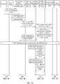
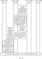
- FIG. 3A and FIG. 3B are a schematic flowchart of another data transmission method according to an embodiment of this application. The method specifically includes the following steps.
- S301 A terminal sends a PDU session establishment request to an access and mobility management function entity.
- the access and mobility management function entity selects a session management function entity.
- the access and mobility management function entity sends a PDU session establishment context request to the session management function entity.
- S304 The session management function entity sends a subscription information request to a unified data management entity.
- the unified data management entity returns a subscription information response, where the subscription information response carries a correspondence between a QFI and an inter-packet time interval.
- the session management function entity sends a PDU session establishment context response to the access and mobility management function entity.
- S307 Perform security authentication on a PDU session.
- the session management function entity selects a policy control function entity.
- S309 The session management function entity and the policy control function entity establish a session management policy.
- the SMF initiates a session management policy establishment request to the PCF.
- the PCF returns a default policy and charging control (Policy Control and Charging, PCC) rule to the SMF, including a bandwidth, a 5G quality of service identifier (5G QoS Identifier, 5QI), and the like.
- Policy Control and Charging PCC
- PCC Policy Control and Charging
- the interaction procedure herein may alternatively be that the SMF sends a session management policy modification request to the PCF, to modify the established session management policy.
- S310 The session management function entity selects a user plane function entity.
- S311 The session management function entity and the policy control function entity modify the session management policy.
- the SMF may report some subscription information to the PCF.
- the PCF generates a dynamic PCC rule based on the subscription information and returns the dynamic PCC rule to the SMF.
- the PCF delivers the PCC rule obtained after modification to the SMF, including a bandwidth and a 5QI.
- the session management function entity sends a session establishment request to the user plane function entity, and the session establishment request carries the correspondence between the QFI and the inter-packet time interval.
- the session management function entity sends an N4 session establishment request to the user plane function entity, where the N4 session establishment request carries the correspondence between the QFI and the inter-packet time interval.
- the user plane function entity establishes an uplink gate queue based on the correspondence between the QFI and the inter-packet time interval, and establishes a mapping relationship between the QFI and the uplink gate queue.
- S314 The user plane function entity returns an N4 session establishment response to the session management function entity.
- the session management function entity sends an N1N2 transfer message to the access and mobility management function entity, where the N1N2 transfer message carries the correspondence between the QFI and the inter-packet time interval.
- the access and mobility management function entity sends an N2 PDU session establishment request to a base station, where the N2 PDU session establishment request carries the correspondence between the QFI and the inter-packet time interval.
- the base station establishes a downlink gate queue based on the correspondence between the QFI and the inter-packet time interval and establishes a mapping relationship between the QFI and the downlink gate queue.
- the UPF and the (R)AN that is, the base station
- the UPF and the (R)AN each may establish a gate queue, and establish a mapping relationship between the gate queue and the QFI.
- the data packet may be shaped, to implement periodic scheduling.
- the inter-packet time interval of the data packet is 10000 microseconds ( ⁇ s)
- a size of the data packet is 100 bytes (byte)
- the gate queue used for data packet shaping can accommodate a maximum of 200 data packets at the same time.
- the gate queue buffers the data packet, and may send a data packet every 10000 ⁇ s.
- the periodic scheduling herein may alternatively be: set a periodicity slightly greater than the inter-packet time interval, to implement setting of the gate queue and opening and closing of a gate. This is not limited in this embodiment of this application.
- corresponding gate queues may be separately selected for different data packets based on QFIs corresponding to the service flows, to perform parallel processing.
- corresponding gate queues may be sequentially selected based on priorities or latency requirements of services, to perform sequential processing; or a task may be migrated to another node device, a related correspondence between a QFI and an inter-packet time interval is sent to the node device, and the node device completes periodic scheduling transmission. This is not limited in this embodiment of this application.
- the user plane function entity is a target user plane function entity obtained after the UPF reselection.
- the SMF selects a target UPF, and the SMF sends the correspondence between the QFI and the inter-packet time interval to the target UPF, so that the target UPF establishes an uplink gate queue based on the correspondence between the QFI and the inter-packet time interval, and establishes a mapping relationship between the uplink gate queue and the QFI.
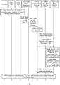
- the procedure includes the following steps.
- S401 A terminal, a source base station (source RAN), and a target base station (target RAN) complete a preparation procedure and a handover procedure of base station handover.
- source RAN source base station
- target RAN target base station
- step S401 the procedure further includes:
- the target base station sends an N2 path switch request to an access and mobility management function entity.
- the access and mobility management function entity sends a user plane function entity reselection indication message to a session management function entity.
- S404 The session management function entity reselects a user plane function entity.
- the session management function entity sends a session establishment request to the target user plane function entity (target UPF), where the session establishment request carries a correspondence between a QFI and an inter-packet time interval.
- target UPF target user plane function entity
- the target user plane function entity establishes an uplink gate queue based on the correspondence between the QFI and the inter-packet time interval, and establishes a mapping relationship between the uplink gate queue and the QFI.
- the target user plane function entity sends a session establishment response to the SMF.
- S408 Complete a remaining part of a base station handover procedure including user plane function entity reselection.
- the SMF sends a session establishment request carrying the correspondence between the QFI and the inter-packet time interval to the target UPF, so that the target UPF can establish a corresponding uplink gate queue based on the received correspondence between the QFI and the inter-packet time interval, and establish a mapping relationship between the uplink gate queue and the QFI.
- the target UPF may also shape the uplink data packet, to implement periodic scheduling.
- the source UPF before the base station handover and the target UPF after the base station handover and the UPF reselection each can periodically schedule and send the uplink data packet.
- a base station receives an uplink data packet from a terminal, and the base station may determine a data radio bearer (Data Radio Bearer, DRB) based on a packet data convergence protocol (Packet Data Convergence Protocol, PDCP) entity and determine a QFI based on a correspondence between the DRB and the QFI. Then, the base station may encapsulate the QFI into the uplink data packet sent by the terminal.
- DRB Data Radio Bearer
- PDCP Packet Data Convergence Protocol
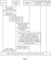
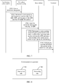
- FIG. 5 is a schematic flowchart of still another data transmission method according to an embodiment of this application. The method includes the following steps.
- S501 UE sends an uplink data packet to a base station.
- the base station determines a corresponding DRB based on a PDCP entity, determines a QFI based on a correspondence between the DRB and the QFI, and encapsulates the QFI into the uplink data packet.
- the base station sends, to a UPF, the uplink data packet carrying the Q FI .
- the UPF determines a corresponding uplink gate queue based on the QFI included in the uplink data packet carrying the QFI, and places the uplink data packet in the uplink gate queue for scheduling.
- the UPF periodically sends the uplink data packet in the uplink gate queue to an application server (APP server).
- APP server application server
- the UPF may obtain an inter-packet time interval based on the correspondence, then configure the corresponding uplink gate queue based on the inter-packet time interval and set a quantity of uplink data packets that can be accommodated in the uplink gate queue and a periodicity from opening to closing a gate by the uplink gate queue.
- the inter-packet time interval of the uplink data packet is 10000 microseconds ( ⁇ s)
- a size of the uplink data packet is 100 bytes (byte)
- the UPF configures that the uplink gate queue used for uplink data packet shaping can accommodate a maximum of 200 data packets at the same time.
- the UPF After receiving the uplink data packet, the UPF buffers the uplink data packet in the uplink gate queue, and then may periodically schedule and send the uplink data packet based on a sending periodicity determined based on the inter-packet time interval. For example, the UPF sends an uplink data packet every 10000 ⁇ s.
- periodic scheduling herein may alternatively be: set a periodicity slightly greater than the inter-packet time interval, to implement setting of the uplink gate queue and opening and closing of the gate. This is not limited in this embodiment of this application.
- the uplink data packet periodically and accurately arrives at a receive end device.
- the base station is a target base station after handover.
- a source base station may send a handover request to the target base station, where the handover request includes the correspondence between the QFI and the inter-packet time interval, so that the target base station establishes a downlink gate queue based on the correspondence between the QFI and the inter-packet time interval, and establishes a mapping relationship between the downlink gate queue and the QFI.
- the procedure includes the following steps.
- a source base station delivers a measurement configuration message to a terminal.
- S602 The terminal reports a measurement result to the source base station.
- the source base station determines, based on the measurement result reported by the UR, whether to perform base station handover. If a result obtained through determining is that base station handover needs to be performed, a subsequent step is performed.
- the source base station sends a handover request to a target base station, where the handover request includes a correspondence between a QFI and an inter-packet time interval.
- the target base station determines whether to agree to the handover, and if the target base station agrees to the handover, the target base station establishes a downlink gate queue based on the correspondence between the QFI and the inter-packet time interval, and establishes a mapping relationship between the downlink gate queue and the QFI.
- the target base station sends a handover request response to the source base station.
- the source base station sends a handover command to the terminal.
- the source RAN sends, to the target RAN, the handover request carrying the correspondence between the QFI and the inter-packet time interval, so that the target RAN after the handover can establish the corresponding downlink gate queue and establish the mapping relationship between the downlink gate queue and the QFI.
- the target RAN may shape the downlink data packet, to implement periodic scheduling.
- the source base station before the base station handover and the target base station after the base station handover each can periodically schedule and send the downlink data packet.
- a UPF may determine a QFI based on a service data flow filter (Service Data flow Filter, SDF), and then the UPF encapsulates the QFI into the downlink data packet sent by the application server.
- SDF Service Data flow Filter
- FIG. 7 is a schematic flowchart of still another data transmission method according to an embodiment of this application. The method includes the following steps.
- S701 An application server (APP server) sends a downlink data packet to a user plane function entity.
- APP server application server
- the user plane function entity determines a corresponding QFI based on a service data flow filter SDF, and encapsulates the QFI into the downlink data packet.
- the user plane function entity sends, to a base station, the downlink data packet carrying the QFI.
- the base station determines a corresponding downlink gate queue based on the QFI included in the downlink data packet carrying the QFI, and places the downlink data packet in the downlink gate queue for scheduling.
- S705 The base station periodically sends, to a terminal, the downlink data packet in the downlink gate queue.
- the base station may obtain an inter-packet time interval based on the correspondence, then configure the corresponding downlink gate queue based on the inter-packet time interval, and set a quantity of downlink data packets that can be accommodated in the downlink gate queue and a periodicity from opening to closing a gate by the downlink gate queue.
- the inter-packet time interval of the downlink data packet is 10000 microseconds ( ⁇ s)
- a size of the downlink data packet is 100 bytes (byte)
- the base station configures that the downlink gate queue used for downlink data packet shaping can accommodate a maximum of 200 downlink data packets at the same time.
- the base station After receiving the downlink data packet, the base station buffers the downlink data packet in the downlink gate queue, and then may periodically schedule and send the downlink data packet based on a sending periodicity determined based on the inter-packet time interval. For example, the base station sends a downlink data packet every 10000 ⁇ s.
- periodic scheduling herein may alternatively be: set a periodicity slightly greater than the inter-packet time interval, to implement setting of the downlink gate queue and opening and closing of the gate. This is not limited in this embodiment of this application.
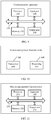
- FIG. 8 is a schematic composition diagram of a communications apparatus according to an embodiment of this application.
- the communications apparatus includes:
- the communications apparatus is a user plane function entity
- the upper-level sending device is a base station
- the data packet is an uplink data packet
- the transceiver unit 100 is specifically configured to receive the correspondence from a session management function entity.
- the communications apparatus is a base station
- the upper-level sending device is a user plane function entity
- the data packet is a downlink data packet.
- the transceiver unit 100 is specifically configured to receive the correspondence from an access and mobility management function entity; and the transceiver unit 100 is further configured to send the correspondence to a target base station.
- the transceiver unit 100 is specifically configured to receive the correspondence from a source base station.
- the communications apparatus may perform any operation of the UPF in FIG. 3A and FIG. 3B , the target UPF in FIG. 4 , or the UPF in FIG. 5 .
- the communications apparatus may perform any operation of the base station in FIG. 3A and FIG. 3B , the target base station in FIG. 6 , or the base station in FIG. 7 .
- FIG. 9 is a schematic composition diagram of another communications apparatus according to an embodiment of this application.
- the communications apparatus may include a processor 110, a memory 120, and a bus 130.
- the processor 110 and the memory 120 are connected by using the bus 130.
- the memory 120 is configured to store an instruction.
- the processor 110 is configured to execute the instruction stored in the memory 120, to implement any operation of the UPF in FIG. 3A and FIG. 3B , the target UPF in FIG. 4 , or the UPF in FIG. 5 , or any operation of the base station in FIG. 3A and FIG. 3B , the target base station in FIG. 6 , or the base station in FIG. 7 .
- the apparatus may further include an input port 140 and an output port 150.
- the processor 110, the memory 120, the input port 140, and the output port 150 may be connected by using the bus 130.
- the processor 110 is configured to execute the instruction stored in the memory 120, to control the input port 140 to receive a signal, control the output port 150 to send a signal, and complete the steps performed by the apparatus in the foregoing methods.
- the input port 140 and the output port 150 may be a same physical entity or different physical entities. When the input port 140 and the output port 150 are the same physical entity, the input port 140 and the output port 150 may be collectively referred to as an input/output port.
- the memory 120 may be integrated into the processor 110, or may be separated from the processor 110.
- functions of the input port 140 and the output port 150 are implemented by using a transceiver circuit or a dedicated transceiver chip. It may be considered to implement the processor 110 by using a dedicated processing chip, a processing circuit, a processor, or a general-purpose chip.
- a general-purpose computer it may be considered to implement the apparatus provided in this embodiment of this application by using a general-purpose computer.
- program code that is used to implement functions of the processor 110, the input port 140, and the output port 150 is stored in the memory, and a general-purpose processor implements the functions of the processor 110, the input port 140, and the output port 150 by executing the code in the memory.
- FIG. 10 is a schematic composition diagram of a session management function entity according to an embodiment of this application.
- the session management functional entity includes:
- the communications apparatus is a base station; and the transceiver unit 300 is specifically configured to send the correspondence to the base station through an access and mobility management function entity.
- the communications apparatus is a user plane function entity.
- the user plane function entity is a target user plane function entity
- the transceiver unit 300 before the transceiver unit 300 sends the correspondence to the communications apparatus, the transceiver unit 300 is further configured to receive, from an access and mobility management function entity, a request for reselecting a user plane function entity; and the processing unit 400 is further configured to select the target user plane function entity; and the transceiver unit 300 is further configured to send the correspondence to the target user plane function entity.
- the session management function entity in FIG. 10 may further perform another operation in FIG. 2 to FIG. 4 . Details are not described herein again.
- FIG. 11 is a schematic composition diagram of another session management function entity according to an embodiment of this application.
- the session management function entity may include a processor 210, a memory 220, and a bus 230.
- the processor 210 and the memory 220 are connected by using the bus 230.
- the memory 220 is configured to store an instruction.
- the processor 210 is configured to execute the instruction stored in the memory 220, to implement operations of the session management function entity in the methods corresponding to FIG. 2 to FIG. 4 .
- the session management function entity may further include an input port 240 and an output port 250.
- the processor 210, the memory 220, the input port 240, and the output port 250 may be connected by using the bus 230.
- the processor 210 is configured to execute the instruction stored in the memory 220, to control the input port 240 to receive a signal, control the output port 250 to send a signal, and complete the steps performed by the session management function entity in the foregoing methods.
- the input port 240 and the output port 250 may be a same physical entity or different physical entities. When the input port 140 and the output port 150 are the same physical entity, the input port 140 and the output port 150 may be collectively referred to as an input/output port.
- the memory 220 may be integrated in the processor 210, or may be disposed separately from the processor 210.
- functions of the input port 240 and the output port 250 are implemented by using a transceiver circuit or a dedicated transceiver chip. It may be considered to implement the processor 210 by using a dedicated processing chip, a processing circuit, a processor, or a general-purpose chip.
- a general-purpose computer it may be considered to implement the apparatus provided in this embodiment of this application by using a general-purpose computer.
- program code that is used to implement functions of the processor 210, the input port 240, and the output port 250 is stored in the memory, and a general-purpose processor implements the functions of the processor 210, the input port 240, and the output port 250 by executing the code in the memory.
- FIG. 9 and FIG. 11 show only one memory and only one processor.
- a controller may include a plurality of processors and a plurality of memories.
- the memory may also be referred to as a storage medium, a storage device, or the like. This is not limited in this embodiment of this application.
- the processor may be a central processing unit (Central Processing Unit, "CPU” for short), or the processor may be another general purpose processor, a digital signal processor (DSP), an application-specific integrated circuit (ASIC), a field programmable gate array (FPGA), or another programmable logic device, discrete gate or transistor logic device, discrete hardware component, or the like.
- the general purpose processor may be a microprocessor, or the processor may be any conventional processor or the like.
- the memory may include a read-only memory and a random access memory, and provide an instruction and data to the processor.
- a part of the memory may further include a non-volatile random access memory.
- the bus may further include a power bus, a control bus, a status signal bus, and the like, in addition to a data bus.
- a power bus may further include a power bus, a control bus, a status signal bus, and the like, in addition to a data bus.
- various types of buses in the figures are marked as the bus.
- steps in the foregoing methods can be implemented by using a hardware integrated logical circuit in the processor, or by using instructions in a form of software.
- the steps of the methods disclosed with reference to the embodiments of this application may be directly performed by a hardware processor, or may be performed by using a combination of hardware in the processor and a software module.
- the software module may be located in a mature storage medium in the art, such as a random access memory, a flash memory, a read-only memory, a programmable read-only memory, an electrically erasable programmable memory, or a register.
- the storage medium is located in the memory, and the processor reads information in the memory and completes the steps in the foregoing methods in combination with hardware of the processor. To avoid repetition, details are not described herein again.
- an embodiment of this application further provides a data transmission system, including the foregoing UPF and base station.
- a data transmission system including the foregoing UPF and base station.
- sequence numbers of the foregoing processes do not mean execution sequences in various embodiments of this application.
- the execution sequences of the processes should be determined according to functions and internal logic of the processes, and should not be construed as any limitation on the implementation processes of the embodiments of this application.
- the disclosed system, apparatus, and method may be implemented in other manners.
- the described apparatus embodiment is merely an example.
- the unit division is merely logical function division and may be other division in actual implementation.
- a plurality of units or components may be combined or integrated into another system, or some features may be ignored or not performed.
- the displayed or discussed mutual couplings or direct couplings or communication connections may be implemented by using some interfaces.
- the indirect couplings or communication connections between the apparatuses or units may be implemented in electronic, mechanical, or other forms.
- All or some of the foregoing embodiments may be implemented by using software, hardware, firmware, or any combination thereof.
- the embodiments may be implemented completely or partially in a form of a computer program product.
- the computer program product includes one or more computer instructions.
- the computer may be a general-purpose computer, a dedicated computer, a computer network, or another programmable apparatus.
- the computer instructions may be stored in a computer-readable storage medium or may be transmitted from a computer-readable storage medium to another computer-readable storage medium.
- the computer instructions may be transmitted from a website, computer, server, or data center to another website, computer, server, or data center in a wired (for example, a coaxial cable, an optical fiber, or a digital subscriber line (DSL)) or wireless (for example, infrared, radio, or microwave) manner.
- the computer-readable storage medium may be any usable medium accessible by the computer, or a data storage device, such as a server or a data center, integrating one or more usable media.
- the usable medium may be a magnetic medium (for example, a floppy disk, a hard disk, or a magnetic tape), an optical medium (for example, a DVD), a semiconductor medium (for example, a solid-state drive Solid State Disk (SSD)), or the like.
- a magnetic medium for example, a floppy disk, a hard disk, or a magnetic tape
- an optical medium for example, a DVD
- a semiconductor medium for example, a solid-state drive Solid State Disk (SSD)
Landscapes
- Engineering & Computer Science (AREA)
- Computer Networks & Wireless Communication (AREA)
- Signal Processing (AREA)
- Mobile Radio Communication Systems (AREA)
Applications Claiming Priority (2)
| Application Number | Priority Date | Filing Date | Title |
|---|---|---|---|
| CN201810107022.6A CN110138813B (zh) | 2018-02-02 | 2018-02-02 | 一种传输数据的方法、通信装置及用户面功能实体 |
| PCT/CN2019/071786 WO2019149063A1 (fr) | 2018-02-02 | 2019-01-15 | Procédé de transmission de données, appareil de communication et entité fonctionnelle de plan d'utilisateur |
Publications (3)
| Publication Number | Publication Date |
|---|---|
| EP3720183A1 true EP3720183A1 (fr) | 2020-10-07 |
| EP3720183A4 EP3720183A4 (fr) | 2021-03-03 |
| EP3720183B1 EP3720183B1 (fr) | 2022-03-09 |
Family
ID=67479128
Family Applications (1)
| Application Number | Title | Priority Date | Filing Date |
|---|---|---|---|
| EP19747478.6A Active EP3720183B1 (fr) | 2018-02-02 | 2019-01-15 | Procédé de transmission de données, appareil de communication et entité fonctionnelle de plan d'utilisateur |
Country Status (4)
| Country | Link |
|---|---|
| US (1) | US11432205B2 (fr) |
| EP (1) | EP3720183B1 (fr) |
| CN (1) | CN110138813B (fr) |
| WO (1) | WO2019149063A1 (fr) |
Families Citing this family (12)
| Publication number | Priority date | Publication date | Assignee | Title |
|---|---|---|---|---|
| JP7402887B2 (ja) * | 2019-10-04 | 2023-12-21 | 株式会社Nttドコモ | ユーザプレーン装置、通信システム、及びバッファ方法 |
| EP3820092B1 (fr) * | 2019-11-07 | 2026-03-25 | Nokia Technologies Oy | Système de communication |
| CN113630816A (zh) * | 2020-05-06 | 2021-11-09 | 华为技术有限公司 | 一种数据传输方法及装置 |
| CN114173384B (zh) * | 2020-09-10 | 2025-02-11 | 大唐移动通信设备有限公司 | QoS控制方法、装置及处理器可读存储介质 |
| CN114979963A (zh) * | 2021-02-25 | 2022-08-30 | 华为技术有限公司 | 组播/广播业务的通信方法、装置及系统 |
| CN115277583B (zh) * | 2021-04-30 | 2025-06-17 | 华为技术有限公司 | 一种业务流识别方法及装置 |
| US11777795B2 (en) * | 2021-09-30 | 2023-10-03 | Cisco Technology, Inc. | Local breakout of user plan function at enterprise 5G radio access network |
| CN116530141A (zh) | 2021-12-29 | 2023-08-01 | 新华三技术有限公司 | 确定性流传输方法及设备 |
| CN116418756A (zh) * | 2021-12-30 | 2023-07-11 | 南京盛科通信有限公司 | 数据流的发送方法、装置、存储介质和电子装置 |
| CN116647894A (zh) * | 2022-02-15 | 2023-08-25 | 大唐移动通信设备有限公司 | 数据调度方法、装置、设备及存储介质 |
| EP4515853A2 (fr) * | 2022-05-05 | 2025-03-05 | Huawei Technologies Co., Ltd. | Corrélation de flux et classification multimédia http |
| CN114866482B (zh) * | 2022-07-07 | 2022-11-15 | 中汽创智科技有限公司 | 一种数据流传输方法和装置 |
Family Cites Families (8)
| Publication number | Priority date | Publication date | Assignee | Title |
|---|---|---|---|---|
| US9042252B2 (en) * | 2012-11-13 | 2015-05-26 | Netronome Systems, Incorporated | Inter-packet interval prediction learning algorithm |
| CN103905336B (zh) * | 2014-04-24 | 2017-04-19 | 河北工程大学 | 一种基于网络编码技术的SIEPON中QoS感知的调度方法 |
| US10769212B2 (en) * | 2015-07-31 | 2020-09-08 | Netapp Inc. | Extensible and elastic data management services engine external to a storage domain |
| CN105978853B (zh) * | 2016-04-18 | 2020-08-14 | 腾讯科技(深圳)有限公司 | 一种会话调度方法、调度服务器及终端 |
| CN108307502B (zh) * | 2016-08-25 | 2023-05-23 | 中兴通讯股份有限公司 | 信息发送、接收方法及装置、基站、终端 |
| CN107018542A (zh) * | 2017-03-27 | 2017-08-04 | 中兴通讯股份有限公司 | 网络系统中状态信息的处理方法、装置及存储介质 |
| CN107332877A (zh) * | 2017-06-02 | 2017-11-07 | 上海金大师网络科技有限公司 | 基于消息路由且缓存上下文的去状态行情网关系统 |
| CN109548089B (zh) * | 2017-08-08 | 2023-05-09 | 中国移动通信有限公司研究院 | 反射QoS指示标识的发送、检测方法、网络设备及终端 |
-
2018
- 2018-02-02 CN CN201810107022.6A patent/CN110138813B/zh active Active
-
2019
- 2019-01-15 WO PCT/CN2019/071786 patent/WO2019149063A1/fr not_active Ceased
- 2019-01-15 EP EP19747478.6A patent/EP3720183B1/fr active Active
-
2020
- 2020-07-31 US US16/944,580 patent/US11432205B2/en active Active
Also Published As
| Publication number | Publication date |
|---|---|
| CN110138813B (zh) | 2021-11-19 |
| EP3720183A4 (fr) | 2021-03-03 |
| EP3720183B1 (fr) | 2022-03-09 |
| US20200367114A1 (en) | 2020-11-19 |
| WO2019149063A1 (fr) | 2019-08-08 |
| US11432205B2 (en) | 2022-08-30 |
| CN110138813A (zh) | 2019-08-16 |
Similar Documents
| Publication | Publication Date | Title |
|---|---|---|
| EP3720183B1 (fr) | Procédé de transmission de données, appareil de communication et entité fonctionnelle de plan d'utilisateur | |
| CA3094110C (fr) | Procede et dispositif de communication | |
| CN114189908B (zh) | 通信方法、装置、设备及存储介质 | |
| CN110661837B (zh) | 服务质量的控制方法和装置 | |
| KR20210010629A (ko) | 서비스 품질 모니터링 방법 및 시스템, 및 디바이스 | |
| KR20210103557A (ko) | 시간 민감 통신 서비스 품질을 지원하는 방법 및 통신 기기 | |
| EP3962157B1 (fr) | Procédés et appareils de détermination de mdbv | |
| JP2022501929A (ja) | データ伝送方法及び装置 | |
| US12382344B2 (en) | Methods and apparatus for establishing a sidelink radio bearer | |
| EP4485996A1 (fr) | Procédé et appareil de communication | |
| US20250126614A1 (en) | Managing configured grants for xr applications | |
| US11042408B2 (en) | Device, system, and resource allocation method | |
| EP4354948A1 (fr) | Procédé, dispositif et système de communication | |
| EP4561148A1 (fr) | Procédé et appareil de communication | |
| CN111447026B (zh) | 处理数据的方法和处理数据的装置 | |
| EP4462916A2 (fr) | Procédé et appareil de communication | |
| WO2020169039A1 (fr) | Procédé et dispositif de gestion de politique | |
| US20240114367A1 (en) | Mobility Measurement Reporting for XR Services | |
| WO2024152858A1 (fr) | Procédé et appareil de rapport de retard, et équipement utilisateur et dispositif côté réseau | |
| US12501308B2 (en) | Mapping data packets to data radio bearers based on corresponding packet delay budgets | |
| WO2023160116A1 (fr) | Procédé et appareil de communication | |
| EP3506673A1 (fr) | Procédé de communication sans fil, dispositif terminal et dispositif de réseau d'accès | |
| EP4580242A1 (fr) | Procédé et appareil servant à établir une règle de qs | |
| EP4462908A1 (fr) | Procédé et appareil de communication | |
| AU2023321265A1 (en) | Delay control method and apparatus |
Legal Events
| Date | Code | Title | Description |
|---|---|---|---|
| STAA | Information on the status of an ep patent application or granted ep patent |
Free format text: STATUS: THE INTERNATIONAL PUBLICATION HAS BEEN MADE |
|
| PUAI | Public reference made under article 153(3) epc to a published international application that has entered the european phase |
Free format text: ORIGINAL CODE: 0009012 |
|
| STAA | Information on the status of an ep patent application or granted ep patent |
Free format text: STATUS: REQUEST FOR EXAMINATION WAS MADE |
|
| 17P | Request for examination filed |
Effective date: 20200701 |
|
| AK | Designated contracting states |
Kind code of ref document: A1 Designated state(s): AL AT BE BG CH CY CZ DE DK EE ES FI FR GB GR HR HU IE IS IT LI LT LU LV MC MK MT NL NO PL PT RO RS SE SI SK SM TR |
|
| AX | Request for extension of the european patent |
Extension state: BA ME |
|
| A4 | Supplementary search report drawn up and despatched |
Effective date: 20210129 |
|
| RIC1 | Information provided on ipc code assigned before grant |
Ipc: H04L 12/851 20130101ALI20210125BHEP Ipc: H04W 36/14 20090101ALI20210125BHEP Ipc: H04W 88/18 20090101ALN20210125BHEP Ipc: H04W 28/12 20090101ALN20210125BHEP Ipc: H04W 88/08 20090101ALN20210125BHEP Ipc: H04L 12/863 20130101ALI20210125BHEP Ipc: H04L 12/875 20130101ALI20210125BHEP Ipc: H04L 29/06 20060101ALN20210125BHEP Ipc: H04W 36/00 20090101AFI20210125BHEP |
|
| DAV | Request for validation of the european patent (deleted) | ||
| DAX | Request for extension of the european patent (deleted) | ||
| RIC1 | Information provided on ipc code assigned before grant |
Ipc: H04L 29/06 20060101ALN20210812BHEP Ipc: H04W 28/12 20090101ALN20210812BHEP Ipc: H04W 88/18 20090101ALN20210812BHEP Ipc: H04W 88/08 20090101ALN20210812BHEP Ipc: H04L 12/875 20130101ALI20210812BHEP Ipc: H04L 12/863 20130101ALI20210812BHEP Ipc: H04L 12/851 20130101ALI20210812BHEP Ipc: H04W 36/14 20090101ALI20210812BHEP Ipc: H04W 36/00 20090101AFI20210812BHEP |
|
| GRAP | Despatch of communication of intention to grant a patent |
Free format text: ORIGINAL CODE: EPIDOSNIGR1 |
|
| RIC1 | Information provided on ipc code assigned before grant |
Ipc: H04L 29/06 20060101ALN20210906BHEP Ipc: H04W 28/12 20090101ALN20210906BHEP Ipc: H04W 88/18 20090101ALN20210906BHEP Ipc: H04W 88/08 20090101ALN20210906BHEP Ipc: H04L 12/875 20130101ALI20210906BHEP Ipc: H04L 12/863 20130101ALI20210906BHEP Ipc: H04L 12/851 20130101ALI20210906BHEP Ipc: H04W 36/14 20090101ALI20210906BHEP Ipc: H04W 36/00 20090101AFI20210906BHEP |
|
| STAA | Information on the status of an ep patent application or granted ep patent |
Free format text: STATUS: GRANT OF PATENT IS INTENDED |
|
| GRAJ | Information related to disapproval of communication of intention to grant by the applicant or resumption of examination proceedings by the epo deleted |
Free format text: ORIGINAL CODE: EPIDOSDIGR1 |
|
| GRAP | Despatch of communication of intention to grant a patent |
Free format text: ORIGINAL CODE: EPIDOSNIGR1 |
|
| INTG | Intention to grant announced |
Effective date: 20211014 |
|
| INTG | Intention to grant announced |
Effective date: 20211027 |
|
| GRAS | Grant fee paid |
Free format text: ORIGINAL CODE: EPIDOSNIGR3 |
|
| GRAA | (expected) grant |
Free format text: ORIGINAL CODE: 0009210 |
|
| STAA | Information on the status of an ep patent application or granted ep patent |
Free format text: STATUS: THE PATENT HAS BEEN GRANTED |
|
| AK | Designated contracting states |
Kind code of ref document: B1 Designated state(s): AL AT BE BG CH CY CZ DE DK EE ES FI FR GB GR HR HU IE IS IT LI LT LU LV MC MK MT NL NO PL PT RO RS SE SI SK SM TR |
|
| REG | Reference to a national code |
Ref country code: CH Ref legal event code: EP Ref country code: AT Ref legal event code: REF Ref document number: 1475148 Country of ref document: AT Kind code of ref document: T Effective date: 20220315 |
|
| REG | Reference to a national code |
Ref country code: DE Ref legal event code: R096 Ref document number: 602019012437 Country of ref document: DE |
|
| REG | Reference to a national code |
Ref country code: IE Ref legal event code: FG4D |
|
| REG | Reference to a national code |
Ref country code: LT Ref legal event code: MG9D |
|
| REG | Reference to a national code |
Ref country code: NL Ref legal event code: MP Effective date: 20220309 |
|
| PG25 | Lapsed in a contracting state [announced via postgrant information from national office to epo] |
Ref country code: SE Free format text: LAPSE BECAUSE OF FAILURE TO SUBMIT A TRANSLATION OF THE DESCRIPTION OR TO PAY THE FEE WITHIN THE PRESCRIBED TIME-LIMIT Effective date: 20220309 Ref country code: RS Free format text: LAPSE BECAUSE OF FAILURE TO SUBMIT A TRANSLATION OF THE DESCRIPTION OR TO PAY THE FEE WITHIN THE PRESCRIBED TIME-LIMIT Effective date: 20220309 Ref country code: NO Free format text: LAPSE BECAUSE OF FAILURE TO SUBMIT A TRANSLATION OF THE DESCRIPTION OR TO PAY THE FEE WITHIN THE PRESCRIBED TIME-LIMIT Effective date: 20220609 Ref country code: LT Free format text: LAPSE BECAUSE OF FAILURE TO SUBMIT A TRANSLATION OF THE DESCRIPTION OR TO PAY THE FEE WITHIN THE PRESCRIBED TIME-LIMIT Effective date: 20220309 Ref country code: HR Free format text: LAPSE BECAUSE OF FAILURE TO SUBMIT A TRANSLATION OF THE DESCRIPTION OR TO PAY THE FEE WITHIN THE PRESCRIBED TIME-LIMIT Effective date: 20220309 Ref country code: BG Free format text: LAPSE BECAUSE OF FAILURE TO SUBMIT A TRANSLATION OF THE DESCRIPTION OR TO PAY THE FEE WITHIN THE PRESCRIBED TIME-LIMIT Effective date: 20220609 |
|
| REG | Reference to a national code |
Ref country code: AT Ref legal event code: MK05 Ref document number: 1475148 Country of ref document: AT Kind code of ref document: T Effective date: 20220309 |
|
| PG25 | Lapsed in a contracting state [announced via postgrant information from national office to epo] |
Ref country code: LV Free format text: LAPSE BECAUSE OF FAILURE TO SUBMIT A TRANSLATION OF THE DESCRIPTION OR TO PAY THE FEE WITHIN THE PRESCRIBED TIME-LIMIT Effective date: 20220309 Ref country code: GR Free format text: LAPSE BECAUSE OF FAILURE TO SUBMIT A TRANSLATION OF THE DESCRIPTION OR TO PAY THE FEE WITHIN THE PRESCRIBED TIME-LIMIT Effective date: 20220610 Ref country code: FI Free format text: LAPSE BECAUSE OF FAILURE TO SUBMIT A TRANSLATION OF THE DESCRIPTION OR TO PAY THE FEE WITHIN THE PRESCRIBED TIME-LIMIT Effective date: 20220309 |
|
| PG25 | Lapsed in a contracting state [announced via postgrant information from national office to epo] |
Ref country code: NL Free format text: LAPSE BECAUSE OF FAILURE TO SUBMIT A TRANSLATION OF THE DESCRIPTION OR TO PAY THE FEE WITHIN THE PRESCRIBED TIME-LIMIT Effective date: 20220309 |
|
| PG25 | Lapsed in a contracting state [announced via postgrant information from national office to epo] |
Ref country code: SM Free format text: LAPSE BECAUSE OF FAILURE TO SUBMIT A TRANSLATION OF THE DESCRIPTION OR TO PAY THE FEE WITHIN THE PRESCRIBED TIME-LIMIT Effective date: 20220309 Ref country code: SK Free format text: LAPSE BECAUSE OF FAILURE TO SUBMIT A TRANSLATION OF THE DESCRIPTION OR TO PAY THE FEE WITHIN THE PRESCRIBED TIME-LIMIT Effective date: 20220309 Ref country code: RO Free format text: LAPSE BECAUSE OF FAILURE TO SUBMIT A TRANSLATION OF THE DESCRIPTION OR TO PAY THE FEE WITHIN THE PRESCRIBED TIME-LIMIT Effective date: 20220309 Ref country code: PT Free format text: LAPSE BECAUSE OF FAILURE TO SUBMIT A TRANSLATION OF THE DESCRIPTION OR TO PAY THE FEE WITHIN THE PRESCRIBED TIME-LIMIT Effective date: 20220711 Ref country code: ES Free format text: LAPSE BECAUSE OF FAILURE TO SUBMIT A TRANSLATION OF THE DESCRIPTION OR TO PAY THE FEE WITHIN THE PRESCRIBED TIME-LIMIT Effective date: 20220309 Ref country code: EE Free format text: LAPSE BECAUSE OF FAILURE TO SUBMIT A TRANSLATION OF THE DESCRIPTION OR TO PAY THE FEE WITHIN THE PRESCRIBED TIME-LIMIT Effective date: 20220309 Ref country code: CZ Free format text: LAPSE BECAUSE OF FAILURE TO SUBMIT A TRANSLATION OF THE DESCRIPTION OR TO PAY THE FEE WITHIN THE PRESCRIBED TIME-LIMIT Effective date: 20220309 Ref country code: AT Free format text: LAPSE BECAUSE OF FAILURE TO SUBMIT A TRANSLATION OF THE DESCRIPTION OR TO PAY THE FEE WITHIN THE PRESCRIBED TIME-LIMIT Effective date: 20220309 |
|
| PG25 | Lapsed in a contracting state [announced via postgrant information from national office to epo] |
Ref country code: PL Free format text: LAPSE BECAUSE OF FAILURE TO SUBMIT A TRANSLATION OF THE DESCRIPTION OR TO PAY THE FEE WITHIN THE PRESCRIBED TIME-LIMIT Effective date: 20220309 Ref country code: IS Free format text: LAPSE BECAUSE OF FAILURE TO SUBMIT A TRANSLATION OF THE DESCRIPTION OR TO PAY THE FEE WITHIN THE PRESCRIBED TIME-LIMIT Effective date: 20220709 Ref country code: AL Free format text: LAPSE BECAUSE OF FAILURE TO SUBMIT A TRANSLATION OF THE DESCRIPTION OR TO PAY THE FEE WITHIN THE PRESCRIBED TIME-LIMIT Effective date: 20220309 |
|
| REG | Reference to a national code |
Ref country code: DE Ref legal event code: R097 Ref document number: 602019012437 Country of ref document: DE |
|
| PLBE | No opposition filed within time limit |
Free format text: ORIGINAL CODE: 0009261 |
|
| STAA | Information on the status of an ep patent application or granted ep patent |
Free format text: STATUS: NO OPPOSITION FILED WITHIN TIME LIMIT |
|
| PG25 | Lapsed in a contracting state [announced via postgrant information from national office to epo] |
Ref country code: DK Free format text: LAPSE BECAUSE OF FAILURE TO SUBMIT A TRANSLATION OF THE DESCRIPTION OR TO PAY THE FEE WITHIN THE PRESCRIBED TIME-LIMIT Effective date: 20220309 |
|
| 26N | No opposition filed |
Effective date: 20221212 |
|
| PG25 | Lapsed in a contracting state [announced via postgrant information from national office to epo] |
Ref country code: SI Free format text: LAPSE BECAUSE OF FAILURE TO SUBMIT A TRANSLATION OF THE DESCRIPTION OR TO PAY THE FEE WITHIN THE PRESCRIBED TIME-LIMIT Effective date: 20220309 |
|
| PG25 | Lapsed in a contracting state [announced via postgrant information from national office to epo] |
Ref country code: IT Free format text: LAPSE BECAUSE OF FAILURE TO SUBMIT A TRANSLATION OF THE DESCRIPTION OR TO PAY THE FEE WITHIN THE PRESCRIBED TIME-LIMIT Effective date: 20220309 |
|
| REG | Reference to a national code |
Ref country code: CH Ref legal event code: PL |
|
| GBPC | Gb: european patent ceased through non-payment of renewal fee |
Effective date: 20230115 |
|
| PG25 | Lapsed in a contracting state [announced via postgrant information from national office to epo] |
Ref country code: LU Free format text: LAPSE BECAUSE OF NON-PAYMENT OF DUE FEES Effective date: 20230115 |
|
| REG | Reference to a national code |
Ref country code: BE Ref legal event code: MM Effective date: 20230131 |
|
| PG25 | Lapsed in a contracting state [announced via postgrant information from national office to epo] |
Ref country code: LI Free format text: LAPSE BECAUSE OF NON-PAYMENT OF DUE FEES Effective date: 20230131 Ref country code: GB Free format text: LAPSE BECAUSE OF NON-PAYMENT OF DUE FEES Effective date: 20230115 Ref country code: CH Free format text: LAPSE BECAUSE OF NON-PAYMENT OF DUE FEES Effective date: 20230131 |
|
| PG25 | Lapsed in a contracting state [announced via postgrant information from national office to epo] |
Ref country code: FR Free format text: LAPSE BECAUSE OF NON-PAYMENT OF DUE FEES Effective date: 20230131 Ref country code: BE Free format text: LAPSE BECAUSE OF NON-PAYMENT OF DUE FEES Effective date: 20230131 |
|
| PG25 | Lapsed in a contracting state [announced via postgrant information from national office to epo] |
Ref country code: IE Free format text: LAPSE BECAUSE OF NON-PAYMENT OF DUE FEES Effective date: 20230115 |
|
| PG25 | Lapsed in a contracting state [announced via postgrant information from national office to epo] |
Ref country code: MC Free format text: LAPSE BECAUSE OF FAILURE TO SUBMIT A TRANSLATION OF THE DESCRIPTION OR TO PAY THE FEE WITHIN THE PRESCRIBED TIME-LIMIT Effective date: 20220309 |
|
| PG25 | Lapsed in a contracting state [announced via postgrant information from national office to epo] |
Ref country code: MC Free format text: LAPSE BECAUSE OF FAILURE TO SUBMIT A TRANSLATION OF THE DESCRIPTION OR TO PAY THE FEE WITHIN THE PRESCRIBED TIME-LIMIT Effective date: 20220309 |
|
| PG25 | Lapsed in a contracting state [announced via postgrant information from national office to epo] |
Ref country code: CY Free format text: LAPSE BECAUSE OF FAILURE TO SUBMIT A TRANSLATION OF THE DESCRIPTION OR TO PAY THE FEE WITHIN THE PRESCRIBED TIME-LIMIT; INVALID AB INITIO Effective date: 20190115 |
|
| PG25 | Lapsed in a contracting state [announced via postgrant information from national office to epo] |
Ref country code: HU Free format text: LAPSE BECAUSE OF FAILURE TO SUBMIT A TRANSLATION OF THE DESCRIPTION OR TO PAY THE FEE WITHIN THE PRESCRIBED TIME-LIMIT; INVALID AB INITIO Effective date: 20190115 |
|
| PG25 | Lapsed in a contracting state [announced via postgrant information from national office to epo] |
Ref country code: TR Free format text: LAPSE BECAUSE OF FAILURE TO SUBMIT A TRANSLATION OF THE DESCRIPTION OR TO PAY THE FEE WITHIN THE PRESCRIBED TIME-LIMIT Effective date: 20220309 |
|
| PGFP | Annual fee paid to national office [announced via postgrant information from national office to epo] |
Ref country code: DE Payment date: 20251203 Year of fee payment: 8 |