EP3720189A1 - Procédé d'acheminement de données et terminal - Google Patents
Procédé d'acheminement de données et terminal Download PDFInfo
- Publication number
- EP3720189A1 EP3720189A1 EP18894023.3A EP18894023A EP3720189A1 EP 3720189 A1 EP3720189 A1 EP 3720189A1 EP 18894023 A EP18894023 A EP 18894023A EP 3720189 A1 EP3720189 A1 EP 3720189A1
- Authority
- EP
- European Patent Office
- Prior art keywords
- target
- network
- terminal
- identifier
- data packet
- Prior art date
- Legal status (The legal status is an assumption and is not a legal conclusion. Google has not performed a legal analysis and makes no representation as to the accuracy of the status listed.)
- Granted
Links
Images




Classifications
-
- H—ELECTRICITY
- H04—ELECTRIC COMMUNICATION TECHNIQUE
- H04W—WIRELESS COMMUNICATION NETWORKS
- H04W40/00—Communication routing or communication path finding
- H04W40/02—Communication route or path selection, e.g. power-based or shortest path routing
-
- H—ELECTRICITY
- H04—ELECTRIC COMMUNICATION TECHNIQUE
- H04W—WIRELESS COMMUNICATION NETWORKS
- H04W24/00—Supervisory, monitoring or testing arrangements
- H04W24/02—Arrangements for optimising operational condition
-
- H—ELECTRICITY
- H04—ELECTRIC COMMUNICATION TECHNIQUE
- H04L—TRANSMISSION OF DIGITAL INFORMATION, e.g. TELEGRAPHIC COMMUNICATION
- H04L45/00—Routing or path finding of packets in data switching networks
- H04L45/70—Routing based on monitoring results
-
- H—ELECTRICITY
- H04—ELECTRIC COMMUNICATION TECHNIQUE
- H04W—WIRELESS COMMUNICATION NETWORKS
- H04W40/00—Communication routing or communication path finding
- H04W40/24—Connectivity information management, e.g. connectivity discovery or connectivity update
-
- H—ELECTRICITY
- H04—ELECTRIC COMMUNICATION TECHNIQUE
- H04W—WIRELESS COMMUNICATION NETWORKS
- H04W48/00—Access restriction; Network selection; Access point selection
- H04W48/18—Selecting a network or a communication service
Definitions
- This application relates to the field of communications technologies, and in particular, to a data routing method and a terminal.
- network slice network slice
- 5G 5th-generation mobile communications technology
- a network of an operator may be divided into a plurality of network slices based on a user group or a service type.
- Each network slice may include one or more data networks (data network, DN).
- a terminal may simultaneously access a plurality of network slices, the terminal may establish communication connections to a plurality of data networks, and a link of each communication connection corresponds to one network interface card (network interface card, NIC) on the terminal.
- NIC network interface card
- a technical solution used in the prior art is that an application program vendor modifies an application program, so that the application program corresponds to a network interface card on a terminal.
- the terminal may query a network interface card corresponding to the application program.
- uplink data may be sent by using the network interface card corresponding to the application program.
- embodiments of the present invention provide a data routing method and a terminal.
- a first aspect of the embodiments of the present invention provides a data routing method, including the following steps.
- Step A A terminal obtains a target identifier carried in a target data packet, where the target identifier is an identifier corresponding to a target program, and the target program is used to generate the target data packet.
- the target identifier may be set in the target data packet, so that the target identifier carried in the target data packet may be obtained when the target data packet needs to be routed.
- Step B The terminal determines a target network interface card that corresponds to the target identifier and that has a data transmission function, where the target network interface card corresponds to a target data network, the target data network belongs to a target network slice, and a service type supported by the target network slice corresponds to a service type of a session initiated by the target program.
- the target network interface card is a functional entity built in the terminal.
- the virtual network interface card is a virtual interface connected to a transmission control protocol/internet protocol (transmission control protocol/internet protocol, TCP/IP) and a modem (Modem), and the target network interface card corresponds to the target program.
- TCP/IP transmission control protocol/internet protocol
- Modem modem
- Step C The terminal sends the target data packet to the target data network by using the target network interface card. Therefore, the target data network can correspondingly process the target data packet, so that the target DN can serve the target program.
- the terminal may determine a path on which the target data packet of the target program is sent, so that the target data packet of the target program can be accurately sent to the target data network that can serve the target program; in a process of routing the target data packet, a complex change to code of the target program is not needed, and modification in code of a core library of an operating system is also avoided, in other words, a program manufacturer can send a data packet of a program to a corresponding target data network without making a change to the program, effectively ensuring that the data packet is successfully sent.
- step B specifically includes: obtaining a target routing table corresponding to the target identifier, where the target routing table includes a correspondence between the target network interface card and a target network element, which is specifically that the target routing table includes a correspondence between an identifier of the target network interface card and an identifier of the target network element.
- different routing tables correspond to different programs installed on the terminal.
- step C specifically includes: sending the target data packet to the target network element by using the target network interface card, where the target network element is configured to forward the target data packet to the target data network.
- the target network element included in the target routing table is obtained from the target routing table; after receiving the target data packet, the target network element may forward the target data packet to the target data network configured to process the target data packet.
- the terminal may determine a target routing table corresponding to any target program run by the terminal.
- the terminal may determine, based on the target routing table, the path on which the target data packet of the target program is sent, so that the target data packet of the target program can be accurately sent to the data network that can serve the target program, and the data packet can be successfully sent based on the target routing table without a complex change to the code of the target program.
- the method further includes the following steps.
- Step A01 The terminal receives the target data packet sent by the target program.
- Step A02 The terminal determines the target identifier corresponding to the target program. Different programs installed on the terminal one-to-one correspond to different identifiers.
- Step A03 The terminal sets the target identifier in a descriptor of the target data packet. Specifically, the descriptor of the target data packet includes a target field, and the target field is specially used to record a marked value. In this case, the terminal may record the target identifier in the target field.
- Step A01 to step A03 are preprocessing on the target data packet before routing.
- the terminal may set the target identifier in the descriptor of the target data packet. Therefore, when routing the target data packet, the terminal can accurately determine, based on the target identifier, a routing table that can route the target data packet, to improve accuracy of sending the target data packet to the target data network, and reduce table lookup difficulty because the target identifier is shorter than the user identifier, thereby improving efficiency of querying a corresponding target routing table based on the target identifier.
- step A02 a specific process of step A02 in which the terminal determines the target identifier corresponding to the target program is as follows.
- Step A021 The terminal obtains a target user identifier UID carried in the target data packet. Specifically, the terminal may obtain a name of the target program, determine a user identifier corresponding to the name of the target program, and determine the user identifier corresponding to the name of the target program as the target identifier.
- Step A022 The terminal obtains, based on a first correspondence, the target identifier corresponding to the target user identifier UID, where the first correspondence includes correspondences between user identifiers UIDs of different programs and different identifiers.
- Beneficial effects of the method shown in this aspect are as follows: Because the target identifier is shorter than the user identifier, table lookup difficulty is effectively reduced, to improve efficiency of querying the corresponding target routing table based on the target identifier, thereby improving efficiency of routing the target data packet based on the target routing table to send the target routing table to the target data network.
- the method before step B of determining the target network interface card that corresponds to the target identifier and that has the data transmission function is performed, the method further includes a process of creating the target routing table. Details are as follows.
- Step B11 The terminal receives a terminal route selection policy list, where the terminal route selection policy list indicates that there is at least one network slice, and any one of the at least one network slice includes at least one data network.
- Step B12 The terminal determines the target network slice and the target data network based on the terminal route selection policy list. Specifically, the terminal may first obtain the name of the target program, and the terminal may determine, based on the URSP list, slice information (Slice Info) corresponding to the name of the target program.
- the slice info may include at least one network slice.
- the terminal may select, from the at least one network slice, one network slice as a target network slice corresponding to a type of the target program.
- the route selection policy list further includes a plurality of data networks corresponding to the name of the target program.
- the terminal may select one data network from the plurality of data networks as the target data network to serve the target data packet.
- Step B13 The terminal determines the target network element corresponding to the target data network. Specifically, the terminal may send indication information to a core network side, where the indication information includes a name of the target data network selected by the terminal, and the core network side may send an address of the target network element to the terminal based on the indication information.
- Step B14 Determine the target network interface card corresponding to the target network element.
- Step B15 Create the target routing table based on the correspondence between the target network interface card and the target network element.
- the terminal may create the target routing table used to route the target data packet; then, after obtaining the target identifier carried in the target data packet, the terminal may determine the corresponding target routing table based on the target identifier, and the terminal may route the target data packet based on the target routing table to send the target data packet to the target data network; in a process of performing routing based on the target routing table, a complex change to code of the target program is not needed, thereby effectively ensuring that the data packet is successfully sent.
- a second aspect of the embodiments of the present invention provides a data routing apparatus, including: an identifier obtaining module, configured to obtain a target identifier carried in a target data packet, where the target identifier is an identifier corresponding to a target program, and the target program is used to generate the target data packet; and the identifier obtaining module is configured to perform step A in the first aspect of the embodiments of the present invention; a searching module, configured to determine a target network interface card that corresponds to the target identifier and that has a data transmission function, where the target network interface card corresponds to a target data network, the target data network belongs to a target network slice, and a service type supported by the target network slice corresponds to a service type of a session initiated by the target program; and the searching module is configured to perform step B in the first aspect of the embodiments of the present invention; and the target network interface card, configured to send the target data packet to the target data network.
- the target network interface card is configured to perform step C in the first aspect of the embodiment
- the data routing apparatus may determine a path on which the target data packet of the target program is sent, so that the target data packet of the target program can be accurately sent to the target data network that can serve the target program; in a process of routing the target data packet, a complex change to code of the target program is not needed, and modification in code of a core library of an operating system is also avoided, in other words, a program manufacturer can send a data packet of a program to a corresponding target data network without making a change to the program, effectively ensuring that the data packet is successfully sent.
- the identifier obtaining module is specifically configured to obtain a target routing table corresponding to the target identifier, where the target routing table includes a correspondence between the target network interface card and a target network element; and the target network interface card is further configured to send the target data packet to the target network element, and the target network element is configured to forward the target data packet to the target data network.
- the data routing apparatus may determine a target routing table corresponding to any target program run by the terminal.
- the data routing apparatus may determine, based on the target routing table, the path on which the target data packet of the target program is sent, so that the target data packet of the target program can be accurately sent to the data network that can serve the target program, and the data packet can be successfully sent based on the target routing table without a complex change to the code of the target program.
- the data routing apparatus further includes: a first receiving module, configured to receive the target data packet sent by the target program; a first determining module, configured to determine the target identifier corresponding to the target program; and a setting module, configured to set the target identifier in a descriptor of the target data packet.
- the data routing apparatus may perform preprocessing on the target data packet before routing.
- the data routing apparatus may set the target identifier in the descriptor of the target data packet. Therefore, when routing the target data packet, the data routing apparatus can accurately determine, based on the target identifier, a routing table that can route the target data packet, to improve accuracy of sending the target data packet to the target data network, and reduce table lookup difficulty because the target identifier is shorter than the user identifier, thereby improving efficiency of querying a corresponding target routing table based on the target identifier.
- the first determining module includes: a first obtaining module, configured to obtain a target user identifier UID carried in the target data packet; and a second obtaining unit, configured to obtain, based on a first correspondence, the target identifier corresponding to the target user identifier UID, where the first correspondence includes correspondences between user identifiers UIDs of different programs and different identifiers.
- Beneficial effects of the data routing apparatus shown in this aspect are as follows: Because the target identifier is shorter than the user identifier, table lookup difficulty is effectively reduced, to improve efficiency of querying the corresponding target routing table based on the target identifier, thereby improving efficiency of routing the target data packet based on the target routing table to send the target routing table to the target data network.
- the data routing apparatus further includes: a second receiving module, configured to receive a terminal route selection policy list, where the terminal route selection policy list indicates that there is at least one network slice, and any one of the at least one network slice includes at least one data network; a second determining module, configured to determine the target network slice and the target data network based on the terminal route selection policy list; a third determining module, configured to determine the target network element corresponding to the target data network; a fourth determining module, configured to determine the target network interface card corresponding to the target network element; and a creation module, configured to create the target routing table based on the correspondence between the target network interface card and the target network element.
- a second receiving module configured to receive a terminal route selection policy list, where the terminal route selection policy list indicates that there is at least one network slice, and any one of the at least one network slice includes at least one data network
- a second determining module configured to determine the target network slice and the target data network based on the terminal route selection policy list
- a third determining module configured to determine the
- the data routing apparatus may create the target routing table used to route the target data packet; then, after obtaining the target identifier carried in the target data packet, the data routing apparatus may determine the corresponding target routing table based on the target identifier, and the data routing apparatus may route the target data packet based on the target routing table to send the target data packet to the target data network; in a process of performing routing based on the target routing table, a complex change to code of the target program is not needed, thereby effectively ensuring that the data packet is successfully sent.
- a third aspect of the embodiments of the present invention provides a terminal, including a processor and a memory, where the memory stores a computer-readable program, and the processor runs the program in the memory to complete the method shown in the first aspect of the embodiments of the present invention.
- a fourth aspect of the embodiments of the present invention provides a computer-readable storage medium, including an instruction, where when the instruction is run on a terminal or a processor, the terminal or the processor is enabled to perform the method shown in the first aspect of the embodiments of the present invention.
- a fifth aspect of the embodiments of the present invention provides a computer program product including an instruction, where when the computer program product is run on a terminal or a processor, the terminal or the processor is enabled to perform the method shown in the first aspect of the embodiments of the present invention.
- the embodiments of the present invention disclose a data routing method and a terminal.
- the terminal shown in the embodiments may access, based on a requirement of a service type, a plurality of data networks corresponding to at least one network slice, and the terminal determines the corresponding target network interface card by using the target identifier carried in the target data packet.
- the terminal may send, by using the target network interface card, the target data packet to the data network that can serve the target data packet. Therefore, when the terminal accesses the plurality of data networks, the target data packet can be accurately sent to the corresponding data network without a complex change to code of a program.
- FIG. 1 is a schematic structural diagram of an embodiment of a communications system according to the present invention.
- the communications system in this embodiment includes a terminal 101, an access network device 102, and a core network side 103.
- the terminal 101 in this embodiment may access a cell of the access network device 102, and communicate with the access network device 102.
- the terminal 101 in this embodiment may be any terminal such as a mobile phone, a tablet computer, a PDA (personal digital assistant, personal digital assistant), or a vehicle-mounted computer.
- the access network device 102 in this embodiment corresponds to different devices in different systems. In this embodiment, an example in which the access network device 102 is applied to a 5G system is used. In this case, the access network device 102 corresponds to a new radio NodeB (new radio NodeB, gNB).
- the core network side 103 may include different network elements in different systems.
- the access network device 102 in FIG. 1 may be connected to the terminal 101.
- the access network device 102 may be connected to a plurality of terminals 101.
- the access network device 102 may be connected to the core network side 103.
- the terminal 101 and the core network device 103 need to communicate with each other by using the access network device 102.
- the following describes, by using an example with reference to FIG. 2 , a specific network element and a network slice that are included on a core network side shown in this application.
- 5G services are diversified and include an internet of vehicles, a large-scale internet of things, industrial automation, telemedicine, and the like. These services have different requirements on networks.
- industrial automation requires low latency and high reliability, but does not require a high data rate; a high-definition video does not require ultra-low latency but requires an ultra-high rate; some large-scale internets of things do not require handover, and some mobility management is a waste of signaling for the large-scale internets of things, and so on. Therefore, a physical network needs to be divided into a plurality of virtual networks.
- a virtual network is considered as a "network slice".
- Each network slice is independent of each other.
- a network function of each network slice is customized and managed based on a service scenario. It may be understood that one network slice corresponds to one or more particular services.
- a session currently performed by a terminal has a plurality of service types, and a session of a different service type needs a network slice corresponding to the service type to provide a service.
- the core network side 103 serves sessions of different service types performed by the terminal. Therefore, as shown in FIG. 2 , the core network side 103 includes at least one authentication management function (authentication management function, AMF) network element, at least one session management function (session management function, SMF) network element, and at least one user plane function (user plane function, UPF) network element.
- AMF authentication management function
- SMF session management function
- UPF user plane function
- the AMF network element is responsible for mobility and access management of the terminal.
- One AMF network element may support one or more network slices of different service types, and different AMF network elements may support network slices of different service types.
- Each SMF network element is located in a network slice instance.
- one SMF network element corresponds to a network slice supported by one AMF network element, and one AMF network element may establish communication connections with a plurality of SMF network elements.
- one SMF network element may be connected to a plurality of AMF network elements.
- one SMF network element may be connected to a plurality of UPF network elements, and one UPF network element may be connected to one SMF network element.
- one SMF network element may manage and control a plurality of UPF network elements, and one UPF network element is managed and controlled by one SMF.
- the UPF network element may establish a connection to an access network device, to implement data transmission related to the terminal.
- the core network side 103 in this embodiment includes one AMF network element, the AMF network element may establish connections to two SMF network elements, and the two SMF network elements connected to the AMF network element are a first SMF network element and a second SMF network element.
- Network slices supported by the AMF network element include a first network slice and a second network slice, the first network slice has a first network slice type, and the second network slice has a second network slice type.
- the first SMF network element is an SMF network element corresponding to the first network slice
- the second SMF network element is an SMF network element corresponding to the second network slice.
- the network slice corresponding to the first SMF network element may also be described as a network slice in which the first SMF network element is located
- the network slice corresponding to the second SMF network element may also be described as a network slice in which the second SMF network element is located.
- a same network slice type may correspond to a plurality of network slice instances.
- the first network slice type may correspond to a plurality of network slice instances
- the second network slice type may also correspond to a plurality of network slice instances. Therefore, the first network slice corresponding to the first SMF network element may also be described as a network slice instance corresponding to the first SMF network element, and the second network slice corresponding to the second SMF network element may also be described as a network slice instance corresponding to the second SMF network element.
- the first SMF network element manages a first UPF network element, a second UPF network element, and a third UPF network element.
- the second SMF network element manages a fourth UPF network element and a fifth UPF network element.
- Each UPF network element is configured to establish a connection to one or more access network devices 102, to implement data transmission related to the terminal.
- service sessions of a plurality of service types in the terminal for example, an enhanced mobile broadband service (enhanced mobile broadband, eMBB), ultra-reliable low-latency communication (ultra-reliable low latency communications, URLLC), and massive machine-type communication (massive machine type communication, mMTC).
- Service sessions of different service types may correspond to different network slices. Even a service type may correspond to different network slices because the service type is provided by different operators or service providers.
- the terminal 101 requests to establish a session, the terminal 101 sends indication information to the core network side by using the access network device 102, where the indication information is used to indicate a network slice needed by a session initiated by the terminal 101.
- the core network side 103 determines, based on the indication information, the network slice indicated by the indication information, so that the network slice determined by the core network side 103 can serve the terminal.
- the network slice in this embodiment is a virtual network. Therefore, one network slice corresponds to at least one type of particular session service of the terminal 101. Any session service run by the terminal may be a session based on the network slice.
- the session may be a packet data unit (Packet Data Unit, PDU) session.
- PDU Packet Data Unit
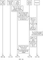
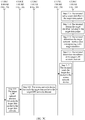
- FIG. 3A , FIG. 3B , and FIG. 3C are a flowchart of steps of an embodiment of a data routing method according to the present invention.
- Step 301 An AMF network element configures a terminal route selection policy list.
- the URSP list may include a traffic filter (Traffic filter), and the traffic filter is a data stream filtering condition, and a data stream that meets the data stream filtering condition needs to use the URSP list.
- the traffic filter in this embodiment may be a name of an application program.
- the URSP list may further include non-seamless offload (Non-seamless offload), and the non-seamless offload is used to indicate whether a data stream that meets the traffic filter filtering condition can be offloaded to a non-3GPP network for access.
- the non-3GPP access may be wireless-fidelity (wireless-fidelity, Wi-Fi) access.
- the non-seamless offload in this embodiment may include the following three values.
- Preferred Preferred
- Preferred is used to indicate that data traffic is preferentially offloaded from 3GPP access to non-3GPP access.
- the URSP list may further include slice information (Slice Info), and the slice info is used to indicate a network slice to which a data stream that meets a filtering condition can be sent.
- slice info may include one or more pieces of network slice selection assistance information (single network slice selection assistance information, S-NSSAI). More specifically, the S-NSSAI is an identifier of a network slice.
- the slice info in this embodiment may include a plurality of pieces of S-NSSAI.
- the URSP list may further include a service continuity type (Continuity Types), and the continuity type is used to indicate a service and session continuity (service and session continuity, SSC) mode (Mode).
- the SSC mode is used to establish a session between the core network side and the terminal.
- the SSC mode is used to establish a PDU session between the core network side and the terminal.
- the URSP list may further include a data network name (data network name, DNN), and the DNN is used to indicate a DN to which a data stream that meets a filtering condition can be sent.
- the URSP list may include one or more DNNs.
- the URSP list may further include an access network type (Access Type), and the access type may be used to indicate 3GPP access and non-3GPP access.
- Access Type an access network type
- the access type may be used to indicate 3GPP access and non-3GPP access.
- Step 302 The AMF network element sends the terminal route selection policy list to the access network device.
- the AMF network element may add the URSP list to a registration accept (Registration Accept) message, so that the terminal obtains the URSP list by parsing the registration accept message when the AMF network element sends the registration accept message to the terminal.
- the AMF network element may add the URSP list to a configuration update command (Configuration Update Command) message, so that the terminal obtains the URSP list by parsing the configuration update command message when the AMF network element sends the configuration update command message to the terminal.
- Descriptions about sending, by the AMF, the URSP list in this embodiment is an optional example, and does not impose a limitation, provided that the AMF network element can send the URSP list to the terminal.
- Step 304 The terminal receives the terminal route selection policy list.
- Step 305 The terminal sends indication information to the access network device.
- Step 306 The access network device forwards the indication information to the AMF network element.
- the indication information in this embodiment is used to request an address of a target network element from the AMF network element.
- the target network element is configured to forward a data packet sent by a target application program to a target data network configured to process the target data packet.
- the target data network implements a function corresponding to a target slice.
- the target data network may be an IP multimedia subsystem (IP multimedia subsystem, IMS) run by an operator, to support fixed access and mobile access.
- IP multimedia subsystem IP multimedia subsystem, IMS
- the target network element is a forwarding device that forwards related data to the target data network, for example, may be a UPF network element.
- the target application program is any application program installed on the terminal.
- the terminal may parse the URSP list.
- This embodiment uses the URSP list received by the terminal shown in Table 1 an example.
- Table 1 Rule ID Rule content 0 Traffic filter com.example.app0 Non-seamless offload Prohibited Slice info Slice 0 Continuity types SSC mode 3 DNN DNN 0 Access type 3GPP 1 Traffic filter com.example.app1 Non-seamless offload Prohibited Slice info Slice 0 Continuity types SSC mode 3 DNN DNN 1 Access type 3GPP 2 Traffic filter com.example.app2 Non-seamless offload Prohibited Slice info Slice 1 Continuity types SSC mode 3 DNN DNN 0 Access type 3GPP
- the URSP list includes correspondences between different IDs and different list content, and the list content includes but is not limited to Traffic filter, Non-seamless offload, Slice Info, Continuity Types, DNN, and Access Type.
- the list content includes but is not limited to Traffic filter, Non-seamless offload, Slice Info, Continuity Types, DNN, and Access Type.
- the terminal may first obtain a name of the target application program. If the terminal determines that the name of the target application program is com.example.app0, the terminal may determine, based on the URSP list, slice info corresponding to the name of the target application program.
- the slice info may include at least one network slice. If the slice info includes a plurality of network slices, because the target application program of the terminal needs to access only one DN in one network slice, the terminal may select one network slice from the plurality of network slices included in the slice info.
- the terminal may select, based on a priority sequence of the plurality of network slices included in the slice Info, a network slice with a highest priority as a target network slice.
- a priority sequence of the plurality of network slices included in the slice Info uses an example in which an identifier of the target network slice selected by the terminal is a slice 0.
- priorities of the plurality of network slices are sequenced based on the URSP list. To be specific, in the plurality of network slices included in the URSP list, a network slice ranked first has a highest priority, and a network slice ranked last has a lowest priority, or vice versa.
- a specific sequencing manner is not limited in this embodiment.
- the terminal may further determine, based on the URSP list, a target DNN corresponding to the name of the target application program.
- a target DN having the target DNN is used to serve the target application program, in other words, the target DN is used to process a data packet sent by the target application program.
- the URSP list may include at least one DNN If the URSP list includes a plurality of DNNs, the terminal may select one DNN from the plurality of DNNs included in the URSP list as the target DNN. Optionally, the terminal may select, based on a priority sequence of the plurality of DNNs included in the URSP list, a DNN with a highest priority as the target DNN.
- This embodiment uses an example in which the target DNN selected by the terminal is a DNN 0. Specifically, priorities of the plurality of DNNs are sequenced based on the URSP list. To be specific, in the plurality of DNNs included in the URSP list, a DNN ranked first has a highest priority, and a DNN ranked last has a lowest priority, or vice versa. A specific sequencing manner is not limited in this embodiment.
- the terminal may establish a correspondence shown in Table 2.
- the correspondence shown in Table 2 is a correspondence among the name of the target application program, an identifier of the target network slice, and the target DNN Table 2 Target app name Identifier of target network slice Target DNN com.example.app0 Slice 0 DNN 0 com.example.app 1 Slice 0 DNN 1 com.example.app2 Slice 1 DNN 0
- the terminal may generate the indication information based on the determined correspondence shown in Table 2. Specifically, the indication information includes a name of the target DN. In other words, the indication information includes the target DNN. It can be learned that in this embodiment, the terminal indicates, to the AMF network element by using the indication information including the target DNN, a service type of a session service initiated by the target application program.
- the AMF network element can determine, based on the received indication information, the target DN that is selected by the terminal and that has the target DNN
- the indication information may further include S-NSSAI corresponding to the name of the target application program and information used to establish a connection between the terminal and the target DN.
- Step 307 The AMF network element receives the indication information.
- the AMF network element may establish a connection relationship between the terminal and the target DN based on the indication information, so that the target DN can serve the target application program on the terminal based on a supported service type.
- Step 308 The AMF network element sends a response message to the access network device.
- Step 309 The access network device forwards the response message to the terminal.
- the AMF network element may send the response message to the terminal, and the response message includes an address of the target network element corresponding to the target DN.
- the address of the target network element in this embodiment may be an internet protocol (internet protocol, IP) address of the target network element.
- IP internet protocol
- the target network element is not limited in this embodiment, provided that the target network element can forward the target data packet of the target application program to the target DN. This embodiment uses an example in which the target network element is a target UPF network element for description.
- Step 310 The terminal determines the target network interface card corresponding to the address of the target UPF network element.
- the network interface card is a functional entity built in the terminal.
- the virtual network interface card is a virtual interface that connects a transmission control protocol/internet protocol (transmission control protocol/internet protocol, TCP/IP) stack and a modem (Modem), and each PDU session initiated by the terminal corresponds to one network interface card.
- the network interface card is a driver.
- the target network interface card determined by the terminal is configured to transmit data to the corresponding target UPF network element.
- the terminal may create the target network interface card corresponding to the target UPF network element, and then the terminal may create a correspondence listed in Table 3.
- the correspondence listed in Table 3 includes a correspondence among the identifier of the target network slice, the target DNN, an identifier of the target network interface card, and an identifier of the target UPF network element that correspond to the name of the target application program.
- Table 3 Target network slice Target DNN Identifier of target NIC Identifier of target UPF network element Slice 0 DNN 0 NIC0-0 GateWay0-0 Slice 0 DNN 1 NIC0-1 GateWay0-1 Slice 1 DNN 0 NIC1-0 GateWay 1-0
- the terminal establishes a correspondence between any target application program installed on the terminal and the identifier of the target network slice, the identifier of the target NIC, and the identifier of the target UPF network element shown in Table 3.
- the terminal may determine the target network interface card corresponding to the target UPF network element, and may further create a correspondence between the identifier of the target UPF network element such as "GateWay0-0" and the identifier of the target network interface card such as "NIC0-0" shown in Table 3.
- Step 311 The terminal creates a target routing table.
- the terminal creates an identifier corresponding to the target application program.
- the identifier is not limited in this embodiment, provided that the identifier corresponds to the target application program. It can be learned that, by using the method in this embodiment, a unique correspondence between the identifier and any application program installed on the terminal can be created.
- the identifier corresponding to the target application program is not limited in this embodiment.
- the target identifier may be any character. To be specific, the identifier in this embodiment may be any letter, digit, character, or symbol, provided that the target identifier corresponds to the target application program.
- the target routing table includes a correspondence between the target network interface card and the target UPF network element.
- the target routing table in this embodiment includes the correspondence between the identifier of the target network interface card and the identifier of the target UPF network element. It can be learned that, in step 311 in this embodiment, the terminal may create a plurality of routing tables, and different routing tables correspond to different application programs installed on the terminal.
- Step 312 The terminal receives the target data packet sent by the target application program.
- the target application program when the target application program installed on the terminal runs, the target application program may generate the target data packet.
- the target application program is WeChat installed on the terminal, the target data packet may be information sent by WeChat.
- the target application program is an email application program installed on the terminal, the target data packet may be an email sent by the email application program, or the like. Details are not described in this embodiment.
- Step 313 The terminal sets the target identifier in a descriptor of the target data packet.
- the terminal may determine the target routing table corresponding to the target application program, and then the terminal may set the target identifier in the descriptor of the target data packet based on the target identifier corresponding to the target application program and the target routing table.
- Step 301 to step 313 in this embodiment are preprocessing before routing.
- the terminal may set the target identifier in the descriptor of the target data packet. Steps below describe the following process in detail: After receiving the target data packet sent by the target application program, the terminal routes the target data packet based on the target identifier, to send the target data packet to the target DN that can process the target data packet.
- Step 314 The terminal obtains the target identifier included in the target data packet.
- the terminal may extract the target identifier from the descriptor of the target data packet.
- Step 315 The terminal determines the target network interface card corresponding to the target identifier.
- the terminal may determine the target routing table corresponding to the target identifier, and then the terminal may determine the target network interface card included in the target routing table.
- the target routing table includes the identifier of the target network interface card, so that the terminal determines the target network interface card based on the identifier of the target network interface card.
- a specific process in which the terminal determines the target routing table corresponding to the target identifier may be as follows: If different routing tables created by the terminal have different sequence numbers, the terminal may create correspondences between sequence numbers of different routing tables and different identifiers. In this case, when the terminal determines the target identifier, the terminal may determine a target sequence number corresponding to the target identifier, and the terminal may determine that a routing table with the target sequence number is the target routing table.
- a specific process in which the terminal determines the target routing table corresponding to the target identifier may be as follows: Different routing tables created by the terminal include identifiers corresponding to different application programs. In this case, when the terminal determines the target identifier, the terminal may determine that a routing table including the target identifier is the target routing table.
- Step 316 The terminal determines the address of the target UPF network element.
- the terminal determines, based on the target routing table, the address of the target UPF network element corresponding to the target network interface card. Specifically, if the target routing table includes the identifier of the target UPF network element, when the terminal determines the target routing table, the terminal may determine the target UPF network element based on the identifier of the target UPF network element included in the target routing table, so that the terminal determines the address of the target UPF network element.
- Step 317 The terminal sends the target data packet to the access network device.
- Step 318 The access network device forwards the target data packet to the target UPF network element. Specifically, the terminal may send the target data packet to the target UPF network element based on the address of the target UPF network element by using the target network interface card of the terminal.
- the target UPF network element forwards the target data packet to the target data network. Specifically, after receiving the target data packet, the target UPF network element may forward the target data packet to the target DN, so that the target DN can correspondingly process the target data packet, and the target DN can serve the target application program.
- the method in this embodiment is implemented based on a driver of the terminal.
- the terminal may determine a target routing table corresponding to any target application program run by the terminal.
- the terminal may determine, based on the target routing table, a path on which the target data packet of the target application program is sent, to accurately send the target data packet of the target application program to the DN that can serve the target application program.
- a complex change to code of the target application program is not needed, and modification in code of a core library of an operating system is also avoided, in other words, an application program manufacturer can send a data packet of an application program to a corresponding DNN without making a change to the application program, effectively ensuring that the data packet is successfully sent.
- FIG. 4A , FIG. 4B , and FIG. 4C are a schematic diagram of steps of an application scenario of a data routing method according to the present invention.
- a terminal route selection policy list can be applied to an Android (Android) system run on a terminal, to route an uplink data packet. Details are as follows.
- step 401 to step 410 in this application scenario For a specific execution process of step 401 to step 410 in this application scenario, refer to step 301 to step 310 shown in FIG. 3A , FIG. 3B , and FIG. 3C . Details are not described in this application scenario.
- this application scenario is described by using an example in which a PDU session may be established between the terminal and the target DN.
- Step 411 The terminal creates a target routing table (as shown in the following Table 7 to Table 9).
- the terminal may pre-parse a /data/system/packages.xml file in an Android system to establish a relationship shown in Table 4.
- Table 4 Target app name Target UID com.example.app0 1000 com.example.app1 1001 com.example.app2 1002
- Android is a Linux-based free and open-source operating system.
- a UID in a Linux system is used to support a plurality of users, and the Android system uses a UID to identify an application program. Android can be considered as a driver.
- the Android system allocates a UID to each application program when installing the application program. If the application program is not reinstalled, a UID corresponding to the application program does not change on the terminal. /data/system/packages.xml in the Android system records information about all application programs installed in the Android system. A corresponding UID may be found based on a name of an application program. In other words, a name of an application program and a UID are in a one-to-one correspondence. In this application scenario, Android application programs released by Android application program vendors are named based on company domain names, and do not conflict.
- the terminal may create the correspondence shown in Table 4 based on names of the application programs and corresponding UIDs. As shown in Table 4, for example, if the name of the target application program is "com.example.app0", a corresponding target UID is "1000".
- the terminal may combine Table 2, Table 3, and Table 4 shown in the foregoing embodiment, to establish a correspondence shown in Table 5.
- Table 5 Target UID Identifier of target NIC Identifier of target UPF network element 1000 NIC0-0 GateWay0-0 1001 NICO-1 GateWay0-1 1002 NIC1-0 GateWay 1-0
- the terminal may configure a corresponding identifier for any UID included in Table 5.
- the terminal shown in this application scenario may create, based on the correspondence shown in Table 5, a correspondence shown in Table 6 for the target UID "1000".
- the terminal creates a correspondence between the target user identifier UID and the target identifier based on the correspondence shown in Table 6.
- the target identifier is usually shorter than the target user identifier, to reduce table lookup difficulty. It can be learned from the correspondence shown in Table 6 that if the target UID corresponding to the name of the target application program is "1000", a corresponding target identifier is "10". It can be further learned that the terminal shown in this application scenario may create a routing table shown in Table 7. Table 7 Target sequence number Identifier of target NIC Identifier of target UPF network element 40 NIC0-0 GateWay0-0
- the terminal may further create a routing table shown in Table 8.
- Table 8 Target sequence number Identifier of target NIC Identifier of target UPF network element 50 NIC0-1 GateWay0-1
- the terminal may further create a routing table shown in Table 9.
- Table 9 Target sequence number Identifier of target NIC Identifier of target UPF network element 60 NIC1-0 GateWay 1-0
- the terminal creates a correspondence among a target sequence number, an identifier of a target NIC, and an identifier of a target UPF network element that are included in the routing table.
- a correspondence between any application program installed on the terminal and a routing table may be created.
- the terminal may store a plurality of routing tables, or a plurality of tables may be summarized into one summary table.
- the terminal may create the routing table shown in Table 7 by using an IP route (route) command in Linux.
- the IP route command is a command used by Linux to set a route, and the terminal may create the routing table by using the IP route command. More specifically, a command for the terminal to create the routing table may be as follows: NIC0-0:IP route add default via GateWay0-0 dev NIC 0-0 table 40.
- This command means that the terminal adds a routing table by using an IP route command.
- the routing table includes a correspondence among a target sequence number "40", an identifier "GateWay0-0" of the target UPF network element, and an identifier "NIC0-0" of the target network interface card.
- the command for the terminal to create the routing table may be as follows: NIC0-1:IP route add default via GateWay0-1 dev NICO-1 table 50.
- This command means that the terminal adds a routing table by using an IP route command.
- the routing table includes a correspondence among a target sequence number "50", an identifier "GateWayO-1" of the target UPF network element, and an identifier "NICO-1" of the target network interface card.
- the command for the terminal to create the routing table may be as follows: NIC1-0:IP route add default via GateWay1-0 dev NIC1-0 table 60.
- This command means that the terminal adds a routing table by using an IP route command.
- the routing table includes a correspondence among a target sequence number "60", an identifier "GateWayO-1" of the target UPF network element, and an identifier "NICO-1" of the target network interface card.
- Step 412 The terminal receives the target data packet sent by the target application program.
- the following describes an example of a transmission path, inside the terminal, of an uplink target data packet sent by a target application program 501 run on the terminal.
- a target data packet sent by the target application program 501 is transmitted to a protocol stack 502 on the local terminal.
- the protocol stack 502 may receive the target data packet sent by the target application program.
- Step 413 The terminal sets a target identifier in the target data packet.
- the protocol stack 502 may send the target data packet to an output chain (OUTPUT Chain) 503.
- a network filter (Netfilter) included in an Android system of the terminal is a part of a kernel, and includes some data packet filter tables. These tables include a rule set used by the kernel to control data packet filtering processing.
- the terminal inserts, modifies, or deletes a data packet filtering rule into a Netfilter filter table by using a tool named IP tables (tables) included in the Android system.
- IP tables tables
- Netfilter supports four tables and five chains.
- Netfilter supports a filter table (filter table), a network address translation (network address translation, NAT) table (table) 602, a mangle table (mangle table) 603, and a raw (raw) table 604.
- the four tables may be included in driver software such as Android.
- the filter table 601 is used to implement packet filtering
- the NAT table 602 is used to implement network address translation
- the mangle table 603 is used to implement packet reconstruction
- the raw table 604 is used to implement data tracking processing.
- the filter table 601 includes three chains: an input chain (INPUT Chain), a forward chain (FORWARD Chain), and an output chain (OUTPUT Chain).
- the NAT table 602 includes three chains: a prerouting rule chain (PREROUTING Chain), a postrouting rule chain (POSTROUTING Chain), and an OUTPUT chain.
- the mangle table 603 includes five chains: a PREROUTING chain, a POSTROUTING chain, an INPUT chain, an OUTPUT chain, and a FORWARD chain.
- the raw table 604 includes two chains: a PREROUTING chain and an OUTPUT chain.
- a plurality of rules may be mounted on the five chains of Netfilter, so that each chain processes, according to the mounted rules, a data packet that flows through the chain.
- the OUTPUT chain 503 may perform preset processing on the target data packet according to a pre-mounted rule.
- the preset processing in this embodiment is:
- the OUTPUT chain 503 included in the mangle table 603 determines the target identifier corresponding to the target application program, and sets the target identifier in a descriptor of the target data packet.
- the IP tables of the terminal have a UID option, and a preset rule is added, by using the UID option, to the OUTPUT chain 503 included in the mangle table 603, so that the OUTPUT chain 503 included in the mangle table 603 can perform the preset processing on the target data packet.
- the descriptor of the target data packet includes a target field, and the target field is specially used to record a marked value.
- the OUTPUT chain 503 may record the target identifier in the target field.
- a command used by the terminal to set the target identifier in the target data packet may be as follows: IPtables -t mangle -A OUTPUT -m owner --uid-owner 1000 -j MARK --setmark 10.
- the target identifier is usually shorter than the target user identifier, to reduce table lookup difficulty, so that this embodiment is more earlier to implement.
- the target identifier is used to identify the target routing table or the identifier of the target network interface card used by the application program, and is used for a routing operation in this embodiment. This is convenient and simple.
- the terminal may determine, based on the correspondence shown in Table 4, the target UID "1000" corresponding to the name "com.example.app0" of the target application program, and the terminal may further determine the target identifier "10" based on the correspondence shown in Table 6. In this case, the terminal may set the target identifier "10" in the descriptor of the target data packet.
- the command used by the terminal to set the target identifier in the target data packet may be as follows: IPtables -t mangle -A OUTPUT -m owner --uid-owner 1001 -j MARK --setmark 20.
- the command means that the terminal sets a target identifier "20" in a descriptor of a target data packet with a target UID "1001".
- the terminal may determine, based on the correspondence shown in Table 4, the target UID "1001" corresponding to the name "com.example.appl” of the target application program, and the terminal may further determine the target identifier "20" based on the correspondence shown in Table 6. In this case, the terminal may set the target identifier "20" in the descriptor of the target data packet.
- the command used by the terminal to set the target identifier in the target data packet may be as follows: IPtables -t mangle -A OUTPUT -m owner --uid-owner 1002 -j MARK --setmark 30.
- the command means that the terminal sets a target identifier "30" in a descriptor of a target data packet with a target UID "1002".
- the terminal may determine, based on the correspondence shown in Table 4, the target UID "1002" corresponding to the name "com.example.app2" of the target application program, and the terminal may further determine the target identifier "30" based on the correspondence shown in Table 6. In this case, the terminal may set the target identifier "30" in the descriptor of the target data packet.
- a command for setting the target identifier is not limited in this application scenario, provided that the terminal can set the target identifier in the target data packet.
- the terminal may perform processing at a routing Routing 504 on the target data packet.
- the protocol stack 502, the output chain 503, and the routing 504 may be included in driver software, for example, Android.
- the foregoing step 401 to step 413 are pre-processing before routing.
- the terminal may set the target identifier in the descriptor of the target data packet, to facilitate subsequent routing table lookup and simplify operation difficulty.
- the target identifier is used to identify the target routing table or the identifier of the target network interface card used by the application program, and is used for a routing operation in this embodiment. This is convenient and simple.
- Step 414 The terminal obtains the target identifier included in the target data packet.
- the terminal in this application scenario may obtain the target identifier that is set by the OUTPUT chain 503 in the descriptor of the target data packet.
- the target identifier For specific descriptions of the target identifier, refer to the foregoing descriptions.
- the terminal may determine the target routing table used to route the target data packet, so that the terminal can send the target data packet to the target DN based on the target routing table.
- the terminal stores a plurality of routing tables.
- the following describes how the routing 504 determines, from the plurality of routing tables (as shown in Table 7 to Table 9), the target routing table used to route the target data packet.
- the Android system may allocate a corresponding UID to each application program installed on the terminal, so that a data packet sent by any application program run on the terminal carries a UID corresponding to the application program.
- the routing 504 may obtain the target UID included in the target data packet.
- the routing 504 may obtain a prestored correspondence shown in Table 10.
- Table 10 Target identifier Target sequence number 10 40 20 50 30 60
- this application scenario is described by using an example in which target identifiers and target sequence numbers that correspond to each other are equal.
- target identifiers and target sequence numbers that correspond to each other may also be the same. This is not specifically limited in this application scenario, provided that the terminal can create correspondences between different target identifiers and sequence numbers of different routing tables.
- the routing 504 may determine, based on the correspondence shown in Table 10, that the target sequence number is "40". In this case, the routing 504 may determine that a routing table with the target sequence number "40" is the target routing table used to route the target data packet.
- the target routing table is that shown in Table 7.
- a command for the routing 504 to determine the target routing table may be as follows: IP rule add fwmark 10 table 40.
- This command means that any target data packet with the target identifier "10" is routed based on a routing table with the target sequence number "40".
- the command for the routing 504 to determine the target routing table may be as follows: IP rule add fwmark 20 table 20.
- This command means that any target data packet with the target identifier "20" is routed based on a routing table with the target sequence number "20".
- the command for the routing 504 to determine the target routing table may be as follows: IP rule add fwmark 30 table 60.
- This command means that any target data packet with the target identifier "30" is routed based on a routing table with the target sequence number "60".
- Step 415 The terminal determines the target network interface card corresponding to the target identifier. Specifically, when the terminal determines the target routing table, the terminal may determine the identifier of the target network interface card included in the target routing table, and further determine the target network interface card. In this application scenario, an example in which the target routing table is the routing table shown in Table 7 is used. In this case, the terminal determines that the identifier of the target network interface card is "NIC0-0", so that the terminal determines that the target network interface card is a network interface card with the identifier "NIC0-0".
- step 316 For a specific execution process of step 416 to step 419 shown in this application scenario, refer to step 316 to step 319 in the embodiment shown in FIG. 3A , FIG. 3B , and FIG. 3C . Details are not described.
- the method in the embodiment corresponding to FIG. 3A , FIG. 3B , and FIG. 3C or FIG. 4A , FIG. 4B , and FIG. 4C may be implemented by a processor by executing a software program.
- the software program for implementing a related function may be a driver different from an application program.
- the driver may include various modules mentioned in the foregoing embodiments, such as a network interface card or various tables mentioned above, to implement a routing operation.
- the driver is specifically an Android program involved in FIG. 4A , FIG. 4B , and FIG. 4C .
- the driver may enable an open source program or a closed source program to implement the method in the foregoing embodiment, to route a data packet corresponding to an application program or another program to the target data network.
- FIG. 7 the following describes a specific structure of the terminal by using an example from a perspective of physical hardware.
- FIG. 7 is a schematic structural diagram of an embodiment of a terminal according to the present invention.
- the terminal includes components such as an input unit 705, a processor 703, an output unit 701, a communications unit 707, a memory 704, and a power supply 709.
- the structure may be a bus structure or a star structure, and may include more or fewer parts than those shown in the figure, or combine some parts, or have different part arrangements.
- the output unit 701 is configured to output a to-be-displayed image.
- the image output unit 701 is configured to output text, a picture, and/or a video.
- the output unit 701 may include a display panel, such as a liquid crystal display (liquid crystal display, LCD), an organic light-emitting diode (organic light-emitting diode, OLED), or a field emission display (field emission display, FED).
- a display panel such as a liquid crystal display (liquid crystal display, LCD), an organic light-emitting diode (organic light-emitting diode, OLED), or a field emission display (field emission display, FED).
- the processor 703 is a control center of the terminal, and is connected to all parts of the entire terminal by using various interfaces and lines.
- the processor 703 runs or performs a software program and/or a module stored in the memory and invokes data stored in the memory, to implement various functions of the terminal and/or process data.
- the processor 703 may include an integrated circuit (Integrated Circuit, IC), for example, may include a single packaged IC, or may include a plurality of connected packaged ICs with a same function or different functions.
- IC integrated circuit
- the processor 703 may include a central processing unit (central processing Unit, CPU), or may include a combination of a graphics processing unit (graphics processing unit, GPU), a digital signal processor (digital signal processor, DSP), and a control chip (for example, a baseband chip) in a communications unit.
- CPU central processing Unit
- the CPU may be a single computing core, or may include a plurality of computing cores.
- the memory 704 is configured to store code and data, and the code is run by the processor 703.
- the memory 704 may be configured to store a software program and a module.
- the processor 703 runs the software program and the module that are stored in the memory 704, to execute various function applications of the terminal and implement data processing, which specifically includes method procedures in the foregoing embodiments.
- the memory 704 mainly includes a program storage area and a data storage area.
- the program storage area may store an operating system and an application program, such as a sound playback program or an image play program, required by at least one function.
- the data storage area may store data (such as audio data and a phone book) and the like that are created based on usage of the terminal.
- the application programs are used as an example for description.
- an application program in an actual product may also be another software program, for example, a software program run on a device other than a CPU.
- the software program may be a communications software program, an audio software program, a video software program, an artificial intelligence software program, or a power consumption management software program.
- the input unit 705 is configured to implement interaction between a user and the terminal and/or input information to the terminal.
- the input unit 705 may receive digit or character information entered by a user, to generate signal input related to a user setting or function control.
- the input unit 705 may be a touchscreen, or may be another man-machine interface such as a physical input key or a microphone, or may be another external information obtaining apparatus such as a camera.
- the communications unit 707 is configured to establish a communications channel, so that the terminal is connected to a remote server by using the communications channel and downloads media data from the remote server.
- the communications unit 707 may include a communications module such as a wireless local area network (wireless local area network, wireless LAN) module, a Bluetooth module, or a baseband module, and a radio frequency (radio frequency, RF) circuit corresponding to the communications module, configured to perform wireless local area network communication, Bluetooth communication, infrared communication, and/or cellular communications system communication.
- the communications unit 707 may include a baseband unit and a radio frequency unit.
- the power supply 709 is configured to supply power to different parts of the terminal to keep the terminal running.
- the power supply 709 may be a built-in battery, such as a common lithium-ion battery or a NiMH battery, or may include an external power supply that directly supplies power to the terminal, such as an AC adapter.
- the power supply 709 may further have a wider definition.
- the power supply 709 may further include a power management system, a charging system, a power fault detection circuit, a power converter or inverter, a power status indicator (such as a light emitting diode), and any other components that are related to power generation, management, and distribution of the terminal.
- An embodiment of the present invention further provides a computer-readable storage medium.
- the computer-readable storage medium includes an instruction.
- the instruction When the instruction is run on a terminal or a processor, the terminal or the processor is enabled to perform the data routing method in the foregoing embodiments.
- the terminal or the processor For a specific execution process of the data routing method, refer to the foregoing descriptions. Details are not described again.
- An embodiment of the present invention further provides a computer program product including an instruction.
- the computer program product is a driver run on a terminal system.
- the computer program product used as a driver is a program that can enable a terminal to communicate with a target network element.
- the terminal or the processor is enabled to perform the data routing method in the foregoing embodiments. For a specific execution process of the data routing method, refer to the foregoing descriptions. Details are not described again.
- the data routing apparatus is configured to perform the data routing method in the foregoing embodiments.
- the data routing apparatus specifically includes:
- the data routing apparatus may determine a target routing table corresponding to any target application program run by the terminal. In this case, the data routing apparatus may determine, based on the target routing table, a path on which the target data packet of the target application program is sent, to accurately send the target data packet of the target application program to the DN that can serve the target application program.
- a complex change to code of the target application program is not needed, and modification in code of a core library of an operating system is also avoided, in other words, an application program manufacturer can send a data packet of an application program to a corresponding DNN without making a change to the application program, effectively ensuring that the data packet is successfully sent.
- the disclosed system, apparatus, and method may be implemented in another manner.
- the described apparatus embodiments are merely examples.
- the unit division is merely logical function division and may be other division in actual implementation.
- a plurality of units or components may be combined or integrated into another system, or some features may be ignored or not performed.
- the displayed or discussed mutual coupling or a direct coupling or a communication connection may be implemented by using some interfaces.
- An indirect coupling or a communication connection between the apparatuses or units may be implemented in an electrical form, a mechanical form, or in another form.
- functional units in the embodiments of the present invention may be integrated into one processing unit, or each of the units may exist alone physically, or two or more units are integrated into one unit.
- the foregoing integrated units may be implemented in a form of hardware, or may be implemented in a form of a software functional unit.
- the integrated unit When the integrated unit is implemented in the form of the software functional unit and sold or used as an independent product, the integrated unit may be stored in a computer-readable storage medium. Based on such an understanding, the technical solutions of the present invention essentially, or the part contributing to the prior art, or all or some of the technical solutions may be implemented in the form of a software product.
- the computer software product is stored in a storage medium and includes several instructions for instructing a computer device (which may be a personal computer, a server, a network device, or the like) to perform all or some of the steps of the methods described in the embodiments of the present invention.
- the foregoing storage medium includes: any medium that can store program code, such as a USB flash drive, a removable hard disk, a read-only memory (ROM, Read-Only Memory), a random access memory (RAM, Random Access Memory), a magnetic disk, and an optical disc.
- program code such as a USB flash drive, a removable hard disk, a read-only memory (ROM, Read-Only Memory), a random access memory (RAM, Random Access Memory), a magnetic disk, and an optical disc.
Landscapes
- Engineering & Computer Science (AREA)
- Computer Networks & Wireless Communication (AREA)
- Signal Processing (AREA)
- Computer Security & Cryptography (AREA)
- Data Exchanges In Wide-Area Networks (AREA)
Applications Claiming Priority (2)
| Application Number | Priority Date | Filing Date | Title |
|---|---|---|---|
| CN201711475083.XA CN109996307B (zh) | 2017-12-29 | 2017-12-29 | 一种数据路由方法以及终端 |
| PCT/CN2018/099125 WO2019128240A1 (fr) | 2017-12-29 | 2018-08-07 | Procédé d'acheminement de données et terminal |
Publications (3)
| Publication Number | Publication Date |
|---|---|
| EP3720189A1 true EP3720189A1 (fr) | 2020-10-07 |
| EP3720189A4 EP3720189A4 (fr) | 2020-10-28 |
| EP3720189B1 EP3720189B1 (fr) | 2024-03-20 |
Family
ID=67065017
Family Applications (1)
| Application Number | Title | Priority Date | Filing Date |
|---|---|---|---|
| EP18894023.3A Active EP3720189B1 (fr) | 2017-12-29 | 2018-08-07 | Procédé d'acheminement de données et terminal |
Country Status (4)
| Country | Link |
|---|---|
| US (1) | US11405844B2 (fr) |
| EP (1) | EP3720189B1 (fr) |
| CN (1) | CN109996307B (fr) |
| WO (1) | WO2019128240A1 (fr) |
Cited By (1)
| Publication number | Priority date | Publication date | Assignee | Title |
|---|---|---|---|---|
| CN116708043A (zh) * | 2023-08-08 | 2023-09-05 | 南京赛宁信息技术有限公司 | 一种网络靶场中用户流量追踪方法与系统 |
Families Citing this family (18)
| Publication number | Priority date | Publication date | Assignee | Title |
|---|---|---|---|---|
| US10841226B2 (en) * | 2019-03-29 | 2020-11-17 | Juniper Networks, Inc. | Configuring service load balancers with specified backend virtual networks |
| EP4024783A4 (fr) * | 2019-09-11 | 2022-09-07 | Huawei Technologies Co., Ltd. | Procédé et appareil de commande destinés à la transmission de données |
| CN111405682B (zh) * | 2020-03-19 | 2024-04-16 | 中国联合网络通信集团有限公司 | 一种数据转发方法及网关 |
| CN113541989B (zh) * | 2020-04-17 | 2023-05-09 | 中国移动通信有限公司研究院 | 一种网络切片检测方法、装置和存储介质 |
| CN111858053B (zh) * | 2020-07-22 | 2023-01-10 | 苏州浪潮智能科技有限公司 | 一种fpga资源的动态均衡方法、装置和介质 |
| CN114258089B (zh) * | 2020-09-23 | 2025-12-19 | 中兴通讯股份有限公司 | 网络切片的选择方法、装置及终端、计算机可读存储介质 |
| CN114339798A (zh) * | 2020-09-25 | 2022-04-12 | 中国移动通信有限公司研究院 | 切片映射方法、装置、终端及存储介质 |
| CN112217682B (zh) * | 2020-10-26 | 2022-12-06 | 高新兴物联科技股份有限公司 | 一种基于网络切片的无线通信方法及装置 |
| KR20230172598A (ko) | 2021-04-26 | 2023-12-22 | 후아웨이 테크놀러지 컴퍼니 리미티드 | 통신 방법 및 장치, 저장 매체, 및 칩 시스템 |
| CN115843073B (zh) * | 2021-09-13 | 2025-11-18 | 中国移动通信集团设计院有限公司 | 一种网络切片的选择方法、移动管理功能实体及终端 |
| CN115767691B (zh) * | 2021-12-02 | 2026-01-02 | 成都鼎桥通信技术有限公司 | 设备功耗的控制方法、装置、设备及存储介质 |
| CN114430391B (zh) * | 2021-12-23 | 2024-07-30 | 东莞市李群自动化技术有限公司 | 网络域创建的方法、网络系统、设备及存储介质 |
| CN114978911B (zh) * | 2022-05-20 | 2024-03-08 | 中国联合网络通信集团有限公司 | 网络切片的关联方法、设备主体、通信模组及终端设备 |
| WO2023228249A1 (fr) * | 2022-05-23 | 2023-11-30 | 楽天モバイル株式会社 | Système de commande de trajet de communication, terminal de communication, dispositif relais, procédé de commande de trajet de communication et programme |
| CN116488945B (zh) * | 2023-06-20 | 2023-09-15 | 杭州默安科技有限公司 | 一种容器网络隔离方法和系统 |
| US20250008313A1 (en) * | 2023-06-27 | 2025-01-02 | Verizon Patent And Licensing Inc. | System and method for network driven slice switching |
| WO2026033643A1 (fr) * | 2024-08-06 | 2026-02-12 | 京セラ株式会社 | Dispositif de gestion de tranche de réseau et procédé de gestion |
| WO2026033644A1 (fr) * | 2024-08-06 | 2026-02-12 | 京セラ株式会社 | Dispositif de gestion de tranche de réseau et procédé de gestion |
Family Cites Families (29)
| Publication number | Priority date | Publication date | Assignee | Title |
|---|---|---|---|---|
| JP4502002B2 (ja) * | 2007-12-21 | 2010-07-14 | 富士ゼロックス株式会社 | 情報利用制御システムおよび情報利用制御装置 |
| US7996484B2 (en) * | 2008-12-11 | 2011-08-09 | Microsoft Corporation | Non-disruptive, reliable live migration of virtual machines with network data reception directly into virtual machines' memory |
| WO2010113215A1 (fr) * | 2009-03-31 | 2010-10-07 | 富士通株式会社 | Dispositif de gestion d'informations pour identifiant unique, dispositif de traitement de l'information et procédé de fixation d'informations pour identifiant unique |
| CN102025598B (zh) * | 2009-09-17 | 2014-10-22 | 中兴通讯股份有限公司 | 接入路由器本地映射表更新方法及本地接入路由器 |
| CN101695160B (zh) | 2009-10-20 | 2012-05-23 | 清华大学 | 基于策略路由的流定向传输方法 |
| JP5776022B2 (ja) * | 2011-04-13 | 2015-09-09 | パナソニックIpマネジメント株式会社 | 制御装置 |
| CN102523276B (zh) * | 2011-12-09 | 2016-02-24 | 华为终端有限公司 | 一种管理移动宽带设备的方法、设备及系统 |
| CN103167483B (zh) * | 2011-12-15 | 2016-02-24 | 中国移动通信集团公司 | 一种基于隧道的数据转发方法、设备及系统 |
| WO2014044689A1 (fr) * | 2012-09-24 | 2014-03-27 | Telefonica, S.A. | Procédé de connexion de programmes et/ou d'applications à des interfaces réseau |
| WO2014073188A1 (fr) * | 2012-11-08 | 2014-05-15 | パナソニック株式会社 | Système de bus de circuit à semi-conducteur |
| US9386511B2 (en) * | 2013-02-25 | 2016-07-05 | Lg Electronics Inc. | Method and an apparatus for access network selection in visited network in a wireless communication system |
| CN104753791B (zh) * | 2013-12-31 | 2019-01-01 | 中国移动通信集团公司 | 一种数据包处理方法、装置和系统 |
| US9247397B2 (en) * | 2014-01-15 | 2016-01-26 | Abb Inc. | Distribution of multicast traffic through a mesh network |
| US9561469B2 (en) * | 2014-03-24 | 2017-02-07 | Johnson Matthey Public Limited Company | Catalyst for treating exhaust gas |
| CN105577502B (zh) * | 2014-10-17 | 2020-03-10 | 中兴通讯股份有限公司 | 业务传送方法及装置 |
| US9736063B2 (en) | 2015-02-17 | 2017-08-15 | Huawei Technologies Co., Ltd. | Service chaining using source routing |
| LU92843B1 (en) * | 2015-10-06 | 2017-05-02 | Univ Luxembourg | Network Management System |
| CN106572517B (zh) * | 2015-10-09 | 2018-12-18 | 中国移动通信集团公司 | 网络切片的处理方法、接入网络的选择方法及装置 |
| CN105721314A (zh) * | 2016-02-05 | 2016-06-29 | 华为技术有限公司 | 一种发送数据包的方法及设备 |
| CN107295609B (zh) * | 2016-03-30 | 2021-06-15 | 中兴通讯股份有限公司 | 网络切片处理方法及装置、终端、基站 |
| US10142994B2 (en) * | 2016-04-18 | 2018-11-27 | Electronics And Telecommunications Research Institute | Communication method and apparatus using network slicing |
| CN107318113B (zh) * | 2016-04-27 | 2021-09-21 | 华为技术有限公司 | 网络切片处理方法和装置 |
| US10362511B2 (en) * | 2016-05-17 | 2019-07-23 | Lg Electronics Inc. | Method and apparatus for determining PDU session identity in wireless communication system |
| CN112165725B (zh) | 2016-06-15 | 2024-03-19 | 华为技术有限公司 | 报文处理的方法及设备 |
| CN110771251B (zh) * | 2017-06-16 | 2023-09-22 | 艾普拉控股有限公司 | 作为通信网络中的服务的小数据传送、数据缓冲及数据管理 |
| EP3641424B1 (fr) * | 2017-06-17 | 2022-05-04 | LG Electronics Inc. | Procédé d'enregistrement d'un équipement d'utilisateur avec une tranche de réseau dans un système de communication sans fil et équipement d'utilisateur pour ce procédé |
| CN109257769B (zh) * | 2017-07-12 | 2020-09-01 | 维沃移动通信有限公司 | 一种处理网络切片拥塞的方法、相关设备和系统 |
| IL272552B2 (en) * | 2017-08-11 | 2023-09-01 | Idac Holdings Inc | Traffic routing and switching between multiple access networks |
| US10855814B2 (en) * | 2017-10-20 | 2020-12-01 | Comcast Cable Communications, Llc | Non-access stratum capability information |
-
2017
- 2017-12-29 CN CN201711475083.XA patent/CN109996307B/zh active Active
-
2018
- 2018-08-07 WO PCT/CN2018/099125 patent/WO2019128240A1/fr not_active Ceased
- 2018-08-07 EP EP18894023.3A patent/EP3720189B1/fr active Active
-
2020
- 2020-06-23 US US16/909,423 patent/US11405844B2/en active Active
Cited By (2)
| Publication number | Priority date | Publication date | Assignee | Title |
|---|---|---|---|---|
| CN116708043A (zh) * | 2023-08-08 | 2023-09-05 | 南京赛宁信息技术有限公司 | 一种网络靶场中用户流量追踪方法与系统 |
| CN116708043B (zh) * | 2023-08-08 | 2023-11-10 | 南京赛宁信息技术有限公司 | 一种网络靶场中用户流量追踪方法与系统 |
Also Published As
| Publication number | Publication date |
|---|---|
| EP3720189A4 (fr) | 2020-10-28 |
| EP3720189B1 (fr) | 2024-03-20 |
| CN109996307A (zh) | 2019-07-09 |
| WO2019128240A1 (fr) | 2019-07-04 |
| CN109996307B (zh) | 2021-06-01 |
| US11405844B2 (en) | 2022-08-02 |
| US20200322867A1 (en) | 2020-10-08 |
Similar Documents
| Publication | Publication Date | Title |
|---|---|---|
| US11405844B2 (en) | Data routing method and terminal | |
| US11902389B2 (en) | Mechanism to facilitate signaling traffic | |
| US11258667B2 (en) | Network management method and related device | |
| US10397120B2 (en) | Service link selection control method and device | |
| US10798646B2 (en) | Network slice determining method and system, and apparatus | |
| EP3512233B1 (fr) | Procédé de gestion de tranche de réseau et unité de gestion | |
| EP3735043B1 (fr) | Procédé et appareil de déploiement de tranche de réseau | |
| US20180210538A1 (en) | Power distribution unit self-identification | |
| CA3072674A1 (fr) | Methode de parametrage d'une unite de donnees du protocole, procede d'etablissement de politiques pour le materiel employe par l'utilisateuret entite associee | |
| US9264522B1 (en) | Ensuring communication device capabilities comply with content provider specifications | |
| CN114039930B (zh) | 数据包处理方法及系统 | |
| US11044729B2 (en) | Function scheduling method, device, and system | |
| US20220312309A1 (en) | Method and Apparatus for Reporting User Plane Function Information, Storage Medium, and Electronic Apparatus | |
| US12273938B2 (en) | System and method of managing PNF connectivity in a network slice instance | |
| CN103229489B (zh) | 虚拟机控制策略的配置方法和交换机 | |
| US11057820B2 (en) | Dynamic mapping of nodes responsible for monitoring traffic of an evolved packet core | |
| CN114302426A (zh) | 在异质网络控制服务质量的方法、装置、介质及电子设备 | |
| US9807819B1 (en) | Cross-technology session continuity | |
| WO2024120282A1 (fr) | Procédé d'envoi d'informations, procédé de réception d'informations, appareil, terminal et dispositif côté réseau | |
| CN117793850A (zh) | 网络接入方法、终端、系统、电子设备及存储介质 | |
| WO2021027474A1 (fr) | Procédé de diffusion d'informations d'aide au positionnement, serveur de positionnement et nœud de ran | |
| US11477719B1 (en) | Wireless communication service responsive to an artificial intelligence (AI) network | |
| WO2025172157A1 (fr) | Sélection de tranche initiée par réseau dans des réseaux de communication sans fil | |
| CN114363918A (zh) | 网络切片签约方法、用户设备、核心网设备及系统 | |
| CN114501493A (zh) | 网络切片更新方法及系统、存储介质及电子设备 |
Legal Events
| Date | Code | Title | Description |
|---|---|---|---|
| STAA | Information on the status of an ep patent application or granted ep patent |
Free format text: STATUS: THE INTERNATIONAL PUBLICATION HAS BEEN MADE |
|
| PUAI | Public reference made under article 153(3) epc to a published international application that has entered the european phase |
Free format text: ORIGINAL CODE: 0009012 |
|
| STAA | Information on the status of an ep patent application or granted ep patent |
Free format text: STATUS: REQUEST FOR EXAMINATION WAS MADE |
|
| 17P | Request for examination filed |
Effective date: 20200630 |
|
| AK | Designated contracting states |
Kind code of ref document: A1 Designated state(s): AL AT BE BG CH CY CZ DE DK EE ES FI FR GB GR HR HU IE IS IT LI LT LU LV MC MK MT NL NO PL PT RO RS SE SI SK SM TR |
|
| AX | Request for extension of the european patent |
Extension state: BA ME |
|
| A4 | Supplementary search report drawn up and despatched |
Effective date: 20200929 |
|
| RIC1 | Information provided on ipc code assigned before grant |
Ipc: H04W 40/02 20090101AFI20200923BHEP Ipc: H04W 40/24 20090101ALI20200923BHEP Ipc: H04W 48/18 20090101ALI20200923BHEP |
|
| DAV | Request for validation of the european patent (deleted) | ||
| DAX | Request for extension of the european patent (deleted) | ||
| STAA | Information on the status of an ep patent application or granted ep patent |
Free format text: STATUS: EXAMINATION IS IN PROGRESS |
|
| 17Q | First examination report despatched |
Effective date: 20221026 |
|
| REG | Reference to a national code |
Ref country code: DE Ref legal event code: R079 Free format text: PREVIOUS MAIN CLASS: H04W0040020000 Ipc: H04W0024020000 Ref country code: DE Ref legal event code: R079 Ref document number: 602018067015 Country of ref document: DE Free format text: PREVIOUS MAIN CLASS: H04W0040020000 Ipc: H04W0024020000 |
|
| RIC1 | Information provided on ipc code assigned before grant |
Ipc: H04W 40/24 20090101ALI20230918BHEP Ipc: H04W 40/02 20090101ALI20230918BHEP Ipc: H04W 24/02 20090101AFI20230918BHEP |
|
| GRAP | Despatch of communication of intention to grant a patent |
Free format text: ORIGINAL CODE: EPIDOSNIGR1 |
|
| STAA | Information on the status of an ep patent application or granted ep patent |
Free format text: STATUS: GRANT OF PATENT IS INTENDED |
|
| INTG | Intention to grant announced |
Effective date: 20231107 |
|
| GRAS | Grant fee paid |
Free format text: ORIGINAL CODE: EPIDOSNIGR3 |
|
| GRAA | (expected) grant |
Free format text: ORIGINAL CODE: 0009210 |
|
| STAA | Information on the status of an ep patent application or granted ep patent |
Free format text: STATUS: THE PATENT HAS BEEN GRANTED |
|
| AK | Designated contracting states |
Kind code of ref document: B1 Designated state(s): AL AT BE BG CH CY CZ DE DK EE ES FI FR GB GR HR HU IE IS IT LI LT LU LV MC MK MT NL NO PL PT RO RS SE SI SK SM TR |
|
| REG | Reference to a national code |
Ref country code: GB Ref legal event code: FG4D |
|
| REG | Reference to a national code |
Ref country code: CH Ref legal event code: EP |
|
| REG | Reference to a national code |
Ref country code: IE Ref legal event code: FG4D |
|
| REG | Reference to a national code |
Ref country code: DE Ref legal event code: R096 Ref document number: 602018067015 Country of ref document: DE |
|
| PG25 | Lapsed in a contracting state [announced via postgrant information from national office to epo] |
Ref country code: LT Free format text: LAPSE BECAUSE OF FAILURE TO SUBMIT A TRANSLATION OF THE DESCRIPTION OR TO PAY THE FEE WITHIN THE PRESCRIBED TIME-LIMIT Effective date: 20240320 |
|
| REG | Reference to a national code |
Ref country code: LT Ref legal event code: MG9D |
|
| PG25 | Lapsed in a contracting state [announced via postgrant information from national office to epo] |
Ref country code: GR Free format text: LAPSE BECAUSE OF FAILURE TO SUBMIT A TRANSLATION OF THE DESCRIPTION OR TO PAY THE FEE WITHIN THE PRESCRIBED TIME-LIMIT Effective date: 20240621 |
|
| PG25 | Lapsed in a contracting state [announced via postgrant information from national office to epo] |
Ref country code: HR Free format text: LAPSE BECAUSE OF FAILURE TO SUBMIT A TRANSLATION OF THE DESCRIPTION OR TO PAY THE FEE WITHIN THE PRESCRIBED TIME-LIMIT Effective date: 20240320 Ref country code: RS Free format text: LAPSE BECAUSE OF FAILURE TO SUBMIT A TRANSLATION OF THE DESCRIPTION OR TO PAY THE FEE WITHIN THE PRESCRIBED TIME-LIMIT Effective date: 20240620 |
|
| REG | Reference to a national code |
Ref country code: NL Ref legal event code: MP Effective date: 20240320 |
|
| PG25 | Lapsed in a contracting state [announced via postgrant information from national office to epo] |
Ref country code: RS Free format text: LAPSE BECAUSE OF FAILURE TO SUBMIT A TRANSLATION OF THE DESCRIPTION OR TO PAY THE FEE WITHIN THE PRESCRIBED TIME-LIMIT Effective date: 20240620 Ref country code: NO Free format text: LAPSE BECAUSE OF FAILURE TO SUBMIT A TRANSLATION OF THE DESCRIPTION OR TO PAY THE FEE WITHIN THE PRESCRIBED TIME-LIMIT Effective date: 20240620 Ref country code: LT Free format text: LAPSE BECAUSE OF FAILURE TO SUBMIT A TRANSLATION OF THE DESCRIPTION OR TO PAY THE FEE WITHIN THE PRESCRIBED TIME-LIMIT Effective date: 20240320 Ref country code: HR Free format text: LAPSE BECAUSE OF FAILURE TO SUBMIT A TRANSLATION OF THE DESCRIPTION OR TO PAY THE FEE WITHIN THE PRESCRIBED TIME-LIMIT Effective date: 20240320 Ref country code: GR Free format text: LAPSE BECAUSE OF FAILURE TO SUBMIT A TRANSLATION OF THE DESCRIPTION OR TO PAY THE FEE WITHIN THE PRESCRIBED TIME-LIMIT Effective date: 20240621 Ref country code: FI Free format text: LAPSE BECAUSE OF FAILURE TO SUBMIT A TRANSLATION OF THE DESCRIPTION OR TO PAY THE FEE WITHIN THE PRESCRIBED TIME-LIMIT Effective date: 20240320 Ref country code: BG Free format text: LAPSE BECAUSE OF FAILURE TO SUBMIT A TRANSLATION OF THE DESCRIPTION OR TO PAY THE FEE WITHIN THE PRESCRIBED TIME-LIMIT Effective date: 20240320 |
|
| REG | Reference to a national code |
Ref country code: AT Ref legal event code: MK05 Ref document number: 1668895 Country of ref document: AT Kind code of ref document: T Effective date: 20240320 |
|
| PG25 | Lapsed in a contracting state [announced via postgrant information from national office to epo] |
Ref country code: SE Free format text: LAPSE BECAUSE OF FAILURE TO SUBMIT A TRANSLATION OF THE DESCRIPTION OR TO PAY THE FEE WITHIN THE PRESCRIBED TIME-LIMIT Effective date: 20240320 Ref country code: LV Free format text: LAPSE BECAUSE OF FAILURE TO SUBMIT A TRANSLATION OF THE DESCRIPTION OR TO PAY THE FEE WITHIN THE PRESCRIBED TIME-LIMIT Effective date: 20240320 |
|
| PG25 | Lapsed in a contracting state [announced via postgrant information from national office to epo] |
Ref country code: NL Free format text: LAPSE BECAUSE OF FAILURE TO SUBMIT A TRANSLATION OF THE DESCRIPTION OR TO PAY THE FEE WITHIN THE PRESCRIBED TIME-LIMIT Effective date: 20240320 |
|
| PG25 | Lapsed in a contracting state [announced via postgrant information from national office to epo] |
Ref country code: NL Free format text: LAPSE BECAUSE OF FAILURE TO SUBMIT A TRANSLATION OF THE DESCRIPTION OR TO PAY THE FEE WITHIN THE PRESCRIBED TIME-LIMIT Effective date: 20240320 |
|
| PG25 | Lapsed in a contracting state [announced via postgrant information from national office to epo] |
Ref country code: IS Free format text: LAPSE BECAUSE OF FAILURE TO SUBMIT A TRANSLATION OF THE DESCRIPTION OR TO PAY THE FEE WITHIN THE PRESCRIBED TIME-LIMIT Effective date: 20240720 |
|
| PG25 | Lapsed in a contracting state [announced via postgrant information from national office to epo] |
Ref country code: PT Free format text: LAPSE BECAUSE OF FAILURE TO SUBMIT A TRANSLATION OF THE DESCRIPTION OR TO PAY THE FEE WITHIN THE PRESCRIBED TIME-LIMIT Effective date: 20240722 Ref country code: SM Free format text: LAPSE BECAUSE OF FAILURE TO SUBMIT A TRANSLATION OF THE DESCRIPTION OR TO PAY THE FEE WITHIN THE PRESCRIBED TIME-LIMIT Effective date: 20240320 |
|
| PG25 | Lapsed in a contracting state [announced via postgrant information from national office to epo] |
Ref country code: ES Free format text: LAPSE BECAUSE OF FAILURE TO SUBMIT A TRANSLATION OF THE DESCRIPTION OR TO PAY THE FEE WITHIN THE PRESCRIBED TIME-LIMIT Effective date: 20240320 |
|
| PG25 | Lapsed in a contracting state [announced via postgrant information from national office to epo] |
Ref country code: CZ Free format text: LAPSE BECAUSE OF FAILURE TO SUBMIT A TRANSLATION OF THE DESCRIPTION OR TO PAY THE FEE WITHIN THE PRESCRIBED TIME-LIMIT Effective date: 20240320 Ref country code: EE Free format text: LAPSE BECAUSE OF FAILURE TO SUBMIT A TRANSLATION OF THE DESCRIPTION OR TO PAY THE FEE WITHIN THE PRESCRIBED TIME-LIMIT Effective date: 20240320 |
|
| PG25 | Lapsed in a contracting state [announced via postgrant information from national office to epo] |
Ref country code: AT Free format text: LAPSE BECAUSE OF FAILURE TO SUBMIT A TRANSLATION OF THE DESCRIPTION OR TO PAY THE FEE WITHIN THE PRESCRIBED TIME-LIMIT Effective date: 20240320 |
|
| PG25 | Lapsed in a contracting state [announced via postgrant information from national office to epo] |
Ref country code: PL Free format text: LAPSE BECAUSE OF FAILURE TO SUBMIT A TRANSLATION OF THE DESCRIPTION OR TO PAY THE FEE WITHIN THE PRESCRIBED TIME-LIMIT Effective date: 20240320 |
|
| PG25 | Lapsed in a contracting state [announced via postgrant information from national office to epo] |
Ref country code: SK Free format text: LAPSE BECAUSE OF FAILURE TO SUBMIT A TRANSLATION OF THE DESCRIPTION OR TO PAY THE FEE WITHIN THE PRESCRIBED TIME-LIMIT Effective date: 20240320 |
|
| PG25 | Lapsed in a contracting state [announced via postgrant information from national office to epo] |
Ref country code: SM Free format text: LAPSE BECAUSE OF FAILURE TO SUBMIT A TRANSLATION OF THE DESCRIPTION OR TO PAY THE FEE WITHIN THE PRESCRIBED TIME-LIMIT Effective date: 20240320 Ref country code: SK Free format text: LAPSE BECAUSE OF FAILURE TO SUBMIT A TRANSLATION OF THE DESCRIPTION OR TO PAY THE FEE WITHIN THE PRESCRIBED TIME-LIMIT Effective date: 20240320 Ref country code: RO Free format text: LAPSE BECAUSE OF FAILURE TO SUBMIT A TRANSLATION OF THE DESCRIPTION OR TO PAY THE FEE WITHIN THE PRESCRIBED TIME-LIMIT Effective date: 20240320 Ref country code: PT Free format text: LAPSE BECAUSE OF FAILURE TO SUBMIT A TRANSLATION OF THE DESCRIPTION OR TO PAY THE FEE WITHIN THE PRESCRIBED TIME-LIMIT Effective date: 20240722 Ref country code: PL Free format text: LAPSE BECAUSE OF FAILURE TO SUBMIT A TRANSLATION OF THE DESCRIPTION OR TO PAY THE FEE WITHIN THE PRESCRIBED TIME-LIMIT Effective date: 20240320 Ref country code: IS Free format text: LAPSE BECAUSE OF FAILURE TO SUBMIT A TRANSLATION OF THE DESCRIPTION OR TO PAY THE FEE WITHIN THE PRESCRIBED TIME-LIMIT Effective date: 20240720 Ref country code: ES Free format text: LAPSE BECAUSE OF FAILURE TO SUBMIT A TRANSLATION OF THE DESCRIPTION OR TO PAY THE FEE WITHIN THE PRESCRIBED TIME-LIMIT Effective date: 20240320 Ref country code: EE Free format text: LAPSE BECAUSE OF FAILURE TO SUBMIT A TRANSLATION OF THE DESCRIPTION OR TO PAY THE FEE WITHIN THE PRESCRIBED TIME-LIMIT Effective date: 20240320 Ref country code: CZ Free format text: LAPSE BECAUSE OF FAILURE TO SUBMIT A TRANSLATION OF THE DESCRIPTION OR TO PAY THE FEE WITHIN THE PRESCRIBED TIME-LIMIT Effective date: 20240320 Ref country code: AT Free format text: LAPSE BECAUSE OF FAILURE TO SUBMIT A TRANSLATION OF THE DESCRIPTION OR TO PAY THE FEE WITHIN THE PRESCRIBED TIME-LIMIT Effective date: 20240320 |
|
| PG25 | Lapsed in a contracting state [announced via postgrant information from national office to epo] |
Ref country code: IT Free format text: LAPSE BECAUSE OF FAILURE TO SUBMIT A TRANSLATION OF THE DESCRIPTION OR TO PAY THE FEE WITHIN THE PRESCRIBED TIME-LIMIT Effective date: 20240320 |
|
| REG | Reference to a national code |
Ref country code: DE Ref legal event code: R097 Ref document number: 602018067015 Country of ref document: DE |
|
| PG25 | Lapsed in a contracting state [announced via postgrant information from national office to epo] |
Ref country code: IT Free format text: LAPSE BECAUSE OF FAILURE TO SUBMIT A TRANSLATION OF THE DESCRIPTION OR TO PAY THE FEE WITHIN THE PRESCRIBED TIME-LIMIT Effective date: 20240320 |
|
| PG25 | Lapsed in a contracting state [announced via postgrant information from national office to epo] |
Ref country code: DK Free format text: LAPSE BECAUSE OF FAILURE TO SUBMIT A TRANSLATION OF THE DESCRIPTION OR TO PAY THE FEE WITHIN THE PRESCRIBED TIME-LIMIT Effective date: 20240320 |
|
| PLBE | No opposition filed within time limit |
Free format text: ORIGINAL CODE: 0009261 |
|
| STAA | Information on the status of an ep patent application or granted ep patent |
Free format text: STATUS: NO OPPOSITION FILED WITHIN TIME LIMIT |
|
| PG25 | Lapsed in a contracting state [announced via postgrant information from national office to epo] |
Ref country code: DK Free format text: LAPSE BECAUSE OF FAILURE TO SUBMIT A TRANSLATION OF THE DESCRIPTION OR TO PAY THE FEE WITHIN THE PRESCRIBED TIME-LIMIT Effective date: 20240320 |
|
| 26N | No opposition filed |
Effective date: 20241223 |
|
| REG | Reference to a national code |
Ref country code: CH Ref legal event code: PL |
|
| PG25 | Lapsed in a contracting state [announced via postgrant information from national office to epo] |
Ref country code: LU Free format text: LAPSE BECAUSE OF NON-PAYMENT OF DUE FEES Effective date: 20240807 |
|
| GBPC | Gb: european patent ceased through non-payment of renewal fee |
Effective date: 20240807 |
|
| PG25 | Lapsed in a contracting state [announced via postgrant information from national office to epo] |
Ref country code: MC Free format text: LAPSE BECAUSE OF FAILURE TO SUBMIT A TRANSLATION OF THE DESCRIPTION OR TO PAY THE FEE WITHIN THE PRESCRIBED TIME-LIMIT Effective date: 20240320 Ref country code: SI Free format text: LAPSE BECAUSE OF FAILURE TO SUBMIT A TRANSLATION OF THE DESCRIPTION OR TO PAY THE FEE WITHIN THE PRESCRIBED TIME-LIMIT Effective date: 20240320 Ref country code: CH Free format text: LAPSE BECAUSE OF NON-PAYMENT OF DUE FEES Effective date: 20240831 |
|
| REG | Reference to a national code |
Ref country code: BE Ref legal event code: MM Effective date: 20240831 |
|
| PG25 | Lapsed in a contracting state [announced via postgrant information from national office to epo] |
Ref country code: GB Free format text: LAPSE BECAUSE OF NON-PAYMENT OF DUE FEES Effective date: 20240807 |
|
| PG25 | Lapsed in a contracting state [announced via postgrant information from national office to epo] |
Ref country code: BE Free format text: LAPSE BECAUSE OF NON-PAYMENT OF DUE FEES Effective date: 20240831 |
|
| PG25 | Lapsed in a contracting state [announced via postgrant information from national office to epo] |
Ref country code: FR Free format text: LAPSE BECAUSE OF NON-PAYMENT OF DUE FEES Effective date: 20240831 |
|
| PG25 | Lapsed in a contracting state [announced via postgrant information from national office to epo] |
Ref country code: IE Free format text: LAPSE BECAUSE OF NON-PAYMENT OF DUE FEES Effective date: 20240807 |
|
| PGFP | Annual fee paid to national office [announced via postgrant information from national office to epo] |
Ref country code: DE Payment date: 20250702 Year of fee payment: 8 |
|
| PG25 | Lapsed in a contracting state [announced via postgrant information from national office to epo] |
Ref country code: CY Free format text: LAPSE BECAUSE OF FAILURE TO SUBMIT A TRANSLATION OF THE DESCRIPTION OR TO PAY THE FEE WITHIN THE PRESCRIBED TIME-LIMIT; INVALID AB INITIO Effective date: 20180807 |
|
| PG25 | Lapsed in a contracting state [announced via postgrant information from national office to epo] |
Ref country code: HU Free format text: LAPSE BECAUSE OF FAILURE TO SUBMIT A TRANSLATION OF THE DESCRIPTION OR TO PAY THE FEE WITHIN THE PRESCRIBED TIME-LIMIT; INVALID AB INITIO Effective date: 20180807 |