EP3720337B1 - Système spectroréflectométrique comportant un mode de pointage pour une imagerie et une analyse spectrale combinées - Google Patents
Système spectroréflectométrique comportant un mode de pointage pour une imagerie et une analyse spectrale combinées Download PDFInfo
- Publication number
- EP3720337B1 EP3720337B1 EP18885321.2A EP18885321A EP3720337B1 EP 3720337 B1 EP3720337 B1 EP 3720337B1 EP 18885321 A EP18885321 A EP 18885321A EP 3720337 B1 EP3720337 B1 EP 3720337B1
- Authority
- EP
- European Patent Office
- Prior art keywords
- light
- spectral analysis
- light path
- imaging
- spectral
- Prior art date
- Legal status (The legal status is an assumption and is not a legal conclusion. Google has not performed a legal analysis and makes no representation as to the accuracy of the status listed.)
- Active
Links
Images





Classifications
-
- A—HUMAN NECESSITIES
- A61—MEDICAL OR VETERINARY SCIENCE; HYGIENE
- A61B—DIAGNOSIS; SURGERY; IDENTIFICATION
- A61B3/00—Apparatus for testing the eyes; Instruments for examining the eyes
- A61B3/10—Objective types, i.e. instruments for examining the eyes independent of the patients' perceptions or reactions
- A61B3/12—Objective types, i.e. instruments for examining the eyes independent of the patients' perceptions or reactions for looking at the eye fundus, e.g. ophthalmoscopes
-
- A—HUMAN NECESSITIES
- A61—MEDICAL OR VETERINARY SCIENCE; HYGIENE
- A61B—DIAGNOSIS; SURGERY; IDENTIFICATION
- A61B3/00—Apparatus for testing the eyes; Instruments for examining the eyes
- A61B3/0008—Apparatus for testing the eyes; Instruments for examining the eyes provided with illuminating means
-
- A—HUMAN NECESSITIES
- A61—MEDICAL OR VETERINARY SCIENCE; HYGIENE
- A61B—DIAGNOSIS; SURGERY; IDENTIFICATION
- A61B3/00—Apparatus for testing the eyes; Instruments for examining the eyes
- A61B3/10—Objective types, i.e. instruments for examining the eyes independent of the patients' perceptions or reactions
- A61B3/14—Arrangements specially adapted for eye photography
-
- A—HUMAN NECESSITIES
- A61—MEDICAL OR VETERINARY SCIENCE; HYGIENE
- A61B—DIAGNOSIS; SURGERY; IDENTIFICATION
- A61B5/00—Measuring for diagnostic purposes; Identification of persons
- A61B5/0059—Measuring for diagnostic purposes; Identification of persons using light, e.g. diagnosis by transillumination, diascopy, fluorescence
- A61B5/0075—Measuring for diagnostic purposes; Identification of persons using light, e.g. diagnosis by transillumination, diascopy, fluorescence by spectroscopy, i.e. measuring spectra, e.g. Raman spectroscopy, infrared absorption spectroscopy
-
- A—HUMAN NECESSITIES
- A61—MEDICAL OR VETERINARY SCIENCE; HYGIENE
- A61B—DIAGNOSIS; SURGERY; IDENTIFICATION
- A61B5/00—Measuring for diagnostic purposes; Identification of persons
- A61B5/145—Measuring characteristics of blood in vivo, e.g. gas concentration or pH-value ; Measuring characteristics of body fluids or tissues, e.g. interstitial fluid or cerebral tissue
- A61B5/1455—Measuring characteristics of blood in vivo, e.g. gas concentration or pH-value ; Measuring characteristics of body fluids or tissues, e.g. interstitial fluid or cerebral tissue using optical sensors, e.g. spectral photometrical oximeters
-
- G—PHYSICS
- G01—MEASURING; TESTING
- G01J—MEASUREMENT OF INTENSITY, VELOCITY, SPECTRAL CONTENT, POLARISATION, PHASE OR PULSE CHARACTERISTICS OF INFRARED, VISIBLE OR ULTRAVIOLET LIGHT; COLORIMETRY; RADIATION PYROMETRY
- G01J3/00—Spectrometry; Spectrophotometry; Monochromators; Measuring colours
- G01J3/28—Investigating the spectrum
- G01J3/2823—Imaging spectrometer
-
- G—PHYSICS
- G01—MEASURING; TESTING
- G01J—MEASUREMENT OF INTENSITY, VELOCITY, SPECTRAL CONTENT, POLARISATION, PHASE OR PULSE CHARACTERISTICS OF INFRARED, VISIBLE OR ULTRAVIOLET LIGHT; COLORIMETRY; RADIATION PYROMETRY
- G01J3/00—Spectrometry; Spectrophotometry; Monochromators; Measuring colours
- G01J3/28—Investigating the spectrum
- G01J3/447—Polarisation spectrometry
Definitions
- the technical field generally relates to devices for oximetry or other eye-related measurements and more particularly concerns a spectroreflectometric system and method providing both a spectral analysis and a visual representation of an analysis spot within the fundus of a patient's eye.
- Ocular oximetry that is, the measurement of the degree of oxygen saturation of blood in tissues of the eye, is a useful non-invasive tool with widespread medical and health monitoring applications. Indeed, measurement of oxygen saturation in biological tissues can provide valuable information on metabolism, responses to stress, the pathophysiology of different illnesses and conditions or the efficacy of administered treatments.
- Spectroreflectometric systems can be used to provide oximetric measurements or other information from the fundus of a patient's eye through a spectral analysis of light resulting from the interaction of illumination light with the fundus medium or features in the eye fundus.
- oximeters or equivalent devices and systems should preferably be efficient, simple to use and easy to manufacture, low cost and miniaturisation of such equipment are also factors of interest.
- a challenge in providing such features is in the proper design of the optical arrangement for image and data acquisition and signal redirection for analysis. Such a design should provide proper targeting and identification of the analysis spot whose interaction with light is being analysed spectrally.
- a spectroreflectometric system for performing a spectral analysis on the fundus of a patient's eye, comprising:
- the optical assembly includes a beamsplitter positioned along the imaging light path and configured to direct an imaging portion of light travelling along the imaging light path to the imaging device and a spectral analysis portion of said light to the spectral analysis light path.
- the beamsplitter may be a dichroic beamsplitter.
- the dichroic beamsplitter may have a transmission spectral profile defining:
- the beamsplitter may be configured to divide the light travelling along the imaging light path into the imaging portion and the spectral analysis portion according to intensity ratios, or polarisation directions.
- the optical assembly comprises:
- the three-prong coupler may for example comprise a multimode optical circulator, a double-clad optical fiber or a free-space beamsplitting configuration.
- the optical assembly comprises an illumination subassembly configured to project illumination light towards the fundus of the patient's eye.
- the spectroreflectometric system may further include an illumination light source operable to generate the illumination light and optically coupled to the illumination subassembly.
- the illumination subassembly comprises:
- the beam shaping optics of the illumination subassembly may comprise a screen blocking a center of the illumination beam and optically aligned with the central hole of the holed mirror.
- the spectroreflectometric system may further comprising a controller configured to operate in:
- the spectroreflectometric system further comprises a spot shifting mechanism positioned in the spectral analysis light path and configured to shift a position of the analysis spot over said fundus of the patient's eye.
- the spot shifting mechanism may comprise shift optics comprising at least one steerable mirror for changing the incidence angle between the spectral imaging light path and the beamsplitter.
- a spectroreflectometric system for performing a spectral analysis on the fundus of a patient's eye.
- the spectroreflectometric system may include an imaging device, a spectral analyser, and an illumination light source controllable to generate illumination light.
- the spectroreflectometric system further includes an optical assembly defining an imaging light path between the patient's eye and the imaging device and a spectral analysis light path between the imaging light path and the spectral analyser.
- the optical assembly includes an illumination subassembly optically coupled to the illumination light source and configured to project the illumination light from said illumination light source towards the fundus of the patient's eye.
- the optical assembly further includes a beamsplitter positioned along the imaging light path and configured to allow an imaging portion of light travelling along the imaging light path to reach the imaging device, and to divert a spectral analysis portion of said light to the spectral analysis light path.
- the spectroreflectometric system further includes a pointer light source optically coupled to the spectral analysis light path and controllable to generate a pointer light beam.
- the controller is configured to operate in:
- the beamsplitter is a dichroic beamsplitter.
- the dichroic beamsplitter may have a transmission spectral profile defining:
- the beamsplitter may alternatively be configured to divide the light travelling along the imaging light path into the imaging portion and the spectral analysis portion according to one of intensity ratios and polarisation directions.
- the optical assembly comprises:
- the spectroreflectometric system may further comprise a spot shifting mechanism positioned in the spectral analysis light path and configured to shift a position of the analysis spot over said fundus of the patient's eye.
- the spot shifting mechanism may comprise shift optics comprising at least one steerable mirror for changing the incidence angle between the spectral imaging light path and the beamsplitter.
- a spectroreflectometric method for performing a spectral analysis on the fundus of a patient's eye.
- the method includes:
- a system for performing a spectral analysis on a medium comprising:
- the beamsplitter is a dichroic beamsplitter.
- the dichroic beamsplitter may have a transmission spectral profile defining:
- the beamsplitter is configured to divide the light travelling along the imaging light path into the imaging portion and the spectral analysis portion according to one of intensity ratios and polarisation directions.
- the optical assembly comprises:
- the three-prong coupler comprises on of a multimode optical circulator, a double-clad optical fiber and a free-space beamsplitting configuration.
- the optical assembly comprises an illumination subassembly configured to project illumination light towards the medium.
- the system further comprises an illumination light source operable to generate the illumination light and optically coupled to the illumination subassembly.
- the illumination subassembly comprises:
- the beam shaping optics of the illumination subassembly comprises a screen blocking a center of the illumination beam and optically aligned with the central hole of the holed mirror.
- system further comprises a controller configured to operate in:
- the system further comprises a spot shifting mechanism positioned in the spectral analysis light path and configured to shift a position of the analysis spot over said medium.
- the spot shifting mechanism may comprise shift optics comprising at least one steerable mirror for changing the incidence angle between the spectral imaging light path and the beamsplitter.
- the present description generally relates to spectroreflectometric systems for performing a spectral analysis on the fundus of a patient's eye.
- spectroreflectometric is generally used as a contraction of the terms “spectral” and “reflectometric” in reference to techniques related to spectral reflectometry.
- reflectometry refers to the use of reflected light or other electromagnetic waves to analyse the properties of a medium. Light is typically projected towards the medium and the interactions of the light wavefront with the medium interface leads to the generation of return light having optical properties affected by the medium.
- spectral reflectometry a spectral analysis of the return light, that is, an analysis of the properties of the return light as a function of its wavelength profile, is used to obtain or deduce information about the medium and its composition.
- Spectral reflectometry can be used in ophthalmologic contexts to sense oxygen levels in the fundus of the eye of a patient.
- oxygen levels are assessed through the presence of oxyhemoglobin which has a characteristic light absorbance pattern.
- concentration of deoxyhemoglobin, and carboxyhemoglobin can be determined based on their respective light absorbance patterns.
- These parameters and their regulation are indicative of metabolism, responses to stress and stimuli and, potentially, pathophysiologies. It will however be understood that other molecules and phenomena may also be studied, such as for example fluorescence, inasmuch as they lead to alterations in the spectral profiles of reflected light.
- the spectral analysis may be performed for different regions of the fundus of the patient's eye or on features present on the fundus. In other implementations, the spectral analysis may be performed on other portions of the eye such as the conjunctiva.
- the system described herein may be used for different applications than for the spectroreflectometric analysis of the eye. More broadly, the system below may be of use in any context where spectral information from a portion of an imaged medium is desired.
- the medium under study may be other than the eye such as for example the skin, organ tissues, exposed muscle tissues, and other biological tissues.
- the medium under study may be an ex-vivo sample such as blood, tissues etc. stored in a transparent container such as a bag, a vial, a syringe or a cuvette, or on a suitable substrate.
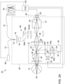
- FIG. 1 there is shown a high-level schematized representation of a spectroreflectometric system 20 for performing a spectral analysis on the fundus 30 of a patient's eye 21, illustrating a spectroreflectometric method according to one embodiment.
- the spectroreflectometric system 20 includes an imaging device 50, a spectral analyser 52 and a pointer light source 66. In this illustrated configuration, the spectroreflectometric system 20 is operable in two modes: an acquisition mode, and a pointer mode.
- the spectroreflectometric system 20 further includes an optical assembly defining an imaging light path 34 between the patient's eye 21 and the imaging device 50, and a spectral analysis light path 36 between the patient's eye 21 and the spectral analyser 52.
- acquisition mode the fundus 30 of the patient's eye 21 is illuminated, thereby obtaining return light 32 from the fundus 30 which propagates along the imaging light path 34.
- the return light 32 is preferably divided into an imaging portion 54 propagating along the imaging light path 32, and a spectral analysis portion 56 diverted to the spectral analysis light path 36.
- the imaging portion 54 is detected via the imaging device 50 to obtain an image of the fundus 30 of the patient's eye 21.
- the diverted spectral analysis portion 56 is detected using the spectral analyser 52 to obtain and a spectral analysis of an analysis spot on the fundus 30.
- the pointer light source 66 In the pointer mode, the pointer light source 66 generates a pointer light beam 68 which is coupled to the spectral analysis light path 36 such that the pointer light beam 68 is projected on the fundus of the patient's eye 21 at the analysis spot of the spectral analyser.
- analysis spot refers to a region or area on the fundus of the patient's eye or other medium under analysis from which the portion of the return light reaching the spectral analyser originates.
- the analysis spot may have different sizes and/or shapes mostly determined by the geometry and configuration of the spectroreflectometric system.
- FIG. 2A a schematized representation of a configuration embodying a spectroreflectometric system 20 according to one example is illustrated.
- the spectroreflectometric system 20 includes an imaging device 50.
- the imaging device 50 may be embodied by a CCD or CMOS sensor, or any surface that is sensitive and converts light intensity or energy into a useful signal.
- the imaging device 50 may include or be in communication with a processor, computer, circuit or any other hardware component or ensemble of hardware components programmed with instructions for constructing, storing and displaying the images acquired by the imaging device 50.
- An integrated or separate display may be provided to allow the viewing of the resulting images by an operator or user of the spectroreflectometric system 20.
- the spectral analyser 52 may be embodied by any suitable device allowing an analysis of light as a function of wavelength.
- the spectral analyser 52 may for example be embodied by an optical spectrometer.
- optical spectrometers typically decompose incoming light according to its spectrum, typically using light refraction (e.g. in a prism) or light diffraction (in a diffraction grating), and include a detector measuring the distributed intensity of the decomposed light.
- the spectral analyser 52 may include a computer or processor programmed with instructions to analyse the detected light spectrum in accordance with predetermined parameters, such as explained above.
- the spectral analyser 52 may be grating-based, as illustrated by way of example in FIG.
- the spectral analyser 52 may include at least one dispersive element such as grating in reflection or transmission or a prism.
- the spectroreflectometric system 20 may further included an illumination light source 22 operable to generate an illumination light 24, which can be projected towards the fundus 30 of the patient's eye 21 in the acquisition mode.
- the illumination light source 22 may include one or more LED (Light Emitting Diode) emitters.
- the LED emitters of a given illumination light source 22 may have similar optical properties or different complementary optical properties selected in order to obtain the desired optical properties of the illumination light 24 once combined. It will be readily understood that numerous other variants of light sources such as lasers, OLEDs, fluorescent, incandescent, tungsten, and other light bulbs may be used in alternative embodiments.
- illumination light is used herein to refer to electromagnetic radiation suitable for projection into the eye 21 of a patient and for inducing, producing or otherwise generating return light 32 which can yield information of interest on the fundus 30 of the patient's eye 21 upon suitable analysis. It will be readily understood that the term “light” is not considered limited to the visible portion of the electromagnetic spectrum.
- the illumination light 24 preferably has a broadband spectral profile encompassing all the wavelengths of interest for the spectral analysis which the system is configured to perform.
- the illumination light may be white light.
- the illumination light 24 may have a spectral profile designed in view of the field of use of the spectroreflectometric system 20.
- the illumination light may have any other suitable spectral profile as dictated by one or more factors such as the optical properties of the patient's eye, the availability of light sources, the nature and characteristics of the spectral analysis to be performed, etc.
- the spectroreflectometric system 20 includes an optical assembly 26 defining on one hand, the imaging light path 34 between the patient's eye 21 and the imaging device 50 and, on the other hand, the spectral analysis light path 36 between the patient's eye 21 and the spectral analyser 52.
- the optical assembly 26 may be embodied by a variety of configurations suitable to the purpose of illuminating a patient's eye and collecting the resulting return light.
- the optical assembly 26 may include one or more optical components configured to transfer the image of the fundus 30 onto an image plane 46.
- the optical components may include lenses, mirrors, polarizers, filters, etc.
- the optical components may be arranged in any suitable fashion as is generally known to those skilled in the art.
- the optical assembly 26 may further include other non-optical components such as mechanical or electrical components providing structural and/or functional support to the optical components such as fixed or displaceable mounts, screens, pinholes, step motors, etc.
- the optical assembly 26 may include an illumination subassembly 28 optically coupled to the illumination light source 22 and configured to project the illumination light 24 from the illumination light source 22 towards the fundus 30 of the patient's eye 21.
- the illumination subassembly 28 includes a holed mirror 38 positioned at an angle along the imaging light path 34.
- the holed mirror 38 has a central hole 39 aligned with the imaging light path 34.
- the illumination light source 22 is positioned orthogonally to the eye of the patent 21, and the holed mirror makes a 45° angle with respect to the optical axis of the illumination light 24.
- the illumination subassembly 28 may include one or more optical components having variable transmission and reflection properties, for example an mirror designed to have a low reflectivity in the enter and a high reflectivity around this center.
- the illumination subassembly 28 further includes beam shaping optics projecting the illumination light 24 from the illumination light source 22 onto the holed mirror 38 for reflection towards the fundus of the patient's eye.
- the beam shaping optics includes one or more optical components interacting with the illumination light 24.
- the beam shaping optics includes a first lens 40a, a second lens 40b and a third lens 40c successively disposed along the optical path between the illumination light source 22 to the holed mirror 38.
- a mask 42 is positioned between the second lens 40b and the third lens 40c. The mask 42 is optically aligned with the central hole 39 of the holed mirror 38 and is sized to block the center of the illumination beam 24.
- This configuration provides the illumination light 24 with an annulus shape so that it is reflected on the holed mirror 38.
- a screen 44 may be further provided between the first and second lenses 40a and 40b to prevent retroreflected light from the mask 42 from reaching the illumination light source 22.
- An output lens 41 and any other relevant optics may be provided between the holed mirror 38 and the eye of the patient 21.
- an alignment light source 43 may optionally be provided optically coupled to the illumination subassembly 28 such that an alignment light beam generated therefrom can be launched into the same optical path as the illumination light.
- the alignment light source 43 may generate light in the near infrared spectral range to avoid discomfort to the patient.
- the illumination subassembly 28 may be embodied by any suitable collection or optical components and accompanying structural, mechanical, electrical or other features collaborating to bring the illumination light from the illumination light source to the patient's eye with the desired optical characteristics.
- the components of the illumination subassembly may redirect, focus, collimate, filter or otherwise act on light in a variety of fashions.
- one or more optical fibers may be used to carry the illumination light 24 at least partially from the illumination light source 22 towards the fundus 30.
- the illumination light source 22 may be provided either separately or integrally to the optical assembly 26.
- the optical assembly 26 may include a light port configured to receive the illumination light directly or indirectly from the illumination light source.
- the optical assembly 26 further includes a beamsplitter 48, positioned along the imaging light path 34 and configured to direct an imaging portion 54 of the return light 32 to the imaging light path 34, and a spectral analysis portion 56 of the return light 32 to the spectral analysis light path 36.
- a beamsplitter 48 is configured and arranged to transmit through the imaging portion 54 of the return light 32 and reflect the spectral analysis portion 56 of the return light 32, in other variants it may be configured and arranged to reflect the imaging portion 54 towards the imaging device 50, and transmit through the spectral analysis portion 56 towards the spectral analyser 52.
- a focussing lens may be positioned between the holed mirror 38 and the beamsplitter 48.
- the focussing lens may be mounted on a suitable translation actuator allowing its displacement along the imaging light path 34. Such a movement displaces the imaging plane 46 to compensate for refractive index variations in the eye of different patients.
- the focussing lens may have a variable focus and may be adjustable by different means.
- the imaging portion 54 of the return light 32 travels along the imaging light path 34 until it reaches the imaging device 50 for detection.
- numerous optical components could be provided along the imaging light path to collimate, focus, filter, redirect or otherwise affect the imaging portion 54 prior to reaching the imaging device 50.
- Beamshaping optics 51 are indicated as a blackbox representation of such components in the illustrated configuration of FIG. 2A .
- the spectral analysis portion 56 of the return light 32 is deviated to the spectral analysis light path 36 and is eventually detected by the spectral analyser 52.
- the spectral analysis light path 36 is also optically coupled to the pointer light source 66 so that the pointer light beam 68 can counterpropagate along the spectral analysis light path 36 towards the beamsplitter 48.
- the operation of the pointer light source 66 and other features that may be provided along the spectral analysis light path 36 will be explained in further details below.
- the beamsplitter 48 may operate according to any one of various principles to separate the light impinging thereon according to different portions.
- the beamsplitter 48 is a dichroic beamsplitter.
- dichroic optical components affect light according to its spectral characteristics.
- the dichroic beamsplitter 48 may have a spectral transmission profile tailored to the operation of the spectroreflectometric system 20.
- the dichroic beamsplitter 48 has a transmission spectral profile defining:
- the graph of FIG. 3 illustrates an ideal spectral profile and practical implementations may only approximate such an ideal variation.
- the beamsplitter 48 may separate light according to other characteristics than its spectral contents.
- the beamsplitter 48 may for example be configured to divide the return light 32 travelling along the imaging light path 34 into the imaging portion and the spectral analysis portion according to intensity ratios independently of the light's wavelength or polarization state.
- the beamsplitter 48 may be configured to divide the return light 32 travelling along the imaging light path 34 into the imaging portion and the spectral analysis portion according to polarisation directions.
- the optical assembly 26 includes first and second optical fiber links 70 and 72.
- the first optical fiber link 70 extends between the spectral analysis light path 34 and the spectral analyser 52.
- the second optical fiber link 72 extends between the spectral analysis light path 34 and the pointer light source 66.
- the optical assembly 26 further includes a three-prong coupler 74 optically coupling the spectral analysis light path 34, the first optical fiber link 70 and the second optical fiber link 72.
- the three-prong coupler 74 may be embodied by various devices and/or configurations providing light circulation from the spectral analysis light path 36 to the first optical fiber link 70, allowing the spectral analysis portion 56 of the return light 32 to reach the spectral analyser 52, and from the second optical fiber link 72 to the spectral analysis path 36, allowing the pointer light beam 68 to be launched in the system towards the eye of the patient 21.
- FIGs. 4A to 4C different variants of the three-prong coupler 74 are illustrated.
- the three-prong coupler 74 includes a multimode optical circulator.
- the three-prong coupler 74 comprises a double-clad optical fiber, which may support the propagation of the pointer light beam in the core, and the light collection for spectral analysis region through the cladding sent to the spectral analyser.
- the core mode is optically coupled to the first optical fiber link
- the cladding mode is optically coupled to the second optical fiber link (or vice versa).
- the three-prong coupler 74 may be a free-space configuration, for example based on a free-space beamsplitting configuration 76.
- Beamshaping optics 78 are indicated as a blackbox representation of such components in the illustrated configuration of FIG. 2A .
- a lens 79 focussing light onto the three-prong coupler is also illustrated.
- the pointer light source 66 may be embodied by any light source generating a pointer light beam 68 suitable for pointing functionalities.
- the pointer light source 66 may be a laser diode.
- the pointer light beam 68 may have any wavelength or spectral contents safe for the eye of the patient and within the detection range of the imaging device.
- the pointer light source may for example emit in the visible or near infrared spectral ranges.
- the spectroreflectometric system 20 includes a controller 80.
- the controller 80 is configured to operate in the acquisition mode and in the pointer mode. In some implementations, the acquisition mode and pointer mode may be operated alternatively, whereas in other implementations they may be operated concurrently.
- the controller 80 operates the illumination light source 22, the imaging device 50 and the spectral analyser 52 to concurrently obtain an image of the fundus 30 of the patient's eye 21 and a spectral analysis of an analysis spot on this fundus 30.
- the controller 80 operates the pointer light source 66 and the imaging device 50 to obtain a visual representation of the analysis spot within the image obtained in the acquisition mode.
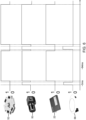
- FIG. 5A shows the visual representation of an analysis spot 82 obtained in the pointer mode, where the pointer light beam from the pointer light source is optically guided through the system to reach the fundus of the patient's eye.
- the obtained visual representation is an image of this point source onto the sensor of the imaging device. This image may be used as a "laser pointer" to define the area for which the spectral analysis is performed, since both optical fiber links 70 and 72 share the same output at the three-prong coupler 74.
- FIG. 5B shows the image 84 of the fundus and the spectral analysis 85 of the analysis spot defined by the pointer jointly obtained in acquisition mode.
- the controller includes precise synchronisation electronically enabling the successive operation of the system in the pointer mode and acquisition mode.
- the image and spectral analysis information shown in FIG. 5B may be obtained prior to the visual representation of the analysis spot shown in FIG. 5A .
- the position of the analysis spot obtained in pointer mode may be superimposed on the image of the retina obtained in acquisition mode, as shown in FIG. 5C .
- An oxygen concentration from the corresponding region may be jointly provided in oximetry applications.
- FIG. 6 shows a timing diagraph for control signals provided from the controller to the illumination light source 22, the imaging device 50, the spectral analyser 52 and the pointer light source 66, respectively.
- the spectroreflectometric system 20 may include additional components and functionalities.
- the spectroreflectometric system 20 may include a spot shifting mechanism 86 positioned in the spectral analysis path 36 and configured to shift the position of the analysis spot over the fundus 30 of the patient's eye without impact on the imaging portion 21.
- the spot shifting mechanism 86 may include shift optics such as one or more steerable mirrors. A pivoting of the steerable mirrors can be used to change the incidence angle between the pointer light beam 68 travelling along the spectral imaging light path 36 and the beamsplitter 48. Referring to FIGs. 7A and 7B , two examples of configurations of the spot shifting mechanism are shown. On FIG.
- first and second mirrors 88a, 88b with displacement both in phi and theta direction are used to change the angle of incidence of the pointer light beam 68 onto the beamsplitter 48.
- the direction of displacement of the first mirror 88a must be opposite to the one of the second mirror 88b in order to keep the position of the pointer light beam 68 on the beamsplitter 48 and to only change the angle of incidence.
- a gimbal mirror 89 is used in place of the second mirror 88b.
- This scheme used jointly with two lenses 90a and 90b used in 4f configuration, enables the variation of the angle of incidence of the pointer light beam 68 onto the beamsplitter 48 without changing the position at which the pointer light beam 68 hits the beamsplitter.
- FIG. 2B there is shown a variant of the spectroreflectometric system 20 similar to the one described above, for use in performing a spectral analysis on a medium other than the fundus of the eye.
- the medium under study is a pocket of liquid 23 (for example containing blood or plasma).
- the spectroreflectometric system of FIG. 2B includes all the same components as the system shown in FIG. 2A , including the optical assembly 26 and illumination subassembly 28.
- the illumination subassembly 28 further includes an additional output lens 41'.
- the additional output lens 41' can be added to the configuration of FIG. 2A to provide focalization and form an image of the medium being probed on the imaging device 50.
- this approach can provide an easy adaptation of a system initially conceived to probe the fundus of the eye, since such a conception considers the natural light focalisation performed by the lens of the eye, which is in essence replaced by the additional output lens 41'.
- the output lens 41 and additional output lens 41' may be replaced by a single lens or different optical arrangement.
Landscapes
- Health & Medical Sciences (AREA)
- Life Sciences & Earth Sciences (AREA)
- Physics & Mathematics (AREA)
- Medical Informatics (AREA)
- Surgery (AREA)
- Biophysics (AREA)
- Veterinary Medicine (AREA)
- Engineering & Computer Science (AREA)
- Biomedical Technology (AREA)
- Heart & Thoracic Surgery (AREA)
- Public Health (AREA)
- Molecular Biology (AREA)
- General Health & Medical Sciences (AREA)
- Animal Behavior & Ethology (AREA)
- Spectroscopy & Molecular Physics (AREA)
- Ophthalmology & Optometry (AREA)
- Pathology (AREA)
- General Physics & Mathematics (AREA)
- Optics & Photonics (AREA)
- Eye Examination Apparatus (AREA)
- Investigating Or Analysing Materials By Optical Means (AREA)
Claims (10)
- Système spectroréflectrométrique (20) pour réaliser une analyse spectrale sur le fond (30) de l'œil d'un patient (21), comprenant :- un dispositif d'imagerie (50) :- un analyseur spectral (52) ;- un ensemble optique (26) définissant un trajet de lumière d'imagerie (34) entre l'œil du patient (21) et le dispositif d'imagerie (50) et un trajet de lumière d'analyse spectrale (36) entre l'œil du patient (21) et l'analyseur spectral (52), l'ensemble optique comprenant un diviseur de faisceau (48) positionné le long du trajet de lumière d'imagerie (34) et configuré pour diriger une partie d'imagerie (54) de lumière se déplaçant le long du trajet de lumière d'imagerie (34) vers le dispositif d'imagerie (50) et une partie d'analyse spectrale (56) de ladite lumière vers le trajet de lumière d'analyse spectrale (36) ;caractérisé en ce qu'il comprend en outre une source de lumière de pointeur (66) servant à générer un faisceau de lumière de pointeur (68) et optiquement couplée au trajet de lumière d'analyse spectrale (36) de telle sorte que le faisceau de lumière de pointeur (68) peut se rétropropager le long du trajet de lumière d'analyse spectrale (36) vers le diviseur de faisceau de sorte que ledit faisceau de lumière de pointeur (68) est projetable sur le fond (30) de l'œil du patient (21) au niveau d'un point d'analyse (82) dudit analyseur spectral (52).
- Système spectroréflectrométrique (20) selon la revendication 1, dans lequel le diviseur de faisceau (48) est un diviseur de faisceau dichroïque.
- Système spectroréflectrométrique (20) selon la revendication 2, dans lequel le diviseur de faisceau (48) est configuré pour diviser la lumière se déplaçant le long du trajet de lumière d'imagerie (34) en la partie d'imagerie (54) et en la partie d'analyse spectrale (56) selon des rapports d'intensité ou des directions de polarisation.
- Système spectroréflectrométrique (20) selon l'une quelconque des revendications 1 à 3,
dans lequel l'ensemble optique (26) comprend :- une première liaison à fibre optique (70) s'étendant entre le trajet de lumière d'analyse spectrale (36) et l'analyseur spectral (52) ;- une deuxième liaison à fibre optique (72) s'étendant entre le trajet de lumière d'analyse spectrale (36) et la source de lumière de pointeur (66) ; et- un coupleur à trois broches (74) couplant optiquement le trajet de lumière d'analyse spectrale (36), la première liaison à fibre optique (70) et la deuxième liaison à fibre optique (72), ledit coupleur à trois broches (74) comprenant de préférence l'un d'un circulateur optique multimode, d'une fibre optique double gaine ou d'une configuration de division de faisceau en espace libre. - Système spectroréflectrométrique (20) selon l'une quelconque des revendications 1 à 4,
dans lequel l'ensemble optique (26) comprend un sous-ensemble d'éclairage (28) configuré pour projeter de la lumière d'éclairage (24) vers le fond (30) de l'œil du patient (21), et comprend éventuellement une source de lumière d'éclairage (22) servant à générer la lumière d'éclairage (24) et couplée optiquement au sous-ensemble d'éclairage (28). - Système spectroréflectrométrique (20) selon la revendication 5, dans lequel le sous-ensemble d'éclairage (28) comprend :- un miroir percé (38) positionné en biais le long du trajet de lumière d'imagerie (34) entre l'œil du patient (21) et le diviseur de faisceau (48), le miroir percé (38) ayant un trou central (39) aligné avec le trajet de lumière d'imagerie (34) ; et- un dispositif optique de mise en forme de faisceaux (40a, 40b, 40c, 42, 44) projetant la lumière d'éclairage (24) depuis la source de lumière d'éclairage (22) sur le miroir percé (38) pour une réflexion vers le fond de l'œil du patient.
- Système spectroréflectrométrique (20) selon la revendication 6, dans lequel le dispositif optique de mise en forme de faisceaux du sous-ensemble d'éclairage (28) comprend un écran (44) bloquant un centre de la lumière d'éclairage (24) et optiquement aligné avec le trou central (39) du miroir percé (38).
- Système spectroréflectrométrique (20) selon l'une quelconque des revendications 1 à 7, comprenant en outre un dispositif de commande (80) configuré pour fonctionner dans :- un mode d'acquisition dans lequel le dispositif de commande (80) fait fonctionner le dispositif d'imagerie (50) et l'analyseur spectral (52) pour obtenir simultanément une image (84) du fond (30) de l'œil du patient (21) et une analyse spectrale (85) du point d'analyse (82) sur ledit fond (30) ; et- un mode pointeur dans lequel le dispositif de commande (80) fait fonctionner la source de lumière de pointeur (66) et le dispositif d'imagerie (50) pour obtenir une représentation visuelle du point d'analyse (82) au sein de ladite image (84).
- Système spectroréflectrométrique (20) selon l'une quelconque des revendications 1 à 8, comprenant en outre un mécanisme de décalage de point (86) positionné dans le trajet de lumière d'analyse spectrale (36) et configuré pour décaler une position du point d'analyse (82) sur ledit fond (30) de l'œil du patient (21), ledit mécanisme de décalage de point (86) comprenant éventuellement un dispositif optique de décalage (86) comprenant au moins un miroir orientable (88) pour modifier l'angle d'incidence entre le trajet de lumière d'analyse spectrale (36) et le diviseur de faisceau (48).
- Procédé spectroréflectrométrique pour réaliser une analyse spectrale sur le fond de l'œil d'un patient, comprenant :- la fourniture d'un système spectroréflectrométrique pouvant fonctionner dans un mode d'acquisition et dans un mode pointeur ;- dans le mode d'acquisition :º l'éclairage du fond de l'œil du patient, obtenant ainsi une lumière de retour dudit fond, la lumière de retour se propageant le long d'un trajet de lumière d'imagerie ;º la séparation de la lumière de retour en une partie d'imagerie continuant le long du trajet de lumière d'imagerie, et en une partie d'analyse spectrale déviée vers un trajet de lumière d'analyse spectrale ;º la détection de la partie d'imagerie en utilisant un dispositif d'imagerie pour obtenir une image du fond de l'œil du patient ;º la détection de la partie d'analyse spectrale en utilisant un analyseur spectral pour obtenir et une analyse spectrale d'un point d'analyse sur ledit fond ; et- dans le mode pointeur :º le couplage d'un faisceau de lumière de pointeur au trajet de lumière d'analyse spectrale de telle sorte que ledit faisceau de lumière de pointeur est projeté vers le fond de l'œil du patient et qu'une réflexion de celui-ci est propagée le long du trajet de lumière d'imagerie vers le dispositif d'imagerie ;º la détection de la réflexion du faisceau de lumière de pointeur en utilisant le dispositif d'imagerie pour obtenir une représentation visuelle du point d'analyse au sein de ladite image.
Applications Claiming Priority (3)
| Application Number | Priority Date | Filing Date | Title |
|---|---|---|---|
| US201762595260P | 2017-12-06 | 2017-12-06 | |
| US201862672916P | 2018-05-17 | 2018-05-17 | |
| PCT/CA2018/051559 WO2019109186A1 (fr) | 2017-12-06 | 2018-12-05 | Système spectroréflectométrique comportant un mode de pointage pour une imagerie et une analyse spectrale combinées |
Publications (4)
| Publication Number | Publication Date |
|---|---|
| EP3720337A1 EP3720337A1 (fr) | 2020-10-14 |
| EP3720337A4 EP3720337A4 (fr) | 2021-08-25 |
| EP3720337B1 true EP3720337B1 (fr) | 2024-05-29 |
| EP3720337C0 EP3720337C0 (fr) | 2024-05-29 |
Family
ID=66750661
Family Applications (1)
| Application Number | Title | Priority Date | Filing Date |
|---|---|---|---|
| EP18885321.2A Active EP3720337B1 (fr) | 2017-12-06 | 2018-12-05 | Système spectroréflectométrique comportant un mode de pointage pour une imagerie et une analyse spectrale combinées |
Country Status (6)
| Country | Link |
|---|---|
| US (1) | US11375894B2 (fr) |
| EP (1) | EP3720337B1 (fr) |
| JP (1) | JP7230052B2 (fr) |
| CN (1) | CN111757699B (fr) |
| ES (1) | ES2981379T3 (fr) |
| WO (1) | WO2019109186A1 (fr) |
Families Citing this family (6)
| Publication number | Priority date | Publication date | Assignee | Title |
|---|---|---|---|---|
| TWI820406B (zh) * | 2021-03-24 | 2023-11-01 | 立克銘白生醫股份有限公司 | 用於檢測生物粒子的檢測設備及檢測設備的檢測方法 |
| US12582290B2 (en) * | 2021-04-01 | 2026-03-24 | Gyrus Acmi, Inc. | Techniques for composition identification of an anatomical target |
| DE102021205328B3 (de) * | 2021-05-26 | 2022-09-29 | Carl Zeiss Smt Gmbh | Verfahren zur Bestimmung einer Abbildungsqualität eines optischen Systems bei Beleuchtung mit Beleuchtungslicht innerhalb einer zu vermessenden Pupille und Metrologiesystem dafür |
| CN114145708A (zh) * | 2021-12-27 | 2022-03-08 | Oppo广东移动通信有限公司 | 眼底摄像模组以及眼底摄像系统 |
| WO2024103176A1 (fr) * | 2022-11-15 | 2024-05-23 | Zilia Inc. | Dispositif multimodal pour acquisitions spectrales et tco |
| CN118490161B (zh) * | 2024-07-12 | 2024-09-27 | 西北工业大学宁波研究院 | 一种眼底成像的高光谱检测装置及方法 |
Family Cites Families (15)
| Publication number | Priority date | Publication date | Assignee | Title |
|---|---|---|---|---|
| US5308919A (en) * | 1992-04-27 | 1994-05-03 | Minnich Thomas E | Method and apparatus for monitoring the arteriovenous oxygen difference from the ocular fundus |
| JP3539816B2 (ja) * | 1996-01-31 | 2004-07-07 | 株式会社ニデック | 眼底カメラ |
| US6149589A (en) | 1998-03-26 | 2000-11-21 | Universite De Montreal | On-line and real-time spectroreflectometry measurement of oxygenation in a patient's eye |
| US5919132A (en) * | 1998-03-26 | 1999-07-06 | Universite De Montreal | On-line and real-time spectroreflectometry measurement of oxygenation in a patient's eye |
| US6069690A (en) * | 1998-11-13 | 2000-05-30 | Uniphase Corporation | Integrated laser imaging and spectral analysis system |
| US6826424B1 (en) * | 2000-12-19 | 2004-11-30 | Haishan Zeng | Methods and apparatus for fluorescence and reflectance imaging and spectroscopy and for contemporaneous measurements of electromagnetic radiation with multiple measuring devices |
| WO2003009750A2 (fr) | 2001-07-25 | 2003-02-06 | Sarnoff Corporation | Systeme et procede permettant de determiner l'oxygenation cerebrale |
| JP4469977B2 (ja) | 2004-07-09 | 2010-06-02 | 日本電信電話株式会社 | 歯の光干渉トモグラフィー装置 |
| JP2005296434A (ja) | 2004-04-14 | 2005-10-27 | Kowa Co | 分光画像解析方法及び装置 |
| CN101862180A (zh) * | 2009-04-16 | 2010-10-20 | 南京理工大学 | 近红外光谱双视场干涉成像装置 |
| CN102499635A (zh) * | 2011-10-26 | 2012-06-20 | 中国科学院光电技术研究所 | 一种基于线扫描的眼底视网膜多光谱成像系统和方法 |
| PL3011288T3 (pl) * | 2013-06-20 | 2021-06-28 | Cylite Pty Ltd | Metrologia oczna wykorzystująca widmową analizę czoła fali światła odbitego |
| US10568506B2 (en) * | 2016-12-22 | 2020-02-25 | Zilia Inc. | Optical fiber-based spectroreflectometric system |
| US10708574B2 (en) * | 2017-06-15 | 2020-07-07 | Align Technology, Inc. | Three dimensional imaging apparatus with color sensor |
| US11737665B2 (en) * | 2019-06-21 | 2023-08-29 | Tesseract Health, Inc. | Multi-modal eye imaging with shared optical path |
-
2018
- 2018-12-05 CN CN201880088738.4A patent/CN111757699B/zh active Active
- 2018-12-05 ES ES18885321T patent/ES2981379T3/es active Active
- 2018-12-05 JP JP2020549843A patent/JP7230052B2/ja active Active
- 2018-12-05 WO PCT/CA2018/051559 patent/WO2019109186A1/fr not_active Ceased
- 2018-12-05 EP EP18885321.2A patent/EP3720337B1/fr active Active
-
2020
- 2020-06-08 US US16/895,487 patent/US11375894B2/en active Active
Also Published As
| Publication number | Publication date |
|---|---|
| WO2019109186A8 (fr) | 2020-04-09 |
| JP7230052B2 (ja) | 2023-02-28 |
| EP3720337A4 (fr) | 2021-08-25 |
| WO2019109186A1 (fr) | 2019-06-13 |
| CN111757699B (zh) | 2024-03-01 |
| US20200297208A1 (en) | 2020-09-24 |
| CA3084027A1 (fr) | 2019-06-13 |
| ES2981379T3 (es) | 2024-10-08 |
| JP2021505340A (ja) | 2021-02-18 |
| US11375894B2 (en) | 2022-07-05 |
| WO2019109186A9 (fr) | 2020-05-07 |
| EP3720337A1 (fr) | 2020-10-14 |
| CN111757699A (zh) | 2020-10-09 |
| EP3720337C0 (fr) | 2024-05-29 |
Similar Documents
| Publication | Publication Date | Title |
|---|---|---|
| US11375894B2 (en) | Spectroreflectometric system provided with a pointer mode for combined imaging and spectral analysis | |
| JP7414807B2 (ja) | ハイパースペクトル装置及び方法 | |
| EP2441382B1 (fr) | Appareil d'alignement optique | |
| JP2003533320A (ja) | 眼の屈折誤差を測定するための方法及び装置 | |
| WO2018113585A1 (fr) | Élément optique destiné à une imagerie rétinienne et dispositif d'imagerie rétinienne | |
| CN106166056A (zh) | 多光谱眼底成像系统 | |
| WO2022057402A1 (fr) | Système de détection tridimensionnelle de fond d'œil fonctionnel à grande vitesse fondé sur une lumière proche infrarouge | |
| US12259327B2 (en) | System and method for performing a photoluminescence analysis on a medium | |
| CN112587080A (zh) | 可见光和近红外光双波段光学相干断层扫描成像系统 | |
| US20090118601A1 (en) | Ir spectrographic apparatus and method for diagnosis of disease | |
| CA3084027C (fr) | Système spectroréflectométrique ayant un mode pointeur pour une imagerie et une analyse spectrale combinées | |
| CA3007551C (fr) | Systeme spectroreflectrometrique a base de fibres optiques | |
| CA3231496C (fr) | Dispositif multimodal pour les acquisitions spectrales et de tomographie par cohérence optique | |
| Shi et al. | Fundus Spectral Imaging: From Optical Systems to Clinical Applications | |
| CN119138840A (zh) | 一种眼科光学成像系统 | |
| GB2487873A (en) | Optical measurement apparatus and method therefor | |
| WO2024103176A1 (fr) | Dispositif multimodal pour acquisitions spectrales et tco |
Legal Events
| Date | Code | Title | Description |
|---|---|---|---|
| STAA | Information on the status of an ep patent application or granted ep patent |
Free format text: STATUS: THE INTERNATIONAL PUBLICATION HAS BEEN MADE |
|
| PUAI | Public reference made under article 153(3) epc to a published international application that has entered the european phase |
Free format text: ORIGINAL CODE: 0009012 |
|
| STAA | Information on the status of an ep patent application or granted ep patent |
Free format text: STATUS: REQUEST FOR EXAMINATION WAS MADE |
|
| 17P | Request for examination filed |
Effective date: 20200706 |
|
| AK | Designated contracting states |
Kind code of ref document: A1 Designated state(s): AL AT BE BG CH CY CZ DE DK EE ES FI FR GB GR HR HU IE IS IT LI LT LU LV MC MK MT NL NO PL PT RO RS SE SI SK SM TR |
|
| AX | Request for extension of the european patent |
Extension state: BA ME |
|
| DAV | Request for validation of the european patent (deleted) | ||
| DAX | Request for extension of the european patent (deleted) | ||
| A4 | Supplementary search report drawn up and despatched |
Effective date: 20210723 |
|
| RIC1 | Information provided on ipc code assigned before grant |
Ipc: A61B 3/12 20060101AFI20210719BHEP Ipc: A61B 3/14 20060101ALI20210719BHEP Ipc: A61B 5/1455 20060101ALI20210719BHEP Ipc: A61B 3/00 20060101ALI20210719BHEP Ipc: A61B 5/00 20060101ALI20210719BHEP |
|
| STAA | Information on the status of an ep patent application or granted ep patent |
Free format text: STATUS: EXAMINATION IS IN PROGRESS |
|
| 17Q | First examination report despatched |
Effective date: 20230320 |
|
| GRAP | Despatch of communication of intention to grant a patent |
Free format text: ORIGINAL CODE: EPIDOSNIGR1 |
|
| STAA | Information on the status of an ep patent application or granted ep patent |
Free format text: STATUS: GRANT OF PATENT IS INTENDED |
|
| INTG | Intention to grant announced |
Effective date: 20240221 |
|
| GRAS | Grant fee paid |
Free format text: ORIGINAL CODE: EPIDOSNIGR3 |
|
| GRAA | (expected) grant |
Free format text: ORIGINAL CODE: 0009210 |
|
| STAA | Information on the status of an ep patent application or granted ep patent |
Free format text: STATUS: THE PATENT HAS BEEN GRANTED |
|
| AK | Designated contracting states |
Kind code of ref document: B1 Designated state(s): AL AT BE BG CH CY CZ DE DK EE ES FI FR GB GR HR HU IE IS IT LI LT LU LV MC MK MT NL NO PL PT RO RS SE SI SK SM TR |
|
| RAP3 | Party data changed (applicant data changed or rights of an application transferred) |
Owner name: ZILIA INC. |
|
| REG | Reference to a national code |
Ref country code: CH Ref legal event code: EP |
|
| REG | Reference to a national code |
Ref country code: IE Ref legal event code: FG4D |
|
| REG | Reference to a national code |
Ref country code: DE Ref legal event code: R096 Ref document number: 602018070181 Country of ref document: DE |
|
| U01 | Request for unitary effect filed |
Effective date: 20240620 |
|
| U07 | Unitary effect registered |
Designated state(s): AT BE BG DE DK EE FI FR IT LT LU LV MT NL PT SE SI Effective date: 20240702 |
|
| PG25 | Lapsed in a contracting state [announced via postgrant information from national office to epo] |
Ref country code: IS Free format text: LAPSE BECAUSE OF FAILURE TO SUBMIT A TRANSLATION OF THE DESCRIPTION OR TO PAY THE FEE WITHIN THE PRESCRIBED TIME-LIMIT Effective date: 20240929 |
|
| REG | Reference to a national code |
Ref country code: ES Ref legal event code: FG2A Ref document number: 2981379 Country of ref document: ES Kind code of ref document: T3 Effective date: 20241008 |
|
| PG25 | Lapsed in a contracting state [announced via postgrant information from national office to epo] |
Ref country code: HR Free format text: LAPSE BECAUSE OF FAILURE TO SUBMIT A TRANSLATION OF THE DESCRIPTION OR TO PAY THE FEE WITHIN THE PRESCRIBED TIME-LIMIT Effective date: 20240529 |
|
| PG25 | Lapsed in a contracting state [announced via postgrant information from national office to epo] |
Ref country code: GR Free format text: LAPSE BECAUSE OF FAILURE TO SUBMIT A TRANSLATION OF THE DESCRIPTION OR TO PAY THE FEE WITHIN THE PRESCRIBED TIME-LIMIT Effective date: 20240830 |
|
| PG25 | Lapsed in a contracting state [announced via postgrant information from national office to epo] |
Ref country code: PL Free format text: LAPSE BECAUSE OF FAILURE TO SUBMIT A TRANSLATION OF THE DESCRIPTION OR TO PAY THE FEE WITHIN THE PRESCRIBED TIME-LIMIT Effective date: 20240529 |
|
| PG25 | Lapsed in a contracting state [announced via postgrant information from national office to epo] |
Ref country code: PL Free format text: LAPSE BECAUSE OF FAILURE TO SUBMIT A TRANSLATION OF THE DESCRIPTION OR TO PAY THE FEE WITHIN THE PRESCRIBED TIME-LIMIT Effective date: 20240529 Ref country code: NO Free format text: LAPSE BECAUSE OF FAILURE TO SUBMIT A TRANSLATION OF THE DESCRIPTION OR TO PAY THE FEE WITHIN THE PRESCRIBED TIME-LIMIT Effective date: 20240829 Ref country code: IS Free format text: LAPSE BECAUSE OF FAILURE TO SUBMIT A TRANSLATION OF THE DESCRIPTION OR TO PAY THE FEE WITHIN THE PRESCRIBED TIME-LIMIT Effective date: 20240929 Ref country code: HR Free format text: LAPSE BECAUSE OF FAILURE TO SUBMIT A TRANSLATION OF THE DESCRIPTION OR TO PAY THE FEE WITHIN THE PRESCRIBED TIME-LIMIT Effective date: 20240529 Ref country code: GR Free format text: LAPSE BECAUSE OF FAILURE TO SUBMIT A TRANSLATION OF THE DESCRIPTION OR TO PAY THE FEE WITHIN THE PRESCRIBED TIME-LIMIT Effective date: 20240830 Ref country code: RS Free format text: LAPSE BECAUSE OF FAILURE TO SUBMIT A TRANSLATION OF THE DESCRIPTION OR TO PAY THE FEE WITHIN THE PRESCRIBED TIME-LIMIT Effective date: 20240829 |
|
| PG25 | Lapsed in a contracting state [announced via postgrant information from national office to epo] |
Ref country code: CZ Free format text: LAPSE BECAUSE OF FAILURE TO SUBMIT A TRANSLATION OF THE DESCRIPTION OR TO PAY THE FEE WITHIN THE PRESCRIBED TIME-LIMIT Effective date: 20240529 |
|
| PG25 | Lapsed in a contracting state [announced via postgrant information from national office to epo] |
Ref country code: SK Free format text: LAPSE BECAUSE OF FAILURE TO SUBMIT A TRANSLATION OF THE DESCRIPTION OR TO PAY THE FEE WITHIN THE PRESCRIBED TIME-LIMIT Effective date: 20240529 Ref country code: RO Free format text: LAPSE BECAUSE OF FAILURE TO SUBMIT A TRANSLATION OF THE DESCRIPTION OR TO PAY THE FEE WITHIN THE PRESCRIBED TIME-LIMIT Effective date: 20240529 |
|
| PG25 | Lapsed in a contracting state [announced via postgrant information from national office to epo] |
Ref country code: SM Free format text: LAPSE BECAUSE OF FAILURE TO SUBMIT A TRANSLATION OF THE DESCRIPTION OR TO PAY THE FEE WITHIN THE PRESCRIBED TIME-LIMIT Effective date: 20240529 |
|
| PG25 | Lapsed in a contracting state [announced via postgrant information from national office to epo] |
Ref country code: SM Free format text: LAPSE BECAUSE OF FAILURE TO SUBMIT A TRANSLATION OF THE DESCRIPTION OR TO PAY THE FEE WITHIN THE PRESCRIBED TIME-LIMIT Effective date: 20240529 Ref country code: SK Free format text: LAPSE BECAUSE OF FAILURE TO SUBMIT A TRANSLATION OF THE DESCRIPTION OR TO PAY THE FEE WITHIN THE PRESCRIBED TIME-LIMIT Effective date: 20240529 Ref country code: RO Free format text: LAPSE BECAUSE OF FAILURE TO SUBMIT A TRANSLATION OF THE DESCRIPTION OR TO PAY THE FEE WITHIN THE PRESCRIBED TIME-LIMIT Effective date: 20240529 Ref country code: CZ Free format text: LAPSE BECAUSE OF FAILURE TO SUBMIT A TRANSLATION OF THE DESCRIPTION OR TO PAY THE FEE WITHIN THE PRESCRIBED TIME-LIMIT Effective date: 20240529 |
|
| U20 | Renewal fee for the european patent with unitary effect paid |
Year of fee payment: 7 Effective date: 20241227 |
|
| PLBE | No opposition filed within time limit |
Free format text: ORIGINAL CODE: 0009261 |
|
| STAA | Information on the status of an ep patent application or granted ep patent |
Free format text: STATUS: NO OPPOSITION FILED WITHIN TIME LIMIT |
|
| 26N | No opposition filed |
Effective date: 20250303 |
|
| PG25 | Lapsed in a contracting state [announced via postgrant information from national office to epo] |
Ref country code: MC Free format text: LAPSE BECAUSE OF FAILURE TO SUBMIT A TRANSLATION OF THE DESCRIPTION OR TO PAY THE FEE WITHIN THE PRESCRIBED TIME-LIMIT Effective date: 20240529 |
|
| REG | Reference to a national code |
Ref country code: CH Ref legal event code: PL |
|
| PG25 | Lapsed in a contracting state [announced via postgrant information from national office to epo] |
Ref country code: CH Free format text: LAPSE BECAUSE OF NON-PAYMENT OF DUE FEES Effective date: 20241231 |
|
| PG25 | Lapsed in a contracting state [announced via postgrant information from national office to epo] |
Ref country code: IE Free format text: LAPSE BECAUSE OF NON-PAYMENT OF DUE FEES Effective date: 20241205 |
|
| PGFP | Annual fee paid to national office [announced via postgrant information from national office to epo] |
Ref country code: GB Payment date: 20251219 Year of fee payment: 8 |
|
| U20 | Renewal fee for the european patent with unitary effect paid |
Year of fee payment: 8 Effective date: 20251230 |
|
| PG25 | Lapsed in a contracting state [announced via postgrant information from national office to epo] |
Ref country code: CY Free format text: LAPSE BECAUSE OF FAILURE TO SUBMIT A TRANSLATION OF THE DESCRIPTION OR TO PAY THE FEE WITHIN THE PRESCRIBED TIME-LIMIT; INVALID AB INITIO Effective date: 20181205 |
|
| PGFP | Annual fee paid to national office [announced via postgrant information from national office to epo] |
Ref country code: ES Payment date: 20260130 Year of fee payment: 8 |