EP3720378B1 - Katheter und verfahren zur katheteranordnung - Google Patents
Katheter und verfahren zur katheteranordnung Download PDFInfo
- Publication number
- EP3720378B1 EP3720378B1 EP18819211.6A EP18819211A EP3720378B1 EP 3720378 B1 EP3720378 B1 EP 3720378B1 EP 18819211 A EP18819211 A EP 18819211A EP 3720378 B1 EP3720378 B1 EP 3720378B1
- Authority
- EP
- European Patent Office
- Prior art keywords
- catheter
- flexible substrate
- connectors
- sensors
- layers
- Prior art date
- Legal status (The legal status is an assumption and is not a legal conclusion. Google has not performed a legal analysis and makes no representation as to the accuracy of the status listed.)
- Active
Links
Images

Classifications
-
- A—HUMAN NECESSITIES
- A61—MEDICAL OR VETERINARY SCIENCE; HYGIENE
- A61B—DIAGNOSIS; SURGERY; IDENTIFICATION
- A61B18/00—Surgical instruments, devices or methods for transferring non-mechanical forms of energy to or from the body
- A61B18/04—Surgical instruments, devices or methods for transferring non-mechanical forms of energy to or from the body by heating
- A61B18/12—Surgical instruments, devices or methods for transferring non-mechanical forms of energy to or from the body by heating by passing a current through the tissue to be heated, e.g. high-frequency current
- A61B18/14—Probes or electrodes therefor
- A61B18/1492—Probes or electrodes therefor having a flexible, catheter-like structure, e.g. for heart ablation
-
- A—HUMAN NECESSITIES
- A61—MEDICAL OR VETERINARY SCIENCE; HYGIENE
- A61B—DIAGNOSIS; SURGERY; IDENTIFICATION
- A61B5/00—Measuring for diagnostic purposes; Identification of persons
- A61B5/06—Devices, other than using radiation, for detecting or locating foreign bodies ; Determining position of diagnostic devices within or on the body of the patient
- A61B5/061—Determining position of a probe within the body employing means separate from the probe, e.g. sensing internal probe position employing impedance electrodes on the surface of the body
- A61B5/062—Determining position of a probe within the body employing means separate from the probe, e.g. sensing internal probe position employing impedance electrodes on the surface of the body using magnetic field
-
- A—HUMAN NECESSITIES
- A61—MEDICAL OR VETERINARY SCIENCE; HYGIENE
- A61B—DIAGNOSIS; SURGERY; IDENTIFICATION
- A61B5/00—Measuring for diagnostic purposes; Identification of persons
- A61B5/06—Devices, other than using radiation, for detecting or locating foreign bodies ; Determining position of diagnostic devices within or on the body of the patient
- A61B5/065—Determining position of the probe employing exclusively positioning means located on or in the probe, e.g. using position sensors arranged on the probe
-
- A—HUMAN NECESSITIES
- A61—MEDICAL OR VETERINARY SCIENCE; HYGIENE
- A61B—DIAGNOSIS; SURGERY; IDENTIFICATION
- A61B5/00—Measuring for diagnostic purposes; Identification of persons
- A61B5/24—Detecting, measuring or recording bioelectric or biomagnetic signals of the body or parts thereof
- A61B5/25—Bioelectric electrodes therefor
- A61B5/279—Bioelectric electrodes therefor specially adapted for particular uses
- A61B5/28—Bioelectric electrodes therefor specially adapted for particular uses for electrocardiography [ECG]
- A61B5/283—Invasive
- A61B5/287—Holders for multiple electrodes, e.g. electrode catheters for electrophysiological study [EPS]
-
- A—HUMAN NECESSITIES
- A61—MEDICAL OR VETERINARY SCIENCE; HYGIENE
- A61B—DIAGNOSIS; SURGERY; IDENTIFICATION
- A61B5/00—Measuring for diagnostic purposes; Identification of persons
- A61B5/68—Arrangements of detecting, measuring or recording means, e.g. sensors, in relation to patient
- A61B5/6846—Arrangements of detecting, measuring or recording means, e.g. sensors, in relation to patient specially adapted to be brought in contact with an internal body part, i.e. invasive
- A61B5/6847—Arrangements of detecting, measuring or recording means, e.g. sensors, in relation to patient specially adapted to be brought in contact with an internal body part, i.e. invasive mounted on an invasive device
- A61B5/6852—Catheters
-
- A—HUMAN NECESSITIES
- A61—MEDICAL OR VETERINARY SCIENCE; HYGIENE
- A61M—DEVICES FOR INTRODUCING MEDIA INTO, OR ONTO, THE BODY; DEVICES FOR TRANSDUCING BODY MEDIA OR FOR TAKING MEDIA FROM THE BODY; DEVICES FOR PRODUCING OR ENDING SLEEP OR STUPOR
- A61M25/00—Catheters; Hollow probes
- A61M25/0009—Making of catheters or other medical or surgical tubes
-
- H—ELECTRICITY
- H01—ELECTRIC ELEMENTS
- H01R—ELECTRICALLY-CONDUCTIVE CONNECTIONS; STRUCTURAL ASSOCIATIONS OF A PLURALITY OF MUTUALLY-INSULATED ELECTRICAL CONNECTING ELEMENTS; COUPLING DEVICES; CURRENT COLLECTORS
- H01R43/00—Apparatus or processes specially adapted for manufacturing, assembling, maintaining, or repairing of line connectors or current collectors or for joining electric conductors
- H01R43/26—Apparatus or processes specially adapted for manufacturing, assembling, maintaining, or repairing of line connectors or current collectors or for joining electric conductors for engaging or disengaging the two parts of a coupling device
-
- H—ELECTRICITY
- H05—ELECTRIC TECHNIQUES NOT OTHERWISE PROVIDED FOR
- H05K—PRINTED CIRCUITS; CASINGS OR CONSTRUCTIONAL DETAILS OF ELECTRIC APPARATUS; MANUFACTURE OF ASSEMBLAGES OF ELECTRICAL COMPONENTS
- H05K3/00—Apparatus or processes for manufacturing printed circuits
- H05K3/22—Secondary treatment of printed circuits
- H05K3/28—Applying non-metallic protective coatings
- H05K3/281—Applying non-metallic protective coatings by means of a preformed insulating foil
-
- A—HUMAN NECESSITIES
- A61—MEDICAL OR VETERINARY SCIENCE; HYGIENE
- A61B—DIAGNOSIS; SURGERY; IDENTIFICATION
- A61B18/00—Surgical instruments, devices or methods for transferring non-mechanical forms of energy to or from the body
- A61B2018/00315—Surgical instruments, devices or methods for transferring non-mechanical forms of energy to or from the body for treatment of particular body parts
- A61B2018/00345—Vascular system
- A61B2018/00351—Heart
-
- A—HUMAN NECESSITIES
- A61—MEDICAL OR VETERINARY SCIENCE; HYGIENE
- A61B—DIAGNOSIS; SURGERY; IDENTIFICATION
- A61B18/00—Surgical instruments, devices or methods for transferring non-mechanical forms of energy to or from the body
- A61B2018/00315—Surgical instruments, devices or methods for transferring non-mechanical forms of energy to or from the body for treatment of particular body parts
- A61B2018/00345—Vascular system
- A61B2018/00351—Heart
- A61B2018/00357—Endocardium
-
- A—HUMAN NECESSITIES
- A61—MEDICAL OR VETERINARY SCIENCE; HYGIENE
- A61B—DIAGNOSIS; SURGERY; IDENTIFICATION
- A61B18/00—Surgical instruments, devices or methods for transferring non-mechanical forms of energy to or from the body
- A61B2018/00571—Surgical instruments, devices or methods for transferring non-mechanical forms of energy to or from the body for achieving a particular surgical effect
- A61B2018/00577—Ablation
-
- A—HUMAN NECESSITIES
- A61—MEDICAL OR VETERINARY SCIENCE; HYGIENE
- A61B—DIAGNOSIS; SURGERY; IDENTIFICATION
- A61B18/00—Surgical instruments, devices or methods for transferring non-mechanical forms of energy to or from the body
- A61B2018/00636—Sensing and controlling the application of energy
- A61B2018/00773—Sensed parameters
- A61B2018/00791—Temperature
- A61B2018/00815—Temperature measured by a thermistor
-
- A—HUMAN NECESSITIES
- A61—MEDICAL OR VETERINARY SCIENCE; HYGIENE
- A61B—DIAGNOSIS; SURGERY; IDENTIFICATION
- A61B18/00—Surgical instruments, devices or methods for transferring non-mechanical forms of energy to or from the body
- A61B2018/00636—Sensing and controlling the application of energy
- A61B2018/00773—Sensed parameters
- A61B2018/00791—Temperature
- A61B2018/00821—Temperature measured by a thermocouple
-
- A—HUMAN NECESSITIES
- A61—MEDICAL OR VETERINARY SCIENCE; HYGIENE
- A61B—DIAGNOSIS; SURGERY; IDENTIFICATION
- A61B18/00—Surgical instruments, devices or methods for transferring non-mechanical forms of energy to or from the body
- A61B2018/00636—Sensing and controlling the application of energy
- A61B2018/00773—Sensed parameters
- A61B2018/00875—Resistance or impedance
-
- A—HUMAN NECESSITIES
- A61—MEDICAL OR VETERINARY SCIENCE; HYGIENE
- A61B—DIAGNOSIS; SURGERY; IDENTIFICATION
- A61B18/00—Surgical instruments, devices or methods for transferring non-mechanical forms of energy to or from the body
- A61B2018/00982—Surgical instruments, devices or methods for transferring non-mechanical forms of energy to or from the body combined with or comprising means for visual or photographic inspections inside the body, e.g. endoscopes
-
- A—HUMAN NECESSITIES
- A61—MEDICAL OR VETERINARY SCIENCE; HYGIENE
- A61B—DIAGNOSIS; SURGERY; IDENTIFICATION
- A61B90/00—Instruments, implements or accessories specially adapted for surgery or diagnosis and not covered by any of the groups A61B1/00 - A61B50/00, e.g. for luxation treatment or for protecting wound edges
- A61B90/06—Measuring instruments not otherwise provided for
- A61B2090/064—Measuring instruments not otherwise provided for for measuring force, pressure or mechanical tension
- A61B2090/065—Measuring instruments not otherwise provided for for measuring force, pressure or mechanical tension for measuring contact or contact pressure
-
- A—HUMAN NECESSITIES
- A61—MEDICAL OR VETERINARY SCIENCE; HYGIENE
- A61B—DIAGNOSIS; SURGERY; IDENTIFICATION
- A61B90/00—Instruments, implements or accessories specially adapted for surgery or diagnosis and not covered by any of the groups A61B1/00 - A61B50/00, e.g. for luxation treatment or for protecting wound edges
- A61B90/39—Markers, e.g. radio-opaque or breast lesions markers
- A61B2090/3954—Markers, e.g. radio-opaque or breast lesions markers magnetic, e.g. NMR or MRI
-
- A—HUMAN NECESSITIES
- A61—MEDICAL OR VETERINARY SCIENCE; HYGIENE
- A61B—DIAGNOSIS; SURGERY; IDENTIFICATION
- A61B2562/00—Details of sensors; Constructional details of sensor housings or probes; Accessories for sensors
- A61B2562/12—Manufacturing methods specially adapted for producing sensors for in-vivo measurements
-
- H—ELECTRICITY
- H05—ELECTRIC TECHNIQUES NOT OTHERWISE PROVIDED FOR
- H05K—PRINTED CIRCUITS; CASINGS OR CONSTRUCTIONAL DETAILS OF ELECTRIC APPARATUS; MANUFACTURE OF ASSEMBLAGES OF ELECTRICAL COMPONENTS
- H05K1/00—Printed circuits
- H05K1/02—Details
- H05K1/0277—Bendability or stretchability details
- H05K1/028—Bending or folding regions of flexible printed circuits
-
- H—ELECTRICITY
- H05—ELECTRIC TECHNIQUES NOT OTHERWISE PROVIDED FOR
- H05K—PRINTED CIRCUITS; CASINGS OR CONSTRUCTIONAL DETAILS OF ELECTRIC APPARATUS; MANUFACTURE OF ASSEMBLAGES OF ELECTRICAL COMPONENTS
- H05K2201/00—Indexing scheme relating to printed circuits covered by H05K1/00
- H05K2201/05—Flexible printed circuits [FPCs]
- H05K2201/051—Rolled
Definitions
- an elongate medical device which may include a corewire defining a longitudinal axis, a sensor, and a flexible substrate wrapped around the sensor so as to form a tube.
- the tube is disposed about the longitudinal axis.
- the elongate body may be a corewire, in an embodiment, and the corewire may extend through the tube.
- the sensor may comprise a coil, in an embodiment, and the corewire may extend through the coil.
- the elongate medical device may be a guidewire, in an embodiment.
- a catheter and method for catheter assembly are disclosed.
- a flexible substrate includes a number of layers, where each layer has a number of printed wires. The wires are printed on the flexible substrate using a conductive material.
- the printed substrate is environmentally protected.
- the printed substrate is rolled and inserted into the catheter.
- Connectors are attached to each end of the substrate. The connectors are in turn connected to sensors at a distal end of the catheter and with electrical cards or a cable connector at a proximate or handle end of the catheter.
- At least one layer of the substrate is connected to a coil in a magnetic sensor, for example.
- a reference layer is used to determine or measure magnetic radiation for interference purposes by connecting and/or shorting two traces in the reference layer at a distal end of the catheter. These measurements may be used by a processor or hardware to cancel out the magnetic interference effect on the other layers.
- Another printed substrate can be wrapped around the catheter shaft and used for non-magnetic type sensors.
- Cardiac ablation is a medical procedure performed by electrophysiologists that may be used to correct heart rhythm defects, known as arrhythmias, by creating lesions to destroy tissue in the heart that contributes to the rhythm defects.
- An example arrhythmia that can be treated using cardiac ablation is atrial fibrillation (AF), which is an abnormal heart rhythm that originates in the atria of the heart.
- AF atrial fibrillation
- Goals of cardiac ablation are to remove the arrhythmia to return the patient's heart to a normal heart rhythm or reduce the frequency of arrhythmia and the severity of symptoms in the patient.
- Cardiac ablation may employ long, flexible catheters (endoscope) that may be inserted through a small incision in the groin and through the blood vessels to the heart, and may be used to apply energy (e.g., radio frequency (RF) energy, or extreme cold) to produce small scars or lesions on the tissue to block faulty electrical impulses that may cause the heart rhythm disorders.
- energy e.g., radio frequency (RF) energy, or extreme cold
- RF radio frequency
- Catheter shafts contain a large (and increasing) number of wires with electrodes. Each wire is pulled through the catheter shaft and then soldered into place. This is labor intensive and time consuming as there can be dozens of wires that need to be soldered on both the proximal and distal ends of the catheter shaft. Moreover, this method is prone to human error in properly terminating both ends of each conductor to its proper respective termination point.
- a flexible substrate or ribbon includes a number of layers, where each layer has a number of printed wires.
- the wires are printed on the flexible substrate using a conductive material.
- the printed substrate is environmentally protected by lamination or other similar techniques.
- the printed substrate is inserted into the catheter.
- the printed substrate is rolled prior to insertion.
- the printed substrate is maintained in a straight line format prior to insertion.
- Connectors are attached to each end of the substrate. The connectors are in turn connected to sensors at a distal end of the catheter and with electrical cards or a cable connector at a proximate or handle end of the catheter.
- a layer is connected to a coil in a magnetic sensor, for example.
- a reference layer is used to determine or measure magnetic radiation for interference purposes.
- the reference layer is shorted to measure magnetic radiation interference.
- Another printed substrate can be wrapped around the catheter shaft and used for non-magnetic type sensors.
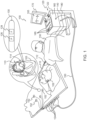
- FIG. 1 is an illustration of an example medical system 100 that is used to generate and display information during a medical procedure and to control the deployment of various catheters within a subject.
- Example system 100 includes a catheter 110, such as an intracardiac catheter, a console 120 and an associated catheter control unit 112.
- catheter 110 is used for diagnostic or therapeutic treatment, such as for example, mapping electrical potentials in a heart 103 of a patient 102 or performing an ablation procedure.
- catheter 110 can be used, mutatis mutandis, for other therapeutic and/or diagnostic purposes in heart 103, lungs, or in other body organs and ear, nose, and throat (ENT) procedures.
- ENT body organs and ear, nose, and throat
- An operator 130 can, for example, insert catheter 110 into the vascular system of patient 102 using catheter control unit 112 so that a distal end 114 of catheter 110 enters a chamber of the patient's heart 103.
- Console 210 can use magnetic position sensing to determine position coordinates of distal end 114 inside heart 103.
- a driver circuit 122 in console 120 may drive field generators 124 to generate magnetic fields within the body of patient 102.
- Field generators 124 can include coils that may be placed below the torso of the patient 103 at known positions external to patient 103. These coils may generate magnetic fields in a predefined working volume that contains heart 103.
- a location sensor 126 within distal end 114 of catheter 110 can generate electrical signals in response to these magnetic fields.
- a signal processor 140 can process these signals in order to determine the position coordinates of distal end 114, including both location and orientation coordinates.
- Known methods of position sensing described hereinabove are implemented in the CARTO TM mapping system produced by Biosense Webster Inc., of Diamond Bar, Calif., and is described in detail in the patents and the patent applications cited herein.
- Location sensor 126 is configured to transmit a signal to console 120 that is indicative of the location coordinates of distal end 114.
- Location sensor 126 can include one or more miniature coils, and typically can include multiple coils oriented along different axes.
- location sensor 126 can comprise either another type of magnetic sensor, or position transducers of other types, such as impedance-based or ultrasonic location sensors.
- Catheter 110 can also include a force sensor 128 contained within distal end 114.
- Force sensor 128 can measure a force applied by distal end 114 to the endocardial tissue of heart 103 and generate a signal that is sent to console 120.
- Force sensor 128 can include a magnetic field transmitter and a receiver connected by a spring in distal end 114, and can generate an indication of the force based on measuring a deflection of the spring. Further functional details of the catheter and force sensor are described in U.S. Patent Application Publications 2009/0093806 and 2009/0138007 .
- distal end 114 can include another type of force sensor that can use, for example, fiber optics or impedance measurements.
- Catheter 110 can include an electrode 130 coupled to distal end 114 and configured to function as an impedance-based position transducer. Additionally or alternatively, electrode 130 can be configured to measure a certain physiological property, for example the local surface electrical potential of the cardiac tissue at one or more of the multiple locations. Electrode 130 can be configured to apply radio frequency (RF) energy to ablate endocardial tissue in heart 103.
- RF radio frequency
- example medical system 100 can be configured to measure the position of distal end 114 using magnetic-based sensors
- other position tracking techniques can be used (e.g., impedance-based sensors).
- Magnetic position tracking techniques are described, for example, in U.S. Pat. Nos. 5,391,199 , 5,443,489 , 6,788,967 , 6,690,963 , 5,558,091 , 6,172,499 , and 6,177,792 .
- Impedance-based position tracking techniques are described, for example, in U.S. Pat. Nos. 5,983,126 , 6,456,864 and 5,944,022 .
- Signal processor 140 can be included in a general-purpose computer, with a suitable front end and interface circuits for receiving signals from catheter 110 and controlling the other components of console 120.
- Signal processor 140 can be programmed, using software, to carry out the functions that are described herein.
- the software can be downloaded to console 120 in electronic form, over a network, for example, or it can be provided on non-transitory tangible media, such as optical, magnetic or electronic memory media.
- some or all of the functions of signal processor 140 can be performed by dedicated or programmable digital hardware components.
- console 120 can also be connected by a cable 150 to external sensors 152.
- External sensors 152 can include body surface electrodes and/or position sensors that can be attached to the patient's skin using, for example, adhesive patches. The body surface electrodes can detect electrical impulses generated by the polarization and depolarization of cardiac tissue. The position sensors can use advanced catheter location and/or magnetic location sensors to locate catheter 110 during use.
- external sensors 152 can be embedded in a vest that is configured to be worn by patient 102. External sensors 152 can aid in identifying and tracking the respiration cycle of patient 103. External sensors 152 can transmit information to console 120 via cable 150.
- catheter 110, and external sensors 152 can communicate with console 120 and one another via a wireless interface.
- U.S. Pat. No. 6,266,551 describes, inter alia, a wireless catheter, which is not physically connected to signal processing and/or computing apparatus. Rather, a transmitter/receiver is attached to the proximal end of the catheter. The transmitter/receiver communicates with a signal processing and/or computer apparatus using wireless communication methods, such as infrared (IR), radio frequency (RF), wireless, Bluetooth ® , acoustic or other transmissions.
- IR infrared
- RF radio frequency
- Catheter 110 can be equipped with a wireless digital interface that can communicate with a corresponding input/output (I/O) interface 160 in console 120.
- Wireless digital interface and the I/O interface 160 can operate in accordance with any suitable wireless communication standard that is known in the art, such as IR, RF, Bluetooth, one of the IEEE 802.11 families of standards, or the HiperLAN standard.
- External sensors 152 can include one or more wireless sensor nodes integrated on a flexible substrate.
- the one or more wireless sensor nodes can include a wireless transmit/receive unit (WTRU) enabling local digital signal processing, a radio link, and a power supply such as miniaturized rechargeable battery.
- WTRU wireless transmit/receive unit
- Wireless digital interface and the I/O interface 160 can enable console 120 to interact with catheter 110 and external sensors 152. Based on the electrical impulses received from external sensors 152 and signals received from catheter 110 via wireless digital interface and the I/O interface 160 and other components of medical system 100, signal processor 140 can generate information 105 which can be shown on a display 170.
- signal processor 140 can present information 105, and/or can store data in a memory 180.
- Memory 180 can include any suitable volatile and/or non-volatile memory, such as random access memory or a hard disk drive.
- Catheter control unit 112 can be configured to be operated by an operator 130 to manipulate catheter 110 based on information 105, which is selectable using one or more input devices 185.
- medical system 100 can include a second operator that manipulates console 120 while operator 130 operates catheter control unit 112 to manipulate catheter 110 based on information 105.
- the second operator can also be provided with information 105.
- the mechanics of the construction and use of catheter control device 112 to move and position distal end 114 of catheter 110 is within the state of the art such as employed in the CARTO TM mapping system referenced above. For example, see also U.S. Patent No. 6,690,963 .
- a catheter 200 is shown in greater detail in FIG. 2 , showing some, but not all, of the elements that may be included in catheter 200.
- a catheter 200 may include, but is not limited to include, any one or more of the following components: electrode(s) 210; temperature sensor(s) 215; non-contact electrodes 220; image sensor(s) 225; positioning or location sensor(s) 230; distal tip 235; distal end 240; handle 245; and/or cable 250.
- the schematic diagram of catheter 200 in FIG. 3 is a high-level representation of possible components of catheter 200, such that the location and configuration of the components in catheter 200 may be different than shown.
- Distal end 240 of catheter 200 may include an electrode(s) 210 at distal tip 235 that may be used to measure electrical properties of the cardiac tissue. Electrode(s) 210 may also be used to send electrical signals to the heart for diagnostic purposes. Electrode(s) 210 may also perform ablation on defective cardiac tissue by applying energy (e.g., RF energy) directly to the cardiac tissue at the desired location of ablation.
- energy e.g., RF energy
- Distal end 240 of catheter 200 may include temperature sensor(s) 215 to measure the temperature of the cardiac tissue in contact with distal end 240 and/or measure the temperature of distal end 240 itself.
- temperature sensor(s) 215 to measure the temperature of the cardiac tissue in contact with distal end 240 and/or measure the temperature of distal end 240 itself.
- thermocouples or thermistors for measuring temperature may be placed anywhere along distal end 240 to serve as temperature sensor(s) 215.
- Distal end 240 may include non-contact electrodes 220 arranged in an array, which may be used to simultaneously receive and measure far-field electrical signals from the walls of the heart chamber of a patient. Electrode(s) 210 and non-contact electrodes 220 provide information regarding the electrical properties of the heart to processing device(s) for processing, such as for example, signal processor 140.
- Catheter(s) 200 may be equipped with one or more image sensor(s) 225, such as a charge coupled device (CCD) image sensor, and/or a camera for capturing endoscopic images when inserted in a body cavity.
- Image sensor(s) 225 may be located at distal end 240.
- Distal end 240 may include location sensor(s) 230 in distal tip 235 of catheter 200 that may generate signals used to determine the position and orientation (and/or distance) of catheter 200 in the body.
- the relative position and orientation of location sensor(s) 230, electrode(s) 210, and distal tip 235 are fixed and known in order to facilitate accurate positioning information of distal tip 235.
- the position of location sensor(s) 230 may be determined in part based on the relative position to known positions outside the heart (e.g., based on extra-cardiac sensors).
- the use of location sensor(s) 230 may provide improved location accuracy within the magnetic fields in the surrounding space and provide location information that is adaptable to patient movement because the position information of catheter 200 is relative to the anatomy of the patient.
- Handle 245 of catheter 220 may be operated by an operator such as a physician and may include controls 250 to enable the physician to effectively steer distal tip 235 in the desired direction.
- Electrodes 210, 220, and sensors 215, 225, 230 may be connected to processing device(s), such as for example signal processor 140, via wires that may pass through handle 245 and cable 250, in order to provide information, such as location, electrical, imaging and/or temperature information, to a console system, which may be used to operate and display the function of catheter 200 within the heart in real-time.
- processing device(s) such as for example signal processor 140
- wires may pass through handle 245 and cable 250
- information such as location, electrical, imaging and/or temperature information
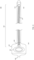
- FIG. 3 is a schematic diagram of an example catheter 300 with a printed flexible substrate 310 in accordance with certain implementations.
- Catheter 300 includes a catheter shaft 305, a handle 340 and a cable 360.
- Catheter shaft 305 includes a distal end 320 and a proximate end or handle end 330.
- Distal end 320 includes a number of sensors (not shown) as described herein.
- Proximate end 330 ends at handle 340.
- Handle 340 includes controls 350 and a cable 360 which connects to processing devices in a console, for example, console 120.
- Printed flexible substrate 310 includes distal end connectors 370 and proximate end connectors 380.
- Printed flexible substrate 310 extends from distal end 320 to proximate end 330.
- distal end connectors 370 are connected to sensors and proximate end connectors 380 are connected to cable 360 via cards or connectors in handle 340.
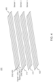
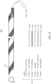
- FIG. 4 is an example printed flexible substrate 400 in accordance with certain implementations.
- Printed flexible substrate 400 can be any type of flexible substrate including a flexible printed circuit board (PCB), a ribbon and other similar structures.
- Printed flexible substrate 400 can include a predetermined number of layers which may depend on the type of sensor in the catheter.
- the predetermined number of layers can include signal layers and reference layers.
- the sensor can be a location sensor which includes three coils, one for each of an X, Y and Z axis.
- signal layers can include layers 410, 415 and 420, which are associated with coils representing each X, Y and Z axis.
- a reference layer e.g., layer 405, is used for magnetic interference cancellation that results from other devices in the catheter or the medical system.
- each of layers 405, 410, 415, and 420 can include any number of traces.
- the traces may include signal traces and ground traces.
- the traces can include ground traces 430 and 432, a first signal trace 434 and a second signal trace 436.
- Each of the traces e.g., ground traces 430 and 432, first signal trace 434 and second signal trace 436, is made of a conductive material, such as copper, gold, gold cladded copper or other similar materials.
- the conductive material is deposited, printed or otherwise positioned on the flexible substrate. Measurements from each of layers 405, 410, 415, and 420 are eventually routed to processing device(s) such as for example signal processor 140 and signal processing hardware such as amplifiers and filters.
- reference layer 405 is configured to measure magnetic radiation that may cause interference in the measurements carried by first signal trace 434 and second signal trace 436 and in the respective signal layers in layers 410, 415 and 420.
- Reference layer 405 is shorted and measures the magnetic fields that cause the magnetic interference. This information may then be used by processing device(s) such as for example signal processor 140 and signal processing hardware to cancel out the magnetic interference from the measurements carried by the signal layers, e.g., layers 410, 415 and 420.
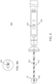
- FIG. 5 is an example printed flexible substrate 550 wrapped with respect to a catheter 500 in accordance with certain implementations.
- Catheter 500 can include a catheter shaft 510 and a handle 520.
- Catheter shaft 510 includes a distal tip 530 which includes a sensor 540 as shown in FIG. 5A .
- Handle 520 includes an electronic card 525, which may include filters, signal amplifiers, and analog-to-digital converters for signal processing.
- a printed flexible substrate 550 can be implemented as shown in FIG. 4 and then wrapped around a catheter shaft 510.
- One end of printed flexible substrate 550 is connected to sensor 540 and another end of printed flexible substrate 550 is connected to electronic card 525.
- a printed flexible substrate 550 can be wrapped around an irrigation tube, for example, inside of catheter shaft 510 for sensors that do not use magnetic based devices.
- FIG. 6A shows more detail for the configuration illustrated in FIG. 5 and FIG. 6B shows a cross-section of the configuration shown in FIG. 6A.
- FIG. 6A shows a catheter shaft 600 that has a printed flexible substrate 610 wrapped with respect to catheter shaft 600 in accordance with certain implementations.
- Printed flexible substrate 610 includes multiple layers 615 1 - 615 N , which carry signals from the sensors to the processing device(s).
- a shaft cross section 620 shows the layer structures where an inner layer 622 is built with isolation material.
- Conductor layers (i.e. printed flexible substrate) 610 is printed and isolated from a shielding layer 626 by an isolation layer 624.
- the shielding layer 626 is isolated by a nonconductive layer 628.
- the printed conductors/traces are applied in a spiral shape to enable flexibility of the shaft 600.
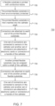
- FIG. 7 is a method 700 for assembling a catheter in accordance with certain implementations.
- a flexible substrate is printed with conductive traces (705). Each printed flexible substrate can include multiple layers or levels.
- the printed flexible substrate is then environmentally protected (710). For example, the printed flexible substrate can be laminated.
- the printed flexible substrate is then inserted into the catheter shaft (715).
- Connectors are attached to each end of the printed flexible substrate (720). One set of connectors are connected to sensors in the catheter and another set of connectors are attached to electronic cards or connectors in a handle of the catheter (725).
- another printed flexible substrate may be wrapped with respect to a shaft of the catheter (730). Connectors are attached to each end of the another printed flexible substrate (735). One set of connectors are connected to sensors in the catheter and another set of connectors are attached to electronic cards or connectors in a handle of the catheter (740).
- a method for catheter assembly includes printing conductive traces on at least one flexible substrate, encapsulating the at least one flexible substrate for environmental protection, inserting at least one encapsulated flexible substrate into a catheter shaft of a catheter, attaching connectors to each end of the at least one encapsulated flexible substrate, attaching a set of connectors to sensors located at a distal end of the catheter, and attaching another set of connectors to electronics in a handle of the catheter.
- the method includes wrapping an encapsulated flexible substrate around a component contained within the catheter shaft, attaching connectors to each end of the encapsulated flexible substrate, attaching a set of connectors to non-magnetic based sensors in the catheter, and attaching another set of connectors to electronics in a handle of the catheter.
- the at least one flexible substrate includes a plurality of layers, each layer having a plurality of conductive traces.
- the plurality of layers includes a reference layer, and the method further includes shorting two of the plurality of conductive traces in the reference layer to measure magnetic radiation for interference cancellation determination.
- the plurality of layers includes signal layers that are connected to the sensors.
- the encapsulating step includes at least laminating the at least one flexible substrate.
- the at least one encapsulated flexible substrate is rolled prior to insertion into the catheter shaft. In an implementation, the at least one encapsulated flexible substrate is inserted substantially linear into the catheter shaft. In an implementation, the conductive traces include signal traces and ground traces.
- a catheter in general, includes a catheter shaft having a distal end and a handle.
- the catheter further includes sensors located at the distal end, electronics located at the handle and at least one flexible substrate which is inserted inside the catheter shaft, where the at least one flexible substrate has conductive traces.
- the catheter further includes first connectors which connect the sensors to one end of the at least one flexible substrate and second connectors which connect the electronics to another end of the at least one flexible substrate. The first connectors and the second connectors are connected after insertion into the catheter shaft.
- the at least one flexible substrate is encapsulated for environmental protection.
- the catheter further includes non-magnetic sensors, another flexible substrate that is wrapped around a component in the catheter shaft, third connectors which connect the non-magnetic sensors to one end of the another flexible substrate and fourth connectors which connect the electronics to another end of the flexible substrate.
- the at least one flexible substrate includes a plurality of layers, each layer having a plurality of conductive traces.
- the plurality of layers includes a reference layer, where two of the plurality of conductive traces are shorted in the reference layer to measure magnetic radiation for interference cancellation determination.
- the plurality of layers includes signal layers that are connected to the sensors.
- the at least one flexible substrate is laminated for environmental protection.
- the at least one flexible substrate is rolled prior to insertion into the catheter shaft.
- the at least one flexible substrate is positioned substantially linear into the catheter shaft.
- the conductive traces include signal traces and ground traces.
- cardiac mapping and ablation procedures for a cardiac system, although it is understood by one skilled in the art that the disclosures may be applied to systems and procedures that can be used in any cavity or system in the body, including, but not limited to, the respiratory/pulmonary system, the respiratory and pulmonary system, the digestive system, the neurovascular system, and/or the circulatory system.
- Examples of computer-readable storage media include, but are not limited to, a read only memory (ROM), a random access memory (RAM), a register, cache memory, semiconductor memory devices, magnetic media such as internal hard disks and removable disks, magneto-optical media, and optical media such as CD-ROM disks, and digital versatile disks (DVDs).
- ROM read only memory
- RAM random access memory
- register cache memory
- semiconductor memory devices magnetic media such as internal hard disks and removable disks, magneto-optical media, and optical media such as CD-ROM disks, and digital versatile disks (DVDs).
Landscapes
- Health & Medical Sciences (AREA)
- Life Sciences & Earth Sciences (AREA)
- Engineering & Computer Science (AREA)
- Surgery (AREA)
- Veterinary Medicine (AREA)
- Biomedical Technology (AREA)
- Heart & Thoracic Surgery (AREA)
- Animal Behavior & Ethology (AREA)
- General Health & Medical Sciences (AREA)
- Public Health (AREA)
- Medical Informatics (AREA)
- Molecular Biology (AREA)
- Physics & Mathematics (AREA)
- Biophysics (AREA)
- Pathology (AREA)
- Cardiology (AREA)
- Human Computer Interaction (AREA)
- Manufacturing & Machinery (AREA)
- Plasma & Fusion (AREA)
- Nuclear Medicine, Radiotherapy & Molecular Imaging (AREA)
- Otolaryngology (AREA)
- Microelectronics & Electronic Packaging (AREA)
- Hematology (AREA)
- Anesthesiology (AREA)
- Pulmonology (AREA)
- Physiology (AREA)
- Media Introduction/Drainage Providing Device (AREA)
- Surgical Instruments (AREA)
- Measurement And Recording Of Electrical Phenomena And Electrical Characteristics Of The Living Body (AREA)
Claims (15)
- Verfahren zum Zusammenbauen eines Katheters, das Verfahren umfassend:Drucken von leitfähigen Spuren auf mindestens ein flexibles Substrat;Einkapseln des mindestens einen flexiblen Substrats (310) zum Schutz vor der Umgebung, wobei das mindestens eine flexible Substrat eine Vielzahl von Schichten einschließt, wobei jede Schicht eine Vielzahl von leitfähigen Spuren aufweist und die Vielzahl von Schichten eine Referenzschicht (405) einschließt, das Verfahren ferner umfassend:Kurzschließen von zwei der Vielzahl von leitfähigen Spuren in der Referenz Schicht zum Ermöglichen einer Messung der magnetischen Strahlung für die Bestimmung der Interferenzunterdrückung;Einführen mindestens eines eingekapselten flexiblen Substrats in einen Katheterschaft (305) eines Katheters (300);Anbringen von Verbindern (370, 380) an jedem Ende des mindestens einen eingekapselten flexiblen Substrats, wobei;ein Satz der Verbinder (370) ebenso mit Sensoren verbunden ist, die sich an einem distalen Ende des Katheters befinden; undein weiterer Satz von Verbindern (380) ebenso mit der Elektronik in einem Griff (340) verbunden ist, der sich an einem proximalen Ende des Katheters befindet.
- Verfahren nach Anspruch 1, ferner umfassend:Wickeln eines zweiten eingekapselten flexiblen Substrats um eine Komponente, die in dem Katheterschaft enthalten ist;Anbringen von Verbindern an jedem Ende des zweiten eingekapselten flexiblen Substrats, wobei;ein Satz der Verbinder ebenso mit nichtmagnetischbasierten Sensoren verbunden ist, die sich an einem distalen Ende in dem Katheter befinden; undein weiterer Satz der Verbinder ebenso mit der Elektronik in einem Griff verbunden ist, der sich an dem proximalen Ende des Katheters befindet.
- Verfahren nach Anspruch 1, wobei die Vielzahl von Schichten Signalschichten (410, 415, 420) einschließt, die mit den Sensoren verbunden sind.
- Verfahren nach Anspruch 1, wobei das Einkapseln mindestens das Laminieren des mindestens einen flexiblen Substrats einschließt.
- Verfahren nach Anspruch 1, wobei das mindestens eine eingekapselte flexible Substrat vor dem Einführen in den Katheterschaft gerollt wird.
- Verfahren nach Anspruch 1, wobei das mindestens eine eingekapselte flexible Substrat im Wesentlichen linear in den Katheterschaft eingeführt wird.
- Verfahren nach Anspruch 1, wobei die leitfähigen Spuren Signalspuren (434, 436) und Erdungsspuren (430, 432) einschließen.
- Katheter, umfassend:einen Katheterschaft, der ein distales Ende und einen Griff aufweist;Sensoren, die sich an dem distalen Ende befinden;Elektronik, die sich an dem Griff befindet;mindestens ein flexibles Substrat, das ins Innere des Katheterschaft eingeführt ist, wobei das mindestens eine flexible Substrat leitfähige Spuren aufweist, wobei das mindestens eine flexible Substrat Folgendes einschließt;eine Vielzahl von Schichten, wobei jede Schicht eine Vielzahl von leitenden Spuren aufweist, wobei die Vielzahl von Schichten eine Referenzschicht einschließt, wobei zwei der Vielzahl von leitfähigen Spuren in der Referenzschicht kurzgeschlossen sind, zum Ermöglichen der Messung der magnetischen Strahlung für die Bestimmung der Interferenzunterdrückung;erste Verbinder, wobei die ersten Verbinder die Sensoren mit einem Ende des mindestens einen flexiblen Substrats verbinden; undzweite Verbinder, wobei die zweiten Verbinder die Elektronik mit einem anderen Ende des mindestens einen flexiblen Substrats verbinden,wobei der erste Verbinder und der zweite Verbinder nach der Einführung in den Katheterschaft verbunden werden.
- Katheter nach Anspruch 8, wobei das mindestens eine flexible Substrat zum Schutz vor der Umgebung eingekapselt ist.
- Katheter nach Anspruch 8, ferner umfassend:nichtmagnetische Sensoren;ein weiteres flexibles Substrat, das um eine Komponente in dem Katheterschaft gewickelt ist;dritte Verbinder, wobei die dritten Verbinder die nichtmagnetischen Sensoren mit einem Ende des anderen flexiblen Substrats verbinden; undvierte Verbinder, wobei die vierten Verbinder die Elektronik mit einem anderen Ende des anderen flexiblen Substrats verbinden.
- Katheter nach Anspruch 8, wobei die Vielzahl von Schichten Signalschichten einschließt, die mit den Sensoren verbunden sind.
- Katheter nach Anspruch 8, wobei das mindestens eine flexible Substrat zum Schutz vor der Umgebung laminiert ist.
- Katheter nach Anspruch 8, wobei das mindestens eine flexible Substrat vor dem Einführen in den Katheterschaft gerollt wird.
- Katheter nach Anspruch 8, wobei das mindestens eine flexible Substrat im Wesentlichen linear in dem Katheterschaft positioniert ist.
- Katheter nach Anspruch 8, wobei die leitfähigen Spuren Signalspuren und Erdungsspuren einschließen.
Priority Applications (1)
| Application Number | Priority Date | Filing Date | Title |
|---|---|---|---|
| EP24209809.3A EP4478843A3 (de) | 2017-12-07 | 2018-11-14 | Katheter und verfahren für eine katheteranordnung |
Applications Claiming Priority (2)
| Application Number | Priority Date | Filing Date | Title |
|---|---|---|---|
| US15/834,623 US11700695B2 (en) | 2017-12-07 | 2017-12-07 | Using encapsulated flexible substrate to link sensors and electronics in a catheter assembly |
| PCT/IB2018/058958 WO2019111078A1 (en) | 2017-12-07 | 2018-11-14 | Catheter and method for catheter assembly |
Related Child Applications (1)
| Application Number | Title | Priority Date | Filing Date |
|---|---|---|---|
| EP24209809.3A Division EP4478843A3 (de) | 2017-12-07 | 2018-11-14 | Katheter und verfahren für eine katheteranordnung |
Publications (3)
| Publication Number | Publication Date |
|---|---|
| EP3720378A1 EP3720378A1 (de) | 2020-10-14 |
| EP3720378C0 EP3720378C0 (de) | 2024-11-06 |
| EP3720378B1 true EP3720378B1 (de) | 2024-11-06 |
Family
ID=64664800
Family Applications (2)
| Application Number | Title | Priority Date | Filing Date |
|---|---|---|---|
| EP24209809.3A Pending EP4478843A3 (de) | 2017-12-07 | 2018-11-14 | Katheter und verfahren für eine katheteranordnung |
| EP18819211.6A Active EP3720378B1 (de) | 2017-12-07 | 2018-11-14 | Katheter und verfahren zur katheteranordnung |
Family Applications Before (1)
| Application Number | Title | Priority Date | Filing Date |
|---|---|---|---|
| EP24209809.3A Pending EP4478843A3 (de) | 2017-12-07 | 2018-11-14 | Katheter und verfahren für eine katheteranordnung |
Country Status (6)
| Country | Link |
|---|---|
| US (3) | US11700695B2 (de) |
| EP (2) | EP4478843A3 (de) |
| JP (1) | JP2021505269A (de) |
| CN (1) | CN111511303B (de) |
| IL (1) | IL275087B2 (de) |
| WO (1) | WO2019111078A1 (de) |
Families Citing this family (11)
| Publication number | Priority date | Publication date | Assignee | Title |
|---|---|---|---|---|
| US11700695B2 (en) | 2017-12-07 | 2023-07-11 | Biosense Webster (Israel) Ltd. | Using encapsulated flexible substrate to link sensors and electronics in a catheter assembly |
| CN111683589B (zh) * | 2018-02-05 | 2024-05-10 | 迈迪瑞股份公司 | 具有导管和传感器的设备 |
| EP3791783A1 (de) * | 2019-09-10 | 2021-03-17 | Carl Freudenberg KG | Katheter mit dehnbarer leiterplatte |
| EP3791782B8 (de) * | 2019-09-10 | 2023-09-06 | Carl Freudenberg KG | Katheter mit flexibler leiterplatte und fertigungsverfahren für flexible leiterplatte |
| US11344221B2 (en) * | 2019-09-16 | 2022-05-31 | Biosense Webster (Israel) Ltd. | Flexible shielded position sensor |
| US11812957B2 (en) * | 2019-12-30 | 2023-11-14 | Cilag Gmbh International | Surgical instrument comprising a signal interference resolution system |
| DE102020120894A1 (de) | 2020-08-07 | 2022-02-10 | Innome Gmbh | Katheter |
| WO2022157270A1 (en) * | 2021-01-20 | 2022-07-28 | Sensome | Insertable device including flexible circuitry |
| US20240215893A1 (en) * | 2022-12-30 | 2024-07-04 | Biosense Webster (Israel) Ltd. | Double-sided encapsulated planar catheter |
| CN120583909A (zh) * | 2023-01-12 | 2025-09-02 | 马格尼司帝有限公司 | 用于长形介入装置的摄像头模块和柔性电路板 |
| CN121511109A (zh) * | 2023-07-13 | 2026-02-10 | 耐普罗有限公司 | 基于印刷电子器件的导管 |
Citations (1)
| Publication number | Priority date | Publication date | Assignee | Title |
|---|---|---|---|---|
| US20110295110A1 (en) * | 2009-02-11 | 2011-12-01 | Koninklijke Philips Electronics N.V. | Method and system of tracking and mapping in a medical procedure |
Family Cites Families (36)
| Publication number | Priority date | Publication date | Assignee | Title |
|---|---|---|---|---|
| US5588432A (en) | 1988-03-21 | 1996-12-31 | Boston Scientific Corporation | Catheters for imaging, sensing electrical potentials, and ablating tissue |
| US5391199A (en) | 1993-07-20 | 1995-02-21 | Biosense, Inc. | Apparatus and method for treating cardiac arrhythmias |
| US5558091A (en) | 1993-10-06 | 1996-09-24 | Biosense, Inc. | Magnetic determination of position and orientation |
| US5876336A (en) | 1994-10-11 | 1999-03-02 | Ep Technologies, Inc. | Systems and methods for guiding movable electrode elements within multiple-electrode structure |
| US6690963B2 (en) | 1995-01-24 | 2004-02-10 | Biosense, Inc. | System for determining the location and orientation of an invasive medical instrument |
| US5697377A (en) | 1995-11-22 | 1997-12-16 | Medtronic, Inc. | Catheter mapping system and method |
| WO1997029678A2 (en) | 1996-02-15 | 1997-08-21 | Biosense Inc. | Catheter calibration and usage monitoring system |
| US6177792B1 (en) | 1996-03-26 | 2001-01-23 | Bisense, Inc. | Mutual induction correction for radiator coils of an objects tracking system |
| US5944022A (en) | 1997-04-28 | 1999-08-31 | American Cardiac Ablation Co. Inc. | Catheter positioning system |
| US6172499B1 (en) | 1999-10-29 | 2001-01-09 | Ascension Technology Corporation | Eddy current error-reduced AC magnetic position measurement system |
| US6546270B1 (en) | 2000-07-07 | 2003-04-08 | Biosense, Inc. | Multi-electrode catheter, system and method |
| CN100379576C (zh) | 2002-10-30 | 2008-04-09 | 因弗内斯医疗有限公司 | 生产电化学传感器的连续过程中酶的印刷湿化 |
| US8147486B2 (en) | 2003-09-22 | 2012-04-03 | St. Jude Medical, Atrial Fibrillation Division, Inc. | Medical device with flexible printed circuit |
| JP4426430B2 (ja) * | 2004-12-15 | 2010-03-03 | 日東電工株式会社 | カテーテル及びその製造方法 |
| US7860553B2 (en) * | 2006-02-09 | 2010-12-28 | Biosense Webster, Inc. | Two-stage calibration of medical probes |
| US20090024015A1 (en) * | 2007-07-17 | 2009-01-22 | Edwards Lifesciences Corporation | Sensing element having an adhesive backing |
| US8357152B2 (en) | 2007-10-08 | 2013-01-22 | Biosense Webster (Israel), Ltd. | Catheter with pressure sensing |
| US8535308B2 (en) | 2007-10-08 | 2013-09-17 | Biosense Webster (Israel), Ltd. | High-sensitivity pressure-sensing probe |
| WO2010027957A2 (en) * | 2008-09-03 | 2010-03-11 | Keimar, Inc. | Systems for characterizing physiologic parameters and methods for use therewith |
| EP2552528B1 (de) | 2010-03-26 | 2020-08-05 | Flip Technologies Limited | Verfahren zur herstellung eines katheters |
| US8560086B2 (en) * | 2010-12-02 | 2013-10-15 | St. Jude Medical, Atrial Fibrillation Division, Inc. | Catheter electrode assemblies and methods of construction therefor |
| US9226386B2 (en) * | 2012-07-13 | 2015-12-29 | Stmicroelectronics S.R.L. | Printed circuit board with reduced emission of electro-magnetic radiation |
| EP2934334A4 (de) * | 2012-12-20 | 2016-09-07 | Jeremy Stigall | Katheteranordnung mit verkürzter spitze |
| EP3777703B1 (de) | 2013-02-08 | 2023-04-05 | Acutus Medical Inc. | Expandierbare katheteranordnung mit einer flexiblen leiterplatte |
| US20140276004A1 (en) * | 2013-03-15 | 2014-09-18 | Medtronic Navigation, Inc. | Navigated Surgical Instrument |
| US20150197063A1 (en) * | 2014-01-12 | 2015-07-16 | Zohar SHINAR | Device, method, and system of three-dimensional printing |
| CN105939662B (zh) * | 2014-01-28 | 2019-02-15 | 圣犹达医疗用品国际控股有限公司 | 具有封装电子组件的医疗设备及其制造方法 |
| WO2015116687A1 (en) | 2014-01-28 | 2015-08-06 | St. Jude Medical, Cardiology Division, Inc. | Elongate medical devices incorporating a flexible substrate, a sensor, and electrically-conductive traces |
| EP3424453B1 (de) * | 2014-02-04 | 2026-04-01 | Boston Scientific Scimed, Inc. | Alternative platzierung von thermischen sensoren auf bipolarer elektrode |
| EP3191164A4 (de) * | 2014-09-12 | 2018-08-15 | X-Rhythm, LLC | Mehrelektrodenabbildungssystem |
| US10758302B2 (en) * | 2014-11-11 | 2020-09-01 | Biosense Webster (Israel) Ltd. | Irrigated ablation catheter with sensor array |
| US20160228061A1 (en) * | 2015-02-10 | 2016-08-11 | Cathprint Ab | Low profile medical device with integrated flexible circuit and methods of making the same |
| EP4382044A3 (de) | 2015-02-10 | 2024-08-14 | Cathprint AB | Medizinische vorrichtung mit flachem profil mit integrierter flexibler schaltung und verfahren zur herstellung davon |
| US10363090B2 (en) | 2016-01-05 | 2019-07-30 | Biosense Webster (Israel) Ltd. | Catheter with flow diverter and force sensor |
| CN106606372A (zh) * | 2016-08-30 | 2017-05-03 | 四川锦江电子科技有限公司 | 一种多电极导管三维定位方法,及其装置 |
| US11700695B2 (en) * | 2017-12-07 | 2023-07-11 | Biosense Webster (Israel) Ltd. | Using encapsulated flexible substrate to link sensors and electronics in a catheter assembly |
-
2017
- 2017-12-07 US US15/834,623 patent/US11700695B2/en active Active
-
2018
- 2018-11-14 JP JP2020530962A patent/JP2021505269A/ja active Pending
- 2018-11-14 CN CN201880078976.7A patent/CN111511303B/zh active Active
- 2018-11-14 EP EP24209809.3A patent/EP4478843A3/de active Pending
- 2018-11-14 EP EP18819211.6A patent/EP3720378B1/de active Active
- 2018-11-14 WO PCT/IB2018/058958 patent/WO2019111078A1/en not_active Ceased
- 2018-11-14 IL IL275087A patent/IL275087B2/en unknown
-
2022
- 2022-07-28 US US17/876,191 patent/US12185473B2/en active Active
-
2024
- 2024-12-19 US US18/988,008 patent/US20250120019A1/en active Pending
Patent Citations (1)
| Publication number | Priority date | Publication date | Assignee | Title |
|---|---|---|---|---|
| US20110295110A1 (en) * | 2009-02-11 | 2011-12-01 | Koninklijke Philips Electronics N.V. | Method and system of tracking and mapping in a medical procedure |
Also Published As
| Publication number | Publication date |
|---|---|
| US20220369472A1 (en) | 2022-11-17 |
| EP3720378C0 (de) | 2024-11-06 |
| EP4478843A3 (de) | 2025-03-12 |
| WO2019111078A1 (en) | 2019-06-13 |
| EP4478843A2 (de) | 2024-12-18 |
| JP2021505269A (ja) | 2021-02-18 |
| US20190175056A1 (en) | 2019-06-13 |
| IL275087B2 (en) | 2024-08-01 |
| EP3720378A1 (de) | 2020-10-14 |
| CN111511303A (zh) | 2020-08-07 |
| IL275087B1 (en) | 2024-04-01 |
| US11700695B2 (en) | 2023-07-11 |
| CN111511303B (zh) | 2024-07-19 |
| IL275087A (en) | 2020-07-30 |
| US12185473B2 (en) | 2024-12-31 |
| US20250120019A1 (en) | 2025-04-10 |
Similar Documents
| Publication | Publication Date | Title |
|---|---|---|
| US12185473B2 (en) | Catheter with flexible substrate for minimizing magnetic interference | |
| US20250082220A1 (en) | Catheter splines with embedded circuit elements | |
| EP3689232B1 (de) | Doppelfunktionssensoren für einen korbkatheter | |
| CA2666243C (en) | Esophageal mapping catheter | |
| JP2018143771A (ja) | 小型化力センサ | |
| JP2017086913A (ja) | 4つのコイルを有する対称性の短い接触力センサ | |
| CN106687168A (zh) | 多电极标测导管 | |
| EP3878390B1 (de) | System zur lückendetektion in ablationslinien | |
| JP2018198981A (ja) | 形状記憶を備えたドングル | |
| EP3320944A1 (de) | Multielektrodenkatheter zur verhinderung einer physiologischen fluidstromeinschränkung | |
| JP7536638B2 (ja) | カテーテルのための多目的検知及び高周波(rf)アブレーション渦巻き型電極 | |
| US12082875B2 (en) | Balloon catheter having a coil for sensing tissue temperature and position of the balloon |
Legal Events
| Date | Code | Title | Description |
|---|---|---|---|
| STAA | Information on the status of an ep patent application or granted ep patent |
Free format text: STATUS: UNKNOWN |
|
| STAA | Information on the status of an ep patent application or granted ep patent |
Free format text: STATUS: THE INTERNATIONAL PUBLICATION HAS BEEN MADE |
|
| PUAI | Public reference made under article 153(3) epc to a published international application that has entered the european phase |
Free format text: ORIGINAL CODE: 0009012 |
|
| STAA | Information on the status of an ep patent application or granted ep patent |
Free format text: STATUS: REQUEST FOR EXAMINATION WAS MADE |
|
| 17P | Request for examination filed |
Effective date: 20200520 |
|
| AK | Designated contracting states |
Kind code of ref document: A1 Designated state(s): AL AT BE BG CH CY CZ DE DK EE ES FI FR GB GR HR HU IE IS IT LI LT LU LV MC MK MT NL NO PL PT RO RS SE SI SK SM TR |
|
| AX | Request for extension of the european patent |
Extension state: BA ME |
|
| DAV | Request for validation of the european patent (deleted) | ||
| DAX | Request for extension of the european patent (deleted) | ||
| RAP3 | Party data changed (applicant data changed or rights of an application transferred) |
Owner name: BIOSENSE WEBSTER (ISRAEL) LTD. |
|
| GRAP | Despatch of communication of intention to grant a patent |
Free format text: ORIGINAL CODE: EPIDOSNIGR1 |
|
| STAA | Information on the status of an ep patent application or granted ep patent |
Free format text: STATUS: GRANT OF PATENT IS INTENDED |
|
| INTG | Intention to grant announced |
Effective date: 20240109 |
|
| GRAJ | Information related to disapproval of communication of intention to grant by the applicant or resumption of examination proceedings by the epo deleted |
Free format text: ORIGINAL CODE: EPIDOSDIGR1 |
|
| STAA | Information on the status of an ep patent application or granted ep patent |
Free format text: STATUS: REQUEST FOR EXAMINATION WAS MADE |
|
| INTC | Intention to grant announced (deleted) | ||
| GRAP | Despatch of communication of intention to grant a patent |
Free format text: ORIGINAL CODE: EPIDOSNIGR1 |
|
| STAA | Information on the status of an ep patent application or granted ep patent |
Free format text: STATUS: GRANT OF PATENT IS INTENDED |
|
| INTG | Intention to grant announced |
Effective date: 20240611 |
|
| GRAS | Grant fee paid |
Free format text: ORIGINAL CODE: EPIDOSNIGR3 |
|
| GRAA | (expected) grant |
Free format text: ORIGINAL CODE: 0009210 |
|
| STAA | Information on the status of an ep patent application or granted ep patent |
Free format text: STATUS: THE PATENT HAS BEEN GRANTED |
|
| AK | Designated contracting states |
Kind code of ref document: B1 Designated state(s): AL AT BE BG CH CY CZ DE DK EE ES FI FR GB GR HR HU IE IS IT LI LT LU LV MC MK MT NL NO PL PT RO RS SE SI SK SM TR |
|
| REG | Reference to a national code |
Ref country code: GB Ref legal event code: FG4D |
|
| REG | Reference to a national code |
Ref country code: CH Ref legal event code: EP |
|
| REG | Reference to a national code |
Ref country code: DE Ref legal event code: R096 Ref document number: 602018076331 Country of ref document: DE |
|
| REG | Reference to a national code |
Ref country code: IE Ref legal event code: FG4D |
|
| U01 | Request for unitary effect filed |
Effective date: 20241127 |
|
| U07 | Unitary effect registered |
Designated state(s): AT BE BG DE DK EE FI FR IT LT LU LV MT NL PT RO SE SI Effective date: 20241204 |
|
| U20 | Renewal fee for the european patent with unitary effect paid |
Year of fee payment: 7 Effective date: 20241209 |
|
| PG25 | Lapsed in a contracting state [announced via postgrant information from national office to epo] |
Ref country code: IS Free format text: LAPSE BECAUSE OF FAILURE TO SUBMIT A TRANSLATION OF THE DESCRIPTION OR TO PAY THE FEE WITHIN THE PRESCRIBED TIME-LIMIT Effective date: 20250306 Ref country code: HR Free format text: LAPSE BECAUSE OF FAILURE TO SUBMIT A TRANSLATION OF THE DESCRIPTION OR TO PAY THE FEE WITHIN THE PRESCRIBED TIME-LIMIT Effective date: 20241106 |
|
| PG25 | Lapsed in a contracting state [announced via postgrant information from national office to epo] |
Ref country code: ES Free format text: LAPSE BECAUSE OF FAILURE TO SUBMIT A TRANSLATION OF THE DESCRIPTION OR TO PAY THE FEE WITHIN THE PRESCRIBED TIME-LIMIT Effective date: 20241106 |
|
| PG25 | Lapsed in a contracting state [announced via postgrant information from national office to epo] |
Ref country code: NO Free format text: LAPSE BECAUSE OF FAILURE TO SUBMIT A TRANSLATION OF THE DESCRIPTION OR TO PAY THE FEE WITHIN THE PRESCRIBED TIME-LIMIT Effective date: 20250206 |
|
| PG25 | Lapsed in a contracting state [announced via postgrant information from national office to epo] |
Ref country code: GR Free format text: LAPSE BECAUSE OF FAILURE TO SUBMIT A TRANSLATION OF THE DESCRIPTION OR TO PAY THE FEE WITHIN THE PRESCRIBED TIME-LIMIT Effective date: 20250207 |
|
| PG25 | Lapsed in a contracting state [announced via postgrant information from national office to epo] |
Ref country code: PL Free format text: LAPSE BECAUSE OF FAILURE TO SUBMIT A TRANSLATION OF THE DESCRIPTION OR TO PAY THE FEE WITHIN THE PRESCRIBED TIME-LIMIT Effective date: 20241106 |
|
| PG25 | Lapsed in a contracting state [announced via postgrant information from national office to epo] |
Ref country code: RS Free format text: LAPSE BECAUSE OF FAILURE TO SUBMIT A TRANSLATION OF THE DESCRIPTION OR TO PAY THE FEE WITHIN THE PRESCRIBED TIME-LIMIT Effective date: 20250206 |
|
| REG | Reference to a national code |
Ref country code: CH Ref legal event code: PL |
|
| PG25 | Lapsed in a contracting state [announced via postgrant information from national office to epo] |
Ref country code: SM Free format text: LAPSE BECAUSE OF FAILURE TO SUBMIT A TRANSLATION OF THE DESCRIPTION OR TO PAY THE FEE WITHIN THE PRESCRIBED TIME-LIMIT Effective date: 20241106 |
|
| REG | Reference to a national code |
Ref country code: CH Ref legal event code: PL |
|
| PG25 | Lapsed in a contracting state [announced via postgrant information from national office to epo] |
Ref country code: CH Free format text: LAPSE BECAUSE OF NON-PAYMENT OF DUE FEES Effective date: 20241130 |
|
| PG25 | Lapsed in a contracting state [announced via postgrant information from national office to epo] |
Ref country code: SK Free format text: LAPSE BECAUSE OF FAILURE TO SUBMIT A TRANSLATION OF THE DESCRIPTION OR TO PAY THE FEE WITHIN THE PRESCRIBED TIME-LIMIT Effective date: 20241106 |
|
| PG25 | Lapsed in a contracting state [announced via postgrant information from national office to epo] |
Ref country code: CZ Free format text: LAPSE BECAUSE OF FAILURE TO SUBMIT A TRANSLATION OF THE DESCRIPTION OR TO PAY THE FEE WITHIN THE PRESCRIBED TIME-LIMIT Effective date: 20241106 |
|
| PLBE | No opposition filed within time limit |
Free format text: ORIGINAL CODE: 0009261 |
|
| STAA | Information on the status of an ep patent application or granted ep patent |
Free format text: STATUS: NO OPPOSITION FILED WITHIN TIME LIMIT |
|
| PG25 | Lapsed in a contracting state [announced via postgrant information from national office to epo] |
Ref country code: MC Free format text: LAPSE BECAUSE OF FAILURE TO SUBMIT A TRANSLATION OF THE DESCRIPTION OR TO PAY THE FEE WITHIN THE PRESCRIBED TIME-LIMIT Effective date: 20241106 |
|
| 26N | No opposition filed |
Effective date: 20250807 |
|
| PG25 | Lapsed in a contracting state [announced via postgrant information from national office to epo] |
Ref country code: IE Free format text: LAPSE BECAUSE OF NON-PAYMENT OF DUE FEES Effective date: 20241114 |
|
| U20 | Renewal fee for the european patent with unitary effect paid |
Year of fee payment: 8 Effective date: 20251008 |
|
| PGFP | Annual fee paid to national office [announced via postgrant information from national office to epo] |
Ref country code: GB Payment date: 20251001 Year of fee payment: 8 |
|
| PG25 | Lapsed in a contracting state [announced via postgrant information from national office to epo] |
Ref country code: HU Free format text: LAPSE BECAUSE OF FAILURE TO SUBMIT A TRANSLATION OF THE DESCRIPTION OR TO PAY THE FEE WITHIN THE PRESCRIBED TIME-LIMIT; INVALID AB INITIO Effective date: 20181114 |
|
| PG25 | Lapsed in a contracting state [announced via postgrant information from national office to epo] |
Ref country code: CY Free format text: LAPSE BECAUSE OF FAILURE TO SUBMIT A TRANSLATION OF THE DESCRIPTION OR TO PAY THE FEE WITHIN THE PRESCRIBED TIME-LIMIT; INVALID AB INITIO Effective date: 20181114 |