EP3720409B1 - Flexible stimulationsvorrichtung - Google Patents
Flexible stimulationsvorrichtung Download PDFInfo
- Publication number
- EP3720409B1 EP3720409B1 EP18836741.1A EP18836741A EP3720409B1 EP 3720409 B1 EP3720409 B1 EP 3720409B1 EP 18836741 A EP18836741 A EP 18836741A EP 3720409 B1 EP3720409 B1 EP 3720409B1
- Authority
- EP
- European Patent Office
- Prior art keywords
- flexible
- stimulation device
- connection portion
- distal portion
- elastic connection
- Prior art date
- Legal status (The legal status is an assumption and is not a legal conclusion. Google has not performed a legal analysis and makes no representation as to the accuracy of the status listed.)
- Active
Links
- 230000000638 stimulation Effects 0.000 title claims description 83
- 229920002725 thermoplastic elastomer Polymers 0.000 claims description 4
- 230000005540 biological transmission Effects 0.000 claims description 3
- 229920001296 polysiloxane Polymers 0.000 claims description 3
- 238000004891 communication Methods 0.000 claims description 2
- 238000013016 damping Methods 0.000 claims description 2
- 238000010586 diagram Methods 0.000 description 7
- 230000000149 penetrating effect Effects 0.000 description 4
- 230000001568 sexual effect Effects 0.000 description 4
- RKUAZJIXKHPFRK-UHFFFAOYSA-N 1,3,5-trichloro-2-(2,4-dichlorophenyl)benzene Chemical compound ClC1=CC(Cl)=CC=C1C1=C(Cl)C=C(Cl)C=C1Cl RKUAZJIXKHPFRK-UHFFFAOYSA-N 0.000 description 2
- 238000005452 bending Methods 0.000 description 2
- WHXSMMKQMYFTQS-UHFFFAOYSA-N Lithium Chemical compound [Li] WHXSMMKQMYFTQS-UHFFFAOYSA-N 0.000 description 1
- 239000004020 conductor Substances 0.000 description 1
- 230000000694 effects Effects 0.000 description 1
- 239000013013 elastic material Substances 0.000 description 1
- 229920001971 elastomer Polymers 0.000 description 1
- 238000009429 electrical wiring Methods 0.000 description 1
- 230000005611 electricity Effects 0.000 description 1
- 239000004615 ingredient Substances 0.000 description 1
- 229910052744 lithium Inorganic materials 0.000 description 1
- 239000000463 material Substances 0.000 description 1
- 229910052751 metal Inorganic materials 0.000 description 1
- 239000002184 metal Substances 0.000 description 1
- 238000000034 method Methods 0.000 description 1
- 239000012858 resilient material Substances 0.000 description 1
- 230000000717 retained effect Effects 0.000 description 1
Images


Classifications
-
- A—HUMAN NECESSITIES
- A61—MEDICAL OR VETERINARY SCIENCE; HYGIENE
- A61H—PHYSICAL THERAPY APPARATUS, e.g. DEVICES FOR LOCATING OR STIMULATING REFLEX POINTS IN THE BODY; ARTIFICIAL RESPIRATION; MASSAGE; BATHING DEVICES FOR SPECIAL THERAPEUTIC OR HYGIENIC PURPOSES OR SPECIFIC PARTS OF THE BODY
- A61H19/00—Massage for the genitals; Devices for improving sexual intercourse
- A61H19/40—Devices insertable in the genitals
- A61H19/44—Having substantially cylindrical shape, e.g. dildos
-
- A—HUMAN NECESSITIES
- A61—MEDICAL OR VETERINARY SCIENCE; HYGIENE
- A61H—PHYSICAL THERAPY APPARATUS, e.g. DEVICES FOR LOCATING OR STIMULATING REFLEX POINTS IN THE BODY; ARTIFICIAL RESPIRATION; MASSAGE; BATHING DEVICES FOR SPECIAL THERAPEUTIC OR HYGIENIC PURPOSES OR SPECIFIC PARTS OF THE BODY
- A61H23/00—Percussion or vibration massage, e.g. using supersonic vibration; Suction-vibration massage; Massage with moving diaphragms
- A61H23/02—Percussion or vibration massage, e.g. using supersonic vibration; Suction-vibration massage; Massage with moving diaphragms with electric or magnetic drive
-
- A—HUMAN NECESSITIES
- A61—MEDICAL OR VETERINARY SCIENCE; HYGIENE
- A61H—PHYSICAL THERAPY APPARATUS, e.g. DEVICES FOR LOCATING OR STIMULATING REFLEX POINTS IN THE BODY; ARTIFICIAL RESPIRATION; MASSAGE; BATHING DEVICES FOR SPECIAL THERAPEUTIC OR HYGIENIC PURPOSES OR SPECIFIC PARTS OF THE BODY
- A61H23/00—Percussion or vibration massage, e.g. using supersonic vibration; Suction-vibration massage; Massage with moving diaphragms
- A61H23/02—Percussion or vibration massage, e.g. using supersonic vibration; Suction-vibration massage; Massage with moving diaphragms with electric or magnetic drive
- A61H23/0254—Percussion or vibration massage, e.g. using supersonic vibration; Suction-vibration massage; Massage with moving diaphragms with electric or magnetic drive with rotary motor
- A61H23/0263—Percussion or vibration massage, e.g. using supersonic vibration; Suction-vibration massage; Massage with moving diaphragms with electric or magnetic drive with rotary motor using rotating unbalanced masses
-
- A—HUMAN NECESSITIES
- A61—MEDICAL OR VETERINARY SCIENCE; HYGIENE
- A61H—PHYSICAL THERAPY APPARATUS, e.g. DEVICES FOR LOCATING OR STIMULATING REFLEX POINTS IN THE BODY; ARTIFICIAL RESPIRATION; MASSAGE; BATHING DEVICES FOR SPECIAL THERAPEUTIC OR HYGIENIC PURPOSES OR SPECIFIC PARTS OF THE BODY
- A61H2201/00—Characteristics of apparatus not provided for in the preceding codes
- A61H2201/01—Constructive details
- A61H2201/0165—Damping, vibration related features
-
- A—HUMAN NECESSITIES
- A61—MEDICAL OR VETERINARY SCIENCE; HYGIENE
- A61H—PHYSICAL THERAPY APPARATUS, e.g. DEVICES FOR LOCATING OR STIMULATING REFLEX POINTS IN THE BODY; ARTIFICIAL RESPIRATION; MASSAGE; BATHING DEVICES FOR SPECIAL THERAPEUTIC OR HYGIENIC PURPOSES OR SPECIFIC PARTS OF THE BODY
- A61H2201/00—Characteristics of apparatus not provided for in the preceding codes
- A61H2201/01—Constructive details
- A61H2201/0165—Damping, vibration related features
- A61H2201/0169—Noise reduction
-
- A—HUMAN NECESSITIES
- A61—MEDICAL OR VETERINARY SCIENCE; HYGIENE
- A61H—PHYSICAL THERAPY APPARATUS, e.g. DEVICES FOR LOCATING OR STIMULATING REFLEX POINTS IN THE BODY; ARTIFICIAL RESPIRATION; MASSAGE; BATHING DEVICES FOR SPECIAL THERAPEUTIC OR HYGIENIC PURPOSES OR SPECIFIC PARTS OF THE BODY
- A61H2201/00—Characteristics of apparatus not provided for in the preceding codes
- A61H2201/01—Constructive details
- A61H2201/0192—Specific means for adjusting dimensions
-
- A—HUMAN NECESSITIES
- A61—MEDICAL OR VETERINARY SCIENCE; HYGIENE
- A61H—PHYSICAL THERAPY APPARATUS, e.g. DEVICES FOR LOCATING OR STIMULATING REFLEX POINTS IN THE BODY; ARTIFICIAL RESPIRATION; MASSAGE; BATHING DEVICES FOR SPECIAL THERAPEUTIC OR HYGIENIC PURPOSES OR SPECIFIC PARTS OF THE BODY
- A61H2201/00—Characteristics of apparatus not provided for in the preceding codes
- A61H2201/16—Physical interface with patient
- A61H2201/1657—Movement of interface, i.e. force application means
- A61H2201/1676—Pivoting
- A61H2201/1678—Means for angularly oscillating massage elements
-
- A—HUMAN NECESSITIES
- A61—MEDICAL OR VETERINARY SCIENCE; HYGIENE
- A61H—PHYSICAL THERAPY APPARATUS, e.g. DEVICES FOR LOCATING OR STIMULATING REFLEX POINTS IN THE BODY; ARTIFICIAL RESPIRATION; MASSAGE; BATHING DEVICES FOR SPECIAL THERAPEUTIC OR HYGIENIC PURPOSES OR SPECIFIC PARTS OF THE BODY
- A61H2201/00—Characteristics of apparatus not provided for in the preceding codes
- A61H2201/16—Physical interface with patient
- A61H2201/1683—Surface of interface
- A61H2201/169—Physical characteristics of the surface, e.g. material, relief, texture or indicia
-
- A—HUMAN NECESSITIES
- A61—MEDICAL OR VETERINARY SCIENCE; HYGIENE
- A61H—PHYSICAL THERAPY APPARATUS, e.g. DEVICES FOR LOCATING OR STIMULATING REFLEX POINTS IN THE BODY; ARTIFICIAL RESPIRATION; MASSAGE; BATHING DEVICES FOR SPECIAL THERAPEUTIC OR HYGIENIC PURPOSES OR SPECIFIC PARTS OF THE BODY
- A61H2201/00—Characteristics of apparatus not provided for in the preceding codes
- A61H2201/50—Control means thereof
- A61H2201/5023—Interfaces to the user
- A61H2201/5025—Activation means
-
- A—HUMAN NECESSITIES
- A61—MEDICAL OR VETERINARY SCIENCE; HYGIENE
- A61H—PHYSICAL THERAPY APPARATUS, e.g. DEVICES FOR LOCATING OR STIMULATING REFLEX POINTS IN THE BODY; ARTIFICIAL RESPIRATION; MASSAGE; BATHING DEVICES FOR SPECIAL THERAPEUTIC OR HYGIENIC PURPOSES OR SPECIFIC PARTS OF THE BODY
- A61H2201/00—Characteristics of apparatus not provided for in the preceding codes
- A61H2201/50—Control means thereof
- A61H2201/5023—Interfaces to the user
- A61H2201/5035—Several programs selectable
-
- A—HUMAN NECESSITIES
- A61—MEDICAL OR VETERINARY SCIENCE; HYGIENE
- A61H—PHYSICAL THERAPY APPARATUS, e.g. DEVICES FOR LOCATING OR STIMULATING REFLEX POINTS IN THE BODY; ARTIFICIAL RESPIRATION; MASSAGE; BATHING DEVICES FOR SPECIAL THERAPEUTIC OR HYGIENIC PURPOSES OR SPECIFIC PARTS OF THE BODY
- A61H2201/00—Characteristics of apparatus not provided for in the preceding codes
- A61H2201/50—Control means thereof
- A61H2201/5058—Sensors or detectors
Definitions
- This invention relates to sexual stimulation devices, and more particularly to sexual stimulation devices comprising a flexible elastic connection portion positioned between the base portion and the distal portion of the stimulation device.
- Some conventional sexual stimulation devices allow for the device to be manipulated into different configurations. However, the devices are often malleable and do not return to their original shape after use. In addition, sexual stimulation devices often contain a motor to provide a vibrating function for enhanced stimulation. However, conventional stimulation devices only provide weak vibration that do not provide the user with the desired level of pleasure. Attempts to provide stronger vibration generates increased vibration in the handle of the device that causes the user to experience discomfort. A need exists for a stimulation device that provides the user with an enhanced level of pleasure without leading to discomfort grasping the device.
- CN-B-102743276 disclose prior art stimulation devices.
- the present invention provides a flexible stimulation device according to claim 1.
- the flexible elastic connection portion is positioned between the base portion and the distal portion of the stimulation device to allow for an increased angular range of motion of the distal portion and to reduce or eliminate the transmission of vibration from the distal portion to the base portion.
- the angular range of motion of the distal portion of the flexible stimulation device enables the user to experience enhanced labial, clitoral, penetrative or "G" spot stimulation depending on their desired use.
- Fig. 1 illustrates a flexible stimulation device 10 in accordance with an embodiment of the present invention.
- the flexible stimulation device 10 has an axial rearward, or first device end 12 and an axial forward, or second device end 14.
- the flexible stimulation device 10 includes a base portion 20, a distal portion 40 and a flexible elastic connection portion 60 therebetween.
- the base portion 20 has a first base end 22 adjacent to the first device end 12 and a second base end 24, as shown in Fig. 4 .
- the distal portion 40 has a distal end 42 adjacent to the second device end 14 and a proximal end 44.
- the base portion 20 of the flexible stimulation device 10 comprises a casing 26 and an internal cavity 30 structured and arranged to retain an electronic module comprising a power supply 32 and a control module 34.
- the casing 26 is rigid and nondeformable.
- the internal cavity 30 of the base portion 20 may include a flexible connection engagement protrusion 31 at the second base end 24.
- the casing 26 may comprise a shoulder 28 between the first base end 22 and the second base end 24. In the embodiment shown, the shoulder 28 is closer to the second base end 24 than to the first base end 22.
- a portion of the base portion 20 between the first device end 22 and the shoulder 28 may form a handle 27 by which the flexible stimulation device 10 can be grasped.
- the handle 27 of the base portion 20 may comprise a control button 36 extending from the handle 27 and a charging port 38.
- the base portion 20 may be provided without a control button and/or a charging port, the control button and/or the charging port may be provided on the first device end, or the like.
- the distal portion 40 of the flexible stimulation device 10 comprises a casing 46 and an internal cavity 50 structured and arranged to retain a vibrating motor 52.
- the casing 46 is rigid and nondeformable.
- the internal cavity 50 of the base portion 40 may include a flexible connection engagement protrusion 51 at the proximal end 44.
- a single flexible elastic connection portion 60 may be provided between the base portion 20 and the distal portion 40.
- the flexible connection portion 60 comprises a body 62, a first end 64 adjacent to the second base end 24 of the base portion 20 and a second end 66 adjacent to the proximal end 44 of the distal portion 40.
- the flexible connection portion 60 comprises a central longitudinal bore 61 that allows electrical wiring (not shown) to pass through the flexible connection portion 60.
- the wiring allows the power supply 32 and the control module 34 of the base portion 20 to be in electrical communication with the vibrating motor 52 of the distal portion 40.
- the flexible connection portion 60 is substantially cylindrical, however, any other suitable shape may be used, e.g., rectangular, triangular, hexagonal, D-shaped or the like.
- the first end 64 of the flexible connection portion 60 is structured and arranged to engage with the second base end 24 of the base portion 20 and the second end 66 of the flexible connection portion 60 is structured and arranged to engage with the distal end 44 of the distal portion 40. As shown in Fig.
- the first end 64 of the flexible connection portion 60 is structured and arranged to engage with the flexible connection engagement protrusion 31 of the base portion 20 and the second end 66 of the flexible connection portion 60 is structured and arranged to engage with the flexible connection engagement protrusion 51 of the distal portion 40
- the flexible connection portion 60 comprises a first radial channel 68 recessed in the body 62 forming a base portion engagement tab 74 adjacent to the first end 64 and a second radial channel 70 recessed in the body 62 forming a distal portion engagement tab 76 adjacent to the second end 66.
- the first radial channel 68 of the flexible connection portion 60 is structured and arranged engage with the flexible connection engagement protrusion 31 of the base portion 20 and the second radial channel 70 of the flexible connection portion 60 is structured and arranged to engage with the flexible connection engagement protrusion 51 of the distal portion 40.
- the first and second radial channels 68 and 70 are square. However, any other suitable shape may be used, e.g., circular, triangular, ovular, rectangular or the like.
- the flexible connection portion 60 allows the distal portion 40 of the flexible stimulation device 10 to bend at any desired angle during use. Bending may be caused by force applied by the user as opposed to an active bending mechanism contained within the flexible stimulation device 10. This results in the user being able to use the device in any desired position for enhanced pleasure.
- the flexible connection portion 60 allows for the distal portion 40 to elastically return to its original position after use. The ability for the flexible stimulation device 10 to return or reset to its original shape is provided by selecting a material for the flexible connection portion 60 that is resilient and elastic. Furthermore, the use of a soft, resilient material results in the reduction of the vibration in the base portion 20 caused by the vibrating motor 52 in the distal portion 40, as more fully described below. This allows the user to experience more comfort when holding the flexible stimulation device 10 during use.
- the base portion 20, the distal portion 40 and the flexible connection portion 60 are each provided as separate components that are secured together.
- the base portion 20, the distal portion 40 and the flexible connection portion 60 may be integrally formed to provide the flexible stimulation device 10.
- the flexible connection portion 60 allows for the vibration amplitude of the distal portion 40 to be increased. Increasing the vibration amplitude of the distal portion 40 may enable the user to experience enhanced labial, clitoral, penetrative or "G" spot stimulation.
- the flexible connection portion 60 provided between the base portion 20 and the distal portion 40 provides a vibration damping effect.
- the flexible connection portion 60 reduces or eliminates the transmission of vibration from the distal portion 40 to the base portion 20.
- the flexible connection portion 60 reduces or eliminates the noise generated by the vibration of the vibrating motor 52 in the distal portion 40.
- the flexible stimulation device 10 is sized for enhanced comfort and stimulation.
- the overall flexible stimulation device length from the first device end 12 to the second device end 14 may be selected based upon the user.
- the overall the flexible stimulation device length may typically range from 4 to 18 inches, or from 6 to 14 inches, or from 8 to 12 inches.
- the base portion 20 has a length L B selected to retain the electrical components and to allow users to be able to comfortably grasp the device 10.
- the base portion 20 length L B may typically range from 1 to 10 inches, or from 2 to 8 inches, or from 3 to 6 inches.
- the distal portion 40 has a length L D selected to provide an insertable length that may enable penetrative and "G" spot stimulation.
- the distal portion 40 length L D may typically range from 1 to 8 inches, or from 1.5 to 6 inches, or from 2.5 to 5 inches.
- the base portion 20 length L B is greater than or equal to the distal portion 40 length L D .
- the ratio of the base portion 20 length L B to the distal portion 40 length L D may be from 1:1 to 3:1, for example from 1.2:1 to 2:1.
- the diameter of the distal portion 40 may be varied to provide comfort and stimulation for a wide range of users.
- the diameter of the distal portion 40 may range from 0.5 to 2.5 inches, or from 0.75 to 2 inches, or from 1 to 1.5 inches.
- the flexible connection portion 60 has a total length Lc, a flexible length L F and a width Wc.
- the total length L C of the flexible connection portion 60 from the first end 64 to the second end 66 may be selected to provide the engagement tabs 74 and 76 and a suitable flexible length L F .
- the engagement tabs 74 and 76 allow the first and second ends 64 and 66 of the flexible connection portion 60 to be secured in the internal cavity 30 of base portion 20 and the internal cavity 50 of distal portion 40, respectively.
- the total length Lc of the flexible connection portion 60 may typically range from 0.5 to 4 inches, or from 0.75 to 3 inches, or from 1 to 2 inches.
- the flexible length L F of the flexible connection portion 60 from the second base end 24 of the base portion 20 to the proximal end 44 of the distal portion 40 may be selected to provide the distal portion 40 with the desired angular range of motion while maintaining its elasticity.
- the flexible length L F of the flexible connection portion 60 may typically range from 0.25 to 3 inches, or from 0.5 to 2 inches, or from 0.75 to 1.25 inches.
- the flexible length L F of the flexible connection portion 60 is at least 10 percent of the overall flexible stimulation device length.
- the flexible length L F of the flexible connection portion 60 is at least 15 percent, or at least 20 percent, or at least 25 percent, or at least 33 percent of the overall flexible stimulation device length.
- the width Wc of the flexible connection portion 60 may be selected to allow the distal portion 40 to elastically return after the force is removed.
- the ratio of the width Wc to the flexible length L F may be from 5:1 to 1:5, or from 3:1 to 1:3, or from 1.5:1 to 1:1.5. In a particular embodiment, the ratio of the width Wc to the flexible length L F may about 1:1.
- the distal portion 40 length L D is greater than the flexible length L F of the flexible connection portion 60, e.g., at least 150 percent greater.
- the ratio of the distal portion 40 length L D to the flexible length L F may be from 8:1 to 1:1, or from 6:1 to 1.5:1, or from 4:1 to 2:1, or about 3:1.
- the base portion 20 length L B is greater than the flexible length L F of the flexible connection portion 60, e.g., at least 200 percent greater.
- the ratio of the base portion 20 length L B to the flexible length L F may be from 10:1 to 1:1, or from 8:1 to 2:1, or from 5.5:1 to 3.5:1, or about 4.5:1.
- the overall flexible stimulation device length may be about 9 inches
- the base portion 20 length L B may be about 4.5 inches
- the distal portion 40 length L D may be about 3 inches
- the total length L C of the flexible connection portion 60 may be about 1.5 inches
- the flexible length L F of the flexible connection portion 60 may be about 1 inch
- the width Wc of the flexible connection portion 60 may be about 1 inch.
- the flexible stimulation device 10 defines a longitudinal axis 90.
- the flexible connection portion 60 of the stimulation device allows for the distal portion to have an angular range of motion from the longitudinal axis of the stimulation device 10.
- the angular range of motion is from 5 to 60 degrees.
- the angular range of motion may occur in any direction from the longitudinal axis.
- the angular range of motion provided by the flexible connection portion 60 accommodates the wishes of the user and results in increased pleasure.
- the angular range of motion of the distal portion of the flexible stimulation device enables the user to experience enhanced labial, clitoral, penetrative or "G" spot stimulation depending on their desired use.
- the flexible stimulation device 10 comprises a single flexible connection portion 60 provided between the base portion 20 and the distal portion 40.
- any other suitable number and arrangement of flexible connection portions 60 may be used.
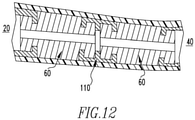
- the flexible stimulation device 10 includes two flexible connection portions 60. Multiple flexible connection portions may allow for the flexible stimulation device to flex in different directions during use.
- the additional flexible connection portions 60 may be connected by rigid intermediate portions 110, as shown in Fig. 12 .
- the flexible connection portions 60 may engage with the intermediate portions 110 as previously described above for the engagement between the flexible connection portion 60 and the base portion 20 and the distal portion 40.
- a flexible connection portion 60 may engage directly with an adjacent flexible connection portion 60.
- the multiple flexible connection portions 60 may be located between the base portion 20 and the distal portion 40.
- each flexible connection portion 60 may be located between the distal end 42 and the proximal end 44 of the distal portion 40 and at least one flexible connection portion 60 may be located between the base portion 20 and the distal portion 40.
- each flexible connection portion 60 allows for the flexible stimulation device 10 to return or reset to its original shape after the force is removed.
- each additional flexible connection portion 60 may be the same or similar to the total length Lc, a flexible length L F and a width Wc of a single flexible connection portion 60.
- each flexible connection portion 60 may be the same or similar size.
- any other suitable arrangement may be used, e.g., the total length Lc, flexible length L F and/or width Wc of a first flexible connection portion 60 may be equal to, greater than or less than the total length, flexible length and/or width of each additional flexible connection portion 60.
- each flexible connection portion 60 may be selected to allow for the desired amount of flexibility and elasticity in different areas of the flexible stimulation device 10.
- the distal portion 40, the flexible connection portion 60 and a length of the base portion 20 may be covered by a flexible outer sleeve 80.
- the flexible outer sleeve 80 extends from the shoulder 28 of the base portion 20 and completely covers the flexible connection 60 and the distal portion 40.
- the flexible outer sleeve 80 may cover at least 20 percent of the base portion 20, e.g., at least 25 percent or at least 30 percent.
- the shoulder 28 allows the flexible outer sleeve 80 to be even with the handle 27 of the base portion 20.
- the flexible outer sleeve 80 is configured for enhanced stimulation.
- the flexible outer sleeve 80 comprises an upward curved shape to provide increased "G" spot stimulation.
- any other suitable shape of flexible outer sleeve 80 may be used, e.g., straight, downward curve, complex curve or the like.
- the flexible stimulation device 10 comprises the appropriate wiring or other conductors (not shown) between the vibrating motor 52, the power supply 32, the control module 34 and the control button 36.
- the control module 34 may be a printed circuit board (PCB) configured to control the vibrating motor 52.
- the control module 34 may be pre-programmed for a variety of vibrating patterns to control the direction, frequency, and strength of the vibration of the vibrating motor 52.
- the vibrating motor 52 may be configured to vibrate with various frequencies and strengths.
- the vibrating motor 52 may be configured to produce increasing levels of intensity, consistent vibration, pulsing vibration, different wavelengths of vibration or the like.
- the control button 36 may be a "push-on/push-off' power switch used to toggle the different modes of the vibrating motor 52 of flexible stimulation device 10.
- the control button 36 may sequentially select a plurality of vibration modes and/or intensities.
- the flexible stimulation device 10 may include a "push-on/push-off' power switch and additional buttons (not shown) to select a plurality of vibration modes and/or intensities.
- a user may also control the vibrating motor 52 through any other suitable means, e.g., a remote control, proximity sensors, touch controls or the like.
- the vibrating motor 52 may be a high-power DC motor with a load current that may reach more than 1 amp. However, any other suitable type of motor that can provide the desired vibration of the distal portion 40 of the flexible stimulation device 10 may be used. In accordance with an embodiment of the present invention, the vibrating motor 52 may be sized and arranged to be retained within the internal cavity 50 of the distal portion 40.
- the power supply 32 may be a battery.
- the power supply 32 may be a rechargeable lithium battery, alkaline batteries or the like. However, any other suitable type of power supply may be used.
- the power supply 32 may be recharged by receiving electricity through the charging port 38 located in the handle 27 of the base portion 20.
- the control module 34 may be provided as a printed circuit board 100 comprising a top layer 102 and a bottom layer 104.
- the top layer 102 of the PCB 100 includes a power switch that allows for the vibrating motor to be turned on and off by the control button 36.
- top layer 102 of the PCB includes additional S and F input buttons for the selection of different vibration modes.
- the bottom layer 104 of the PCB 100 includes additional components for controlling the flexible stimulation device 10.
- Figs. 9-11 illustrate exemplary electronic circuit diagrams that may be used to control the operation of a flexible stimulation device 10 in accordance with an embodiment of the present invention.
- the electrical components are known to those skilled in the art and implement the necessary power and control features according to embodiments of the flexible stimulation device 10. In accordance with another embodiment of the present invention, any other suitable configuration of electrical components may be used.
- Fig. 9 is a circuit diagram 200 showing the electrical connections between the top layer of the PCB of the control module, the power supply and the vibrating motor in accordance with an embodiment of the present invention.
- Fig. 10 is a circuit diagram 300 for a charging circuit in accordance with an embodiment of the present invention.
- Fig. 11 is a circuit diagram 400 for a power supply in accordance with an embodiment of the present invention.
- the flexible connection portion 60 may be made from any suitable resilient elastic material, such as thermoplastic elastomer, thermoplastic rubber, silicone or the like. In accordance with an embodiment of the present invention, the flexible connection portion 60 is substantially free of metal. In accordance with an embodiment of the present invention, the flexible outer sleeve 80 may be made from soft rubber or silicone due to its ability to transmit vibration and stimulation and so that it can be easily cleaned after use.
- the flexible stimulation device 10 may have at least one proximity sensor for controlling vibratory intensities in response the proximity sensor becoming activated by being close to a user's body parts being massaged similar to the proximity sensors disclosed in U.S. Pat. No. 8,308,667 issued Nov. 13, 2012 , which is incorporated herein by reference.
- any numerical range recited herein is intended to include all sub-ranges subsumed therein.
- a range of "1 to 10" is intended to include all sub-ranges between (and including) the recited minimum value of 1 and the recited maximum value of 10, that is, having a minimum value equal to or greater than 1 and a maximum value of equal to or less than 10.
Landscapes
- Health & Medical Sciences (AREA)
- Epidemiology (AREA)
- Pain & Pain Management (AREA)
- Physical Education & Sports Medicine (AREA)
- Rehabilitation Therapy (AREA)
- Life Sciences & Earth Sciences (AREA)
- Animal Behavior & Ethology (AREA)
- General Health & Medical Sciences (AREA)
- Public Health (AREA)
- Veterinary Medicine (AREA)
- Reproductive Health (AREA)
- Percussion Or Vibration Massage (AREA)
Claims (14)
- Flexible Stimulationsvorrichtung (10), umfassend:ein erstes Geräteende (12);einen Basisabschnitt (20) mit einem ersten Basisende (22) neben dem ersten Geräteende (12) und einem zweiten Basisende (24);ein zweites Geräteende (14);einen distalen Abschnitt (40), der sich vom zweiten Vorrichtungsende (14) zum zweiten Basisende (24) erstreckt; undmindestens einen flexiblen elastischen Verbindungsabschnitt (60) zwischen dem zweiten Basisende (24) und dem distalen Abschnitt (40),- der mindestens eine flexible elastische Verbindungsabschnitt (60) ermöglicht, dass der distale Abschnitt (40) einen Bewegungswinkelbereich von 5 bis 60 Grad in jeder Richtung von einer Längsachse der flexiblen Stimulationsvorrichtung (10) umfasst; und- der mindestens eine flexible elastische Verbindungsabschnitt (60) so ausgelegt ist, dass er dem distalen Abschnitt (40) ermöglicht, elastisch in seine ursprüngliche Form zurückzukehren;dadurch gekennzeichnet, dassder mindestens eine flexible elastische Verbindungsabschnitt (60) einen ersten radialen Kanal (68) umfasst, der in einem Körper (62) des mindestens einen flexiblen elastischen Verbindungsabschnitts (60) angrenzend an ein erstes Ende (64) und ein zweites radiales eingelassen ist Kanal (70), der in den Körper (62) angrenzend an das zweite Ende (66) eingelassen ist, und wobei der erste radiale Kanal (68) strukturiert und angeordnet ist, um mit einem flexiblen Verbindungseingriffsvorsprung (31) des Basisabschnitts (20) in Eingriff zu treten und der zweite radiale Kanal (70) strukturiert und angeordnet ist, um mit einem flexiblen Verbindungseingriffsvorsprung (31) des distalen Abschnitts (40) in Eingriff zu treten.
- Flexible Stimulationsvorrichtung (10) nach Anspruch 1, wobei der mindestens eine flexible elastische Verbindungsabschnitt (60) aus einem thermoplastischen Elastomer, thermoplastischem Gummi oder Silikon besteht.
- Flexible Stimulationsvorrichtung (10) nach Anspruch 1, wobei eine Länge des Basisabschnitts (20) mindestens 150 Prozent, vorzugsweise mindestens 200 Prozent, größer ist als eine flexible Länge des mindestens einen flexiblen elastischen Verbindungsabschnitts (60).
- Flexible Stimulationsvorrichtung (10) nach Anspruch 1, wobei das Verhältnis einer Breite des mindestens einen flexiblen elastischen Verbindungsabschnitts (60) zu einer flexiblen Länge des mindestens einen flexiblen elastischen Verbindungsabschnitts (60) beträgt 3:1 bis 1:3.
- Flexible Stimulationsvorrichtung (10) nach Anspruch 1, wobei der mindestens eine flexible elastische Verbindungsabschnitt (60) die Vibrationsübertragung von dem distalen Abschnitt (40) auf den Basisabschnitt (20) wesentlich reduziert.
- Flexible Stimulationsvorrichtung (10) nach Anspruch 1, wobei der distale Abschnitt (40) von einer flexiblen äußeren Hülle (80) bedeckt ist.
- Flexible Stimulationsvorrichtung (10) nach Anspruch 1, wobei der distale Abschnitt (40), der mindestens eine flexible Verbindungsabschnitt (60) und ein Abschnitt des Basisabschnitts (20) von einer flexiblen Außenhülle (80) bedeckt sind.
- Flexible Stimulationsvorrichtung (10) nach Anspruch 1, wobei der Basisabschnitt (20) ferner einen Griffabschnitt (27) angrenzend an das erste Vorrichtungsende (12) umfasst.
- Flexible Stimulationsvorrichtung (10) nach Anspruch 1, wobei der Basisabschnitt (20) einen inneren Hohlraum (50) umfasst, der ein elektronisches Modul hält, umfassend:eine Stromversorgung (32), vorzugsweise eine wiederaufladbare Batterie;ein Steuermodul (34); undmindestens eine Steuertaste (36).
- Flexible Stimulationsvorrichtung (10) nach Anspruch 1, wobei ein Vibrationsmittel (52) in dem distalen Abschnitt (40) getragen wird.
- Flexible Stimulationsvorrichtung (10) nach Anspruch 9, wobei das elektronische Modul in elektrischer Verbindung mit einem Vibrationsmittel (52) steht, das in dem distalen Abschnitt (40) getragen wird.
- Flexible Stimulationsvorrichtung (10) nach Anspruch 9, wobei der mindestens eine Steuerknopf (36) des elektronischen Moduls verwendet wird, um das Vibrationsmittel (52) zwischen Aus, einem ersten Vibrationsmodus und einem zweiten Vibrationsmodus umzuschalten.
- Flexible Stimulationsvorrichtung (10) nach Anspruch 9 oder 10, wobei das Vibrationsmittel (52) ein Motor ist.
- Flexible Stimulationsvorrichtung (10) nach Anspruch 1, wobei das erste Basisende (22) ein starres Gehäuse und einen inneren Hohlraum (50) umfasst;
und wobei die Vorrichtung ferner umfasst:einen distalen Abschnitt (40);mindestens einen vibrationsdämpfenden flexiblen elastischen Verbindungsabschnitt (60), der in den inneren Hohlraum (50) des Basisabschnitts (20) und den inneren Hohlraum (50) des distalen Abschnitts (40) eingreift.
Applications Claiming Priority (2)
| Application Number | Priority Date | Filing Date | Title |
|---|---|---|---|
| US201762596276P | 2017-12-08 | 2017-12-08 | |
| PCT/US2018/064746 WO2019113583A1 (en) | 2017-12-08 | 2018-12-10 | Flexible stimulation device |
Publications (2)
| Publication Number | Publication Date |
|---|---|
| EP3720409A1 EP3720409A1 (de) | 2020-10-14 |
| EP3720409B1 true EP3720409B1 (de) | 2022-02-09 |
Family
ID=65041901
Family Applications (1)
| Application Number | Title | Priority Date | Filing Date |
|---|---|---|---|
| EP18836741.1A Active EP3720409B1 (de) | 2017-12-08 | 2018-12-10 | Flexible stimulationsvorrichtung |
Country Status (3)
| Country | Link |
|---|---|
| US (3) | US20190175439A1 (de) |
| EP (1) | EP3720409B1 (de) |
| WO (1) | WO2019113583A1 (de) |
Families Citing this family (19)
| Publication number | Priority date | Publication date | Assignee | Title |
|---|---|---|---|---|
| USD868281S1 (en) * | 2017-10-25 | 2019-11-26 | EIS GmbH | Adult toy |
| USD882816S1 (en) * | 2018-06-30 | 2020-04-28 | EIS GmbH | Sex toy |
| ZAA201900138S (en) * | 2018-08-03 | 2019-10-30 | Reckitt Benckiser Health Ltd | Vibrator for massage |
| ZAA201900137S (en) * | 2018-08-03 | 2019-10-30 | Reckitt Benckiser Health Ltd | Vibrator for massage |
| USD912266S1 (en) * | 2019-09-05 | 2021-03-02 | Sheng-Pi Chen | Sex toy vibrator |
| USD971426S1 (en) * | 2020-01-17 | 2022-11-29 | Dame Products, Inc. | Hand held vibrating electromechanical stimulation device |
| EP3925588B1 (de) * | 2020-06-18 | 2023-02-08 | Shenzhen S-Hande Technology Co., Ltd. | Mit elektrischen druck-, klopf- und vibrationsfunktionen integrierte massagevorrichtung |
| USD942639S1 (en) * | 2020-06-19 | 2022-02-01 | Shenzhen S-hande Technology Co., Ltd. | Massager |
| US10940078B1 (en) | 2020-08-31 | 2021-03-09 | American Latex Corp. | Vibratory massage apparatus |
| US12458564B2 (en) * | 2022-01-26 | 2025-11-04 | Shenzhen Alltokee Technology Co., Ltd | Massage device with replaceable massage subassemblies |
| USD1026242S1 (en) | 2022-05-30 | 2024-05-07 | Mystery Vibe Limited | Sexual stimulator |
| USD1047190S1 (en) | 2022-05-30 | 2024-10-15 | Mystery Vibe Limited | Sexual stimulator |
| USD1047191S1 (en) | 2022-05-30 | 2024-10-15 | Mystery Vibe Limited | Sexual stimulator |
| USD1047188S1 (en) * | 2022-05-30 | 2024-10-15 | Mystery Vibe Limited | Sexual stimulator |
| USD1047189S1 (en) | 2022-05-30 | 2024-10-15 | Mysteryvibe Limited | Sexual stimulator |
| JP1729169S (ja) * | 2022-06-17 | 2022-11-07 | マッサージ器 | |
| US20230009837A1 (en) * | 2022-09-20 | 2023-01-12 | Shenzhen Yisheng Technology Development Co., Ltd. | Pulling type movement structure, and toy and massager using same |
| US12178775B1 (en) * | 2024-02-06 | 2024-12-31 | Junpeng WU | Sexual stimulation device |
| US12514781B2 (en) * | 2024-07-29 | 2026-01-06 | Xiaobin Zhang | Massager with plurality of massage modes and massage method |
Family Cites Families (16)
| Publication number | Priority date | Publication date | Assignee | Title |
|---|---|---|---|---|
| US5690603A (en) | 1995-09-25 | 1997-11-25 | Kain; Melissa Mia | Erogenic stimulator |
| US7081087B2 (en) | 2003-02-05 | 2006-07-25 | Carmella Jannuzzi | Sexual aid device |
| US20050273024A1 (en) | 2004-06-04 | 2005-12-08 | Nanma Manufacturing Co., Ltd. | Bendable vibrator device |
| CA2491249A1 (en) * | 2004-12-17 | 2006-06-17 | Bruce Murison | Electro-mechanical sexual stimulation device |
| US7452326B2 (en) | 2006-10-13 | 2008-11-18 | British Columbia Institute Of British Columbia | User-friendly vibrostimulation device |
| US20090234182A1 (en) * | 2008-03-17 | 2009-09-17 | Buchholz Eric K | Stress Relief Systems |
| US20100174135A1 (en) | 2009-01-06 | 2010-07-08 | Youngtack Shim | Synchronized relaxing systems and methods |
| US20110034763A1 (en) * | 2009-08-05 | 2011-02-10 | Lauren Domnick | Anthropometric Massage Device |
| US8308667B2 (en) | 2010-03-12 | 2012-11-13 | Wing Pow International Corp. | Interactive massaging device |
| US8622890B1 (en) * | 2010-12-17 | 2014-01-07 | Momentum Management, LLC | Flexible multi-configuration female sexual stimulation device |
| CN102743276B (zh) | 2012-07-24 | 2014-09-24 | 爱侣健康科技有限公司 | 全方位弯曲震动按摩器 |
| US9119763B1 (en) | 2012-09-07 | 2015-09-01 | Dan Leary | Sex toy |
| CN103517697B (zh) * | 2012-12-31 | 2016-05-18 | 爱侣健康科技有限公司 | 性刺激装置 |
| US20140357944A1 (en) * | 2013-05-30 | 2014-12-04 | Boulder Applied Physics, Inc. | High torque personal massager |
| CN104758166A (zh) | 2015-04-10 | 2015-07-08 | 姚承 | 一种养生按摩器 |
| CN107260519A (zh) | 2016-04-07 | 2017-10-20 | 深圳市零距离电子有限公司 | 一种情趣辅助装置 |
-
2018
- 2018-12-07 US US16/213,580 patent/US20190175439A1/en not_active Abandoned
- 2018-12-10 WO PCT/US2018/064746 patent/WO2019113583A1/en not_active Ceased
- 2018-12-10 EP EP18836741.1A patent/EP3720409B1/de active Active
- 2018-12-10 US US16/214,932 patent/US10524977B2/en active Active
-
2019
- 2019-12-04 US US16/702,653 patent/US20200100982A1/en not_active Abandoned
Also Published As
| Publication number | Publication date |
|---|---|
| US20190175439A1 (en) | 2019-06-13 |
| US20200100982A1 (en) | 2020-04-02 |
| EP3720409A1 (de) | 2020-10-14 |
| US10524977B2 (en) | 2020-01-07 |
| WO2019113583A1 (en) | 2019-06-13 |
| US20190175440A1 (en) | 2019-06-13 |
Similar Documents
| Publication | Publication Date | Title |
|---|---|---|
| EP3720409B1 (de) | Flexible stimulationsvorrichtung | |
| US11633325B2 (en) | Sexual stimulation device | |
| EP1477149B1 (de) | Stimulationshilfe | |
| US11793711B2 (en) | Devices for sexual stimulation | |
| US8496572B2 (en) | Massage device having serial vibrators | |
| WO2014008606A1 (en) | G-spot and clitoral stimulation device | |
| EP2892494B1 (de) | Stimulationsvorrichtung | |
| US20140188017A1 (en) | Sexual stimulation devices | |
| CN102711708A (zh) | 具有柔性底层结构的按摩装置 | |
| US20230096701A1 (en) | Ergonomic rabbit vibrator | |
| CN111565808B (zh) | 具有手部保持器、外壳和手指感应的电子控制器 | |
| US10195106B2 (en) | Deformable vibratory stimulation device | |
| US12611354B2 (en) | Water-jetting sexual stimulator | |
| KR20120060035A (ko) | 컨트롤 홈을 구비한 컨트롤러 및 이를 구비한 전동 휠체어 | |
| US20080269553A1 (en) | Powered massager for internal use on the human body | |
| US20260108416A1 (en) | Stimulation device | |
| KR200292059Y1 (ko) | 휴대용 저주파 마사지기 | |
| CN113197763A (zh) | 一种按摩装置及其控制方法 | |
| HK40039257A (en) | Girth adjustable device | |
| HK1147672B (en) | Rechargeable personal massager | |
| HK1147672A1 (en) | Rechargeable personal massager |
Legal Events
| Date | Code | Title | Description |
|---|---|---|---|
| STAA | Information on the status of an ep patent application or granted ep patent |
Free format text: STATUS: UNKNOWN |
|
| STAA | Information on the status of an ep patent application or granted ep patent |
Free format text: STATUS: THE INTERNATIONAL PUBLICATION HAS BEEN MADE |
|
| PUAI | Public reference made under article 153(3) epc to a published international application that has entered the european phase |
Free format text: ORIGINAL CODE: 0009012 |
|
| STAA | Information on the status of an ep patent application or granted ep patent |
Free format text: STATUS: REQUEST FOR EXAMINATION WAS MADE |
|
| 17P | Request for examination filed |
Effective date: 20200615 |
|
| AK | Designated contracting states |
Kind code of ref document: A1 Designated state(s): AL AT BE BG CH CY CZ DE DK EE ES FI FR GB GR HR HU IE IS IT LI LT LU LV MC MK MT NL NO PL PT RO RS SE SI SK SM TR |
|
| AX | Request for extension of the european patent |
Extension state: BA ME |
|
| STAA | Information on the status of an ep patent application or granted ep patent |
Free format text: STATUS: EXAMINATION IS IN PROGRESS |
|
| DAV | Request for validation of the european patent (deleted) | ||
| DAX | Request for extension of the european patent (deleted) | ||
| 17Q | First examination report despatched |
Effective date: 20210226 |
|
| GRAP | Despatch of communication of intention to grant a patent |
Free format text: ORIGINAL CODE: EPIDOSNIGR1 |
|
| STAA | Information on the status of an ep patent application or granted ep patent |
Free format text: STATUS: GRANT OF PATENT IS INTENDED |
|
| INTG | Intention to grant announced |
Effective date: 20210811 |
|
| GRAS | Grant fee paid |
Free format text: ORIGINAL CODE: EPIDOSNIGR3 |
|
| GRAA | (expected) grant |
Free format text: ORIGINAL CODE: 0009210 |
|
| STAA | Information on the status of an ep patent application or granted ep patent |
Free format text: STATUS: THE PATENT HAS BEEN GRANTED |
|
| AK | Designated contracting states |
Kind code of ref document: B1 Designated state(s): AL AT BE BG CH CY CZ DE DK EE ES FI FR GB GR HR HU IE IS IT LI LT LU LV MC MK MT NL NO PL PT RO RS SE SI SK SM TR |
|
| REG | Reference to a national code |
Ref country code: GB Ref legal event code: FG4D |
|
| REG | Reference to a national code |
Ref country code: CH Ref legal event code: EP Ref country code: AT Ref legal event code: REF Ref document number: 1467066 Country of ref document: AT Kind code of ref document: T Effective date: 20220215 |
|
| REG | Reference to a national code |
Ref country code: IE Ref legal event code: FG4D |
|
| REG | Reference to a national code |
Ref country code: DE Ref legal event code: R096 Ref document number: 602018030723 Country of ref document: DE |
|
| REG | Reference to a national code |
Ref country code: LT Ref legal event code: MG9D |
|
| REG | Reference to a national code |
Ref country code: NL Ref legal event code: MP Effective date: 20220209 |
|
| REG | Reference to a national code |
Ref country code: AT Ref legal event code: MK05 Ref document number: 1467066 Country of ref document: AT Kind code of ref document: T Effective date: 20220209 |
|
| PG25 | Lapsed in a contracting state [announced via postgrant information from national office to epo] |
Ref country code: SE Free format text: LAPSE BECAUSE OF FAILURE TO SUBMIT A TRANSLATION OF THE DESCRIPTION OR TO PAY THE FEE WITHIN THE PRESCRIBED TIME-LIMIT Effective date: 20220209 Ref country code: RS Free format text: LAPSE BECAUSE OF FAILURE TO SUBMIT A TRANSLATION OF THE DESCRIPTION OR TO PAY THE FEE WITHIN THE PRESCRIBED TIME-LIMIT Effective date: 20220209 Ref country code: PT Free format text: LAPSE BECAUSE OF FAILURE TO SUBMIT A TRANSLATION OF THE DESCRIPTION OR TO PAY THE FEE WITHIN THE PRESCRIBED TIME-LIMIT Effective date: 20220609 Ref country code: NO Free format text: LAPSE BECAUSE OF FAILURE TO SUBMIT A TRANSLATION OF THE DESCRIPTION OR TO PAY THE FEE WITHIN THE PRESCRIBED TIME-LIMIT Effective date: 20220509 Ref country code: NL Free format text: LAPSE BECAUSE OF FAILURE TO SUBMIT A TRANSLATION OF THE DESCRIPTION OR TO PAY THE FEE WITHIN THE PRESCRIBED TIME-LIMIT Effective date: 20220209 Ref country code: LT Free format text: LAPSE BECAUSE OF FAILURE TO SUBMIT A TRANSLATION OF THE DESCRIPTION OR TO PAY THE FEE WITHIN THE PRESCRIBED TIME-LIMIT Effective date: 20220209 Ref country code: HR Free format text: LAPSE BECAUSE OF FAILURE TO SUBMIT A TRANSLATION OF THE DESCRIPTION OR TO PAY THE FEE WITHIN THE PRESCRIBED TIME-LIMIT Effective date: 20220209 Ref country code: ES Free format text: LAPSE BECAUSE OF FAILURE TO SUBMIT A TRANSLATION OF THE DESCRIPTION OR TO PAY THE FEE WITHIN THE PRESCRIBED TIME-LIMIT Effective date: 20220209 Ref country code: BG Free format text: LAPSE BECAUSE OF FAILURE TO SUBMIT A TRANSLATION OF THE DESCRIPTION OR TO PAY THE FEE WITHIN THE PRESCRIBED TIME-LIMIT Effective date: 20220509 |
|
| PG25 | Lapsed in a contracting state [announced via postgrant information from national office to epo] |
Ref country code: PL Free format text: LAPSE BECAUSE OF FAILURE TO SUBMIT A TRANSLATION OF THE DESCRIPTION OR TO PAY THE FEE WITHIN THE PRESCRIBED TIME-LIMIT Effective date: 20220209 Ref country code: LV Free format text: LAPSE BECAUSE OF FAILURE TO SUBMIT A TRANSLATION OF THE DESCRIPTION OR TO PAY THE FEE WITHIN THE PRESCRIBED TIME-LIMIT Effective date: 20220209 Ref country code: GR Free format text: LAPSE BECAUSE OF FAILURE TO SUBMIT A TRANSLATION OF THE DESCRIPTION OR TO PAY THE FEE WITHIN THE PRESCRIBED TIME-LIMIT Effective date: 20220510 Ref country code: FI Free format text: LAPSE BECAUSE OF FAILURE TO SUBMIT A TRANSLATION OF THE DESCRIPTION OR TO PAY THE FEE WITHIN THE PRESCRIBED TIME-LIMIT Effective date: 20220209 Ref country code: AT Free format text: LAPSE BECAUSE OF FAILURE TO SUBMIT A TRANSLATION OF THE DESCRIPTION OR TO PAY THE FEE WITHIN THE PRESCRIBED TIME-LIMIT Effective date: 20220209 |
|
| PG25 | Lapsed in a contracting state [announced via postgrant information from national office to epo] |
Ref country code: IS Free format text: LAPSE BECAUSE OF FAILURE TO SUBMIT A TRANSLATION OF THE DESCRIPTION OR TO PAY THE FEE WITHIN THE PRESCRIBED TIME-LIMIT Effective date: 20220609 |
|
| PG25 | Lapsed in a contracting state [announced via postgrant information from national office to epo] |
Ref country code: SM Free format text: LAPSE BECAUSE OF FAILURE TO SUBMIT A TRANSLATION OF THE DESCRIPTION OR TO PAY THE FEE WITHIN THE PRESCRIBED TIME-LIMIT Effective date: 20220209 Ref country code: SK Free format text: LAPSE BECAUSE OF FAILURE TO SUBMIT A TRANSLATION OF THE DESCRIPTION OR TO PAY THE FEE WITHIN THE PRESCRIBED TIME-LIMIT Effective date: 20220209 Ref country code: RO Free format text: LAPSE BECAUSE OF FAILURE TO SUBMIT A TRANSLATION OF THE DESCRIPTION OR TO PAY THE FEE WITHIN THE PRESCRIBED TIME-LIMIT Effective date: 20220209 Ref country code: EE Free format text: LAPSE BECAUSE OF FAILURE TO SUBMIT A TRANSLATION OF THE DESCRIPTION OR TO PAY THE FEE WITHIN THE PRESCRIBED TIME-LIMIT Effective date: 20220209 Ref country code: DK Free format text: LAPSE BECAUSE OF FAILURE TO SUBMIT A TRANSLATION OF THE DESCRIPTION OR TO PAY THE FEE WITHIN THE PRESCRIBED TIME-LIMIT Effective date: 20220209 Ref country code: CZ Free format text: LAPSE BECAUSE OF FAILURE TO SUBMIT A TRANSLATION OF THE DESCRIPTION OR TO PAY THE FEE WITHIN THE PRESCRIBED TIME-LIMIT Effective date: 20220209 |
|
| REG | Reference to a national code |
Ref country code: DE Ref legal event code: R097 Ref document number: 602018030723 Country of ref document: DE |
|
| PG25 | Lapsed in a contracting state [announced via postgrant information from national office to epo] |
Ref country code: AL Free format text: LAPSE BECAUSE OF FAILURE TO SUBMIT A TRANSLATION OF THE DESCRIPTION OR TO PAY THE FEE WITHIN THE PRESCRIBED TIME-LIMIT Effective date: 20220209 |
|
| PLBE | No opposition filed within time limit |
Free format text: ORIGINAL CODE: 0009261 |
|
| STAA | Information on the status of an ep patent application or granted ep patent |
Free format text: STATUS: NO OPPOSITION FILED WITHIN TIME LIMIT |
|
| 26N | No opposition filed |
Effective date: 20221110 |
|
| PG25 | Lapsed in a contracting state [announced via postgrant information from national office to epo] |
Ref country code: SI Free format text: LAPSE BECAUSE OF FAILURE TO SUBMIT A TRANSLATION OF THE DESCRIPTION OR TO PAY THE FEE WITHIN THE PRESCRIBED TIME-LIMIT Effective date: 20220209 |
|
| PG25 | Lapsed in a contracting state [announced via postgrant information from national office to epo] |
Ref country code: IT Free format text: LAPSE BECAUSE OF FAILURE TO SUBMIT A TRANSLATION OF THE DESCRIPTION OR TO PAY THE FEE WITHIN THE PRESCRIBED TIME-LIMIT Effective date: 20220209 |
|
| REG | Reference to a national code |
Ref country code: CH Ref legal event code: PL |
|
| REG | Reference to a national code |
Ref country code: BE Ref legal event code: MM Effective date: 20221231 |
|
| PG25 | Lapsed in a contracting state [announced via postgrant information from national office to epo] |
Ref country code: LU Free format text: LAPSE BECAUSE OF NON-PAYMENT OF DUE FEES Effective date: 20221210 |
|
| PG25 | Lapsed in a contracting state [announced via postgrant information from national office to epo] |
Ref country code: LI Free format text: LAPSE BECAUSE OF NON-PAYMENT OF DUE FEES Effective date: 20221231 Ref country code: IE Free format text: LAPSE BECAUSE OF NON-PAYMENT OF DUE FEES Effective date: 20221210 Ref country code: CH Free format text: LAPSE BECAUSE OF NON-PAYMENT OF DUE FEES Effective date: 20221231 |
|
| PG25 | Lapsed in a contracting state [announced via postgrant information from national office to epo] |
Ref country code: FR Free format text: LAPSE BECAUSE OF NON-PAYMENT OF DUE FEES Effective date: 20221231 Ref country code: BE Free format text: LAPSE BECAUSE OF NON-PAYMENT OF DUE FEES Effective date: 20221231 |
|
| PG25 | Lapsed in a contracting state [announced via postgrant information from national office to epo] |
Ref country code: CY Free format text: LAPSE BECAUSE OF FAILURE TO SUBMIT A TRANSLATION OF THE DESCRIPTION OR TO PAY THE FEE WITHIN THE PRESCRIBED TIME-LIMIT Effective date: 20220209 |
|
| PG25 | Lapsed in a contracting state [announced via postgrant information from national office to epo] |
Ref country code: MK Free format text: LAPSE BECAUSE OF FAILURE TO SUBMIT A TRANSLATION OF THE DESCRIPTION OR TO PAY THE FEE WITHIN THE PRESCRIBED TIME-LIMIT Effective date: 20220209 Ref country code: HU Free format text: LAPSE BECAUSE OF FAILURE TO SUBMIT A TRANSLATION OF THE DESCRIPTION OR TO PAY THE FEE WITHIN THE PRESCRIBED TIME-LIMIT; INVALID AB INITIO Effective date: 20181210 |
|
| PG25 | Lapsed in a contracting state [announced via postgrant information from national office to epo] |
Ref country code: MC Free format text: LAPSE BECAUSE OF FAILURE TO SUBMIT A TRANSLATION OF THE DESCRIPTION OR TO PAY THE FEE WITHIN THE PRESCRIBED TIME-LIMIT Effective date: 20220209 |
|
| PG25 | Lapsed in a contracting state [announced via postgrant information from national office to epo] |
Ref country code: TR Free format text: LAPSE BECAUSE OF FAILURE TO SUBMIT A TRANSLATION OF THE DESCRIPTION OR TO PAY THE FEE WITHIN THE PRESCRIBED TIME-LIMIT Effective date: 20220209 Ref country code: MC Free format text: LAPSE BECAUSE OF FAILURE TO SUBMIT A TRANSLATION OF THE DESCRIPTION OR TO PAY THE FEE WITHIN THE PRESCRIBED TIME-LIMIT Effective date: 20220209 |
|
| PG25 | Lapsed in a contracting state [announced via postgrant information from national office to epo] |
Ref country code: MT Free format text: LAPSE BECAUSE OF FAILURE TO SUBMIT A TRANSLATION OF THE DESCRIPTION OR TO PAY THE FEE WITHIN THE PRESCRIBED TIME-LIMIT Effective date: 20220209 |
|
| PGFP | Annual fee paid to national office [announced via postgrant information from national office to epo] |
Ref country code: DE Payment date: 20241212 Year of fee payment: 7 |
|
| PGFP | Annual fee paid to national office [announced via postgrant information from national office to epo] |
Ref country code: GB Payment date: 20241227 Year of fee payment: 7 |