EP3720532B1 - Dispositif de protection de tube endotrachéal avec système de maintien facultatif et capteur facultatif - Google Patents
Dispositif de protection de tube endotrachéal avec système de maintien facultatif et capteur facultatif Download PDFInfo
- Publication number
- EP3720532B1 EP3720532B1 EP18830576.7A EP18830576A EP3720532B1 EP 3720532 B1 EP3720532 B1 EP 3720532B1 EP 18830576 A EP18830576 A EP 18830576A EP 3720532 B1 EP3720532 B1 EP 3720532B1
- Authority
- EP
- European Patent Office
- Prior art keywords
- tube
- protective guard
- guard system
- tubular structure
- flexible portion
- Prior art date
- Legal status (The legal status is an assumption and is not a legal conclusion. Google has not performed a legal analysis and makes no representation as to the accuracy of the status listed.)
- Active
Links
Images




Classifications
-
- A—HUMAN NECESSITIES
- A61—MEDICAL OR VETERINARY SCIENCE; HYGIENE
- A61M—DEVICES FOR INTRODUCING MEDIA INTO, OR ONTO, THE BODY; DEVICES FOR TRANSDUCING BODY MEDIA OR FOR TAKING MEDIA FROM THE BODY; DEVICES FOR PRODUCING OR ENDING SLEEP OR STUPOR
- A61M16/00—Devices for influencing the respiratory system of patients by gas treatment, e.g. ventilators; Tracheal tubes
- A61M16/04—Tracheal tubes
- A61M16/0488—Mouthpieces; Means for guiding, securing or introducing the tubes
- A61M16/0497—Tube stabilizer
-
- A—HUMAN NECESSITIES
- A61—MEDICAL OR VETERINARY SCIENCE; HYGIENE
- A61M—DEVICES FOR INTRODUCING MEDIA INTO, OR ONTO, THE BODY; DEVICES FOR TRANSDUCING BODY MEDIA OR FOR TAKING MEDIA FROM THE BODY; DEVICES FOR PRODUCING OR ENDING SLEEP OR STUPOR
- A61M16/00—Devices for influencing the respiratory system of patients by gas treatment, e.g. ventilators; Tracheal tubes
- A61M16/0003—Accessories therefor, e.g. sensors, vibrators, negative pressure
-
- A—HUMAN NECESSITIES
- A61—MEDICAL OR VETERINARY SCIENCE; HYGIENE
- A61M—DEVICES FOR INTRODUCING MEDIA INTO, OR ONTO, THE BODY; DEVICES FOR TRANSDUCING BODY MEDIA OR FOR TAKING MEDIA FROM THE BODY; DEVICES FOR PRODUCING OR ENDING SLEEP OR STUPOR
- A61M16/00—Devices for influencing the respiratory system of patients by gas treatment, e.g. ventilators; Tracheal tubes
- A61M16/0051—Devices for influencing the respiratory system of patients by gas treatment, e.g. ventilators; Tracheal tubes with alarm devices
-
- A—HUMAN NECESSITIES
- A61—MEDICAL OR VETERINARY SCIENCE; HYGIENE
- A61M—DEVICES FOR INTRODUCING MEDIA INTO, OR ONTO, THE BODY; DEVICES FOR TRANSDUCING BODY MEDIA OR FOR TAKING MEDIA FROM THE BODY; DEVICES FOR PRODUCING OR ENDING SLEEP OR STUPOR
- A61M16/00—Devices for influencing the respiratory system of patients by gas treatment, e.g. ventilators; Tracheal tubes
- A61M16/04—Tracheal tubes
-
- A—HUMAN NECESSITIES
- A61—MEDICAL OR VETERINARY SCIENCE; HYGIENE
- A61M—DEVICES FOR INTRODUCING MEDIA INTO, OR ONTO, THE BODY; DEVICES FOR TRANSDUCING BODY MEDIA OR FOR TAKING MEDIA FROM THE BODY; DEVICES FOR PRODUCING OR ENDING SLEEP OR STUPOR
- A61M16/00—Devices for influencing the respiratory system of patients by gas treatment, e.g. ventilators; Tracheal tubes
- A61M16/04—Tracheal tubes
- A61M16/0463—Tracheal tubes combined with suction tubes, catheters or the like; Outside connections
-
- A—HUMAN NECESSITIES
- A61—MEDICAL OR VETERINARY SCIENCE; HYGIENE
- A61M—DEVICES FOR INTRODUCING MEDIA INTO, OR ONTO, THE BODY; DEVICES FOR TRANSDUCING BODY MEDIA OR FOR TAKING MEDIA FROM THE BODY; DEVICES FOR PRODUCING OR ENDING SLEEP OR STUPOR
- A61M16/00—Devices for influencing the respiratory system of patients by gas treatment, e.g. ventilators; Tracheal tubes
- A61M16/04—Tracheal tubes
- A61M16/0488—Mouthpieces; Means for guiding, securing or introducing the tubes
- A61M16/049—Mouthpieces
-
- A—HUMAN NECESSITIES
- A61—MEDICAL OR VETERINARY SCIENCE; HYGIENE
- A61M—DEVICES FOR INTRODUCING MEDIA INTO, OR ONTO, THE BODY; DEVICES FOR TRANSDUCING BODY MEDIA OR FOR TAKING MEDIA FROM THE BODY; DEVICES FOR PRODUCING OR ENDING SLEEP OR STUPOR
- A61M2205/00—General characteristics of the apparatus
- A61M2205/13—General characteristics of the apparatus with means for the detection of operative contact with patient, e.g. lip sensor
-
- A—HUMAN NECESSITIES
- A61—MEDICAL OR VETERINARY SCIENCE; HYGIENE
- A61M—DEVICES FOR INTRODUCING MEDIA INTO, OR ONTO, THE BODY; DEVICES FOR TRANSDUCING BODY MEDIA OR FOR TAKING MEDIA FROM THE BODY; DEVICES FOR PRODUCING OR ENDING SLEEP OR STUPOR
- A61M2205/00—General characteristics of the apparatus
- A61M2205/18—General characteristics of the apparatus with alarm
-
- A—HUMAN NECESSITIES
- A61—MEDICAL OR VETERINARY SCIENCE; HYGIENE
- A61M—DEVICES FOR INTRODUCING MEDIA INTO, OR ONTO, THE BODY; DEVICES FOR TRANSDUCING BODY MEDIA OR FOR TAKING MEDIA FROM THE BODY; DEVICES FOR PRODUCING OR ENDING SLEEP OR STUPOR
- A61M2205/00—General characteristics of the apparatus
- A61M2205/27—General characteristics of the apparatus preventing use
- A61M2205/276—General characteristics of the apparatus preventing use preventing unwanted use
-
- A—HUMAN NECESSITIES
- A61—MEDICAL OR VETERINARY SCIENCE; HYGIENE
- A61M—DEVICES FOR INTRODUCING MEDIA INTO, OR ONTO, THE BODY; DEVICES FOR TRANSDUCING BODY MEDIA OR FOR TAKING MEDIA FROM THE BODY; DEVICES FOR PRODUCING OR ENDING SLEEP OR STUPOR
- A61M2205/00—General characteristics of the apparatus
- A61M2205/33—Controlling, regulating or measuring
- A61M2205/332—Force measuring means
Definitions
- the present invention generally relates to the field of medical protective systems and protective restraints.
- the present invention is directed to endotracheal tube guards and related holding systems and sensors.
- ETT endotracheal tube
- self-extubations retractal of the ETT
- patients intubated with an ETT are typically restrained by the wrists and sedated in order to prevent self-extubation, and are thus rendered unable to engage in key elements of reducing morbidity and mortality such as early mobilization in the form of autonomous in-bed activity, and sedation minimization to reduce hallucinations and cognitive decline, both of which have been shown to improve quality of life after intubation, and prevent PICS (post-intensive care syndrome), a form of PTSD (post-traumatic stress disorder).
- PICS post-intensive care syndrome
- PTSD post-traumatic stress disorder
- ETT holder 15 may include a mouthpiece or lip protector 16 and tube clamp 18 such as locking clamp 20 to secure the ETT through and in ETT holder 15.
- Other components of an ETT system may include attachment/inflation port 24 communicating with balloon cuff 14 via cuff tubing 44, multi-port connector 26 attachable through adjustable fitment 22, vent tube port 28 and expandable vent tube 30, bronchoscopy port 32 and lock 34, suction port 36 and suction catheter 38.
- the ETT holder may be secured in the patient's mouth using a head strap 40. Cheek protectors 42 prevent excessive rubbing on the patient's cheek.
- US2016279367 discloses an airway stabilization system including an airway device and a securing mechanism or faceplate therefor is provided which includes active stabilizing components on both the airway device and the faceplate which prevent clinically significant movement of the airway device with respect to the patient's vocal cords in response to the application of significant forces in any direction to the device, be they longitudinal, torsional/rotational or bending.
- US2007113855 discloses a respiratory apparatus includes a seal disposed within a port around a suction catheter so as to provide a sliding frictional sealing fit with the suction catheter.
- US2014018615 discloses an extendable intubation device is disclosed that includes a tube assembly having a plurality of elongated tubes.
- Embodiments help to hinder self-extubation of the ETT of an awake patient who may reflexively attempt removal, but also allow early mobilization and exercise necessary for preservation of as much muscle strength as possible, promotion of diaphragmatic motion necessary for liberation from the ventilator and reduction of patient stress from not being tied to the bed, allowing for sedation minimization and improved cognition.
- Embodiments may include an ETT guard to be utilized without the ETT holder, or attached to any ETT holder currently on the market.
- Embodiments may also include a sensor that alarms when the ETT guard tube is pulled.
- Disclosed embodiments may be made from conventional and readily available, medically-approved materials such as sensors, cottons, and plastics, which are transparent, latex free, MRI and other diagnostic modality-friendly, potentially disposable, lightweight, quickly and easily attachable and detachable, sturdy, and cleanable.
- the ETT guard tube encases the ETT, but does not touch it.
- the proximal end of the ETT guard tube is at the distal end of the lip protector of the ETT holder and the distal end is at the proximal portion of the multiport locking mechanism of the ventilator connector system.
- the ETT guard tube may have a telescoping mechanism or other longitudinal expansion mechanism within the body of the tube for length adjustability.
- the proximal straps are rigid and attach within the head straps of the ETT holder system.
- the distal straps are flexible and also attach to the head straps of the ETT holder system.
- the portion of the ETT guard tube distal to the rigid straps and proximal to the flexible straps is resiliently expandable or stretchable in a longitudinal direction when pulled distally and returning to its collapsed form when released.
- a sensor may be placed on the ETT guard tube to indicate an alarm when the tube is squeezed, extended or otherwise moved.
- the ETT guard tube has a greater diameter than that of the ventilator connector system and may have different diameters from proximal to distal ends.
- the ETT guard tube may be reconfigured to accommodate various commercially available multi-port connector systems.
- Embodiments of the systems disclosed may include an ETT holder system to include a tube clamp with locking mechanism, mouth piece, lip protector, cheek protectors and padded head straps with hook and loop fasteners, in continuity.
- the ETT holder system may also include an annular connector on the mouth piece portion for direct and secure connection to the ETT guard tube, which may eliminate the need for the rigid and flexible straps between the ETT holder and ETT guard tube.
- a medical staff person places the ETT guard tube around the ETT system after intubation at the lengthwise opening assuring that the ventilator port of the distal ETT system protrudes from that opening.
- the length of the ETT guard tube is adjusted using the telescoping mechanism.
- the ETT guard tube is locked in place using the securement mechanisms.
- the embodiment of the disclosed system allows distal pulling on the ETT guard tube without dislodgement of the ETT system which prevents the awake and so-inclined subject from dislodging the ETT system.
- Other advantages of the disclosed system include providing a safe level of freedom and exercise while preventing self-extubation by a confused or inattentive patient.
- Embodiments enclosed herein offer an ETT guard with or without an ETT holder as part of a complete system, thereby allowing touching and pulling on the ETT guard without moving the ETT encased within it and may include a sensor that alarms when the device is pulled upon.
- a sensor that alarms when the device is pulled upon.
- an embodiment of an ETT guard as disclosed herein may include guard tube 50 formed as an elongate tube structure configured and dimensioned to fit over the ETT without contacting it.
- a flexible portion 52 is provided at the proximal end of tube 50.
- the proximal end of tube 50 above flexible portion 52 is configured for attachment to an ETT holder system, such as tube holder mouthpiece 16.
- the attachment configuration of the proximal end may comprise a specially configured connector or collar, or the tube may simply terminate with a smooth edge adapted to contact mouthpiece 16.
- Movement sensor 58 may be positioned also in the region of flexible portion 52 in order to detect motion of tube 50 resulting from patient touches or attempts at removal as described further below.
- Flexible portion 52 allows tube 50 to be moved slightly sideto-side, or pulled distally, without imparting any motion to the ETT itself. This can be critical for avoiding dislodgment of the ETT, which can happen from even very small movements depending on the patient and clinical situation. Movements of inch and potentially less can be sufficient to dislodge the ETT, leading to potentially life threatening complications. Allowing the patient to cause a small amount of motion on the tube guard also may tend to decrease the likelihood of a patient pulling or otherwise handling the tube to the point of causing problematic movement of the ETT by providing a sensation of movement of the device without actually allowing the ETT itself to move.
- the proximal end of tube 50 may include attachment means for securing it to a conventional ETT tube holder mouthpiece 16.
- attachment means may comprise appropriate attachment openings or connection points (such as rigid connection point 62a and flexible connection point 62b) in tube 50 such that rigid strap 60a and flexible strap 60b may be used to secure the tube to the holder.
- rigid strap 60a may be secured at the proximal end of tube 50 and flexible strap 60b secured somewhat more distally, below flexible portion 52.
- openings along the proximal end of tube 50 may be used to secure the tube to the holder via zip ties or other commonly used attachment devices.
- guard tube 50 may be utilized with a wide variety of different holder systems without the need for a specifically adapted system such as explained in more detail below.
- Elongated openings 54 on sides of tube 50 allow for ports and attachments such as port 28 or bronchoscopy port 32 (depending on location) to extend through tube guard 50.
- the elongated shape of openings 54 allows for motion of tube 50 when flexible portion 52 is extended due to patient contact with the tube.
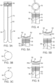
- At least one parting line 70 is provided, extending along the longitudinal extent of the guard tube as shown, for example, in FIG. 3A .
- a single parting line 70 is provided on one side of tube 50 and longitudinal hinge 74 provided opposite, as shown in FIG. 3B .
- a single connector 72 runs along parting line 70 and tube 50 opens along hinge 74.
- Detent connector 72 may comprise interfering/interlocking longitudinal ridges that lock together under sufficient finger pressure and then may be removed by appropriate finger pressure adjacent the joined edges to snap the edges apart, something easily accomplished by healthcare personnel, but not by a typical, intubate patient.
- two parting lines 70 may be provided, one on each side of the tube.
- they may both be fitted with connectors such as interlocking ridges 72, which then allow the two parted halves of tube 50 to be pushed and locked together and then parted by separating the connectors with appropriate finger pressure.
- both connection 72 and hinge 74 may alternately be provided as one or more shorter connectors and hinges, respectively.
- Opening 56 permits a second, smaller patient access tube such as a nasogastric tube to be placed within guard tube 50.
- a second, smaller patient access tube such as a nasogastric tube
- the guard tube may be placed or removed without removing or detaching the nasogastric tube.
- the nasogastric tube may be later added to guard tube 50 without disturbing the ETT therein.
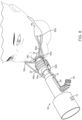
- attachment collar 76 is provided at the proximal end of tube 50, proximally with respect to flexible portion 52. Attachment collar 76 may have a notch and groove to form keyway 78.
- a protrusion sized to be received within the opening of attachment collar 76 is provided with extending key 82. To connect the two parts, tube 50 and attachment collar 76 are placed over the mouthpiece and rotated to lock it in place via key 82 and keyway 78.
- attachment collar 76a ( FIG. 6 ) is provided with an annular groove on the inside surface. This annular groove is sized to receive annular protrusion 84 on alternative mouthpiece 80a when tube 50 is opened and closed along parting line(s) 70.
- Sensor 58 may take a variety of forms. It may be a motion sensor that simply detects motion of tube 50 when exceeding predetermined threshold levels or it may be a strain gauge-type sensor that detects changes in length of flexible portion 52, also with set threshold, if desired. Sensor 58 may be connected with the patient's monitoring system and send an alarm to attending personnel when thresholds of movement or elongation are exceeded. This provides an immediate alert of any movement, which may thus prevent unintended dislodgement of the ETT.
- tube 50 forms an elongate tube structure made in two telescoping parts 50a and 50b. Both tube parts include hinges 74 and closure elements 72.
- Proximal tube part 50b is adapted to connect with a distal collar 76a using an annular ring connector such as annular protrusion 84 in FIG. 6 .
- Flexible portion 52 is proximally connected to distal collar 76a and proximal collar 76b connects flexible portion 52 to tube holder mouthpiece 16.
- flexible straps 60a are connected to distal collar 76a and rigid straps 60b are connected to proximal collar 76b.
- Distal part 50a of telescoping tube 50 has a large distal end to accommodate connector ports and a smaller proximal end with ridges compatible with ridges on inner, proximal tube part 50b in order to provide an adjustable length to accommodate different length ETTs and other intubation devices.
- Inner, proximal tube part 50b has corresponding ridges to interface with the ridges on tube part 50a.
- Elongate side ports 54 are provide through both tube parts.
- a protective guard system for orally or nasally placed patient access tubes comprises an elongate tubular structure configured and dimensioned to surround an orally or nasally placed patient access tube with a distal end configured to engage a mouthpiece of a tube holder securing the placed tube in the patient's mouth.
- the elongate tubular structure has a flexible portion and a substantially rigid portion.
- the substantially rigid portion defines at least one longitudinally extending opening configured and dimensioned to receive a port or connector.
- the elongate tubular structure is further configured to be opened for lateral placement around or removal from the placed access tube without dislodging the placed access tube from its position in the patient or disconnecting the placed tube from connected devices.
- the disclosed system provides unique features that prevent self-extubation while not strapped to a bed or chair for an awake and at-risk patient who might otherwise intentionally or unintentionally self-extubate, and encourage early mobilization and exercise promoting the strength required for advancement from the ventilator.
- the increased freedom provided by the disclosed system allows for reduced patient agitation and therefore sedation medication may be decreased and minimized which in turn promotes increased patient cognition and thereby would be more likely to reduce the incidence of delirium and PICS.
Landscapes
- Health & Medical Sciences (AREA)
- Pulmonology (AREA)
- Heart & Thoracic Surgery (AREA)
- Engineering & Computer Science (AREA)
- Anesthesiology (AREA)
- Biomedical Technology (AREA)
- Emergency Medicine (AREA)
- Hematology (AREA)
- Life Sciences & Earth Sciences (AREA)
- Animal Behavior & Ethology (AREA)
- General Health & Medical Sciences (AREA)
- Public Health (AREA)
- Veterinary Medicine (AREA)
- Otolaryngology (AREA)
- Infusion, Injection, And Reservoir Apparatuses (AREA)
Claims (14)
- Dispositif de protection de tubes d'accès patient placés par voie orale ou nasale, comprenant :une structure tubulaire allongée (50) configurée et dimensionnée pour entourer un tube d'accès patient placé par voie orale ou nasale avec un espace entre le tube placé et la structure tubulaire environnante (50), ladite structure tubulaire ayant une longueur au moins sensiblement égale à la longueur du tube placé s'étendant depuis la bouche du patient et une extrémité distale configurée pour engager un embout buccal d'un support de tube fixant le tube placé dans la bouche du patient, dans lequel :ladite structure tubulaire allongée (50) a une partie flexible (52) et une partie sensiblement rigide ;ladite partie sensiblement rigide définit au moins une ouverture s'étendant longitudinalement (54) configurée et dimensionnée pour recevoir un orifice ou un connecteur du tube placé à travers et dimensionnée pour permettre le mouvement de la partie sensiblement rigide sans interférer avec le fonctionnement de l'orifice ou du connecteur ; etladite structure tubulaire allongée est en outre configurée pour être ouverte pour un placement latéral autour ou un retrait du tube d'accès placé sans déloger le tube d'accès placé de sa position dans le patient ou déconnecter le tube placé des dispositifs connectés ;dans lequel ladite partie flexible est configurée et dimensionnée pour fournir au moins une dilatation et une contraction dans une direction longitudinale, avec une extrémité distale configurée pour s'accoupler avec l'embouchure d'un support de tube et une extrémité proximale s'accouplant avec la partie sensiblement rigide.
- Dispositif de protection selon la revendication 1, comprenant en outre un capteur de mouvement (58) monté avec la structure tubulaire allongée (50), ledit capteur de mouvement configuré pour détecter un mouvement du système dépassant un seuil de mouvement prédéterminé.
- Dispositif de protection selon la revendication 2, dans lequel ledit capteur de mouvement (50) comprend un capteur configuré pour détecter l'allongement de la portion flexible (52) .
- Dispositif de protection selon l'une quelconque des revendications 1 à 3, dans lequel ladite structure tubulaire allongée (50) a une ligne de séparation s'étendant longitudinalement (70) munie de moyens de verrouillage (72) et une structure de charnière s'étendant opposée (74) de sorte que ladite la structure tubulaire allongée (50) peut être ouverte pour être retirée et remplacée du tube d'accès placé.
- Dispositif de protection selon l'une quelconque des revendications 1 à 3, dans lequel ladite structure tubulaire allongée a au moins deux lignes de séparation opposées s'étendant longitudinalement (70), chacune desdites lignes de séparation étant pourvue de moyens de verrouillage (72) de sorte que ladite structure tubulaire allongée (50) peut se séparer en au moins deux parties à retirer et à remplacer du tube d'accès placé.
- Dispositif de protection selon l'une quelconque des revendications 1 à 5, dans lequel ladite partie sensiblement rigide comprend une structure télescopique (50a, 50b) pour un réglage longitudinal de la longueur.
- Dispositif de protection selon l'une quelconque des revendications 1 à 6, dans lequel ladite structure tubulaire allongée (50) comprend en outre un collier de fixation proximal (76b) disposé entre ladite partie sensiblement rigide et ladite partie flexible, et un collier de fixation distal (76a) au niveau de l'extrémité distale de la partie flexible (52) dans lequel ledit collier de fixation distal est configuré pour engager l'embouchure du support de tube.
- Dispositif de protection selon la revendication 7, dans lequel ladite partie flexible (52) et ladite partie sensiblement rigide sont formées séparément et amovibles et attachables au niveau dudit collier de fixation proximal (76b) .
- Dispositif de protection selon l'une quelconque des revendications 1 à 8, comprenant en outre :des points de connexion rigides (62a) positionnés sur des côtés sensiblement opposés et distalement ou sur un aspect distal de la partie flexible (52) ;des sangles de connexion longitudinalement inextensibles (60a) pouvant être fixées entre chaque dit point de connexion rigide (62a) et adaptées pour être fixées à une sangle de tête du porte-tube ;des points de connexion flexibles (62b) positionnés sur des côtés sensiblement opposés et à proximité de ou sur un aspect proximal de la partie flexible (52) ; etdes sangles de connexion longitudinalement extensibles (60b) pouvant être fixées entre chaque dit point de connexion proximal (62a, 62b) et adaptées pour être fixées à une sangle de tête du porte-tube.
- Dispositif de protection selon une quelconque revendication précédente, comprenant en outre :un porte-tube (15) comprenant un embout porte-tube (16) ; etun connecteur (76, 76a, 76b, 80, 84) adapté pour s'accoupler avec l'embout porte-tube (16) disposé à l'extrémité distale de la partie flexible (52).
- Dispositif de protection selon la revendication 10, dans lequel ledit connecteur (84) comprend un collier de fixation (76) disposé autour de l'extrémité distale de la partie flexible (52) et une partie de fixation correspondante sur l'embout buccal du support de tube (80, 84).
- Dispositif de protection selon la revendication 11, dans lequel l'un dudit collier de fixation de partie flexible (76) et de ladite partie de fixation d'accouplement comprend une clavette (80) et l'un d'une rainure de clavette d'accouplement (78) de sorte que la structure tubulaire allongée (52) peut être accouplée à l'embout porte-tube (16) et tournée pour verrouiller ladite structure audit embout.
- Dispositif de protection selon la revendication 11, dans lequel ledit collier de fixation de partie flexible (76) et ladite partie de fixation d'accouplement comprennent ensemble une bague annulaire d'accouplement (84) et un évidement annulaire de sorte que la structure de tube allongé (52) peut être accouplée avec l'embout porte tube (16) en ouvrant la structure tubulaire allongée (52) pour engager ladite bague annulaire et ledit évidement annulaire.
- Dispositif de protection selon une quelconque revendication précédente, dans lequel ladite partie flexible (52) de la structure tubulaire allongée (50) définit une ouverture (56) disposée pour être ouverte avec la structure tubulaire allongée et configurée pour recevoir un tube d'accès nasal à travers celle-ci.
Applications Claiming Priority (2)
| Application Number | Priority Date | Filing Date | Title |
|---|---|---|---|
| US201762595778P | 2017-12-07 | 2017-12-07 | |
| PCT/US2018/064603 WO2019113536A1 (fr) | 2017-12-07 | 2018-12-07 | Dispositif de protection de tube endotrachéal avec système de maintien facultatif et capteur facultatif |
Publications (3)
| Publication Number | Publication Date |
|---|---|
| EP3720532A1 EP3720532A1 (fr) | 2020-10-14 |
| EP3720532C0 EP3720532C0 (fr) | 2023-08-30 |
| EP3720532B1 true EP3720532B1 (fr) | 2023-08-30 |
Family
ID=65003478
Family Applications (1)
| Application Number | Title | Priority Date | Filing Date |
|---|---|---|---|
| EP18830576.7A Active EP3720532B1 (fr) | 2017-12-07 | 2018-12-07 | Dispositif de protection de tube endotrachéal avec système de maintien facultatif et capteur facultatif |
Country Status (8)
| Country | Link |
|---|---|
| US (3) | US11660412B2 (fr) |
| EP (1) | EP3720532B1 (fr) |
| JP (1) | JP7221547B2 (fr) |
| CN (1) | CN111432867B (fr) |
| AU (1) | AU2018379071B2 (fr) |
| BR (1) | BR112020012128B1 (fr) |
| CA (1) | CA3084265A1 (fr) |
| WO (1) | WO2019113536A1 (fr) |
Families Citing this family (1)
| Publication number | Priority date | Publication date | Assignee | Title |
|---|---|---|---|---|
| US11745203B2 (en) | 2020-03-26 | 2023-09-05 | Tyler Cavaness | Spray gun and hose cover |
Family Cites Families (11)
| Publication number | Priority date | Publication date | Assignee | Title |
|---|---|---|---|---|
| US4637384A (en) * | 1985-02-15 | 1987-01-20 | The Boc Group, Inc. | Coaxial breathing circuit |
| US5647358A (en) * | 1996-03-20 | 1997-07-15 | Vilasi; Joseph | Expandable inter vivos tube |
| US20070113855A1 (en) * | 2005-11-18 | 2007-05-24 | Kimberly-Clark Worldwide, Inc. | Respiratory apparatus with improved seal |
| US9468730B2 (en) * | 2006-02-06 | 2016-10-18 | Lazarus Medical, LLC | Ventilator to tracheotomy tube coupling |
| US7866313B2 (en) | 2007-01-02 | 2011-01-11 | Isen Innovations, Llc | Oral airways that facilitate tracheal intubation |
| US20100180900A1 (en) * | 2007-06-26 | 2010-07-22 | Venetec International, Inc. | Securement system for an endotracheal tube |
| US9808601B2 (en) * | 2009-10-29 | 2017-11-07 | Robert E. HELM, JR. | Sealed sterile catheter dressings |
| US9801534B2 (en) * | 2012-07-13 | 2017-10-31 | Jonathan Y. Lee | Telescopic intubation tube with distal camera |
| AU2014232693B2 (en) * | 2013-03-15 | 2016-09-08 | Applied Medical Technology, Inc. | Endotracheal tube retention system |
| JP6399597B2 (ja) * | 2014-12-16 | 2018-10-03 | アトムメディカル株式会社 | 呼吸用ガスの加温加湿器 |
| US10463822B2 (en) * | 2015-03-24 | 2019-11-05 | Securisyn Medical, Llc | Airway stabilization system |
-
2018
- 2018-12-07 EP EP18830576.7A patent/EP3720532B1/fr active Active
- 2018-12-07 US US16/956,870 patent/US11660412B2/en active Active
- 2018-12-07 CA CA3084265A patent/CA3084265A1/fr active Pending
- 2018-12-07 JP JP2020529437A patent/JP7221547B2/ja active Active
- 2018-12-07 BR BR112020012128-2A patent/BR112020012128B1/pt active IP Right Grant
- 2018-12-07 AU AU2018379071A patent/AU2018379071B2/en active Active
- 2018-12-07 WO PCT/US2018/064603 patent/WO2019113536A1/fr not_active Ceased
- 2018-12-07 CN CN201880078401.5A patent/CN111432867B/zh active Active
-
2023
- 2023-05-10 US US18/195,457 patent/US12214132B2/en active Active
-
2025
- 2025-02-03 US US19/043,820 patent/US20250177672A1/en active Pending
Also Published As
| Publication number | Publication date |
|---|---|
| JP2021505230A (ja) | 2021-02-18 |
| WO2019113536A1 (fr) | 2019-06-13 |
| US12214132B2 (en) | 2025-02-04 |
| US11660412B2 (en) | 2023-05-30 |
| AU2018379071B2 (en) | 2024-10-24 |
| US20250177672A1 (en) | 2025-06-05 |
| US20230277791A1 (en) | 2023-09-07 |
| EP3720532C0 (fr) | 2023-08-30 |
| EP3720532A1 (fr) | 2020-10-14 |
| CN111432867A (zh) | 2020-07-17 |
| BR112020012128B1 (pt) | 2024-01-30 |
| JP7221547B2 (ja) | 2023-02-14 |
| AU2018379071A1 (en) | 2020-06-04 |
| CN111432867B (zh) | 2024-03-15 |
| CA3084265A1 (fr) | 2019-06-13 |
| BR112020012128A2 (pt) | 2020-11-24 |
| US20210052841A1 (en) | 2021-02-25 |
Similar Documents
| Publication | Publication Date | Title |
|---|---|---|
| US6533761B2 (en) | Catheter securing device and bite block | |
| EP2861289B1 (fr) | Dispositif de tube nasal | |
| US20230049034A1 (en) | Airway stabilization system | |
| AU2023100076A4 (en) | Breath Sampling Interface | |
| US20250177672A1 (en) | Endotracheal tube guard with optional holding system and optional sensor | |
| US9814853B2 (en) | Airway stabilization system | |
| US20080097333A1 (en) | Bedside entanglement prevention and tubing apparatus | |
| US5520174A (en) | Tracheostomy tube guard | |
| HK40033791B (zh) | 气管内管防护装置 | |
| HK40033791A (en) | Endotracheal tube guard | |
| TWI802069B (zh) | 氣體取樣介面及氣體取樣頭 | |
| CN210096039U (zh) | 一种连袖可拆卸式约束手套 | |
| AU728099B2 (en) | Mouthpiece for endotracheal tube | |
| TWM558081U (zh) | 用於頸部之罩覆管頭的透析導管防抓裝置 | |
| BR112020011335A2 (pt) | sistema e aparelho de contenção de mão para proteção e exercício | |
| HK40034208A (en) | Protective and exercise hand restraint system and apparatus |
Legal Events
| Date | Code | Title | Description |
|---|---|---|---|
| STAA | Information on the status of an ep patent application or granted ep patent |
Free format text: STATUS: UNKNOWN |
|
| STAA | Information on the status of an ep patent application or granted ep patent |
Free format text: STATUS: THE INTERNATIONAL PUBLICATION HAS BEEN MADE |
|
| PUAI | Public reference made under article 153(3) epc to a published international application that has entered the european phase |
Free format text: ORIGINAL CODE: 0009012 |
|
| STAA | Information on the status of an ep patent application or granted ep patent |
Free format text: STATUS: REQUEST FOR EXAMINATION WAS MADE |
|
| 17P | Request for examination filed |
Effective date: 20200515 |
|
| AK | Designated contracting states |
Kind code of ref document: A1 Designated state(s): AL AT BE BG CH CY CZ DE DK EE ES FI FR GB GR HR HU IE IS IT LI LT LU LV MC MK MT NL NO PL PT RO RS SE SI SK SM TR |
|
| AX | Request for extension of the european patent |
Extension state: BA ME |
|
| DAV | Request for validation of the european patent (deleted) | ||
| DAX | Request for extension of the european patent (deleted) | ||
| REG | Reference to a national code |
Ref country code: DE Ref legal event code: R079 Ref country code: DE Ref legal event code: R079 Ref document number: 602018056595 Country of ref document: DE Free format text: PREVIOUS MAIN CLASS: A61M0016040000 Ipc: A61M0016000000 |
|
| GRAP | Despatch of communication of intention to grant a patent |
Free format text: ORIGINAL CODE: EPIDOSNIGR1 |
|
| STAA | Information on the status of an ep patent application or granted ep patent |
Free format text: STATUS: GRANT OF PATENT IS INTENDED |
|
| RIC1 | Information provided on ipc code assigned before grant |
Ipc: A61M 16/04 20060101ALI20230315BHEP Ipc: A61M 16/00 20060101AFI20230315BHEP |
|
| INTG | Intention to grant announced |
Effective date: 20230404 |
|
| GRAS | Grant fee paid |
Free format text: ORIGINAL CODE: EPIDOSNIGR3 |
|
| GRAA | (expected) grant |
Free format text: ORIGINAL CODE: 0009210 |
|
| STAA | Information on the status of an ep patent application or granted ep patent |
Free format text: STATUS: THE PATENT HAS BEEN GRANTED |
|
| AK | Designated contracting states |
Kind code of ref document: B1 Designated state(s): AL AT BE BG CH CY CZ DE DK EE ES FI FR GB GR HR HU IE IS IT LI LT LU LV MC MK MT NL NO PL PT RO RS SE SI SK SM TR |
|
| REG | Reference to a national code |
Ref country code: GB Ref legal event code: FG4D |
|
| REG | Reference to a national code |
Ref country code: CH Ref legal event code: EP |
|
| REG | Reference to a national code |
Ref country code: DE Ref legal event code: R096 Ref document number: 602018056595 Country of ref document: DE |
|
| REG | Reference to a national code |
Ref country code: IE Ref legal event code: FG4D |
|
| U01 | Request for unitary effect filed |
Effective date: 20230912 |
|
| U07 | Unitary effect registered |
Designated state(s): AT BE BG DE DK EE FI FR IT LT LU LV MT NL PT SE SI Effective date: 20230919 |
|
| PG25 | Lapsed in a contracting state [announced via postgrant information from national office to epo] |
Ref country code: GR Free format text: LAPSE BECAUSE OF FAILURE TO SUBMIT A TRANSLATION OF THE DESCRIPTION OR TO PAY THE FEE WITHIN THE PRESCRIBED TIME-LIMIT Effective date: 20231201 |
|
| PG25 | Lapsed in a contracting state [announced via postgrant information from national office to epo] |
Ref country code: IS Free format text: LAPSE BECAUSE OF FAILURE TO SUBMIT A TRANSLATION OF THE DESCRIPTION OR TO PAY THE FEE WITHIN THE PRESCRIBED TIME-LIMIT Effective date: 20231230 |
|
| PG25 | Lapsed in a contracting state [announced via postgrant information from national office to epo] |
Ref country code: RS Free format text: LAPSE BECAUSE OF FAILURE TO SUBMIT A TRANSLATION OF THE DESCRIPTION OR TO PAY THE FEE WITHIN THE PRESCRIBED TIME-LIMIT Effective date: 20230830 Ref country code: NO Free format text: LAPSE BECAUSE OF FAILURE TO SUBMIT A TRANSLATION OF THE DESCRIPTION OR TO PAY THE FEE WITHIN THE PRESCRIBED TIME-LIMIT Effective date: 20231130 Ref country code: IS Free format text: LAPSE BECAUSE OF FAILURE TO SUBMIT A TRANSLATION OF THE DESCRIPTION OR TO PAY THE FEE WITHIN THE PRESCRIBED TIME-LIMIT Effective date: 20231230 Ref country code: HR Free format text: LAPSE BECAUSE OF FAILURE TO SUBMIT A TRANSLATION OF THE DESCRIPTION OR TO PAY THE FEE WITHIN THE PRESCRIBED TIME-LIMIT Effective date: 20230830 Ref country code: GR Free format text: LAPSE BECAUSE OF FAILURE TO SUBMIT A TRANSLATION OF THE DESCRIPTION OR TO PAY THE FEE WITHIN THE PRESCRIBED TIME-LIMIT Effective date: 20231201 |
|
| U20 | Renewal fee for the european patent with unitary effect paid |
Year of fee payment: 6 Effective date: 20231227 |
|
| PG25 | Lapsed in a contracting state [announced via postgrant information from national office to epo] |
Ref country code: PL Free format text: LAPSE BECAUSE OF FAILURE TO SUBMIT A TRANSLATION OF THE DESCRIPTION OR TO PAY THE FEE WITHIN THE PRESCRIBED TIME-LIMIT Effective date: 20230830 |
|
| PG25 | Lapsed in a contracting state [announced via postgrant information from national office to epo] |
Ref country code: ES Free format text: LAPSE BECAUSE OF FAILURE TO SUBMIT A TRANSLATION OF THE DESCRIPTION OR TO PAY THE FEE WITHIN THE PRESCRIBED TIME-LIMIT Effective date: 20230830 |
|
| PG25 | Lapsed in a contracting state [announced via postgrant information from national office to epo] |
Ref country code: SM Free format text: LAPSE BECAUSE OF FAILURE TO SUBMIT A TRANSLATION OF THE DESCRIPTION OR TO PAY THE FEE WITHIN THE PRESCRIBED TIME-LIMIT Effective date: 20230830 Ref country code: RO Free format text: LAPSE BECAUSE OF FAILURE TO SUBMIT A TRANSLATION OF THE DESCRIPTION OR TO PAY THE FEE WITHIN THE PRESCRIBED TIME-LIMIT Effective date: 20230830 Ref country code: ES Free format text: LAPSE BECAUSE OF FAILURE TO SUBMIT A TRANSLATION OF THE DESCRIPTION OR TO PAY THE FEE WITHIN THE PRESCRIBED TIME-LIMIT Effective date: 20230830 Ref country code: CZ Free format text: LAPSE BECAUSE OF FAILURE TO SUBMIT A TRANSLATION OF THE DESCRIPTION OR TO PAY THE FEE WITHIN THE PRESCRIBED TIME-LIMIT Effective date: 20230830 Ref country code: SK Free format text: LAPSE BECAUSE OF FAILURE TO SUBMIT A TRANSLATION OF THE DESCRIPTION OR TO PAY THE FEE WITHIN THE PRESCRIBED TIME-LIMIT Effective date: 20230830 |
|
| REG | Reference to a national code |
Ref country code: DE Ref legal event code: R097 Ref document number: 602018056595 Country of ref document: DE |
|
| PLBE | No opposition filed within time limit |
Free format text: ORIGINAL CODE: 0009261 |
|
| STAA | Information on the status of an ep patent application or granted ep patent |
Free format text: STATUS: NO OPPOSITION FILED WITHIN TIME LIMIT |
|
| REG | Reference to a national code |
Ref country code: CH Ref legal event code: PL |
|
| 26N | No opposition filed |
Effective date: 20240603 |
|
| PG25 | Lapsed in a contracting state [announced via postgrant information from national office to epo] |
Ref country code: MC Free format text: LAPSE BECAUSE OF FAILURE TO SUBMIT A TRANSLATION OF THE DESCRIPTION OR TO PAY THE FEE WITHIN THE PRESCRIBED TIME-LIMIT Effective date: 20230830 |
|
| PG25 | Lapsed in a contracting state [announced via postgrant information from national office to epo] |
Ref country code: MC Free format text: LAPSE BECAUSE OF FAILURE TO SUBMIT A TRANSLATION OF THE DESCRIPTION OR TO PAY THE FEE WITHIN THE PRESCRIBED TIME-LIMIT Effective date: 20230830 |
|
| REG | Reference to a national code |
Ref country code: IE Ref legal event code: MM4A |
|
| PG25 | Lapsed in a contracting state [announced via postgrant information from national office to epo] |
Ref country code: IE Free format text: LAPSE BECAUSE OF NON-PAYMENT OF DUE FEES Effective date: 20231207 |
|
| PG25 | Lapsed in a contracting state [announced via postgrant information from national office to epo] |
Ref country code: CH Free format text: LAPSE BECAUSE OF NON-PAYMENT OF DUE FEES Effective date: 20231231 |
|
| PG25 | Lapsed in a contracting state [announced via postgrant information from national office to epo] |
Ref country code: IE Free format text: LAPSE BECAUSE OF NON-PAYMENT OF DUE FEES Effective date: 20231207 Ref country code: CH Free format text: LAPSE BECAUSE OF NON-PAYMENT OF DUE FEES Effective date: 20231231 |
|
| U20 | Renewal fee for the european patent with unitary effect paid |
Year of fee payment: 7 Effective date: 20241227 |
|
| PG25 | Lapsed in a contracting state [announced via postgrant information from national office to epo] |
Ref country code: CY Free format text: LAPSE BECAUSE OF FAILURE TO SUBMIT A TRANSLATION OF THE DESCRIPTION OR TO PAY THE FEE WITHIN THE PRESCRIBED TIME-LIMIT; INVALID AB INITIO Effective date: 20181207 |
|
| PG25 | Lapsed in a contracting state [announced via postgrant information from national office to epo] |
Ref country code: HU Free format text: LAPSE BECAUSE OF FAILURE TO SUBMIT A TRANSLATION OF THE DESCRIPTION OR TO PAY THE FEE WITHIN THE PRESCRIBED TIME-LIMIT; INVALID AB INITIO Effective date: 20181207 |
|
| PG25 | Lapsed in a contracting state [announced via postgrant information from national office to epo] |
Ref country code: TR Free format text: LAPSE BECAUSE OF FAILURE TO SUBMIT A TRANSLATION OF THE DESCRIPTION OR TO PAY THE FEE WITHIN THE PRESCRIBED TIME-LIMIT Effective date: 20230830 |
|
| PGFP | Annual fee paid to national office [announced via postgrant information from national office to epo] |
Ref country code: GB Payment date: 20251229 Year of fee payment: 8 |
|
| U20 | Renewal fee for the european patent with unitary effect paid |
Year of fee payment: 8 Effective date: 20251229 |