EP3720588B1 - Kurbelgehäuslüftungssysteme mit einem drallbrecher zur verringerung des druckabfalls bei tangential austretenden fluiden - Google Patents
Kurbelgehäuslüftungssysteme mit einem drallbrecher zur verringerung des druckabfalls bei tangential austretenden fluiden Download PDFInfo
- Publication number
- EP3720588B1 EP3720588B1 EP18885642.1A EP18885642A EP3720588B1 EP 3720588 B1 EP3720588 B1 EP 3720588B1 EP 18885642 A EP18885642 A EP 18885642A EP 3720588 B1 EP3720588 B1 EP 3720588B1
- Authority
- EP
- European Patent Office
- Prior art keywords
- outlet conduit
- baffle
- outlet
- housing
- inlet
- Prior art date
- Legal status (The legal status is an assumption and is not a legal conclusion. Google has not performed a legal analysis and makes no representation as to the accuracy of the status listed.)
- Active
Links
Images




Classifications
-
- F—MECHANICAL ENGINEERING; LIGHTING; HEATING; WEAPONS; BLASTING
- F01—MACHINES OR ENGINES IN GENERAL; ENGINE PLANTS IN GENERAL; STEAM ENGINES
- F01M—LUBRICATING OF MACHINES OR ENGINES IN GENERAL; LUBRICATING INTERNAL COMBUSTION ENGINES; CRANKCASE VENTILATING
- F01M13/00—Crankcase ventilating or breathing
- F01M13/04—Crankcase ventilating or breathing having means for purifying air before leaving crankcase, e.g. removing oil
-
- B—PERFORMING OPERATIONS; TRANSPORTING
- B01—PHYSICAL OR CHEMICAL PROCESSES OR APPARATUS IN GENERAL
- B01D—SEPARATION
- B01D45/00—Separating dispersed particles from gases or vapours by gravity, inertia, or centrifugal forces
- B01D45/12—Separating dispersed particles from gases or vapours by gravity, inertia, or centrifugal forces by centrifugal forces
- B01D45/16—Separating dispersed particles from gases or vapours by gravity, inertia, or centrifugal forces by centrifugal forces generated by the winding course of the gas stream, the centrifugal forces being generated solely or partly by mechanical means, e.g. fixed swirl vanes
-
- B—PERFORMING OPERATIONS; TRANSPORTING
- B01—PHYSICAL OR CHEMICAL PROCESSES OR APPARATUS IN GENERAL
- B01D—SEPARATION
- B01D45/00—Separating dispersed particles from gases or vapours by gravity, inertia, or centrifugal forces
- B01D45/04—Separating dispersed particles from gases or vapours by gravity, inertia, or centrifugal forces by utilising inertia
- B01D45/08—Separating dispersed particles from gases or vapours by gravity, inertia, or centrifugal forces by utilising inertia by impingement against baffle separators
-
- B—PERFORMING OPERATIONS; TRANSPORTING
- B01—PHYSICAL OR CHEMICAL PROCESSES OR APPARATUS IN GENERAL
- B01D—SEPARATION
- B01D45/00—Separating dispersed particles from gases or vapours by gravity, inertia, or centrifugal forces
- B01D45/12—Separating dispersed particles from gases or vapours by gravity, inertia, or centrifugal forces by centrifugal forces
-
- F—MECHANICAL ENGINEERING; LIGHTING; HEATING; WEAPONS; BLASTING
- F01—MACHINES OR ENGINES IN GENERAL; ENGINE PLANTS IN GENERAL; STEAM ENGINES
- F01M—LUBRICATING OF MACHINES OR ENGINES IN GENERAL; LUBRICATING INTERNAL COMBUSTION ENGINES; CRANKCASE VENTILATING
- F01M13/00—Crankcase ventilating or breathing
- F01M13/04—Crankcase ventilating or breathing having means for purifying air before leaving crankcase, e.g. removing oil
- F01M2013/0422—Separating oil and gas with a centrifuge device
-
- F—MECHANICAL ENGINEERING; LIGHTING; HEATING; WEAPONS; BLASTING
- F01—MACHINES OR ENGINES IN GENERAL; ENGINE PLANTS IN GENERAL; STEAM ENGINES
- F01M—LUBRICATING OF MACHINES OR ENGINES IN GENERAL; LUBRICATING INTERNAL COMBUSTION ENGINES; CRANKCASE VENTILATING
- F01M13/00—Crankcase ventilating or breathing
- F01M13/04—Crankcase ventilating or breathing having means for purifying air before leaving crankcase, e.g. removing oil
- F01M2013/0433—Crankcase ventilating or breathing having means for purifying air before leaving crankcase, e.g. removing oil with a deflection device, e.g. screen
-
- F—MECHANICAL ENGINEERING; LIGHTING; HEATING; WEAPONS; BLASTING
- F01—MACHINES OR ENGINES IN GENERAL; ENGINE PLANTS IN GENERAL; STEAM ENGINES
- F01M—LUBRICATING OF MACHINES OR ENGINES IN GENERAL; LUBRICATING INTERNAL COMBUSTION ENGINES; CRANKCASE VENTILATING
- F01M13/00—Crankcase ventilating or breathing
- F01M13/04—Crankcase ventilating or breathing having means for purifying air before leaving crankcase, e.g. removing oil
- F01M2013/0438—Crankcase ventilating or breathing having means for purifying air before leaving crankcase, e.g. removing oil with a filter
Definitions
- the present disclosure related generally to a crankcase ventilation system for filtering blowby gases.
- blowby gases include a mixture of aerosols, oils, and air. If vented directly to the ambient, the blowby gases can harm the environment. Accordingly, the blowby gases are typically routed out of the crankcase via a crankcase ventilation system.
- the crankcase ventilation system may pass the blowby gases through an air/oil separator (e.g., a coalescer or a coalescing filter element, a stacked disc type separator, etc.) to remove a majority of the aerosols and oils contained in the blowby gases, for example, to meet emission requirements.
- the filtered blowby gases (“clean" gases) are then either vented to the ambient (in open crankcase ventilation systems) or routed back to the air intake for the internal combustion engine for further combustion (in closed crankcase ventilation systems).
- crankcase ventilation systems utilize rotating coalescer elements that increase the filter efficiency of the crankcase ventilation systems by rotating the coalescer element during filtering.
- the contaminants e.g., oil droplets suspended and transported by blowby gases
- centrifugal separation techniques Rotation of the rotating coalescer element creates a rotational flow in the blowby gases flowing through the crankcase ventilation system. Additionally, the rotation of the rotating coalescer element can create a pumping effect, which reduces the pressure drop through the crankcase ventilation system.
- the housing used in such crankcase ventilation systems within which the rotating coalescer element is positioned may include a tangential outlet for allowing the filtered fluid (i.e., filtered blowby gases) to exit the housing.
- the tangential outlet may be coupled to a downstream outlet duct.
- the rotation of the fluid flow caused by the rotating coalescer element may impart a moderate to strong swirling component in the fluid flow. This can cause significant pressure drop in the fluid as it exits the downstream outlet duct which is undesirable.
- US6033450A discloses reducing the pressure drop through a passageway that flows a compressible fluid that flows axially with a vortex component by dividing the passageway into smaller parallel passageways.
- the vortex separator is combined with a deoiler that includes a rotatable inducer and porous media disk(s) in a lubrication system for removing the oil from the air where the oil is contaminated in the bearing compartments and gear boxes of a gas turbine engine.
- WO2017/189516A1 discloses a housing comprising a first housing section having a blowby gas inlet structured to receive crankcase blowby gases from a crankcase.
- the housing further comprises an oil outlet.
- the rotating coalescer includes an endcap and filter media.
- the filter media is arranged in a cylindrical shape and is coupled to and positioned between the first housing section and endcap.
- the filter media is structured to filter the crankcase blowby gases passing through the filter media by coalescing and separating oils and aerosols contained in the crankcase blowby gases.
- the rotating coalescer includes a hollow shaft extending through the housing and positioned radially inside of the filter media.
- the hollow shaft forms a blowby gas outlet structured to route filtered crankcase blowby gases out of the housing.
- the rotating coalescer further includes a drive mechanism operatively coupled to the hollow shaft.
- Embodiments described herein relate generally to crankcase ventilation systems structured to reduce a pressure drop in a fluid exiting the crankcase ventilation system, and in particular to crankcase ventilation systems that include a housing having a tangential outlet and an outlet conduit fluidly coupled to the tangential outlet A baffle is positioned in at least a portion of the outlet conduit and structured to reduce swirling motion in the fluid flowing into the outlet conduit.
- a crankcase ventilation system comprises a housing defining an internal volume structured to receive a rotating air/oil separator element.
- the housing has a housing inlet structured to receive a fluid, and a housing outlet defined tangentially in a sidewall of the housing.
- the housing outlet is structured to allow the fluid to exit the housing.
- An outlet conduit is fluidly coupled to the housing outlet.
- the outlet conduit comprises an outlet conduit first portion axially aligned with the housing outlet, and an outlet conduit second portion positioned downstream of the outlet conduit first portion.
- a swirl breaking structure is positioned in at least one of an outlet conduit inlet and the outlet conduit second portion. The swirl breaking structure is configured to disrupt swirling flow of the fluid into the outlet conduit so as to reduce a pressure drop experienced by the fluid as the fluid flows from the housing into the outlet conduit.
- an outlet conduit for a housing of a rotating air/oil separator element comprises an outlet conduit first portion and an outlet conduit second portion.
- the outlet conduit first portion has an outlet conduit inlet configured to be fluidly coupled to a housing outlet defined tangentially in a sidewall of the housing such that the outlet conduit first portion is axially aligned with the housing outlet, and the outlet conduit first portion being configured to receive fluid expelled from the housing outlet.
- the outlet conduit second portion is positioned downstream of the outlet conduit first portion.
- a swirl breaking structure is positioned in at least one of the outlet conduit inlet and the outlet conduit second portion. The swirl breaking structure is configured to disrupt swirling flow of the fluid into the outlet conduit so as to reduce a pressure drop experienced by the fluid as the fluid flows from the housing into the outlet conduit.
- Embodiments described herein relate generally to crankcase ventilation systems structured to reduce a pressure drop in a fluid exiting the crankcase ventilation system, and in particular to crankcase ventilation systems that include a housing having a tangential outlet and an outlet conduit fluidly coupled to the tangential outlet.
- a baffle is positioned in at least a portion of the outlet conduit and structured to reduce swirling motion in the fluid flowing into the outlet conduit.
- crankcase ventilation systems utilize air/oil separator elements for example, rotating coalescer elements that increase the filter efficiency of the crankcase ventilation systems by rotating the coalescer element during filtering.
- rotating coalescer elements the contaminants (e.g., oil droplets suspended and transported by fluid i.e., blowby gases) are separated at least in part by centrifugal separation techniques. Rotation of the rotating coalescer element creates a rotational flow in the blowby gases flowing through the crankcase ventilation system. Additionally, the rotation of the rotating coalescer element can create a pumping effect, which reduces the pressure drop through the crankcase ventilation system.
- the housing used in such crankcase ventilation systems within which the rotating coalescer is positioned may include a tangential outlet for allowing the filtered fluid (i.e., filtered blowby gases) to exit the housing.
- the tangential outlet may be coupled to a downstream outlet duct.
- the rotation of the fluid flow caused by the rotating coalescer element may impart a moderate to strong swirling component in the fluid flow. This can cause significant pressure drop in the fluid as it exits the downstream outlet duct which is undesirable.
- Embodiments of the crankcase ventilation system described herein that include a swirl breaking structure may provide benefits including, for example: (1) reducing pressure drop of a fluid flow exiting the crankcase ventilation system by more than 15% in some implementations; and (2) allowing easy implementation in existing crankcase ventilation systems without significant modifications. While the concepts described herein are elucidated in context of a crankcase ventilation system, it should be appreciated that concepts of the various swirl breaking structures described herein are equally applicable to flow through any structure or housing that includes a tangential outlet.
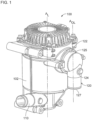
- FIG. 1 is a perspective view of a crankcase ventilation system 100, according to an embodiment.
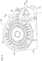
- FIG. 2 is a top cross-section view of a portion of the crankcase ventilation system 100.
- the crankcase ventilation system 100 comprises a housing 102 defining an internal volume structured to receive a rotating coalescer element 130. As shown in FIGS. 2-3 , rotating coalescer element 130 is positioned within the internal volume.
- the rotating coalescer element 130 may comprise a separating device 132, a first endcap 134 and a second endcap 136.
- the separating device 132 may comprise a stack of separating plates positioned between the first end cap 134 and the second endcap 136.
- the crankcase ventilation system 100 may include any other oil separator, for example, a stacked disc type air/oil separator.
- stacked disc type air/oil separators may include a stack of separation discs (e.g., a stack of frustoconical separation discs) supported by a shaft connected to a rotation turbine or motor included in the crankcase ventilation system. Spacing members may be positioned between each of the separation discs so as to form flow channels therebetween.
- the housing 102 includes a housing inlet 1 10 structured to receive a fluid (e.g., blowby gases), and a housing outlet 1 12 defined tangentially on a sidewall of the housing 102.
- the housing outlet 112 is structured to allow the fluid (e.g., filtered air with aerosols and oils removed therefrom) to exit the housing 102.
- the rotating coalescer element 130 may be rotated via an electric motor, hydraulic force, pneumatic force, gears, belts, pulleys etc., so as to drive the fluid through the internal volume of the housing 102 via centrifugal force. Rotation of the rotating coalescer element 130 may impart a rotational flow to the fluid flowing through the housing 102.
- An outlet conduit 120 is fluidly coupled to housing outlet 112.
- the outlet conduit 120 comprises an outlet conduit first portion 122 axially aligned with the housing outlet 112.
- the outlet conduit 120 also comprises an outlet conduit second portion 124 positioned downstream of the outlet conduit first portion 122, and perpendicular thereto such that an outlet conduit second portion longitudinal axis A OL is a parallel to a longitudinal axis A L of the housing 102 and offset therefrom. While the outlet conduit second portion 124 is shown in FIGS. 1-3 as being perpendicular to the outlet conduit first portion 122, in other embodiments, the outlet conduit second portion 124 may extend from the outlet conduit first portion 122 at a different angle relative to a flow axis of the fluid entering the outlet conduit first portion 122.
- FIG. 2 shows a baffle 126, according to a particular embodiment positioned in the outlet conduit second portion 124 of the outlet conduit 120.
- the baffle 126 is structured to disrupt a swirling flow of the fluid into the outlet conduit 120 so as to reduce a pressure drop experienced by the fluid as the fluid flows from the housing 102 into the outlet conduit 120.
- the baffle 126 comprises a vertical plate positioned in the outlet conduit second portion 124. Expanding further, the baffle 126 extends in a first direction from a first end 125 (shown in FIG. 1 ) of the outlet conduit second portion 124 proximal to the outlet conduit first portion 122 along the outlet conduit second portion longitudinal axis A OL towards an outlet conduit outlet 127, so as to define a baffle height h.
- the baffle height h of the baffle 126 is less than a length of the outlet conduit second portion 124.
- the baffle 126 extends in a second direction from a backwall of the outlet conduit second portion 124 towards the housing outlet 112 so as to define a baffle length l.
- the baffle length 1 of the baffle 126 is less than a width of the outlet conduit second portion 124.
- the baffle 126 may be integrally formed with the outlet conduit second portion 124, or the baffle 126 may include a separate vertical plate positioned within the outlet conduit second portion 124.
- perforations, openings, slots, louvers, ribs protrusions, or any other suitable features or a combination thereof may be formed on the baffle 126, or any other baffle described herein so as to facilitate reduction in the pressure drop of the fluid.
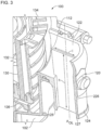
- FIG. 3 shows a baffle 226 according to another embodiment positioned in the outlet conduit second portion 124 of the crankcase ventilation system 100.
- the baffle 226 also comprises a vertical plate positioned in the outlet conduit second portion 124 similar to the baffle 126.
- the baffle 226 has a height h equal to the length of the outlet conduit second portion 124, and a length 1 equal to a width of the outlet conduit second portion 124.
- At a least a portion of the baffle 226 positioned proximate to the outlet conduit first portion 122 extends along the length l thereof into the outlet conduit first portion 122, for example, to the housing outlet 112.
- a slot 128 may be provided in a sidewall of the outlet conduit second portion 124.
- the slot 128 may be structured to receive an edge of the baffle 126 so as to position and/or secure the baffle 126 within the outlet conduit second portion 124.
- the baffle 226 may provide a substantially higher reduction in pressure drop relative to the baffle 126, for example, a reduction in pressure drop of up to 20% relative to a pressure drops in the fluid flow when no swirl breaking structure is present in the outlet conduit 120.
- FIG. 4 is a side cross-section view of an outlet conduit 320, according to a particular embodiment.
- the outlet conduit 320 may be used with the crankcase ventilation system 100 or any other crankcase ventilation system described herein.
- the outlet conduit 320 comprises a swirl breaking structure 326 positioned at an outlet conduit inlet 321 which is structured to receive a fluid (e.g., from the crankcase ventilation system 100).
- the swirl breaking structure 326 comprises a mesh (e.g., a wire mesh) or a grid.
- FIG. 5 is a top cross-section view of an outlet conduit 420, according to another embodiment.
- the outlet conduit 420 comprises an outlet conduit inlet 421 fluidly coupled to a housing 402, which may be substantially similar to the housing 102 previously described herein.
- the outlet conduit 420 comprises an outlet conduit first portion 422 and an outlet conduit second portion 424.
- a baffle 426 for breaking swirls in a fluid flow into the outlet conduit 420 is positioned on a backwall of the outlet conduit second portion 424 and extends towards the outlet conduit inlet 421.
- the baffle 426 is structured as a wedge such that the baffle 426 includes one or more curved surfaces.
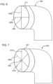
- FIG. 6 is a side cross-section view of an outlet conduit 520, according to yet another embodiment.
- the outlet conduit 520 may be used with the crankcase ventilation system 100 or any other crankcase ventilation system described herein.
- the outlet conduit 520 comprises a swirl breaking structure 526 positioned at an outlet conduit inlet 521 which is structured to receive a fluid (e.g., from the crankcase ventilation system 100).
- the swirl breaking structure 526 comprises a first plate 526a positioned horizontally, and a second plate 526b positioned vertically in the outlet conduit inlet 521such that the first plate 526a and the second plate 526b intersect at their midpoints so as to form a cross shape.
- FIG. 7 is a side cross-section view of an outlet conduit 620, according to still another embodiment.
- the outlet conduit 620 may be used with the crankcase ventilation system 100 or any other crankcase ventilation system described herein.
- the outlet conduit 620 comprises a swirl breaking structure 626 positioned at an outlet conduit inlet 621 which is structured to receive a fluid (e.g., from the crankcase ventilation system 100).
- the swirl breaking structure 626 comprises a first plate 626a positioned vertically in the outlet conduit inlet 621.
- the swirl breaking structure 626 further comprises a second plate 626b positioned diagonally at a first angle in the outlet conduit inlet 621, and a third plate 626c, also positioned diagonally in the outlet conduit inlet 621 at a second angle to the second plate 626b.
- the first plate 626a, the second plate 626b and the third plate 626c intersect at their respective midpoints.
- FIG. 8 is a side cross-section view of an outlet conduit 720, according to yet another embodiment.
- the outlet conduit 720 may be used with the crankcase ventilation system 100 or any other crankcase ventilation system described herein.
- the outlet conduit 720 comprises a swirl breaking structure 726 positioned at an outlet conduit inlet 721 which is structured to receive a fluid (e.g., from the crankcase ventilation system 100).
- the swirl breaking structure 726 comprises a first plate 726a positioned diagonally at a first angle in the outlet conduit inlet 721, and a second plate 726b also positioned diagonally in the outlet conduit inlet 721 perpendicular to the first plate 726a, such that the first plate 726a and the second plate 726b intersect at their respective midpoints.
- FIG. 9 is a top cross-section view of an outlet conduit 820, according to another embodiment.
- the outlet conduit 820 comprises an outlet conduit inlet 821 fluidly coupled to a housing 802, which may be substantially similar to the housing 102 previously described herein.
- the outlet conduit 820 comprises an outlet conduit first portion 822 and an outlet conduit second portion 824.
- a baffle 826 for breaking swirls in a fluid flowing into the outlet conduit 820 is positioned on a backwall of the outlet conduit second portion 824 and extends at an angle ⁇ with respect to a flow axis of the fluid entering the outlet conduit first portion 822 towards the outlet conduit inlet 821 from the backwall.
- FIG. 10 is a side cross-section view of an outlet conduit 920, according to yet another embodiment.
- the outlet conduit 920 comprises an outlet conduit inlet 921 structured to be fluidly coupled to a housing, for example, the housing 102 previously described herein.
- the outlet conduit 920 comprises an outlet conduit first portion 922 and an outlet conduit second portion 924.
- a baffle 926 for breaking swirls in a fluid flowing into the outlet conduit 920 is positioned on a backwall of the outlet conduit second portion 924.
- the baffle 926 extends in a first direction from proximate to a first end 925 of the outlet conduit second portion 924 along an outlet conduit second portion longitudinal axis towards an outlet conduit outlet 927, and in a second direction towards the outlet conduit inlet 921 .
- a baffle edge 928 of the baffle facing the first end 925 is inclined at an angle ⁇ with respect to a flow axis of the fluid entering the outlet conduit inlet 921.
- the baffle edge 928 may define a curve (e.g., concave, convex or any other curvature).
- FIG. 11 is a side cross-section view of an outlet conduit 1020, according to still another embodiment.
- the outlet conduit 1020 comprises an outlet conduit inlet 1021 structured to be fluidly coupled to a housing, for example, the housing 102 previously described herein.
- the outlet conduit 1020 comprises an outlet conduit first portion 1022 and an outlet conduit second portion 1024.
- a baffle 1026 is positioned in the outlet conduit second portion 1024 and extends from a first end 1025 of the outlet conduit first portion 1022 proximate to the outlet conduit second portion 1024 towards an outlet conduit outlet 1027.
- a baffle slit 1029 is defined in the baffle 1026, for example, axially aligned with a flow axis of the fluid flowing into the outlet conduit 1020 or at any other location, such that the baffle 1026 has a baffle first portion 1026a positioned proximate to the first end 1025, and a baffle second portion 1026b positioned below the baffle first portion 1026a, with the baffle slit 1029 defined therebetween.
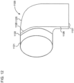
- FIG. 12 is a side cross-section view of an outlet conduit 1120, according to a particular embodiment.
- the outlet conduit 1120 comprises an outlet conduit inlet 1121 structured to be fluidly coupled to a housing, for example, the housing 102 previously described herein.
- the outlet conduit 1120 comprises an outlet conduit first portion 1122 and an outlet conduit second portion 1124.
- a baffle 1126 for breaking swirls in a fluid flowing into the outlet conduit 1120 is positioned on a backwall of the outlet conduit second portion 1124.
- the baffle 1126 extends in a first direction from a first end 1125 of the outlet conduit second portion 1124 along an outlet conduit second portion longitudinal axis towards an outlet conduit outlet 1127, and in a second direction towards the outlet conduit inlet 1121.
- a baffle edge 1128 of the baffle 1126 facing the outlet conduit inlet 1121 defines a curvature (e.g., an arc or a taper) towards the outlet conduit inlet 1121, such that that the baffle edge 1128 may curve into the outlet conduit first portion 1122.
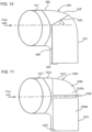
- FIGS. 13-15 are CFD simulations showing the fluid flow pathlines, total pressure drop pathlines, and velocity magnitude pathlines, respectively of a fluid flowing through the crankcase ventilation system 100 of FIG. 1 with no baffle, with the baffle of FIG. 2 (baffle 126), and the baffle of FIG. 3 (baffle 226) positioned in an outlet conduit thereof.
- the swirl in the fluid flow entering and flowing through the outlet conduit 120 is significantly reduced by including the baffle 126 in the outlet conduit 120 and even further reduced by including the baffle 226 in the outlet conduit 120.
- the reduction in pressure drop by including the baffle 226 in the outlet conduit 120 may be up to 20%.
- a member is intended to mean a single member or a combination of members
- a material is intended to mean one or more materials, or a combination thereof.
- Coupled means the joining of two members directly or indirectly to one another. Such joining may be stationary (e.g., permanent) or moveable (e.g., removable or releasable). Such joining may be achieved with the two members or the two members and any additional intermediate members being integrally formed as a single unitary body with one another or with the two members or the two members and any additional intermediate members being attached to one another.
Landscapes
- Engineering & Computer Science (AREA)
- Mechanical Engineering (AREA)
- General Engineering & Computer Science (AREA)
- Chemical & Material Sciences (AREA)
- Chemical Kinetics & Catalysis (AREA)
- Lubrication Details And Ventilation Of Internal Combustion Engines (AREA)
Claims (15)
- Auslassleitung (120, 320, 420, 520, 620, 720, 820, 920, 1020, 1120) für ein Gehäuse (102) eines sich drehenden Luft-/Öl-Abscheideelements (130), wobei die Auslassleitung Folgendes umfasst:einen ersten Auslassleitungsabschnitt (122, 322, 822, 1022, 1122), der einen Auslassleitungseinlass (321, 421, 521, 621, 721, 821, 921, 1021, 1121) aufweist, der dafür konfiguriert ist, fluidmäßig an einen Gehäuseauslass (112) gekoppelt zu werden, der tangential in einer Seitenwand des Gehäuses definiert ist, so dass der erste Auslassleitungsabschnitt in Axialrichtung mit dem Gehäuseauslass ausgerichtet ist, wobei der erste Auslassleitungsabschnitt dafür konfiguriert ist, Fluid aufzunehmen, das aus dem Gehäuseauslass ausgestoßen wird;einen zweiten Auslassleitungsabschnitt (124, 424, 824, 924, 1024, 1124), der stromabwärts von dem ersten Auslassleitungsabschnitt angeordnet ist, wobei der zweite Auslassleitungsabschnitt senkrecht zu dem ersten Auslassleitungsabschnitt ist; undeine Wirbelunterbrechungsstruktur, die in dem zweiten Auslassleitungsabschnitt angeordnet ist, wobei die Wirbelunterbrechungsstruktur dafür konfiguriert ist, eine Wirbelströmung des Fluids in die Auslassleitung zu unterbrechen, um so einen Druckabfall zu verringern, der durch das Fluid erfahren wird, während das Fluid aus dem Gehäuse in die Auslassleitung strömt;wobei die Wirbelunterbrechungsstruktur eine Ablenkfläche (126, 226, 426, 926, 1026, 1126) umfasst, wobei die Ablenkfläche eine in dem zweiten Auslassleitungsabschnitt angeordnete Platte umfasst und sich in einer ersten Richtung entlang einer Längsachse des zweiten Auslassleitungsabschnitts von einem ersten Ende des zweiten Auslassleitungsabschnitts nahe dem ersten Auslassleitungsabschnitt, hin zu einem Auslassleitungsauslass (127, 927, 1027, 1127) erstreckt, um eine Ablenkflächenhöhe (h) zu definieren, wobei die Ablenkflächenhöhe geringer als eine Höhe des zweiten Auslassleitungsabschnitts oder gleich derselben ist.
- Auslassleitung nach Anspruch 1, wobei sich die Ablenkfläche in einer zweiten Richtung von einer Rückwand des zweiten Auslassleitungsabschnitts hin zu dem Auslassleitungseinlass erstreckt, um eine Ablenkflächenlänge (l) zu definieren, wobei die Ablenkflächenlänge geringer als eine Breite des zweiten Auslassleitungsabschnitts oder gleich derselben ist.
- Auslassleitung nach Anspruch 1, wobei sich die Ablenkfläche von einer Rückwand des zweiten Auslassleitungsabschnitts in einem Winkel (α) in Bezug auf eine Strömungsachse des Fluids, das in den ersten Auslassleitungsabschnitt eintritt, hin zu dem Auslassleitungseinlass erstreckt.
- Auslassleitung nach Anspruch 1, wobei die Ablenkfläche eine Ablenkflächenkante (928) umfasst, die einem ersten Ende des zweiten Auslassleitungsabschnitts nahe dem ersten Auslassleitungsabschnitt gegenüberliegt, wobei die Ablenkflächenkante in einem Winkel (β) in Bezug auf eine Strömungsachse des Fluids, das in den Auslassleitungseinlass eintritt, geneigt ist; oder wobei
die Ablenkfläche eine Ablenkflächenkante (1128) umfasst, die dem Auslassleitungseinlass gegenüberliegt, wobei die Ablenkflächenkante eine Krümmung hin zu dem Auslassleitungseinlass definiert. - Auslassleitung nach Anspruch 1, wobei ein Ablenkflächenschlitz in der Ablenkfläche definiert ist, wobei der Ablenkflächenschlitz (1029) die Ablenkfläche in einen ersten Ablenkflächenabschnitt (1026a), der nahe einem ersten Ende des ersten Auslassleitungsabschnitts angeordnet ist, das dem zweiten Auslassleitungsabschnitt nahe ist, und einen zweiten Ablenkflächenabschnitt (1026b), der distal von dem ersten Auslassleitungsabschnitt angeordnet ist, teilt.
- Auslassleitung nach Anspruch 1, wobei die Wirbelunterbrechungsstruktur ein Gitter (326) umfasst, das an dem Auslassleitungseinlass angeordnet ist.
- Auslassleitung nach Anspruch 1, wobei die Wirbelunterbrechungsstruktur Platten (426a-b, 526a-b, 626a-b, 726a-b) umfasst, die an dem Auslassleitungseinlass angeordnet sind, wobei axiale Enden jeder der Platten an einen Rand des Auslassleitungseinlasses gekoppelt sind, wobei sich die Platten an Mittelpunkten derselben überschneiden.
- Kurbelgehäuse-Lüftungssystem, das Folgendes umfasst:ein Gehäuse (102), das ein inneres Volumen definiert, das dafür strukturiert ist, ein sich drehendes Luft-/Öl-Abscheideelement (130) aufzunehmen, wobei das Gehäuse einen Gehäuseeinlass (110), der dafür strukturiert ist, ein Fluid aufzunehmen, und einen Gehäuseauslass (112), der tangential in einer Seitenwand des Gehäuses definiert ist, aufweist, wobei der Gehäuseauslass dafür strukturiert ist, dass Fluid aus dem Gehäuse austritt, undeine Auslassleitung (120, 320, 420, 520, 620, 720, 820, 920, 1020, 1120) nach Anspruch 7, wobei der Auslassleitungseinlass des ersten Auslassleitungsabschnitts (122, 422, 822, 1022, 1122) fluidmäßig an den Gehäuseauslass gekoppelt ist.
- Kurbelgehäuse-Lüftungssystem nach Anspruch 8, wobei sich die Ablenkfläche in einer zweiten Richtung von einer Rückwand des zweiten Auslassleitungsabschnitts hin zu dem Auslassleitungseinlass erstreckt, um eine Ablenkflächenlänge zu definieren, wobei die Ablenkflächenlänge geringer als eine Breite des zweiten Auslassleitungsabschnitts oder gleich derselben ist.
- Kurbelgehäuse-Lüftungssystem nach Anspruch 8, wobei sich die Ablenkfläche von einer Rückwand des zweiten Auslassleitungsabschnitts in einem Winkel in Bezug auf eine Strömungsachse des Fluids, das in den ersten Auslassleitungsabschnitt eintritt, hin zu dem Auslassleitungseinlass erstreckt.
- Kurbelgehäuse-Lüftungssystem nach Anspruch 8, wobei die Ablenkfläche eine Ablenkflächenkante umfasst, die einem ersten Ende des zweiten Auslassleitungsabschnitts nahe dem ersten Auslassleitungsabschnitt gegenüberliegt, wobei die Ablenkflächenkante in einem Winkel in Bezug auf eine Strömungsachse des Fluids, das in den Auslassleitungseinlass eintritt, geneigt ist.
- Kurbelgehäuse-Lüftungssystem nach Anspruch 8, wobei die Ablenkfläche eine Ablenkflächenkante umfasst, die dem Auslassleitungseinlass gegenüberliegt, wobei die Ablenkflächenkante eine Krümmung hin zu dem Auslassleitungseinlass definiert.
- Kurbelgehäuse-Lüftungssystem nach Anspruch 8, wobei ein Ablenkflächenschlitz in der Ablenkfläche definiert ist, wobei der Ablenkflächenschlitz die Ablenkfläche in einen ersten Ablenkflächenabschnitt, der nahe einem ersten Ende des ersten Auslassleitungsabschnitts angeordnet ist, das dem zweiten Auslassleitungsabschnitt nahe ist, und einen zweiten Ablenkflächenabschnitt, der distal von dem ersten Auslassleitungsabschnitt angeordnet ist, teilt.
- Kurbelgehäuse-Lüftungssystem nach Anspruch 8, wobei die Wirbelunterbrechungsstruktur ein Gitter umfasst, das an dem Auslassleitungseinlass angeordnet ist.
- Kurbelgehäuse-Lüftungssystem nach Anspruch 8, wobei die Wirbelunterbrechungsstruktur Platten umfasst, die an dem Auslassleitungseinlass angeordnet sind, wobei axiale Enden jeder der Platten an einen Rand des Auslassleitungseinlasses gekoppelt sind, wobei sich die Platten an Mittelpunkten derselben überschneiden.
Applications Claiming Priority (2)
| Application Number | Priority Date | Filing Date | Title |
|---|---|---|---|
| IN201741043739 | 2017-12-06 | ||
| PCT/US2018/060070 WO2019112755A1 (en) | 2017-12-06 | 2018-11-09 | Crankcase ventilation systems having a swirl breaker to reduce pressure drop in tangentially exiting fluids |
Publications (3)
| Publication Number | Publication Date |
|---|---|
| EP3720588A1 EP3720588A1 (de) | 2020-10-14 |
| EP3720588A4 EP3720588A4 (de) | 2021-08-18 |
| EP3720588B1 true EP3720588B1 (de) | 2023-08-30 |
Family
ID=66751080
Family Applications (1)
| Application Number | Title | Priority Date | Filing Date |
|---|---|---|---|
| EP18885642.1A Active EP3720588B1 (de) | 2017-12-06 | 2018-11-09 | Kurbelgehäuslüftungssysteme mit einem drallbrecher zur verringerung des druckabfalls bei tangential austretenden fluiden |
Country Status (4)
| Country | Link |
|---|---|
| US (1) | US11619152B2 (de) |
| EP (1) | EP3720588B1 (de) |
| CN (1) | CN111556781B (de) |
| WO (1) | WO2019112755A1 (de) |
Family Cites Families (42)
| Publication number | Priority date | Publication date | Assignee | Title |
|---|---|---|---|---|
| BE535905A (de) * | 1954-02-23 | |||
| BE636933A (de) * | 1962-09-05 | |||
| US4162904A (en) * | 1978-04-10 | 1979-07-31 | American Air Filter Company, Inc. | Silencer-separator device |
| US4187088A (en) * | 1979-01-18 | 1980-02-05 | Maloney-Crawford Corporation | Down flow centrifugal separator |
| US5277154A (en) | 1992-09-21 | 1994-01-11 | Mcdowell Alex R | Oil/air separator and method thereof |
| US6033450A (en) * | 1995-12-21 | 2000-03-07 | United Technologies Corporation | Deoiler shaft vortex separator |
| CN1220823C (zh) * | 2002-06-28 | 2005-09-28 | 周吉政 | 内燃发动机曲轴箱排气处理装置 |
| DE20211329U1 (de) * | 2002-07-26 | 2003-12-04 | Hengst Gmbh & Co.Kg | Ölabscheider zur Abscheidung von Öl aus dem Kurbelgehäuseentlüftungsgas einer Brennkraftmaschine |
| DE10251947A1 (de) * | 2002-11-08 | 2004-05-19 | Robert Bosch Gmbh | Vorrichtung zur Abscheidung von Flüssigkeit aus einem Gasstrom |
| GB2413974B (en) * | 2004-05-12 | 2008-02-13 | Dyson Ltd | Cyclonic separating apparatus |
| WO2007008772A2 (en) * | 2005-07-12 | 2007-01-18 | Bissell Homecare, Inc. | Vacuum cleaner with cyclonic dirt separation and vortex stabilizer |
| DE102005061256A1 (de) * | 2005-12-20 | 2007-06-21 | Günter Dr. Slowik | Verfahren und Vorrichtung zur Entölung von Kurbelgehäuseentlüftungsgasen einer Brennkraftmaschine |
| DE102006024820A1 (de) * | 2006-05-29 | 2007-12-13 | Mahle International Gmbh | Einrichtung zur Trennung eines Gas-Flüssigkeitsgemisches, insbesondere bei der Entlüftung eines Kurbelgehäuses eines Verbrennungsmotors |
| US7857883B2 (en) | 2007-10-17 | 2010-12-28 | Cummins Filtration Ip, Inc. | Inertial gas-liquid separator with constrictable and expansible nozzle valve sidewall |
| JP2009186370A (ja) * | 2008-02-07 | 2009-08-20 | Toshiba Corp | 冷却材炉心入口構造 |
| DE102008017919A1 (de) | 2008-04-08 | 2009-10-15 | Mann + Hummel Gmbh | Abscheider für eine Kurbelgehäuseentlüftung einer Brennkraftmaschine |
| CN102089411A (zh) * | 2008-07-10 | 2011-06-08 | 国际壳牌研究有限公司 | 从污染的气体物流中脱除气态污染物的方法 |
| CN101402073A (zh) | 2008-11-02 | 2009-04-08 | 江苏科行环境工程技术有限公司 | 一种粗、中、细粉多级选粉机 |
| CN201635799U (zh) * | 2009-10-30 | 2010-11-17 | 重庆长安汽车股份有限公司 | 一种集成油气结构的发动机汽缸盖罩及曲轴箱通风系统 |
| US9010994B2 (en) * | 2010-01-21 | 2015-04-21 | Fluid Components International Llc | Flow mixer and conditioner |
| US8807097B2 (en) * | 2010-01-27 | 2014-08-19 | Cummins Filtration Ip Inc. | Closed crankcase ventilation system |
| CN102195061A (zh) * | 2010-03-17 | 2011-09-21 | 中兴电工机械股份有限公司 | 增进主流道气体分布均匀的燃料电池电堆结构 |
| EP2598234B1 (de) * | 2010-07-30 | 2016-01-06 | EMD Millipore Corporation | Einweg-mischer |
| CN102588347A (zh) | 2011-01-10 | 2012-07-18 | 珠海格力电器股份有限公司 | 离心通风机及包含该离心通风机的空调器 |
| CN201954523U (zh) * | 2011-03-15 | 2011-08-31 | 昆明醋酸纤维有限公司 | 一种外置式锅炉汽水分离装置 |
| US8986539B2 (en) * | 2011-04-19 | 2015-03-24 | Cummins Filtration Ip Inc. | Inside-out flow filter with pressure recovery |
| US8439071B2 (en) | 2011-05-27 | 2013-05-14 | Johnson Screens, Inc. | Screen basket vortex breaker for vessel |
| BR112014009743A2 (pt) * | 2011-11-04 | 2017-05-02 | Cummins Filtration Ip Inc | separador giratório para separar líquido de mistura fluida |
| CN102824817B (zh) * | 2012-07-19 | 2014-10-29 | 天津大学 | 一种无导流板的环流进料分布器 |
| WO2014152527A1 (en) * | 2013-03-14 | 2014-09-25 | Duramax Marine, Llc | Turbulence enhancer for keel cooler |
| US9914090B2 (en) * | 2013-06-28 | 2018-03-13 | Uop Llc | Vapor-liquid contacting apparatuses and methods for removing contaminants from gas streams |
| GB201320305D0 (en) * | 2013-11-18 | 2014-01-01 | Nifco Uk Ltd | Apparatus for coalescing particles of a first fluid entrained in a flow of a second fluid |
| US10631697B2 (en) * | 2014-02-14 | 2020-04-28 | Techtronic Industries Co. Ltd. | Separator configuration |
| EP2939746B1 (de) * | 2014-04-30 | 2016-09-07 | Alfa Laval Corporate AB | Zentrifugalabscheider |
| CN104265403B (zh) * | 2014-09-29 | 2017-02-15 | 长城汽车股份有限公司 | 用于车辆的空气滤清器 |
| WO2016065148A2 (en) * | 2014-10-22 | 2016-04-28 | Techtronic Industries Co. Ltd. | Vacuum cleaner having cyclonic separator |
| EP3209175B1 (de) * | 2014-10-22 | 2023-01-04 | Techtronic Industries Co. Ltd. | Handstaubsauger |
| EP3050631B1 (de) * | 2015-02-02 | 2018-05-02 | Alfdex AB | Rotierender sekundärer Teiler |
| US10543442B2 (en) | 2015-03-30 | 2020-01-28 | Cummins Filtration Ip, Inc. | Multiple stage rotating coalescer devices |
| CN205191864U (zh) * | 2015-11-27 | 2016-04-27 | 深圳创维空调科技有限公司 | 一种天井机空调 |
| CN112901310B (zh) | 2016-04-28 | 2022-12-02 | 康明斯滤清系统知识产权公司 | 使气体通过空心轴排出的由内向外旋转聚结器 |
| US10918983B2 (en) * | 2018-06-16 | 2021-02-16 | Rafat A. Kerkonian | Pneumatic trap for collecting suspended particles dispersed in air or gas |
-
2018
- 2018-11-09 EP EP18885642.1A patent/EP3720588B1/de active Active
- 2018-11-09 US US16/769,655 patent/US11619152B2/en active Active
- 2018-11-09 WO PCT/US2018/060070 patent/WO2019112755A1/en not_active Ceased
- 2018-11-09 CN CN201880085121.7A patent/CN111556781B/zh active Active
Also Published As
| Publication number | Publication date |
|---|---|
| US11619152B2 (en) | 2023-04-04 |
| EP3720588A4 (de) | 2021-08-18 |
| CN111556781B (zh) | 2022-03-29 |
| US20210180486A1 (en) | 2021-06-17 |
| WO2019112755A1 (en) | 2019-06-13 |
| EP3720588A1 (de) | 2020-10-14 |
| CN111556781A (zh) | 2020-08-18 |
Similar Documents
| Publication | Publication Date | Title |
|---|---|---|
| US10543442B2 (en) | Multiple stage rotating coalescer devices | |
| US11964224B2 (en) | Rotating coalescing element with directed liquid drainage and gas outlet | |
| US20240173661A1 (en) | Systems and methods for rotating coalescers maintaining positive recirculation through a dynamic seal | |
| JP5519024B2 (ja) | 第2の流体の流れから第1の流体の粒子を分離するための分離システム | |
| CN112901310B (zh) | 使气体通过空心轴排出的由内向外旋转聚结器 | |
| US12330106B2 (en) | Split flow axial crankcase separator | |
| US20130312609A1 (en) | Apparatus and methods for filtration of solid particles and separation of liquid droplets and liquid aerosols from a gas stream | |
| EP3103554B1 (de) | Zentrifugalabscheider | |
| CN108290097A (zh) | 用于清洁气体的分离器装置 | |
| CN111315466A (zh) | 曲轴箱通风中的油管理结构 | |
| CN115324685B (zh) | 一种离心式分离器和发动机系统 | |
| US11619152B2 (en) | Crankcase ventilation systems having a swirl breaker to reduce pressure drop in tangentially exiting fluids | |
| US20150135662A1 (en) | Apparatus for Coalescing Particles of a First Fluid Entrained in a Flow of a Second Fluid | |
| KR20210018515A (ko) | 공기/액체 분리를 위한 스태거형 어레이 배열 | |
| WO2025207589A1 (en) | Drainage system for rotating crankcase ventilation systems |
Legal Events
| Date | Code | Title | Description |
|---|---|---|---|
| STAA | Information on the status of an ep patent application or granted ep patent |
Free format text: STATUS: THE INTERNATIONAL PUBLICATION HAS BEEN MADE |
|
| PUAI | Public reference made under article 153(3) epc to a published international application that has entered the european phase |
Free format text: ORIGINAL CODE: 0009012 |
|
| STAA | Information on the status of an ep patent application or granted ep patent |
Free format text: STATUS: REQUEST FOR EXAMINATION WAS MADE |
|
| 17P | Request for examination filed |
Effective date: 20200703 |
|
| AK | Designated contracting states |
Kind code of ref document: A1 Designated state(s): AL AT BE BG CH CY CZ DE DK EE ES FI FR GB GR HR HU IE IS IT LI LT LU LV MC MK MT NL NO PL PT RO RS SE SI SK SM TR |
|
| AX | Request for extension of the european patent |
Extension state: BA ME |
|
| DAV | Request for validation of the european patent (deleted) | ||
| DAX | Request for extension of the european patent (deleted) | ||
| A4 | Supplementary search report drawn up and despatched |
Effective date: 20210716 |
|
| RIC1 | Information provided on ipc code assigned before grant |
Ipc: F01M 13/04 20060101AFI20210712BHEP Ipc: F01M 13/00 20060101ALI20210712BHEP Ipc: B01D 45/12 20060101ALI20210712BHEP Ipc: B01D 45/06 20060101ALI20210712BHEP Ipc: B01D 45/08 20060101ALI20210712BHEP |
|
| REG | Reference to a national code |
Ref country code: DE Ref legal event code: R079 Free format text: PREVIOUS MAIN CLASS: B01D0045120000 Ipc: F01M0013040000 Ref country code: DE Ref legal event code: R079 Ref document number: 602018056723 Country of ref document: DE Free format text: PREVIOUS MAIN CLASS: B01D0045120000 Ipc: F01M0013040000 |
|
| RIC1 | Information provided on ipc code assigned before grant |
Ipc: B01D 45/08 20060101ALI20221109BHEP Ipc: B01D 45/06 20060101ALI20221109BHEP Ipc: B01D 45/12 20060101ALI20221109BHEP Ipc: F01M 13/00 20060101ALI20221109BHEP Ipc: F01M 13/04 20060101AFI20221109BHEP |
|
| GRAP | Despatch of communication of intention to grant a patent |
Free format text: ORIGINAL CODE: EPIDOSNIGR1 |
|
| STAA | Information on the status of an ep patent application or granted ep patent |
Free format text: STATUS: GRANT OF PATENT IS INTENDED |
|
| INTG | Intention to grant announced |
Effective date: 20221220 |
|
| GRAJ | Information related to disapproval of communication of intention to grant by the applicant or resumption of examination proceedings by the epo deleted |
Free format text: ORIGINAL CODE: EPIDOSDIGR1 |
|
| STAA | Information on the status of an ep patent application or granted ep patent |
Free format text: STATUS: REQUEST FOR EXAMINATION WAS MADE |
|
| GRAP | Despatch of communication of intention to grant a patent |
Free format text: ORIGINAL CODE: EPIDOSNIGR1 |
|
| STAA | Information on the status of an ep patent application or granted ep patent |
Free format text: STATUS: GRANT OF PATENT IS INTENDED |
|
| INTC | Intention to grant announced (deleted) | ||
| INTG | Intention to grant announced |
Effective date: 20230320 |
|
| P01 | Opt-out of the competence of the unified patent court (upc) registered |
Effective date: 20230510 |
|
| GRAS | Grant fee paid |
Free format text: ORIGINAL CODE: EPIDOSNIGR3 |
|
| GRAA | (expected) grant |
Free format text: ORIGINAL CODE: 0009210 |
|
| STAA | Information on the status of an ep patent application or granted ep patent |
Free format text: STATUS: THE PATENT HAS BEEN GRANTED |
|
| AK | Designated contracting states |
Kind code of ref document: B1 Designated state(s): AL AT BE BG CH CY CZ DE DK EE ES FI FR GB GR HR HU IE IS IT LI LT LU LV MC MK MT NL NO PL PT RO RS SE SI SK SM TR |
|
| REG | Reference to a national code |
Ref country code: GB Ref legal event code: FG4D |
|
| REG | Reference to a national code |
Ref country code: CH Ref legal event code: EP |
|
| REG | Reference to a national code |
Ref country code: DE Ref legal event code: R096 Ref document number: 602018056723 Country of ref document: DE |
|
| REG | Reference to a national code |
Ref country code: IE Ref legal event code: FG4D |
|
| REG | Reference to a national code |
Ref country code: SE Ref legal event code: TRGR |
|
| REG | Reference to a national code |
Ref country code: LT Ref legal event code: MG9D |
|
| REG | Reference to a national code |
Ref country code: NL Ref legal event code: MP Effective date: 20230830 |
|
| REG | Reference to a national code |
Ref country code: AT Ref legal event code: MK05 Ref document number: 1605711 Country of ref document: AT Kind code of ref document: T Effective date: 20230830 |
|
| PG25 | Lapsed in a contracting state [announced via postgrant information from national office to epo] |
Ref country code: GR Free format text: LAPSE BECAUSE OF FAILURE TO SUBMIT A TRANSLATION OF THE DESCRIPTION OR TO PAY THE FEE WITHIN THE PRESCRIBED TIME-LIMIT Effective date: 20231201 |
|
| PG25 | Lapsed in a contracting state [announced via postgrant information from national office to epo] |
Ref country code: IS Free format text: LAPSE BECAUSE OF FAILURE TO SUBMIT A TRANSLATION OF THE DESCRIPTION OR TO PAY THE FEE WITHIN THE PRESCRIBED TIME-LIMIT Effective date: 20231230 |
|
| PG25 | Lapsed in a contracting state [announced via postgrant information from national office to epo] |
Ref country code: RS Free format text: LAPSE BECAUSE OF FAILURE TO SUBMIT A TRANSLATION OF THE DESCRIPTION OR TO PAY THE FEE WITHIN THE PRESCRIBED TIME-LIMIT Effective date: 20230830 Ref country code: NO Free format text: LAPSE BECAUSE OF FAILURE TO SUBMIT A TRANSLATION OF THE DESCRIPTION OR TO PAY THE FEE WITHIN THE PRESCRIBED TIME-LIMIT Effective date: 20231130 Ref country code: LV Free format text: LAPSE BECAUSE OF FAILURE TO SUBMIT A TRANSLATION OF THE DESCRIPTION OR TO PAY THE FEE WITHIN THE PRESCRIBED TIME-LIMIT Effective date: 20230830 Ref country code: LT Free format text: LAPSE BECAUSE OF FAILURE TO SUBMIT A TRANSLATION OF THE DESCRIPTION OR TO PAY THE FEE WITHIN THE PRESCRIBED TIME-LIMIT Effective date: 20230830 Ref country code: IS Free format text: LAPSE BECAUSE OF FAILURE TO SUBMIT A TRANSLATION OF THE DESCRIPTION OR TO PAY THE FEE WITHIN THE PRESCRIBED TIME-LIMIT Effective date: 20231230 Ref country code: HR Free format text: LAPSE BECAUSE OF FAILURE TO SUBMIT A TRANSLATION OF THE DESCRIPTION OR TO PAY THE FEE WITHIN THE PRESCRIBED TIME-LIMIT Effective date: 20230830 Ref country code: GR Free format text: LAPSE BECAUSE OF FAILURE TO SUBMIT A TRANSLATION OF THE DESCRIPTION OR TO PAY THE FEE WITHIN THE PRESCRIBED TIME-LIMIT Effective date: 20231201 Ref country code: FI Free format text: LAPSE BECAUSE OF FAILURE TO SUBMIT A TRANSLATION OF THE DESCRIPTION OR TO PAY THE FEE WITHIN THE PRESCRIBED TIME-LIMIT Effective date: 20230830 Ref country code: AT Free format text: LAPSE BECAUSE OF FAILURE TO SUBMIT A TRANSLATION OF THE DESCRIPTION OR TO PAY THE FEE WITHIN THE PRESCRIBED TIME-LIMIT Effective date: 20230830 |
|
| PG25 | Lapsed in a contracting state [announced via postgrant information from national office to epo] |
Ref country code: PL Free format text: LAPSE BECAUSE OF FAILURE TO SUBMIT A TRANSLATION OF THE DESCRIPTION OR TO PAY THE FEE WITHIN THE PRESCRIBED TIME-LIMIT Effective date: 20230830 Ref country code: NL Free format text: LAPSE BECAUSE OF FAILURE TO SUBMIT A TRANSLATION OF THE DESCRIPTION OR TO PAY THE FEE WITHIN THE PRESCRIBED TIME-LIMIT Effective date: 20230830 |
|
| PG25 | Lapsed in a contracting state [announced via postgrant information from national office to epo] |
Ref country code: ES Free format text: LAPSE BECAUSE OF FAILURE TO SUBMIT A TRANSLATION OF THE DESCRIPTION OR TO PAY THE FEE WITHIN THE PRESCRIBED TIME-LIMIT Effective date: 20230830 |
|
| PG25 | Lapsed in a contracting state [announced via postgrant information from national office to epo] |
Ref country code: SM Free format text: LAPSE BECAUSE OF FAILURE TO SUBMIT A TRANSLATION OF THE DESCRIPTION OR TO PAY THE FEE WITHIN THE PRESCRIBED TIME-LIMIT Effective date: 20230830 Ref country code: RO Free format text: LAPSE BECAUSE OF FAILURE TO SUBMIT A TRANSLATION OF THE DESCRIPTION OR TO PAY THE FEE WITHIN THE PRESCRIBED TIME-LIMIT Effective date: 20230830 Ref country code: ES Free format text: LAPSE BECAUSE OF FAILURE TO SUBMIT A TRANSLATION OF THE DESCRIPTION OR TO PAY THE FEE WITHIN THE PRESCRIBED TIME-LIMIT Effective date: 20230830 Ref country code: EE Free format text: LAPSE BECAUSE OF FAILURE TO SUBMIT A TRANSLATION OF THE DESCRIPTION OR TO PAY THE FEE WITHIN THE PRESCRIBED TIME-LIMIT Effective date: 20230830 Ref country code: DK Free format text: LAPSE BECAUSE OF FAILURE TO SUBMIT A TRANSLATION OF THE DESCRIPTION OR TO PAY THE FEE WITHIN THE PRESCRIBED TIME-LIMIT Effective date: 20230830 Ref country code: CZ Free format text: LAPSE BECAUSE OF FAILURE TO SUBMIT A TRANSLATION OF THE DESCRIPTION OR TO PAY THE FEE WITHIN THE PRESCRIBED TIME-LIMIT Effective date: 20230830 Ref country code: SK Free format text: LAPSE BECAUSE OF FAILURE TO SUBMIT A TRANSLATION OF THE DESCRIPTION OR TO PAY THE FEE WITHIN THE PRESCRIBED TIME-LIMIT Effective date: 20230830 Ref country code: PT Free format text: LAPSE BECAUSE OF FAILURE TO SUBMIT A TRANSLATION OF THE DESCRIPTION OR TO PAY THE FEE WITHIN THE PRESCRIBED TIME-LIMIT Effective date: 20240102 |
|
| PG25 | Lapsed in a contracting state [announced via postgrant information from national office to epo] |
Ref country code: IT Free format text: LAPSE BECAUSE OF FAILURE TO SUBMIT A TRANSLATION OF THE DESCRIPTION OR TO PAY THE FEE WITHIN THE PRESCRIBED TIME-LIMIT Effective date: 20230830 |
|
| REG | Reference to a national code |
Ref country code: DE Ref legal event code: R097 Ref document number: 602018056723 Country of ref document: DE |
|
| REG | Reference to a national code |
Ref country code: CH Ref legal event code: PL |
|
| PG25 | Lapsed in a contracting state [announced via postgrant information from national office to epo] |
Ref country code: MC Free format text: LAPSE BECAUSE OF FAILURE TO SUBMIT A TRANSLATION OF THE DESCRIPTION OR TO PAY THE FEE WITHIN THE PRESCRIBED TIME-LIMIT Effective date: 20230830 |
|
| PLBE | No opposition filed within time limit |
Free format text: ORIGINAL CODE: 0009261 |
|
| STAA | Information on the status of an ep patent application or granted ep patent |
Free format text: STATUS: NO OPPOSITION FILED WITHIN TIME LIMIT |
|
| PG25 | Lapsed in a contracting state [announced via postgrant information from national office to epo] |
Ref country code: LU Free format text: LAPSE BECAUSE OF NON-PAYMENT OF DUE FEES Effective date: 20231109 |
|
| PG25 | Lapsed in a contracting state [announced via postgrant information from national office to epo] |
Ref country code: CH Free format text: LAPSE BECAUSE OF NON-PAYMENT OF DUE FEES Effective date: 20231130 |
|
| GBPC | Gb: european patent ceased through non-payment of renewal fee |
Effective date: 20231130 |
|
| PG25 | Lapsed in a contracting state [announced via postgrant information from national office to epo] |
Ref country code: MC Free format text: LAPSE BECAUSE OF FAILURE TO SUBMIT A TRANSLATION OF THE DESCRIPTION OR TO PAY THE FEE WITHIN THE PRESCRIBED TIME-LIMIT Effective date: 20230830 Ref country code: LU Free format text: LAPSE BECAUSE OF NON-PAYMENT OF DUE FEES Effective date: 20231109 Ref country code: CH Free format text: LAPSE BECAUSE OF NON-PAYMENT OF DUE FEES Effective date: 20231130 Ref country code: SI Free format text: LAPSE BECAUSE OF FAILURE TO SUBMIT A TRANSLATION OF THE DESCRIPTION OR TO PAY THE FEE WITHIN THE PRESCRIBED TIME-LIMIT Effective date: 20230830 |
|
| REG | Reference to a national code |
Ref country code: BE Ref legal event code: MM Effective date: 20231130 |
|
| 26N | No opposition filed |
Effective date: 20240603 |
|
| REG | Reference to a national code |
Ref country code: IE Ref legal event code: MM4A |
|
| PG25 | Lapsed in a contracting state [announced via postgrant information from national office to epo] |
Ref country code: IE Free format text: LAPSE BECAUSE OF NON-PAYMENT OF DUE FEES Effective date: 20231109 |
|
| PG25 | Lapsed in a contracting state [announced via postgrant information from national office to epo] |
Ref country code: GB Free format text: LAPSE BECAUSE OF NON-PAYMENT OF DUE FEES Effective date: 20231130 |
|
| PG25 | Lapsed in a contracting state [announced via postgrant information from national office to epo] |
Ref country code: BE Free format text: LAPSE BECAUSE OF NON-PAYMENT OF DUE FEES Effective date: 20231130 |
|
| PG25 | Lapsed in a contracting state [announced via postgrant information from national office to epo] |
Ref country code: IE Free format text: LAPSE BECAUSE OF NON-PAYMENT OF DUE FEES Effective date: 20231109 Ref country code: GB Free format text: LAPSE BECAUSE OF NON-PAYMENT OF DUE FEES Effective date: 20231130 Ref country code: BE Free format text: LAPSE BECAUSE OF NON-PAYMENT OF DUE FEES Effective date: 20231130 |
|
| PG25 | Lapsed in a contracting state [announced via postgrant information from national office to epo] |
Ref country code: BG Free format text: LAPSE BECAUSE OF FAILURE TO SUBMIT A TRANSLATION OF THE DESCRIPTION OR TO PAY THE FEE WITHIN THE PRESCRIBED TIME-LIMIT Effective date: 20230830 |
|
| PG25 | Lapsed in a contracting state [announced via postgrant information from national office to epo] |
Ref country code: BG Free format text: LAPSE BECAUSE OF FAILURE TO SUBMIT A TRANSLATION OF THE DESCRIPTION OR TO PAY THE FEE WITHIN THE PRESCRIBED TIME-LIMIT Effective date: 20230830 |
|
| PG25 | Lapsed in a contracting state [announced via postgrant information from national office to epo] |
Ref country code: CY Free format text: LAPSE BECAUSE OF FAILURE TO SUBMIT A TRANSLATION OF THE DESCRIPTION OR TO PAY THE FEE WITHIN THE PRESCRIBED TIME-LIMIT; INVALID AB INITIO Effective date: 20181109 |
|
| PG25 | Lapsed in a contracting state [announced via postgrant information from national office to epo] |
Ref country code: HU Free format text: LAPSE BECAUSE OF FAILURE TO SUBMIT A TRANSLATION OF THE DESCRIPTION OR TO PAY THE FEE WITHIN THE PRESCRIBED TIME-LIMIT; INVALID AB INITIO Effective date: 20181109 |
|
| PG25 | Lapsed in a contracting state [announced via postgrant information from national office to epo] |
Ref country code: TR Free format text: LAPSE BECAUSE OF FAILURE TO SUBMIT A TRANSLATION OF THE DESCRIPTION OR TO PAY THE FEE WITHIN THE PRESCRIBED TIME-LIMIT Effective date: 20230830 |
|
| PGFP | Annual fee paid to national office [announced via postgrant information from national office to epo] |
Ref country code: DE Payment date: 20251118 Year of fee payment: 8 |
|
| PGFP | Annual fee paid to national office [announced via postgrant information from national office to epo] |
Ref country code: FR Payment date: 20251125 Year of fee payment: 8 |
|
| PGFP | Annual fee paid to national office [announced via postgrant information from national office to epo] |
Ref country code: SE Payment date: 20251119 Year of fee payment: 8 |