EP3720610B1 - Procédé de séparation d'une substance de l'eau - Google Patents
Procédé de séparation d'une substance de l'eau Download PDFInfo
- Publication number
- EP3720610B1 EP3720610B1 EP18886120.7A EP18886120A EP3720610B1 EP 3720610 B1 EP3720610 B1 EP 3720610B1 EP 18886120 A EP18886120 A EP 18886120A EP 3720610 B1 EP3720610 B1 EP 3720610B1
- Authority
- EP
- European Patent Office
- Prior art keywords
- chamber
- water
- flow
- froth layer
- froth
- Prior art date
- Legal status (The legal status is an assumption and is not a legal conclusion. Google has not performed a legal analysis and makes no representation as to the accuracy of the status listed.)
- Active
Links
Images






Classifications
-
- B—PERFORMING OPERATIONS; TRANSPORTING
- B03—SEPARATION OF SOLID MATERIALS USING LIQUIDS OR USING PNEUMATIC TABLES OR JIGS; MAGNETIC OR ELECTROSTATIC SEPARATION OF SOLID MATERIALS FROM SOLID MATERIALS OR FLUIDS; SEPARATION BY HIGH-VOLTAGE ELECTRIC FIELDS
- B03D—FLOTATION; DIFFERENTIAL SEDIMENTATION
- B03D1/00—Flotation
- B03D1/02—Froth-flotation processes
- B03D1/028—Control and monitoring of flotation processes; computer models therefor
-
- B—PERFORMING OPERATIONS; TRANSPORTING
- B03—SEPARATION OF SOLID MATERIALS USING LIQUIDS OR USING PNEUMATIC TABLES OR JIGS; MAGNETIC OR ELECTROSTATIC SEPARATION OF SOLID MATERIALS FROM SOLID MATERIALS OR FLUIDS; SEPARATION BY HIGH-VOLTAGE ELECTRIC FIELDS
- B03D—FLOTATION; DIFFERENTIAL SEDIMENTATION
- B03D1/00—Flotation
- B03D1/08—Subsequent treatment of concentrated product
-
- B—PERFORMING OPERATIONS; TRANSPORTING
- B03—SEPARATION OF SOLID MATERIALS USING LIQUIDS OR USING PNEUMATIC TABLES OR JIGS; MAGNETIC OR ELECTROSTATIC SEPARATION OF SOLID MATERIALS FROM SOLID MATERIALS OR FLUIDS; SEPARATION BY HIGH-VOLTAGE ELECTRIC FIELDS
- B03D—FLOTATION; DIFFERENTIAL SEDIMENTATION
- B03D1/00—Flotation
- B03D1/14—Flotation machines
- B03D1/1443—Feed or discharge mechanisms for flotation tanks
- B03D1/1462—Discharge mechanisms for the froth
-
- B—PERFORMING OPERATIONS; TRANSPORTING
- B03—SEPARATION OF SOLID MATERIALS USING LIQUIDS OR USING PNEUMATIC TABLES OR JIGS; MAGNETIC OR ELECTROSTATIC SEPARATION OF SOLID MATERIALS FROM SOLID MATERIALS OR FLUIDS; SEPARATION BY HIGH-VOLTAGE ELECTRIC FIELDS
- B03D—FLOTATION; DIFFERENTIAL SEDIMENTATION
- B03D1/00—Flotation
- B03D1/14—Flotation machines
- B03D1/24—Pneumatic
-
- C—CHEMISTRY; METALLURGY
- C02—TREATMENT OF WATER, WASTE WATER, SEWAGE, OR SLUDGE
- C02F—TREATMENT OF WATER, WASTE WATER, SEWAGE, OR SLUDGE
- C02F1/00—Treatment of water, waste water, or sewage
- C02F1/24—Treatment of water, waste water, or sewage by flotation
-
- C—CHEMISTRY; METALLURGY
- C02—TREATMENT OF WATER, WASTE WATER, SEWAGE, OR SLUDGE
- C02F—TREATMENT OF WATER, WASTE WATER, SEWAGE, OR SLUDGE
- C02F9/00—Multistage treatment of water, waste water or sewage
-
- B—PERFORMING OPERATIONS; TRANSPORTING
- B03—SEPARATION OF SOLID MATERIALS USING LIQUIDS OR USING PNEUMATIC TABLES OR JIGS; MAGNETIC OR ELECTROSTATIC SEPARATION OF SOLID MATERIALS FROM SOLID MATERIALS OR FLUIDS; SEPARATION BY HIGH-VOLTAGE ELECTRIC FIELDS
- B03D—FLOTATION; DIFFERENTIAL SEDIMENTATION
- B03D2203/00—Specified materials treated by the flotation agents; Specified applications
- B03D2203/008—Water purification, e.g. for process water recycling
-
- C—CHEMISTRY; METALLURGY
- C02—TREATMENT OF WATER, WASTE WATER, SEWAGE, OR SLUDGE
- C02F—TREATMENT OF WATER, WASTE WATER, SEWAGE, OR SLUDGE
- C02F1/00—Treatment of water, waste water, or sewage
- C02F1/28—Treatment of water, waste water, or sewage by sorption
- C02F1/283—Treatment of water, waste water, or sewage by sorption using coal, charred products, or inorganic mixtures containing them
-
- C—CHEMISTRY; METALLURGY
- C02—TREATMENT OF WATER, WASTE WATER, SEWAGE, OR SLUDGE
- C02F—TREATMENT OF WATER, WASTE WATER, SEWAGE, OR SLUDGE
- C02F1/00—Treatment of water, waste water, or sewage
- C02F1/42—Treatment of water, waste water, or sewage by ion-exchange
-
- C—CHEMISTRY; METALLURGY
- C02—TREATMENT OF WATER, WASTE WATER, SEWAGE, OR SLUDGE
- C02F—TREATMENT OF WATER, WASTE WATER, SEWAGE, OR SLUDGE
- C02F1/00—Treatment of water, waste water, or sewage
- C02F1/72—Treatment of water, waste water, or sewage by oxidation
- C02F1/74—Treatment of water, waste water, or sewage by oxidation with air
-
- C—CHEMISTRY; METALLURGY
- C02—TREATMENT OF WATER, WASTE WATER, SEWAGE, OR SLUDGE
- C02F—TREATMENT OF WATER, WASTE WATER, SEWAGE, OR SLUDGE
- C02F2101/00—Nature of the contaminant
- C02F2101/10—Inorganic compounds
- C02F2101/20—Heavy metals or heavy metal compounds
- C02F2101/203—Iron or iron compound
-
- C—CHEMISTRY; METALLURGY
- C02—TREATMENT OF WATER, WASTE WATER, SEWAGE, OR SLUDGE
- C02F—TREATMENT OF WATER, WASTE WATER, SEWAGE, OR SLUDGE
- C02F2101/00—Nature of the contaminant
- C02F2101/10—Inorganic compounds
- C02F2101/20—Heavy metals or heavy metal compounds
- C02F2101/206—Manganese or manganese compounds
-
- C—CHEMISTRY; METALLURGY
- C02—TREATMENT OF WATER, WASTE WATER, SEWAGE, OR SLUDGE
- C02F—TREATMENT OF WATER, WASTE WATER, SEWAGE, OR SLUDGE
- C02F2101/00—Nature of the contaminant
- C02F2101/30—Organic compounds
- C02F2101/36—Organic compounds containing halogen
-
- C—CHEMISTRY; METALLURGY
- C02—TREATMENT OF WATER, WASTE WATER, SEWAGE, OR SLUDGE
- C02F—TREATMENT OF WATER, WASTE WATER, SEWAGE, OR SLUDGE
- C02F2103/00—Nature of the water, waste water, sewage or sludge to be treated
- C02F2103/06—Contaminated groundwater or leachate
-
- C—CHEMISTRY; METALLURGY
- C02—TREATMENT OF WATER, WASTE WATER, SEWAGE, OR SLUDGE
- C02F—TREATMENT OF WATER, WASTE WATER, SEWAGE, OR SLUDGE
- C02F2209/00—Controlling or monitoring parameters in water treatment
- C02F2209/05—Conductivity or salinity
-
- C—CHEMISTRY; METALLURGY
- C02—TREATMENT OF WATER, WASTE WATER, SEWAGE, OR SLUDGE
- C02F—TREATMENT OF WATER, WASTE WATER, SEWAGE, OR SLUDGE
- C02F2209/00—Controlling or monitoring parameters in water treatment
- C02F2209/38—Gas flow rate
-
- C—CHEMISTRY; METALLURGY
- C02—TREATMENT OF WATER, WASTE WATER, SEWAGE, OR SLUDGE
- C02F—TREATMENT OF WATER, WASTE WATER, SEWAGE, OR SLUDGE
- C02F2209/00—Controlling or monitoring parameters in water treatment
- C02F2209/40—Liquid flow rate
-
- C—CHEMISTRY; METALLURGY
- C02—TREATMENT OF WATER, WASTE WATER, SEWAGE, OR SLUDGE
- C02F—TREATMENT OF WATER, WASTE WATER, SEWAGE, OR SLUDGE
- C02F2209/00—Controlling or monitoring parameters in water treatment
- C02F2209/42—Liquid level
-
- C—CHEMISTRY; METALLURGY
- C02—TREATMENT OF WATER, WASTE WATER, SEWAGE, OR SLUDGE
- C02F—TREATMENT OF WATER, WASTE WATER, SEWAGE, OR SLUDGE
- C02F2301/00—General aspects of water treatment
- C02F2301/02—Fluid flow conditions
- C02F2301/022—Laminar
-
- C—CHEMISTRY; METALLURGY
- C02—TREATMENT OF WATER, WASTE WATER, SEWAGE, OR SLUDGE
- C02F—TREATMENT OF WATER, WASTE WATER, SEWAGE, OR SLUDGE
- C02F2301/00—General aspects of water treatment
- C02F2301/02—Fluid flow conditions
- C02F2301/026—Spiral, helicoidal, radial
-
- C—CHEMISTRY; METALLURGY
- C02—TREATMENT OF WATER, WASTE WATER, SEWAGE, OR SLUDGE
- C02F—TREATMENT OF WATER, WASTE WATER, SEWAGE, OR SLUDGE
- C02F2301/00—General aspects of water treatment
- C02F2301/08—Multistage treatments, e.g. repetition of the same process step under different conditions
Definitions
- This disclosure relates to a method for separation of a substance from water using a separation apparatus.
- the method can be applied to removal of contaminant organic material present in groundwater which has been extracted from a body of ground.
- the method can also be applied to the removal of non-organic materials or contaminants from all types of contaminated water sources.
- PFAS perfluorooctane sulfonate
- PFOA perfluorooctanoic acid
- PHxS perfluorohexane sulfonate
- PFAS are known to have contaminated groundwater, including drinking water supplies.
- PFOS, PFHxS, and PFOA have published human health and environmental regulatory criteria in most developed world jurisdictions. Additional PFAS compounds are expected to be identified as contaminants of concern as new research toxicology data indicates potential risk associations. Remedial methods are needed to treat priority PFAS compounds.
- Pulp and treat is a conventional approach of pumping groundwater via extraction wells drilled into the ground to the surface, then treating the collected water. The treated water is then directed toward a suitable endpoint, for example for irrigation or re-injection back into the ground (which in many locations is not permissible), or by disposal into a sewerage or a waste treatment facility. This technique is costly because of the expense of transporting large quantities of water from place to place.
- “In-situ chemical treatment” typically involves sub-surface application of a reactive agent which denatures or neutralises the target contaminant (PFAS).
- Subsurface application of the agent may include direct injection as a concentrated liquid, slurry or gas, or excavation/construction of a sub-surface barrier wall.
- the reactive agent may be oxidising (for example, hydrogen peroxide, persulfate or permanganate), reductive (for example, zero valent iron) or adsorptive (for example, superfine GAC slurry, clay).
- PFAS are recalcitrant, and laboratory studies have found limited success with performance of these reagents. Laboratory studies have also found that adsorption of PFAS by GAC is reversible (that is, not permanent).
- Groundwater wells are known in the art to allow the circulation below the subsurface by moving groundwater using pumping methods within a well chamber. Such wells can involve complex, multiple screen sections in side walls, which may need to be separated by packers or low permeability barriers. Traditionally such wells have been used to treat groundwater containing volatile compounds, followed by vapour extraction, or to oxygenate the ground which surrounds a well, for example for purposes of in-situ aerobic bioremediation, or to introduce other liquid or colloidal substances into the groundwater.
- WO 2017/098401 A1 US 5 330 655 A and DE 10 2012 200958 A1 disclose methods for removal of substances from water using froth separation.
- the operation is conducted in batch mode for specific treatment situations, as will be described for the experimental examples in this document.
- the step of controlling a physical parameter of the flow of introduced gas comprises use of a flow controller and an inlet valve for controlling the flow of said introduced gas into the chamber. If too much gas is introduced into the chamber, the flow of water can move away from its ideal treatment condition of quiescent flow, and instead become turbulent. In turbulent situations, the froth layer can become disrupted and can also become very wet and thus cause dilution of the concentration of the substance that is being removed from the water.
- the step of controlling a physical parameter of the flow of introduced gas comprises using one or more gas inlet flow pipes which are arranged to extend into the chamber interior and adapted for inducing a generally rotational or swirling flow of said introduced gas and water, said swirling flow having an axis of rotation aligned with an elongate axis of the chamber.
- the generally rotational or swirling flow of said introduced gas and water within the chamber is laminar at the interior circumferential wall of the chamber.
- the step of controlling a physical parameter of the flow of introduced gas comprises use of a bubble generation device located prior to, or at the point, when said introduced gas enters the water located in the chamber.
- Bubble generation devices can include air bubblers (or equivalent nomenclature such as spargers, frits, aerators, aeration diffusers, air stones and the like) located within the chamber and in contact with the water.
- Another type of bubble generation device can involve inducing air into a flow of water passing through a venturi expander for example, to create fine air bubbles in situ, and then passing this aerated flow into the chamber. This latter embodiment is employed by the present inventor for its ease and simplicity and as a way of maximising air delivery into the chamber.
- the upward flow of gas is introduced into a lower portion of the chamber, although of course it is possible for gas to also be introduced at several positions along the depth of the chamber.
- the number of entry points for air bubbles to be contacted with the water in the interior of the chamber can be at any number of positions via pipes through the chamber wall.
- the step of controlling a physical parameter of the froth layer comprises the use of a froth depth regulation device for maintaining a depth of the froth layer above the interface, the froth depth regulation device being arranged at a fixed location within the chamber, and the location of the interface is responsive to at least one of the flow of the introduced gas, and an inlet flow of the water.
- the step of controlling a physical parameter of the froth layer comprises the use of a froth depth regulation device for maintaining a depth of the froth layer above the interface, the device being arranged to be moveably positionable within the chamber in response to movement of the location of the interface.
- a froth depth regulation device for maintaining a depth of the froth layer above the interface
- the device being arranged to be moveably positionable within the chamber in response to movement of the location of the interface.
- Those froth depth regulation devices which are moveable within the chamber in response to movement of the location of the interface have the advantage of operating with a constant depth of froth layer which is known to give adequate froth layer drainage characteristics.
- Such devices are arranged to be buoyant, and to be self-locating at the water/froth layer interface irrespective of the overall level of water in the chamber.
- stability of the level control provided by a floating device can be more uncertain.
- the step of controlling a physical parameter of the froth layer further comprises use of a device for confining the cross-sectional flow path of the froth in the upper portion of the chamber, resulting in drainage of said froth layer.
- Apparatus which is shaped to confine or squeeze a rising froth layer can cause additional drainage of the froth layer, and may include changes to the cross-sectional open area of froth flow, for example by the use of froth crowders, narrow necked passages or channels or capillaries, tapered funnels, weir skimmers, for example.
- the froth layer is collapsed during said removal step from the upper portion of the chamber, and prior to undergoing a secondary treatment step.
- the froth layer is collapsed during said removal step from the upper portion of the chamber, and prior to undergoing a secondary treatment step.
- the froth layer is collapsed by using mechanical apparatus from the group comprising: a foam breaker, a vacuum extraction device, and a froth extraction head.
- Froth depth regulation devices which are arranged at a fixed location within the chamber require constant adjustment of the location of the interface, which is readily changed by altering, for example, the flow of the introduced gas or by altering the relative rates of the water inflow/outflows (in a continuous process system).
- a liquid level sensor can signal whether the water level is too high or too low, and control the flow of the introduced gas or water inflows/outflows to displace an amount of the water to raise the static height of the water level to a desirable dynamic (operating) height and a depth of froth layer which is known to give adequate froth layer drainage characteristics.
- the method further comprises the step of removal of at least some of the froth layer from the upper portion of the chamber. This step may be done intermittently rather than on a continuous basis, for example in batch style operations.
- the secondary treatment step for treating the collapsed froth layer including the concentrated substance uses at least one of the processes of the group comprising: absorption (using activated carbon, clay, or ion exchange resins), filtration (using reverse osmosis membranes); vacuum distillation; drum drying; and introduction of further quantity of gas into a separate containment apparatus to produce another froth layer comprising a further concentrated amount of the substance, this latter step being essentially a repeat of the concentration step which took place in the chamber, in order to further reduce the volume of concentrate which needs to be transported from the treatment site, or otherwise treated.
- the substance is organic, wherein the organic substance is at least one of a perfluoroalkyl substance or a polyfluoroalkyl substance (PFAS). More specifically, the perfluoroalkyl or polyfluoroalkyl substance (PFAS) includes one or more of the group comprising: perfluoro-octane sulfonate (PFOS); perfluoro-octanoic acid (PFOA); perfluoro-n-hexane sulfonic acid (PFHxS); perfluorononanoic acid (PFNA); perfluoro-decanoic acid (PFDA/Ndfda); 6:2-fluorotelomer sulphonate compounds (6:2 FTS); 8:2-fluorotelomer sulphonate compounds (8:2 FTS); and perfluoro-octanoic acid (PFHpA); poly fluorinated carboxylic acids, alkyl sulfonates and alkyl sulf
- an apparatus for separating an amount of a substance from water which is contaminated with the substance comprising: a chamber having an inlet which is arranged in use to admit thereinto an amount of the contaminated water which includes an initial concentration of the substance; a gas introduction device which in use admits gas into the chamber, the introduced gas for inducing water to flow within the chamber, and for producing a froth layer which is formed at, and which rises above an interface with the said flow of water and introduced gas in the chamber, the froth layer including an amount of water and also a concentrated amount of the substance when compared with its initial concentration; wherein the apparatus is arranged in use to contain the froth layer near an upper portion of the chamber and to control the water content of the froth layer which rises above the interface, to influence the concentration of the substance therein; and a device for removing at least some of the froth layer from the upper portion of the chamber.
- the inlet is arranged in use for admission of the contaminated water to the chamber at an uppermost region thereof.
- an outlet is arranged in use for egress of water from the chamber at or near a lowermost region thereof, thereby setting up a flow of water in the chamber which is counter-current to the rising air flow.
- the said outlet can be in fluid communication with an inlet of a further chamber, said inlet being located at a respective uppermost region thereof.
- the said outlet is in fluid communication with an inlet of a downstream process feed tank for a surface absorption scavenging stage utilising activated carbon or ion exchange resin, or the like.
- the chamber comprises an elongate cylindrical vessel, but there are many possible shapes of chamber tank such as cubes, columns, or even basic cylindrical designs of any cross-section - round, oval, square for example.
- a bubble generation device is located prior to or at the point when the flow of introduced gas enters the water located in the chamber.
- said gas introduction device comprises one or more gas inlet flow pipes which are arranged about a circumferential peripheral wall of the chamber and which extend into an interior of the chamber via a respective opening in said peripheral wall, in use for admitting gas into the chamber.
- the distal end of the one or more gas inlet flow pipes which extend into the chamber interior are adapted for inducing a generally rotational or swirling flow of said introduced gas and water with an axis of rotation aligned with an elongate axis of the chamber, said swirling flow being generally laminar along the interior peripheral wall of the chamber.
- the adaptation of the distal end of the or each gas inlet flow for inducing said rotational or swirling flow within the chamber is a 90 angle degree pipe bend which discharges the gas inlet flow in a direction which is generally tangential to the chamber interior side wall at any gas inlet pipe location.
- the apparatus used for providing control of the water content of the froth layer comprises apparatus for at least one of: controlling a physical parameter of the flow of introduced gas; and controlling a physical parameter of the froth layer.
- the apparatus used for control of a physical parameter of the flow of introduced gas into the chamber comprises the use of a flow controller and an inlet valve on a gas delivery line, responsive to a measurement of one of the group comprising: water content of the froth layer; froth stability of the froth layer; location of the interface in the chamber.
- the apparatus used for the control of a physical parameter of the froth layer comprises the use of a froth depth regulation device for maintaining a depth of the froth layer above the interface, wherein the froth depth regulation device is selected from the group comprising: a device which is moveably positionable within the chamber in response to movement of the location of the interface; and a device which is arranged at a fixed location within the chamber, and the location of the interface is responsive to at least one of the flow of the introduced gas, and an inlet flow of the water.
- the froth depth regulation device is arranged for confining the cross-sectional flow path of the froth in the chamber, resulting in froth confinement and drainage of said froth layer.
- Apparatus which is shaped to confine or squeeze a rising froth layer can cause additional drainage of the froth layer, and may include changes to the cross-sectional open area of froth flow, for example by the use of froth crowders, narrow necked passages or channels or capillaries, tapered funnels, weir skimmers, for example.
- the apparatus further comprises a froth layer removal device in which at least some of the froth layer is collapsed during removal of at least some of the froth layer from the uppermost region of the chamber, and prior to a secondary treatment step.
- the froth layer collapse device includes mechanical apparatus from the group comprising: a foam breaker, a vacuum extraction device, and a froth extraction head.
- the apparatus further comprises a secondary treatment device in use for treating the collapsed froth layer for removal of the concentrated substance, wherein the treatment device includes at least one of the group comprising: absorption (using activated carbon, clay, or ion exchange resins), filtration (using reverse osmosis membranes); vacuum distillation; drum drying; and introduction of further quantity of gas into a separate containment apparatus to produce another froth layer comprising a further concentrated amount of the substance, this latter step being essentially a repeat of the concentration step which took place in the first stage separation chamber(s), for the advantages previously recited in relation to the method of use of the apparatus.
- the treatment device includes at least one of the group comprising: absorption (using activated carbon, clay, or ion exchange resins), filtration (using reverse osmosis membranes); vacuum distillation; drum drying; and introduction of further quantity of gas into a separate containment apparatus to produce another froth layer comprising a further concentrated amount of the substance, this latter step being essentially a repeat of the concentration step which
- the froth depth regulation device comprises: a main body which is positioned in use within the chamber of the said apparatus, the main body including a cavity having an open mouth which is arranged in use to face downwardly into the chamber such that the open mouth receives a froth layer which rises within the chamber above the interface with the water; an outer periphery of either the open mouth, or of an exterior surface of the main body, being dimensioned to be in a close-facing relationship with an interior wall of the chamber, such that the froth layer is substantially directed into the open mouth; and the main body cavity having an uppermost in use exit opening via which the froth layer travels or is removed for further processing via an exit conduit.
- close-facing means two closely cooperating surfaces of similar surface shape, but spaced apart functionally to allow a small gap between the interior wall of the chamber and an outer periphery of the body of the froth depth regulation device. This gap will be necessary to let the vacuum suck in ambient air from the uppermost region of the chamber and draw the froth up toward the froth depth regulation device.
- the cavity has an internal shape which tapers inwardly when moving from the region of the open mouth toward the exit opening to facilitate froth layer crowding and drainage or collapse.
- the length of the cavity within the body of device can be of various sizes to modify the distance between the interface and the exit opening. The greater the distance the exit opening is away from the froth layer is a further way of adjusting how dry the froth can be, by drainage and exclusion of carryover water which can dilute the PFAS concentration in the froth.
- froth depth regulation devices having various shapes of open mouths, and/or various different internal cavity shapes, with those multiple devices spaced across the width of the elongate chamber, in situations where larger diameter flotation chambers are contemplated.
- the exit conduit operatively connects to said secondary treatment device.
- the froth depth regulation device includes a movement guidance system so that the device is moveably positionable in relation to the chamber along a vertical axis of movement.
- the movement guidance system includes a frame which is received in, and which slides along, one or more elongate tracks arranged at the interior wall of the chamber, and the main body and/or the exit conduit is operatively connected to said frame.
- the movement guidance system is located within the chamber.
- the frame is fitted with one or more buoyancy elements which in use cause it to float on the water in the chamber, and thereby position the main body in relation to the interface.
- the frame is fitted with one or more ballast elements which in use cause it to sink below the water in the chamber, and thereby position the main body in relation to the interface.
- the inlet which is arranged in use to admit contaminated water into the chamber is a conduit which is connected to the frame and which extends below the main body.
- the movement guidance system includes a mechanically or electrically-driven mounting which is received in the uppermost portion of the chamber, via which the exit conduit, and thus the main body to which the exit conduit is operatively connected, can be raised or lowered in relation to the chamber.
- the apparatus used to control the water content of the froth layer is arranged at a fixed location within the chamber, and the location of the interface is adjustable responsive to the flow of the introduced gas, so that the froth depth can be stably positioned relative to the apparatus.
- the apparatus used to control the water content of the froth layer comprises a flow controller and an inlet valve on a gas delivery line for controlling the flow of the introduced gas.
- the apparatus used to control the water content of the froth layer further comprises a bubble generation device located prior to or at the point when the flow of introduced gas in the gas delivery line enters the water located in the chamber.
- the location interface is managed by valves on the inflow and outflow lines which are adjusted to change the relative water inflow and outflow rates from the chamber.
- the apparatus used to control the water content of the froth layer can comprise further devices for controlling a physical parameter of the froth layer.
- the said device controls the cross-sectional flow path of the froth in the chamber, resulting in froth confinement and drainage.
- Apparatus which is shaped to confine or squeeze a rising froth layer can cause additional drainage of the froth layer, and may include changes to the cross-sectional open area of froth flow, for example by the use of froth crowders, narrow necked passages or channels or capillaries, tapered funnels, weir skimmers, for example.
- an apparatus for separating an amount of a substance from water which is contaminated with the substance comprising: a chamber having an inlet which is arranged in use to admit contaminated water thereinto; a gas introduction device located in a lowermost region of the chamber which in use admits gas into the chamber, the introduced gas for inducing water to circulate from a region near the lowermost region toward an uppermost region of the chamber, and for producing a froth layer which rises above an interface with the water, a layer which includes a concentrated amount of the substance; and at least one of: (i) a froth depth regulation device, in use to maintain the depth of the froth layer above the interface, and (ii) a water depth regulation device, in use to maintain the depth of water in the chamber, such regulation devices being responsive to movement in the location of the interface, wherein the system is arranged in use to contain the froth layer near the uppermost region of the chamber and to control the water content of the froth layer, to influence the
- the froth depth regulation system comprises: a main body which is positioned in use within the chamber of the said apparatus, the main body including a cavity which is arranged in use to face downwardly into the chamber such that the cavity receives a froth layer which rises within the chamber above the interface with the water; an outer periphery of the cavity, and/or of an exterior surface of the main body, being dimensioned to be in a close-facing relationship with an interior wall of the chamber, such that the froth layer is substantially directed into the cavity; and said cavity having an uppermost in use exit opening, via which the froth layer travels or is removed for further processing via an exit conduit.
- the water depth regulation system further comprises a pump which is responsive to movement of the location of the interface, in use to maintain the depth of the water below the interface by introducing liquid into the chamber to replace liquid which, over time, is removed into the froth layer.
- the apparatus of the fourth aspect has features which are otherwise as defined for the second aspect.
- the steps of the method of the fifth aspect are otherwise as defined for the first aspect.
- a method of separating an amount of an organic substance from an amount of water which is contaminated initially with said primary organic substance comprising the step of: (i) introducing a flow of gas into a vessel containing the water to produce a froth layer which rises above an interface with the water, the froth layer including a concentrated amount of the primary organic substance which is then removed, and (ii) continuing to introduce said gas into the water until said organic substance present in the water is reduced to a level below a concentration of about 5.0 ⁇ g/L, wherein the organic substance comprises at least one of the group: perfluoro-octane sulfonate (PFOS); perfluoro-octanoic acid (PFOA); perfluoro-n-hexane sulfonic acid (PFHxS); perfluorononanoic acid (PFNA); perfluorodecanoic acid (PFDA/Ndfda); 6:2-fluorotelomer
- said organic substance present in the water is reduced to a level below a concentration of about 2.0 ⁇ g/L. In some more specific embodiments, said organic substance present in the water is reduced to a level below a concentration of about 1.0 ⁇ g/L.
- the steps of the method of the sixth aspect are otherwise as defined for the first aspect.
- a method of separating an amount of a primary organic substance from water which is contaminated initially with said primary organic substance and a secondary organic substance by use of a method of aerated foam separation wherein the method comprises the steps of: (i) introducing a flow of gas into a vessel containing the water to produce a froth layer which rises above an interface with the water, the froth layer including a concentrated amount of the primary organic substance which is then removed, and also (ii) removing the secondary organic substance by either: (a) inclusion in the said froth layer, or (b) volatilisation into the atmosphere above the water and the froth phase, wherein the primary organic substance comprises at least one of the group: perfluoro-octane sulfonate (PFOS); perfluoro-octanoic acid (PFOA); perfluoro-n-hexane sulfonic acid, (PFHxS); perfluorononanoic acid (PFNA);
- PFOS perfluoro
- said primary organic substance present in the water is reduced to a level below a concentration of about 5.0 ⁇ g/L. In some more specific embodiments, said organic substance present in the water is reduced to a level below a concentration of about 2.0 ⁇ g/L. In some even more specific embodiments, said organic substance present in the water is reduced to a level below a concentration of about 1.0 ⁇ g/L.
- the steps of the method of the seventh aspect are otherwise as defined for the first aspect.
- a two-stage froth layer separation method for removal of an amount of a substance from water which is contaminated with the substance, the method comprising the steps of a first stage of: - admitting an initial amount of the water, which includes an initial concentration of the substance, into a first chamber via an inlet thereinto; - introducing a flow of gas into the first chamber, wherein said introduced gas induces a flow of water in the first chamber; - producing a froth layer which is formed at, and which rises above, an interface with the said flow of water and of introduced gas in the first chamber, the froth layer including an amount of water and also a concentrated amount of the substance when compared with its initial concentration; - removing at least some of the froth layer from an upper portion of the first chamber, and transferring said froth layer into a second chamber, such that either during or after said transfer step, the froth layer substantially collapses; whereupon when sufficient collapsed froth layer has been transferred into the second chamber, the method
- the substance comprises a perfluoroalkyl or polyfluoroalkyl substance (PFAS), such that the froth layer in the first chamber included an amount of water of less than about 10% of the initial amount of the water in said chamber, and the concentrated amount of PFAS was more than about 10 times its initial concentration in the water.
- PFAS perfluoroalkyl or polyfluoroalkyl substance
- the concentration of PFAS in the water which remains in the first chamber was less than about 5 ⁇ g/L.
- the froth layer in the first chamber included an amount of water of less than about 5% of the initial amount of the water in said chamber, and the concentrated amount of PFAS was more than about 20 times its initial concentration in the water. In some embodiments, after producing the froth layer, the concentration of PFAS in the water which remains in the first chamber was less than about 1 ⁇ g/L.
- the froth layer produced in the second chamber included an amount of water of less than about 5% of the initial amount of the water in said second chamber, and the concentrated amount of PFAS was more than about 20 times its initial concentration in the water in said second chamber. In some embodiments, after producing the froth layer, the concentration of PFAS in the water which remains in the second chamber was less than about 4 ⁇ g/L.
- the froth layer in the second chamber included an amount of water of less than about 3% of the initial amount of the water in said second chamber, and the concentrated amount of PFAS was more than about 35 times its initial concentration in the water in the second chamber. In some embodiments, after producing the froth layer the concentration of PFAS in the water which remains in the first chamber was less than about 2 ⁇ g/L.
- a method of separating an amount of a substance from water which is contaminated with the substance comprising the steps of: (i) admitting said contaminated water into a chamber via an inlet thereinto; (ii) introducing a flow of gas into a lowermost region of the chamber, wherein the introduced gas induces an upward flow of water in the chamber, and produces a froth layer which rises above an interface with the water in an upper portion of the chamber, the froth layer including a concentrated amount of the substance; and (iii) maintaining the depth of the froth layer above the interface using a froth depth regulation device which is moveably positionable in response to movement of the location of the interface; such that the water content of the froth layer near the uppermost region of the chamber is controlled, to influence the concentration of the substance therein.
- the upward flow of gas and the production of the froth layer is continuous.
- the operation can also be conducted in batch mode for specific treatment situations.
- the step of controlling the water content of the froth layer in the upper region of the chamber is by at least one of the group comprising: controlling a physical parameter of the flow of introduced gas; and controlling a physical parameter of the froth layer.
- the step of controlling a physical parameter of the flow of introduced gas comprises use of a flow controller and an inlet valve for controlling the flow of said introduced gas into the chamber.
- the step of controlling a physical parameter of the flow of introduced gas comprises use of a bubble generation device located prior to, or at the point, when said introduced gas enters the water located in the chamber.
- the froth depth regulation device is selected from the group comprising: a device which is moveable within the chamber in response to movement of the location of the interface; and a device which is arranged at a fixed location within the chamber, and the location of the interface is responsive to the flow of the introduced gas.
- the step of controlling a physical parameter of the froth layer further comprises use of a device for confining the cross-sectional flow path of the froth in the uppermost region of the chamber, resulting in drainage of said froth layer.
- the method further comprises the step of removal of at least some of the froth layer from the upper region of the chamber.
- the froth layer is collapsed during said removal step from the upper region of the chamber, and prior to undergoing a secondary treatment step.
- the froth layer is collapsed by using mechanical apparatus from the group comprising: a foam breaker, a vacuum extraction device, and a froth extraction head.
- the secondary treatment step for treating the collapsed froth layer, including the concentrated substance uses at least one of the processes of the group comprising: absorption (using activated carbon, clay, or ion exchange resins), filtration (using reverse osmosis membranes); and introduction of further quantity of gas into a separate containment apparatus to produce another froth layer comprising a further concentrated amount of the substance.
- the substance is organic.
- the organic substance is at least one of a perfluoroalkyl or polyfluoroalkyl substance (PFAS).
- PFAS perfluoroalkyl or polyfluoroalkyl substance
- the perfluoroalkyl or polyfluoroalkyl substance includes one or more of the group comprising: perfluorooctane sulfonate (PFOS); perfluorooctanoic acid (PFOA); perfluorohexane sulfonate (PFHxS); poly fluorinated carboxylic acids, alkyl sulfonates and alkyl sulfonamido compounds; and fluorotelemeric compounds, each having differing carbon chain lengths; and including precursors of these.
- PFOS perfluorooctane sulfonate
- PFOA perfluorooctanoic acid
- PHxS perfluorohexane sulfonate
- an apparatus for separating an amount of a substance from water which is contaminated with the substance comprising: (i) a chamber having an inlet which is arranged in use to admit contaminated water thereinto; (ii) a gas introduction device located in a lowermost region of the chamber which in use admits gas into the chamber, the introduced gas for inducing water to circulate from a region near the lowermost region toward an uppermost region of the chamber, and for producing a froth layer which rises above an interface with the water, a layer which includes a concentrated amount of the substance; and (iii) a froth depth regulation device which is moveably positionable in response to movement of the location of the interface, in use to maintain the depth of the froth layer above the interface, wherein the apparatus is arranged in use to contain the froth layer near the uppermost region of the chamber and to control the water content of the froth layer, to influence the concentration of the substance therein.
- the inlet is arranged in use for admission of the water to the chamber at the uppermost region thereof.
- an outlet is arranged in use for egress of water from the chamber at the lowermost region thereof, thereby setting up a flow of water in the chamber which is countercurrent to the rising air flow.
- the said outlet is in fluid communication with an inlet of a further chamber, said inlet being located at a respective uppermost region thereof.
- the chamber comprises an elongate cylindrical vessel.
- the flow of introduced gas into the chamber is controlled by a flow controller and an inlet valve on a gas delivery line, responsive to a measurement of one of the group comprising: water content of the froth layer; froth stability of the froth layer; location of the interface in the chamber.
- a bubble generation device is located prior to or at the point when the flow of introduced gas enters the water located in the chamber.
- the froth depth regulation device is selected from the group comprising: a device which is moveable within the chamber in response to movement of the location of the interface; and a device which is arranged at a fixed location within the chamber, and the location of the interface is responsive to the flow of the introduced gas.
- the froth depth regulation device is arranged for confining the cross-sectional flow path of the froth in the chamber, resulting in froth confinement and drainage of said froth layer.
- Apparatus which is shaped to confine or squeeze a rising froth layer can cause additional drainage of the froth layer, and may include changes to the cross-sectional open area of froth flow, for example by the use of froth crowders, narrow necked passages or channels or capillaries, tapered funnels, weir skimmers, for example.
- the apparatus further comprises a froth layer removal device in which at least some of the froth layer is collapsed during removal of at least some of the froth layer from the uppermost region of the chamber, and prior to a secondary treatment step.
- the froth layer collapse device includes mechanical apparatus from the group comprising: a foam breaker, a vacuum extraction device, and a froth extraction head.
- the apparatus further comprises a secondary treatment device in use for treating the collapsed froth layer for removal of the concentrated substance, wherein the treatment device includes at least one of the group comprising: absorption (using activated carbon, clay, or ion exchange resins), filtration (using reverse osmosis membranes); and introduction of further quantity of gas into a separate containment apparatus to produce another froth layer comprising a further concentrated amount of the substance.
- the treatment device includes at least one of the group comprising: absorption (using activated carbon, clay, or ion exchange resins), filtration (using reverse osmosis membranes); and introduction of further quantity of gas into a separate containment apparatus to produce another froth layer comprising a further concentrated amount of the substance.
- This disclosure relates to the features of a flotation cell 10 and its use for removal of an organic contaminant from a water supply which is pumped into that cell 10.
- contaminated water has been obtained by extraction pumping from a nearby aquifer or water storage which has a certain level of organic contaminant(s) which have become dissolved or dispersed therein.
- a small amount of suspended solids may also be present, so that the water may have some turbidity.
- the flotation cell 10 is in the form of an elongate, cylindrical column 16 having an interior chamber 18.
- the column 16 is circular in cross-section, and is positioned to stand vertically upright on surrounding ground 12.
- the column 16 can be a tube or a plurality of casing elements 14 which is made of hard plastic or metal, to be sufficient to withstand the hydraulic pressure of the depths of water it is to contain, and not collapse or corrode.
- the chamber interior chamber 18 has an inlet which is arranged to admit water feed material into the chamber 18 nearer toward the uppermost in use end 24 of the flotation cell 10.
- the inlet is in the form of a hole 22, arranged in the outer casing wall of the column 16, and into which a conduit 21 is located, and oriented orthogonally to the elongate axis of the column 16.
- the conduit(s) 21 convey a flow of liquid which is pumped therethrough from a source holding tank (or other type of reservoir), into the chamber 18, and this can be done on a continuous or intermittent basis depending on whether the flotation cell 10 is being operated in a continuous flow or batch mode.
- the feed water supply line can be a pipe 21A that is positioned to extend from above the column 16, and arranged to access the chamber 18 at or near the uppermost end 24 of the column 16.
- the pipe 21A is joined to the interior wall of the column 16 by means of brackets or similar mountings.
- the chamber 18 also has a gas introduction device in the form of a sparger 26 or bubbler (typically made of a sintered metal or from a ceramic material) which is located in the chamber 18 near the lowermost in use end 25.
- the sparger 26 is positioned at around the centreline axis of the column 16, and is connected to a gas supply line 28 which can be a pipe which is used to charge gas into the chamber 18 via the sparger 26, the gas typically caused to flow by means of a pump or some other source of compressed or pressurised gas which is located nearby (not shown).
- the sparger 26 is located at a height close to the bottom end of the chamber 18 to discourage settling of particulate material in that end of the chamber 18.
- gas is charged into the chamber 18 at a pressure and flow rate that causes bubbles to form at the sparger 26 and then, due to buoyancy, rise upward along the length of the chamber 18.
- the gas used is compressed air, but other gases can be used depending on the site requirements.
- the gas introduced could be oxygen and/or ozone, perhaps mixed with air.
- a bubble generation device may be fitted onto a pipe through which a portion of the water in the chamber 18 is recirculated by pumping.
- the bubble generation device may be some sort of in-line gas induction device, such as a venturi restrictor, into which gas is drawn into the moving liquid flow by induction, and then the flow passage is immediately expanded, thereby causing bubbles to be formed.
- the gas bubbles will rise in the chamber 18 and mix with the water which has flowed into the chamber 18 via the conduit 21, and filled the chamber 18.
- the bubbles will rise toward the uppermost end 24 of the chamber 18 within the column 16, and during this residence time have had plenty of opportunity to interact with the water, and for the bubbles to come into contact with organic contaminant(s) present.
- the chamber 18 is arranged so that such mixing is a countercurrent due to the rising flow of air bubbles meeting the downward flow of water in the chamber 18.
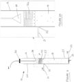
- a froth layer 32 which develops immediately above an interface located at the raised dynamic water level 37 (DWL, or H) of water which is located within the chamber 18.
- the static water level 34 rises to the dynamic water level 37 (or H) once the flow of air is added during the treatment process.
- the dynamic water level 37 can be controlled by various means, including by the design of the chamber and outlet, however the primary control is undertaken by variations in the inlet gas delivery rate, or water inflow and outflow rates.
- the inlet gas delivery rate can be regulated using information from a water level interface sensor which is located within the chamber 18, where signals from such a level sensor can be sent to a control system connected to an adjustable valve on the gas delivery line, or water inflow and outflow rates.
- the chamber outlet is arranged to allow water to egress from the chamber 18 nearer toward the lowermost in use end 25 of the flotation cell 10.
- the chamber outlet is in the form of a hole 36, arranged in the outer casing wall of the column 16, and into which a conduit 23 is located, and oriented orthogonally to the elongate axis of the column 16.
- the conduit 23 is arranged to permit the flow of liquid therethrough in use.
- the froth layer 32 formed above interface with the dynamic water level 37 in the chamber 18 will rise up inside the column 16 and further into the uppermost end 24 thereof.
- the wettest portion of the froth layer 32 is closest to the interface which forms at the upper surface of the dynamic water level 37 of water in the chamber 18, and it progressively drains and becomes drier as the froth layer 32 rises further above the interface within the column 16.
- Surface active material carried into the froth layer 32 includes the organic contaminant. In this way, the contaminant becomes much more concentrated in the froth layer 32 compared with its initial concentration in the feed water.
- the froth phase is also of considerably less volume to deal with for secondary processing, compared with the volume of feed water.
- a froth removal device is used to remove the froth layer 32 from the chamber 18.
- a froth removal device in the form of a suspended conical vacuum suction hood 38 is lowered to, and positioned at, an optimal distance above the dynamic water level 37 interface with the froth layer 32 in the well 14.
- the suction hood 38 is used to collapse the foamy froth concentrate and cause it to flow upward via a vacuum line 50 and into a liquid concentrate receiving container 51 as part of the pipe assembly 40 connected to a vacuum system operated by a pump 52.
- This system allows the collapsed froth to be further processed.
- the vacuum suction in the hood 38 is set to a minimum level sufficient to cause collapse of the drained froth layer 32 into a liquid form.
- the location of the vacuum suction hood 38 (acting as a froth depth regulation device) controls the amount of water in the froth layer 32, which therefore influences the concentration of the contaminant substance achieved in the froth layer 32.
- the inlet gas delivery rate into the chamber 18 can be regulated using information from a conductivity meter, or a water level sensor, which can be located at or below the vacuum suction hood 38, for example on an interior wall of the chamber 18. Signals from the water level sensor can provide information about the water content of the froth layer 32, and can be sent to a control system connected to an adjustable valve on the gas delivery line.
- a control system connected to an adjustable valve on the gas delivery line.
- the vacuum suction hood is arranged at a fixed location within the chamber 18, it is the location of the interface at the dynamic water level 37 which is responsive to changes in the flow of the introduced gas, and/or the water inflow and outflow rates.
- the aforementioned level sensors can inform a vertical positioning system 60 for the vacuum suction hood 38 to move it in an axial direction inside the column 16 to reach an appropriate position in relation to the interface at the dynamic water level 37.
- the positioning system may be a motor drive or some sort of mechanically actuated pulley system to adjust the height of the suction hood 38.
- the froth depth regulation device includes both the suction hood 38 and a movement guidance system in the form of a frame 62 which is attached to the suction hood 38 and is also fitted with one or more buoy floats 64 at its lowermost end which in use will cause the frame to float on the water in the chamber 18.
- These floats 64 mean that the frame 62 will always float at whatever is the vertical height of the interface 37 of water being treated in the column 16, and thus provides a fixed, optimal distance between the lower-facing, open mouth end 66 of the vacuum suction hood 38 and the interface 37.
- the suction hood 38 can maintain its vertical position relative to that froth layer interface without the need for a sensor and level control system, or operator intervention.
- No discrete step of raising or lowering of the hood within the chamber 18 is required to move the vertical position of the hood 38 in relation to the froth interface 37 (as is the case for the example 38 of Figure 3 ), and no changing of the gas flow rate is required to move the vertical position of the froth interface 37 in relation to a vacuum hood 38 (as is the case for the example of Figure 1 with a fixed vertical position suction hood in the chamber 18).
- the movement guidance system for the suction hood 38 shown in Figure 2 includes three vertically axially aligned and elongate T-bar shaped tracks 70 which are fitted to the interior wall of the chamber 18. Respective groove portions 68 of the frame are arranged to receive a respective one of these T-bar tracks, and to slide freely therealong in a tongue in groove style arrangement. In turn the suction hood 38 is operatively connected to said frame by means of the exit conduit 72.
- the flotation cell 10 can be used to remove a substance such as an organic contaminant from the water being treated.
- the present disclosure is mainly concerned with the removal of an organic substance known generally as a perfluoroalkyl substance or a polyfluoroalkyl substance (PFAS).
- PFAS polyfluoroalkyl substance
- This can include one or more of the group comprising: perfluorooctane sulfonate (PFOS); perfluorooctanoic acid (PFOA); perfluoro-n-hexane sulfonic acid, (PFHxS); poly fluorinated carboxylic acids, alkyl sulfonates and alkyl sulfonamido compounds; and fluorotelemeric compounds, each having differing carbon chain lengths; and including precursors of these.
- PFOS perfluorooctane sulfonate
- PFOA perfluorooctanoic acid
- PHxS perfluoro-n-hexane sulfonic acid
- fluorotelemeric compounds each having differing carbon chain lengths; and including precursors of these.
- the main substances of interest from this group are PFOS, PFHxS and PFOA which can persist in water for a long time.
- the bubbles rise upward over length of the chamber 18 and accumulate in the froth layer 32 located above the interface which forms at the upper surface of the dynamic water level 37.
- the collapsed froth concentrate containing the organic contaminant(s) When the collapsed froth concentrate containing the organic contaminant(s) has been discharged into a separate liquid concentrate receiving container, or knock-out vessel, it is then passed for secondary treatment involving either further concentration, destruction or removal of the contaminant.
- a final concentrate liquid is treated for removal of the concentrated organic contaminant(s), for example by absorption onto solid or semi-solid substrates (using activated carbon, clay, ion exchange resins or other organic materials), or by filtration (using reverse osmosis membranes to filter and increase the concentration of contaminant(s) and reduce treatment volumes). Once the absorption capacity of a substrate is exceeded it can then be regenerated or destroyed.
- Another option for secondary treatment is the further concentration of the collapsed froth may be undertaken using a similar process to that used for the initial separation step and may be conducted in above ground treatment apparatus where the collapsed froth is subject to further gas sparging and froth concentration. Multiple concentration steps may be undertaken using this approach to minimise the volume of fluids requiring treatment. Residual fluids produced during the concentration steps may be re-introduced to the start of the process or, where appropriate, released to a liquid waste disposal/treatment system or to the environment. This will now be described in more detail with reference to the system shown in Figure 4 .
- Figure 4 illustrates a series of foam fractionation columns 16, to support rapid foam generation via aeration of the water that is being treated in the columns 16.
- the system shown can operate using continuous flow or as a batch process depending on the concentration and nature of PFAS contaminants and co-contaminants.
- the column In a batch application the column is filled to a predetermined level and this batch is treated within the confines of the column for a fixed period before it is released to the next stage of the fractionation process. Typically this approach is used where longer retention times are required.
- the diffuser/sparger is designed to create a tailored spectrum of optimally sized bubbles, which rise up through the water within the column 16.
- the dense bubble stream which is produced, and the high interfacial surface area of the bubbles provides both sufficient mixing agitation as well as a strong attraction for PFAS which may be present in solution in the feed water.
- the PFAS molecules are quickly scavenged from the water and drawn to the top of the water column.
- the foam formed at the top of water column is highly enriched in PFAS and by using the vacuum extraction head, the foam can be crowded and drained. Before the foam has a chance to collapse and dissolve back into the water, it is harvested by the vacuum extraction head and drawn into a centralised collection tank.
- the water travelling through the column (now depleted in PFAS) is discharged through the outlet conduti near the column base and then into a secondary fractionation column for further treatment.
- Fractionated residual water flowing from the secondary treatment column is directed to a temporary holding tank and, only after further assessment and confirmation of compliance with regulatory guidelines, are they redirected back to a liquid waste disposal/treatment system or released to the environment.
- PFAS concentrate/foam drawn from the primary 16 and secondary 16A fractionation columns is temporarily stored in a "knock-out" vessel 51.
- This material is then further processed in a third fractionation column 16B especially designed for concentrates to create a hyperconcentrate. Hyperconcentrate/foam removed from the the third fractionation column 16B is directed for storage and then finally for offsite destruction.
- Treated water flowing in conduit 76 from the base of the concentrate fractionation column 16B is returned to the primary feed tank 74 for reprocessing or where appropriate redirected to a liquid waste disposal/treatment system or released to the environment. Vacuum exhaust air from all fractionation columns are directed through absorptive filters prior to release to atmosphere.
- PFOS and PHFxS both of the key priority PFAS compounds of concern
- PFOS and PHFxS can be successfully removed by Foam Fractionation (FF).
- FF Foam Fractionation
- PFHPA Perfluoroheptanoic Acid
- FF Perfluoroheptanoic Acid
- the three other secondary priority compounds (PFHxA, PFBS and PFPeS) were shown to be minimally, or not affected by FF, and thus can be separated from the primary priority compounds using the foam separation which has been developed.
- FF is ideally suited to physically removing the priority PFAS molecules (including other theoretical non-PFAS co-contaminates) allowing more sophisticated (and expensive) techniques to be reserved as polishing treatments to achieve concentrations below criteria for regulated disposal or discharge.
- the inventors collected 960L of impacted groundwater from Site 1 and 40L of water stored in an above-ground tank located at Site 2. These waters were eventually combined in one IBC and approximately 550L of the resulting mix was put through a fractionation column to create a concentrate. This concentrate was then put through a secondary fractionation column to create a hyper-concentrate. The start and end concentrations of fractionate are shown in the table and graph below: Treatment Time (min) PFAS Concentration (ug/L) PFHxS PFOS PFOA 0 2000 8400 700 3 1900 6400 680 10 1700 2300 640 15 1500 250 480 25 130 1.7 1.9 32 1.1 0.6 0.1
- Priority PFAS Compound Removal The study data shows that the priority compounds can be treated to near or below recreational guidelines from highly contaminated source concentrates. Drinking water targets of 0.07ugAL will be achievable by extending detention times within the column or by redirecting fluids through an alternative "polishing" process.
- the inventors were engaged to design, supply, construct, commission and operate a water treatment plant (WTP) for the removal of PFAS from impacted groundwater at an aviation base site.
- WTP water treatment plant
- the climatic conditions used for the project are based on weather data from the Bureau of Meteorology. Temperature and rainfall statistics are taken from the nearest weather stations to the site. Table 1: General Site conditions Condition Value Units Highest Maximum Temperature 42.8 0 C Lowest M inimum Temperature -7.5 0 C Mean Max imum Temperature 31.0 0 C Mean Minimum Temperature 2.9 0 C HighestRecorded Daily Rainfall 130.0 mm Maxi mum Wind Gust Speed 161 km/h Mean Wind Speed 18.6 km/h
- Table 2 The basis of design for the WTP is identified in Table 2 below: - Table 2: Design Parameters Condition Value Units Groundwater Treatment Volume (contractual requirement) 1.5 ML/week WTP Design Treatment Volume 250 kL/day Number of grouddwater Extraction Wells Developed Concept Well Field Design) Up to 20 ea Design Extraction Rate 2.9 L/s Distance from Extraction Wells to WTP ⁇ 650 m Extraction Pump Design Specification - Flow Rate for Developed Concept Well Field Design 0.14 to 0.2 @ 20 L/s mbgs Number of Treated Water Reinjection Wells Up to 8 ea Design Reinjection / Dispersion Rate 2.9 L/s Distance from WTP to Reinjection Wells ⁇ 430 m Contractual Qty Up to 150m above ground poly pipeline.
- the WTP will require 24/7 operation capability, excluding scheduled and reactive maintenance, with manned periods Monday to Saturday during the day.
- the system has been designed with consideration of the following criteria: -
- FIG. 5 illustrates the WTP System Schematic / Process Flow Diagram that identifies all stages from groundwater extraction (Stage 1) through to treated water return / reinjection (Stage 16). Each stage will now be described.
- the WTP process flow diagram has been developed in a manner that the stages are independent of each other to ensure performance of each stage is optimal. Where possible, each stage has its own storage / feed tank that allows level control to provide over fill protection from the previous stage and also pump protection for the current stage. This also allows pumps to operate at their specified design parameters utilising simple level control for on/off operation.
- the WTP process flow control diagram for the system is shown in Figure 6 .
- Stage 1 scope of work includes supply, installation, commissioning and operation of the groundwater well pumps and pipeline from the groundwater well location to the WTP.
- the well field design includes up to 20 extraction wells that require approximately 650m of pipeline; and up to 8 reinjection wells that require approximately 430m of pipeline from the WTP location.
- the extraction wells have been categorised as high, medium and low priority based on their expected yields and PFAS concentration levels. There are 9 high priority, 7 medium priority and 4 low priority extraction wells, all of which are located within very densely populated underground service areas and with 6 of the extraction wells located in areas that are at risk of drawing hydrocarbon contamination from a light non-aqueous phase liquid plume.
- the reinjection wells have been categorised with 4 high priority, 2 medium priority and 2 low priority wells.
- the principal behind categorising the well network is to develop the high priority wells first and test their yield characteristics immediately following drilling to ascertain whether the lower priority wells require development and to potentially save costs to the project.
- the WTP has been designed to process 250kL per day, which will meet the contractual volume of 1.5ML/week.
- the 250kL per day process requirement is equivalent to 174 L/min or 2.9 L/s if operated on a 24/7 basis.
- All pipework between the groundwater well manifold point and the WTP will be buried HDPE pipe.
- Current sizing and specification will be Pressure Pipe to AS/NZS 4130, DN63 SDR11 PN16 PE 100 (black with blue stripe) which will experience a flow velocity of approximately 1.5 m/s under full flow of 2.9 L/s and is rated to 1,600 kPa at 20°C.
- a common trench will be utilised for the water pipe, electrical conduits/cabling and communications/control cabling.
- Stage 2 of the WTP is identified as pre-process storage and solid settling.
- the primary purpose of this stage is to allow settling of suspended solids from the extracted groundwater prior to the WTP process.
- a 16kL sloping bottom tank has been selected to allow the suspended solids sludge to be removed from a low point drain without having to empty the tank, or halt the process and enter the tank.
- the treatment water outlet of this tank will be set well above the tank bottom to ensure any settled solids are not disturbed or mixed during delivery to the following stages. Sludge waste from this tank will be removed, dried and disposed of.
- a sampling point (SP2-01) has been included in Stage 2 to allow analysis of the incoming ground water before any processing by the WTP.
- This stage also includes a flowmeter that will be used to measure and record total source water flow rates and cumulative flow volumes.
- Stage 3 of the WTP is identified as hydrocarbon separation and removal. Hydrocarbons are frequently found in groundwater at a military air base and can have a deleterious effect on downstream processes such as foam flotation as well as contaminating ion exchange resins.
- This stage includes a Baldwin Oily Water Separator (OWS) or coalescing plate separator (CPS).
- the Baldwin Oily Water Separator removes any free phase hydrocarbons from the groundwater based on Stokes' Law which is the physical law governing the settling/rise rate of a particle/droplet in a fluid stream.
- the groundwater is drawn from the tank through a non-emulsifying diaphragm pump to the above ground coalescing plate separator.
- the CPS is designed to remove non-dissolved hydrocarbons and suspended solids to a level suitable for discharge to stormwater.
- the water passes through the coalescing plates and then through a polishing chamber before being stored in a discharge chamber. There will be three waste streams from the CPS.
- Solid waste will be collected from the low point drain under the coalescing plate of the CPS. Free phase hydrocarbons will be separated into a collection tank within the CPS and drained from the low point drain. The fabric based polishing filters will be replaced on an 'as required' basis when they become saturated with hydrocarbons. All waste will be removed, dried (where appropriate) and disposed of.
- Stage 4 includes a 10kL storage tank for the purposes of aeration prior to stage 5.
- Fe the main analyte of concern
- a mechanical process was decided to be most practical.
- a mechanical process using venturis or diffusers only adds air and dissolved oxygen to the groundwater and removes the requirement for hazardous chemical storage, handling and treatment, and is also less likely to have broader effects on the groundwater composition.
- Oxidation will be achieved by utilising a high flow pump connected to several venturis, which will introduce air bubbles and oxygen into the water. The introduced air will facilitate the oxidation of the dissolved Iron (Fe) and Manganese (Mn) whose oxides will precipitate from solution to allow filtration removal in Stage 6. Removing these ions depends on the groundwater at the site and the extent of the downstream effects on the foam fractionation stages.
- the tank has been sized to 10kL and will be fitted with a single pump with 2 x 50mm venturis providing adequate aeration for the volume. This tank will also provide additional storage equivalent to 1 hour of full flow WTP operation to reduce the dependency of the WTP on the Oily Water Separator or filtration maintenance.
- the Stage 4 tank will include high and low level sensors for the control of the Stage 3 Oily Water Separator pump operation and also to provide pump protection of the following stage pump respectively.
- a sampling point (SP4-01) has been included in Stage 4 to allow analysis of the Oily Water Separator treatment prior to the oxidation plug flow reactor.
- Stage 5 of the WTP is identified as an oxidation plug flow reactor and allows the aerated water from stage 5 to extend the dwell time for oxidation and precipitation of Fe and Mn.
- the process is a simple mechanical method of extending the water path whilst maintaining the same plug or volume of water, allowing the reaction with the dissolved oxygen for a longer period of time.
- the plug flow reactor will be fabricated from coils of polyethylene pipe that will produce an 800m long route for the water to pass. The water will be subject to elevated temperature from the black polyethylene pipe, which will further aid the oxidation process.
- Stage 6 includes a series of bag filters for the removal of fine suspended solid particulates.
- the first stage of filtration will utilise 5-micron filter bags to remove larger particulates.
- the second stage will utilise two 1-micron absolute filters in parallel to maintain the required flowrate. Pressure differential alarms have been included across all filters to monitor filter media levels and alarm through the PLC prior to pump shut down.
- Waste collected in the filters will be removed, dried and disposed of.
- a sampling point (SP7-01) has been included after Stage 6 to allow analysis of the treated water following that stage.
- the staged process adopted involves initially filling the vessel to a starting height which is established to ensure that not too much water/foam is ejected through the hood during start-up aeration.
- the operator introduces a low flow overflow feed of the same original source water into the main tank which causes the minimal residual PFAS gathering at the water surface to overflow out the top of the conical chimney / clear cap which is located at the top of the lid of each tank.
- This upper tank cap allows a visual inspection of what is taking place inside the tanks, allows an operator to study the condition of the froth, and also gives a quick visual indication of water level.
- FIGS 7 , 7A , 8 , 8A and 8B are drawings of the SAFF fractionation vessel which shows the rings of water and air piping manifolds, which service the venturis which are located at the base of the tank and also the hood. These SAFF units are effectively operating in batch mode, to extract the maximum recovery of PFAS into the foam concentrates.
- the PFAS rich foam/liquid concentrate generated from the top of the five fractionation vessels will be directed to a 5kL storage tank in Stage 8 where it will be collected for filling of the hyper concentrate fractionation vessel.
- Table 7 illustrates the expected reduction in water volume and associated increase in concentration of PFAS levels throughout the WTP process.
- Treated water drained from the Stage 7 fractionation vessels (representing approximately 95% of the total inflow) will be pumped to the resin treatment stages of the WTP with an estimated PFAS concentration of less than 1 ⁇ g/L.
- the PFAS enriched concentrate from the Stage 7 fractionators (representing approximately 5% of the total inflow) will be directed to the hyper-concentration unit in Stage 8.
- a sampling point (SP8-01) has been included at the storage tank (T8-01) following the Stage 7 SAFF vessels to allow analysis of the PFAS concentrated waste water prior to hyper-concentration.
- a sampling point (SP12-01) has been included at the storage tank (T12-01) at stage 12 to allow analysis of the treated water following fractionation and prior to resin treatment.
- Stage 8 of the WTP consists of a 5kL PFAS concentrate storage tank (T8-01) and hyper-concentrate fractionation vessel.
- the hyper-concentrator will operate independently of the Stage 7 fractionation vessels and can be turned on and off as needed as it works on a much smaller volume of PFAS affected water.
- the hyper-concentrator will utilise a similar method to that of the Stage 7 fractionation vessels with the addition of PFAS rich foam extraction under vacuum and sent to the next stage knock-out drum.
- the treated water from the hyper-concentrator vessel will be returned to the Stage 7 storage tank for reprocessing.
- Vacuum suction foam extraction system is featured in the top of the hyper-concentrator vessel.
- This vessel will take the foam and overflow water produced from the primary vessels and refractionate this fluid using a staged approach.
- a low flow top-up feed is introduced to raise the water level in the vessel so that it sits just below ( ⁇ 50mm) below a vacuum extraction device.
- a flat plate is used as the suction hood device, which is fixed within the narrower neck at the top of the hood section of the foam fractionation tank.
- the top up feed continues to operate during the (approximately 25minute) fractionation process, but is regulated using a high/low float level detection system to ensure that the vacuum plate stays at an optimal distance from the water surface/meniscus/interface with the foam.
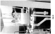
- the swirl action is also being adopted in the hyper-concentrator as it seems to also reduce turbulence in the upper water interface and, as a consequence, produces a dryer foamate (see Figure 9 ).
- Stage 9 of the WTP is identified as a knock-out drum.
- the hyper-concentrated PFAS foamate extracted from the hood of the hyper-concentrate vessel is drawn into the knock-out drum under vacuum.
- the hyper-concentrate liquid is then pumped to the vacuum distillation system for further volume reduction.
- the vacuum distillation system is a low energy vacuum distillation process which boils the water content from the waste stream off under vacuum at around 37°C.
- the principle of the vacuum distillation phase is that all substances having higher boiling points than water stay in the evaporation residue. This includes heavy metals, salts as well as oils and fats.
- PFOS has a boiling point of 259 °C and PFOA boils at 192.4 °C.
- the evaporation residue i.e. the PFAS hyper-concentrate
- the emerging vapour is practically free of impurities. As this clean steam passes through the distillation columns within the evaporator it is cooled back to a pure liquid.
- a sampling point (SP10-01) has been included at the storage tank (T10-01) to allow analysis of the distilled water following that vacuum distillation process.
- Distilled water from the vacuum evaporator will be transferred to the storage tank (T7-01) for re-processing.
- the volume of distilled water produced on a daily basis is expected to be in the order of 300 litres per day.
- a sampling point (SP10-01) has been included at the storage tank (T11-01) to allow analysis of the distilled water produced by the vacuum distillation process.
- Stage 11 represents the last of the waste minimisation processes and aims to further reduce the moisture content in the liquid from the distillation unit.
- the liquids will be pumped into a 200L disposal drum encapsulated within the drum dryer which heats from the outside of the drum. Since the heating elements do not contact the liquid, there is no requirement to clean the heat transfer surface. Temperatures are controlled with a thermocouple and timer system to provide consistent heating and accurate level of dryness. Hi torque motor with reduction gearing provide a gentle and consistent agitation process, even as solutions become more viscous and solid.
- a pneumatic lifting system allows easy removal of lid and agitator system at the completion of this drying phase. Hinged clamshell walls along with pneumatic lifting system allow easy removal of drum and dolly for loading and unloading.
- the inventors will install a Duty-Standby system containing an ion exchange hydrocarbon "scavenging" resin.
- the frequency of scavenging resin replacement is yet to be determined and will depend on the concentration and type of hydrocarbon exposure. Expired resins will be removed, dried and disposed of.
- Stage 13 of the WTP is identified as PFAS polishing resin and is used to remove any residual PFAS in the treated water.
- the PFAS absorbent polishing resin is a critical part of the process and as such, it was decided to expand the infrastructure from what was offered in the DCAP to include three resin vessels in a "Lead-Lag-Standby" configuration.
- Pipework has been designed to allow a carousel style operation where Vessel A will start as the Lead, Vessel B as the Lag in series and Vessel C as the Standby.
- the Lead vessel will be subject to the initial flow and as such, will do the most work and be depleted or fouled first.
- the pipework will be reconfigured so that Vessel B becomes the Lead, Vessel C the Lag and Vessel A the Standby. Whilst a vessel is in standby mode, it will be backwashed. Expired resins will be removed, dried and disposed of.
- Stage 14 incorporates a treated water backwash to remove foulants, followed by a brine soak to minimise biofouling.
- a supply storage tank (T14-01) is utilised to generate and mix the brine solution.
- the Lead vessel will be taken offline and subject to a back wash from the treated water tank (T14-02).
- the treated backwash water will be circulated through a filter (F14-01) to remove any foulants before being returned to its storage tank.
- the vessel On completion of the backwash process, the vessel will be filled with brine water to inhibit formation of bio-foulants during the Standby period.
- Stage 15 of the WTP is identified as outflow storage. This stage consists of five 10,000L tanks in a manifolded system to allow individual tank storage and discharge in 10,000L batches, or combined storage and discharge of 50,000L. During the commissioning phase, the tanks will be utilised in the individual configuration, allowing treatment, testing and storage on up to five consecutive days before discharging the treated water to reinjection if acceptable or returning the treated water to the WTP if unacceptable. Once the commissioning phase is complete and the WTP is proven under "Normal Operation", the outflow storage will be manifolded as one large storage vessel prior to reinjection.
- Stage 15 also includes a flowmeter that will be used to measure and record return treated water flow rates and cumulative flow volumes.
- Stage 16 of the WTP is identified as the treated groundwater return or reuse. There are alternate options for treated groundwater reuse or reinjection. In regard to reinjection, the WTP has 8 reinjection wells that have been classified as 4 high priority, 2 medium priority and 2 low priority.
- Inventors have allowed to install 150m of above ground poly pipe between the WTP and the reinjection points to allow the gravity feed of water to the wells.
- the WTP has been designed to minimise the production of waste. Wherever possible, mechanical means have been employed to extract and concentrate wastes to minimise management and disposal costs.
- the following table summarises the waste produced and method of disposal proposed for each relevant stage of the WTP.
- Stage Waste Type Approx. Volume / Mass Management Disposal Method 2,3 Sediment and solid particulates Unknown. Dependent on well performance. We have installed a sloping bottom tank to allow removal of solids. Reduced via Stage 11 (Drum Dryer) and disposed of. 3 Liquid Hydrocarbons and polishing filters Unknown. Dependent on groundwater source. Liquid hydrocarbons drained from OWS into container. Polishing filters removed and replaced Reduced via Stage 11 (Drum Dryer) and disposed of.
- Table 7 indicates the design waste volume reduction and PFAS concentrate levels expected through the WTP process. These figures are based on the daily treatment volume of 250kL.
- Table 3 Waste Volume Reduction and PFAS Concentrate Levels Stage Description Volume In - L/day (PFAS Level) Volume Processed - L/day (PFAS Level) Concentrate / Waste - L/day (PFAS Level) Reduced Volume - % Operating Time - Hrs/day 7 First stage (5 x vessels) 250,000 (30 ⁇ g/L) 225,000 ( ⁇ 1 ⁇ g/L) 12,500 (581 ⁇ g/L) 5% 24 8 Hyper-concentrator 12,500 (581 ⁇ g/L) 12,187.5 ( ⁇ 2 ⁇ g/L) Returned to Stage 7 above 312.5 (23,162 ⁇ g/L) 2.5% 8 10 Knock Out Drum 250 250 100% 4 10 Vacuum Distillation 312.5 (23,162 ⁇ g/L) 296.9 (42 ⁇ g/L) Returned to Stage 7 above 15.6 (600,000
- Figure 10 illustrates the expected reduction in volume and increase in PFAS concentration through the various stages of the WTP based on testing carried out in the laboratory.
- the stages within the WTP have been grouped as follows: -
- the SAFF process is fundamental in bulk water treatment to significantly reduce the PFAS level, resulting in approximately 99% of the groundwater being reduced to a PFAS level of approximately 1 ⁇ g/L and less than 1% of the initial volume concentrated up by a factor of 200 times the original PFAS levels.
- the next stage of vacuum distillation and drying further reduces the volume of the SAFF waste stream from 1,250 L at approximately 6,000 ⁇ g/L down to 2.5L at approximately 3,000,000 ⁇ g/L, which equates to further concentration factor of 500 times.
- the SAFF treated water is then passed through the PFAS polishing resins, reducing the level from approximately 1 ⁇ g/L to levels that satisfy the contractual requirement.
- the WTP benefits from the SAFF process managing the maj ority of PFAS removal / reduction to ensure that the PFAS polishing resin can work effectively and efficiently, whilst minimising the waste generated.
- the WTP has been designed to fit on an overall footprint of 35m x 25m that will be fenced and secured from general access.
- the design also includes a bunded area of 25m x 15m, where all PFAS containing equipment will be housed. Asphalt was considered for bund material of construction however concrete has been selected as it will handle the elevated temperatures without distortion and is more resilient to forklift and crane traffic. Concrete is also subject to PFAS absorption and the bund surface will be sealed / painted to reduce this risk.
- a road-base style hardstand will be laid in the footprint of the WTP to raise the level of the complete WTP site.
- the concrete bund will then be constructed on top of the hard stand to further increase the elevation from normal ground level and to ensure no ingress of pooled water during rain events.
- the surface of the bund will have a fall to a low point sump that will allow first flush retention and processing through the WTP.
- the sump will be located in the vicinity of the Stage 2 storage tanks to allow easy transfer of rain water to the WTP in the first instance and then diverted to the surrounding surface water drainage system following the first flush. Sump level control will be utilised to establish a suitable volume for first flush.
- Figures 11 and Figure 12 illustrate the WTP layout based on the current design and process flow.
- the WTP will be operated from a central PLC that will be used to manage, record as necessary and report operations from Stage 1 through Stage 16.
- the system has been designed to ensure independence between stages to simplify the control process and produce a robust fit for purpose design.
- Many of the stages will utilise a similar and simple logic for operations of that stage as identified below:
- the WTP will be constructed and operated on a bunded footprint that will have the capacity to retain the largest combined vessel volume of 50,000L plus 5%, resulting in a bund height of ⁇ 120mm based on a footprint of 25m x 15m.
- the containers will also be bunded to ensure any potential leak from the process is initially contained within the container. Sensors will be implemented in the container bunds to alarm if any leak occurs, noting that the plant will operate 24/7 but only be manned for 5-1/2 days per week.
- the control process will alarm when a limit is reached and then will stop operations when the second set point is reached.
- the alarm process will also send a message to the operator to allow review or mobilisation to site if not on site.
- Surveillance cameras may be introduced for operational monitoring and to allow remote inspection for any alarm notification.
- the facility has been designed with a layout that supports the process flow and also minimises access to areas that do not require attention.
- Container access will be provided to allow ease of construction, inspection and maintenance. Accessibility has been considered for forklift / trolley access to plant that requires media changeout or manual handling.
- the stages that contain the higher concentrates of PFAS have been grouped and will be segregated from other working areas where practicable.
- E-Stop system will be implemented to allow immediate shutdown of operations.
- the E-Stops will be located within easy access of general work areas within the facility and an emergency eye wash/shower station has been included in the vicinity of the higher concentrated PFAS areas as indicated in the WTP layout above.
- froth and “foam” may be used interchangeably but are taken to mean the same thing, essentially comprising a wet liquid concentrate having low quantities of particulate materials or concentrated organic contaminants, and extracted by various designs of devices which aim to provide as much control and reduction of the water content in the froth layer as possible.
Landscapes
- Engineering & Computer Science (AREA)
- Life Sciences & Earth Sciences (AREA)
- Chemical & Material Sciences (AREA)
- Hydrology & Water Resources (AREA)
- Environmental & Geological Engineering (AREA)
- Water Supply & Treatment (AREA)
- Organic Chemistry (AREA)
- Biotechnology (AREA)
- General Engineering & Computer Science (AREA)
- Dispersion Chemistry (AREA)
- Physical Water Treatments (AREA)
Claims (10)
- Procédé de séparation d'une quantité d'une substance organique à partir d'eau qui est contaminée par la substance organique, ladite substance organique étant au moins une substance perfluoroalkyle ou une substance polyfluoroalkyle (PFAS), le procédé comprenant les étapes suivantes :- l'admission de ladite eau contaminée dans une chambre (18) via une entrée (22) dans celle-ci ;- l'introduction d'un flux de gaz dans une région la plus basse (25) de la chambre (18), dans lequel le gaz introduit induit un flux d'eau vers le haut dans la chambre (18) et produit une couche de mousse (32) qui s'élève au-dessus d'une interface (37) avec l'eau dans une partie supérieure (24) de la chambre (18), la couche de mousse (32) comportant une quantité concentrée de la substance par rapport à sa concentration dans l'eau contaminée admise en premier dans la chambre (18) ;- la collecte d'une quantité suffisante de ladite couche de mousse (32) et, après l'avoir laissée s'affaisser sous une forme liquide, le passage dudit liquide vers une seconde chambre via une entrée dans celle-ci ;- l'introduction d'un flux de gaz dans une région la plus basse de la seconde chambre, dans lequel le gaz introduit induit un flux d'eau vers le haut dans ladite chambre, et produit une couche de mousse qui s'élève au-dessus d'une interface avec l'eau dans une partie supérieure de la seconde chambre, la couche de mousse comportant une quantité encore plus concentrée de la substance ; et dans lequel- dans ladite seconde chambre, la régulation :(i) de la profondeur de la couche de mousse au-dessus de l'interface, en contrôlant un paramètre physique de la couche de mousse à l'aide d'un dispositif de régulation de profondeur de couche de mousse (38) pour maintenir une profondeur de couche de mousse au-dessus de l'interface, le dispositif étant agencé pour pouvoir être positionné de manière mobile dans la chambre (18) en réponse au mouvement de l'emplacement de l'interface ou au niveau d'un emplacement fixe dans la chambre (18), et l'emplacement de l'interface réagit à au moins l'un du flux du gaz introduit et d'un flux d'entrée de l'eau, et(ii) de la profondeur de l'eau dans la chambre, par au moins l'un des moyens du groupe comprenant : le contrôle d'un paramètre physique du flux de gaz introduit ; et le contrôle d'un flux d'entrée d'eau supplémentaire ;ladite régulation étant en réponse au mouvement de l'emplacement de l'interface (37) de sorte que la teneur en eau de la couche de mousse (32) près de la région la plus haute de la seconde chambre est contrôlée, pour influencer la concentration de la substance dans celle-ci,et dans lequel pour au moins l'une des première ou seconde chambres, le flux de gaz vers le haut et la production de la couche de mousse se produisent de manière opérationnelle par lots.
- Procédé selon la revendication 1, dans lequel l'étape de contrôle d'un paramètre physique du flux de gaz introduit comprend l'utilisation d'un régulateur de flux et d'une vanne d'admission pour contrôler le flux dudit gaz introduit dans la chambre.
- Procédé selon l'une quelconque des revendications précédentes, dans lequel l'étape de contrôle d'un paramètre physique du flux de gaz introduit comprend l'utilisation d'un ou de plusieurs tuyaux de flux d'entrée de gaz qui sont agencés pour s'étendre dans l'intérieur de la chambre et conçus pour induire un flux généralement rotatif ou tourbillonnant dudit gaz introduit et de l'eau, ledit flux tourbillonnant ayant un axe de rotation aligné avec un axe allongé de la chambre.
- Procédé selon la revendication 3,
dans lequel le flux généralement rotatif ou tourbillonnant dudit gaz introduit et de l'eau à l'intérieur de la chambre est laminaire au niveau de la paroi circonférentielle intérieure de la chambre. - Procédé selon l'une quelconque des revendications précédentes, dans lequel l'étape de contrôle d'un paramètre physique du flux de gaz introduit comprend l'utilisation d'un dispositif de génération de bulles situé avant ou au moment où ledit gaz introduit pénètre dans l'eau située dans la chambre.
- Procédé selon l'une quelconque des revendications précédentes, dans lequel l'étape de contrôle d'un paramètre physique de la couche de mousse comprend en outre l'utilisation d'un dispositif pour confiner le trajet de flux transversal de la mousse dans la partie supérieure (24) de la chambre (18), ce qui entraîne le drainage de ladite couche de mousse.
- Procédé selon la revendication 6, dans lequel la couche de mousse est affaissée pendant ladite étape de retrait de la partie supérieure de la chambre, et avant de subir une étape de traitement secondaire.
- Procédé selon la revendication 7, dans lequel la couche de mousse est affaissée à l'aide d'un appareil mécanique du groupe comprenant : un briseur de mousse, un dispositif d'extraction sous vide (38) et une tête d'extraction de mousse.
- Procédé selon la revendication 7 ou la revendication 8, dans lequel l'étape de traitement secondaire pour traiter la couche de mousse affaissée comportant la substance concentrée utilise au moins l'un des processus du groupe comprenant : l'absorption telle que l'utilisation de charbon actif, d'argile ou de résines échangeuses d'ions, la filtration telle que l'utilisation de membranes d'osmose inverse ; et
l'introduction d'une quantité supplémentaire de gaz dans un appareil de confinement séparé pour produire une autre couche de mousse comprenant une quantité supplémentaire concentrée de la substance. - Procédé selon l'une quelconque des revendications précédentes, dans lequel la substance perfluoroalkyle ou polyfluoroalkyle (PFAS) comporte un ou plusieurs éléments du groupe comprenant : le sulfonate de perfluorooctane (PFOS) ; l'acide perfluorooctanoïque (PFOA) ; l'acide perfluoro-n-hexanesulfonique (PFHxS) ; l'acide perfluorononanoïque (PFNA) ; l'acide perfluorodécanoïque (PFDA/Ndfda) ; les composés sulfonate de fluorotélomère 6:2 (6:2 FTS) ; les composés sulfonate de fluorotélomère 8:2 (8:2 FTS) ; et l'acide perfluorooctanoïque (PFHpA) ; les acides carboxyliques polyfluorés, les alkylsulfonates et composés alkylsulfonamido ; et les composés fluorotélémériques, chacun ayant des longueurs de chaîne carbonée différentes ; et comportant des précurseurs de ceux-ci.
Priority Applications (1)
| Application Number | Priority Date | Filing Date | Title |
|---|---|---|---|
| EP25171263.4A EP4631624A1 (fr) | 2017-12-09 | 2018-12-10 | Procédé et appareil pour la séparation d'une substance de l'eau |
Applications Claiming Priority (3)
| Application Number | Priority Date | Filing Date | Title |
|---|---|---|---|
| AU2017904954A AU2017904954A0 (en) | 2017-12-09 | Method and apparatus for separation of a substance from water | |
| AU2018904046A AU2018904046A0 (en) | 2018-10-25 | Method and apparatus for separation of a substance from water | |
| PCT/IB2018/059830 WO2019111238A1 (fr) | 2017-12-09 | 2018-12-10 | Procédé et appareil de séparation d'une substance de l'eau |
Related Child Applications (1)
| Application Number | Title | Priority Date | Filing Date |
|---|---|---|---|
| EP25171263.4A Division EP4631624A1 (fr) | 2017-12-09 | 2018-12-10 | Procédé et appareil pour la séparation d'une substance de l'eau |
Publications (4)
| Publication Number | Publication Date |
|---|---|
| EP3720610A1 EP3720610A1 (fr) | 2020-10-14 |
| EP3720610A4 EP3720610A4 (fr) | 2021-08-11 |
| EP3720610C0 EP3720610C0 (fr) | 2025-04-23 |
| EP3720610B1 true EP3720610B1 (fr) | 2025-04-23 |
Family
ID=66751373
Family Applications (2)
| Application Number | Title | Priority Date | Filing Date |
|---|---|---|---|
| EP18886120.7A Active EP3720610B1 (fr) | 2017-12-09 | 2018-12-10 | Procédé de séparation d'une substance de l'eau |
| EP25171263.4A Pending EP4631624A1 (fr) | 2017-12-09 | 2018-12-10 | Procédé et appareil pour la séparation d'une substance de l'eau |
Family Applications After (1)
| Application Number | Title | Priority Date | Filing Date |
|---|---|---|---|
| EP25171263.4A Pending EP4631624A1 (fr) | 2017-12-09 | 2018-12-10 | Procédé et appareil pour la séparation d'une substance de l'eau |
Country Status (7)
| Country | Link |
|---|---|
| US (2) | US12139420B2 (fr) |
| EP (2) | EP3720610B1 (fr) |
| CN (2) | CN112004607B (fr) |
| AU (2) | AU2018378556B2 (fr) |
| CA (1) | CA3085281A1 (fr) |
| ES (1) | ES3029752T3 (fr) |
| WO (1) | WO2019111238A1 (fr) |
Families Citing this family (37)
| Publication number | Priority date | Publication date | Assignee | Title |
|---|---|---|---|---|
| US11413668B2 (en) | 2018-10-04 | 2022-08-16 | Ezraterra, Llc | Sintered wave multi-media polarity conversion treatment apparatus and process for nondestructive removal and condensation of per- and polyfluoroalkyl substances (PFAS) and other dangerous compounds |
| CN110342728A (zh) * | 2019-05-10 | 2019-10-18 | 江苏智诚达环保科技有限公司 | 一种微纳米气浮耦合电氧化装置去除废水中全氟化合物的方法 |
| SE543716C2 (en) * | 2019-05-17 | 2021-06-29 | Bjoerks Rostfria Ab | Apparatus, system and methods for water processing |
| IL291088B2 (en) | 2019-09-06 | 2025-10-01 | The Water & Carbon Group | Low energy water treatment |
| US12583767B2 (en) * | 2020-01-15 | 2026-03-24 | GSI Environmental, Inc. | Method and apparatus for removal of per- and polyfluoroalkyl substances (PFAS) from groundwater |
| EP4082303A4 (fr) * | 2020-01-28 | 2024-01-24 | Plasma Tech Holdings, LLC | Système pour la destruction d'une matière dangereuse |
| WO2021162914A1 (fr) * | 2020-02-12 | 2021-08-19 | Ezraterra, Llc | Appareil de traitement de conversion de polarité multisupport à ondes frittées et procédé d'élimination non destructive et de condensation de substances per-et polyfluoroalkyle (pfas) et d'autres composés dangereux |
| WO2021188493A1 (fr) * | 2020-03-16 | 2021-09-23 | University Of Florida Research Foundation | Traitement de substances per- et poly-fluoroalkyle dans lixiviat de décharge |
| KR20230048325A (ko) * | 2020-08-06 | 2023-04-11 | 바텔리 메모리얼 인스티튜트 | 역삼투법 및 염 분리법을 이용한 pfas의 염 분리 및 분해 |
| US12410071B1 (en) | 2020-10-19 | 2025-09-09 | Wm Intellectual Property Holdings, L.L.C. | System and method for removal of PFAS and other emerging contaminant micro-constituents from landfill leachate and other impacted liquids |
| EP4237381A4 (fr) | 2020-11-27 | 2024-09-18 | EGL Water Pty Ltd | Procédés et appareils de réduction de concentration de contamination par substances perfluoroalkylées dans les eaux usées et/ou le sol |
| CN112720932A (zh) * | 2020-12-02 | 2021-04-30 | 东北师范大学 | 一种微塑料分离回收装置及其使用方法 |
| EP4255853A4 (fr) * | 2020-12-03 | 2024-10-30 | Opec Remediation Technologies Pty Limited | Procédé de séparation |
| CN117242037A (zh) * | 2020-12-03 | 2023-12-15 | 欧佩克修复技术有限公司 | 分离方法 |
| US11667546B1 (en) * | 2020-12-09 | 2023-06-06 | The United States Of America, As Represented By The Secretary Of The Navy | Drop-in treatment apparatus and system for PFAS-impacted liquids |
| WO2022167958A1 (fr) * | 2021-02-02 | 2022-08-11 | OPEC Remediation Technologies Pty Ltd | Procédé et appareil pour séparer une substance de l'eau |
| US11484922B2 (en) | 2021-03-25 | 2022-11-01 | Ezraterra, Llc | Apparatus and methods for removal, measurement, and mapping of per- and polyfluoroalkyl substances |
| US20220363567A1 (en) * | 2021-05-14 | 2022-11-17 | Bonn Justin | Method to Remove and Concentrate PFAS from Water |
| US20230139452A1 (en) * | 2021-10-28 | 2023-05-04 | Clean Waterways, LLC | Partially submerged foam fractionation system |
| US11840471B1 (en) | 2021-12-20 | 2023-12-12 | Republic Services, Inc. | Method for removing per- and polyfluoroalkyl substances (PFAS) from waste water |
| JP7722470B2 (ja) * | 2021-12-27 | 2025-08-13 | 株式会社島津製作所 | 容器、精製装置 |
| CA3245551A1 (fr) * | 2022-03-11 | 2023-09-14 | Aecom | Systèmes et procédés de destruction de substances perfluoroalkylées et polyfluoroalkylées (pfas) à l'aide d'un réacteur électrochimique (ec) |
| CN114749284B (zh) * | 2022-04-18 | 2025-08-15 | 湖北福昌矿业集团有限公司 | 一种有色金属矿山浮选设备 |
| US11479489B1 (en) | 2022-04-27 | 2022-10-25 | Pure Muskegon Development Company, LLC | Ground water contamination remediation using a man-made surface water feature |
| CN115321635B (zh) * | 2022-07-11 | 2023-11-17 | 南京大学 | 一种高效去除水体中全氟化合物的界面吸附方法 |
| EP4580997A1 (fr) * | 2022-09-02 | 2025-07-09 | StreamGo Water Solutions, Inc. | Procédé et système améliorés pour le traitement des eaux usées contaminées par des spfa et autres contaminants au moyen d'un fractionnement de mousse par nano-aération |
| US12528034B2 (en) * | 2022-10-21 | 2026-01-20 | Blue Skies Global LLC | Regenerative media filter |
| WO2024134647A1 (fr) | 2022-12-18 | 2024-06-27 | Red Sea Aquatics Development Ltd | Écumeur de protéine à régulation automatique et kits de rétroinstallation pour moderniser des écumeurs de protéine à régulation non automatique |
| WO2024227020A1 (fr) * | 2023-04-27 | 2024-10-31 | Emerging Compounds Treatment Technologies, Inc. | Système d'élimination de substances perfluoroalkylées et polyfluoroalkylées (pfas) d'une solution contenant des pfas par fractionnement de mousse |
| CN116589124B (zh) * | 2023-05-17 | 2025-09-23 | 中国海洋大学 | 一种基于压差渗滤的深海羽流治理装置及方法 |
| US20240400417A1 (en) * | 2023-06-02 | 2024-12-05 | Batelle Memorial Institute | Systems and methods for treatment of contaminated foam streams using surfactants |
| CN116789218A (zh) * | 2023-08-14 | 2023-09-22 | 刘伟 | 泡沫采集管、污水净化装置、水生生物养殖装置 |
| WO2025043347A1 (fr) * | 2023-08-31 | 2025-03-06 | Sanexen Environmental Services Inc. | Procédé et système d'élimination de molécules cibles de l'eau par fractionnement de mousse |
| WO2025090734A1 (fr) * | 2023-10-24 | 2025-05-01 | L'air Liquide, Societe Anonyme Pour L'etude Et L'exploitation Des Procedes Georges Claude | Procédé d'élimination de contaminants de l'eau et de récupération de ressources par l'utilisation d'aphrons de gaz colloïdal |
| WO2025127106A1 (fr) * | 2023-12-13 | 2025-06-19 | 株式会社クラレ | Procédé de traitement de séparation de mousse, solution aqueuse, procédé d'utilisation d'un polymère à base d'alcool vinylique, et promoteur de génération de mousse |
| WO2025222177A1 (fr) * | 2024-04-18 | 2025-10-23 | Ezraterra, Llc | Appareil et procédé d'élimination de pfas par élimination de l'excès en surface et supports adsorbants de pfas |
| WO2025245073A1 (fr) * | 2024-05-20 | 2025-11-27 | Sentinel Water Solutions, Llc | Procédés pilotes discontinus de substances polyfluoroalkylées, appareil mobile, et système et procédés de filtration grossière |
Family Cites Families (19)
| Publication number | Priority date | Publication date | Assignee | Title |
|---|---|---|---|---|
| US3498674A (en) | 1967-08-04 | 1970-03-03 | Dale M Matthews | Mining method and apparatus |
| US4203837A (en) * | 1976-01-16 | 1980-05-20 | Hoge John H | Process for removal of discrete particulates and solutes from liquids by foam flotation |
| US4126546B1 (en) * | 1977-02-23 | 1993-05-18 | Axel Johnson Engineering Ab | Method for the filtration of a suspension or emulsion |
| GB2185901A (en) | 1985-12-13 | 1987-08-05 | James Frederick Pankow | Treating groundwater by sparging |
| NL9000338A (nl) | 1989-06-02 | 1991-01-02 | Koninkl Philips Electronics Nv | Digitaal transmissiesysteem, zender en ontvanger te gebruiken in het transmissiesysteem en registratiedrager verkregen met de zender in de vorm van een optekeninrichting. |
| DE3940433C1 (fr) | 1989-12-07 | 1990-11-22 | Ieg - Industrie-Engineering Gmbh, 7410 Reutlingen, De | |
| US5389267A (en) | 1991-05-10 | 1995-02-14 | The Board Of Trustees Of The Leland Stanford Junior University | In-situ vapor stripping for removing volatile organic compounds from groundwater |
| DE4225117C1 (de) * | 1992-07-30 | 1994-03-31 | Voith Gmbh J M | Flotationsanlage mit Primär- und Sekundärstufe |
| IT231090Y1 (it) * | 1993-02-25 | 1999-07-12 | Velo Spa | Flottatore, munito di aspiratore, per separare in continuazione particelle solide da liquidi alimentari |
| US5620593A (en) | 1996-06-12 | 1997-04-15 | Stagner; Joseph C. | Multi-stage in-well aerator |
| FR2807026B1 (fr) | 2000-04-03 | 2003-01-31 | Ifremer | Dispositif et procede de traitement d'eau par ecumage |
| EP2500102B1 (fr) * | 2011-03-15 | 2015-11-11 | Primetals Technologies Germany GmbH | Dispositif de flottation avec un élément de distribution d'un fluide pouvant générer un courant du fluide vers le collecteur en mousse |
| GB2491134A (en) | 2011-05-23 | 2012-11-28 | Imp Innovations Ltd | Method and apparatus for froth flotation control for optimising gas recovery |
| DE102012200958A1 (de) * | 2012-01-24 | 2013-07-25 | Voith Patent Gmbh | Flotationsverfahren |
| CN104918689A (zh) * | 2012-11-15 | 2015-09-16 | 水处理及矿业有限公司 | 用于将气体扩散到液体中的系统和方法 |
| US9694401B2 (en) | 2013-03-04 | 2017-07-04 | Kerfoot Technologies, Inc. | Method and apparatus for treating perfluoroalkyl compounds |
| ITUB20156822A1 (it) * | 2015-12-11 | 2017-06-11 | Paolo Bozzato | Apparato e procedimento per la separazione con schiuma |
| CA3026895C (fr) * | 2016-06-10 | 2024-05-07 | OPEC Remediation Technologies Pty Limited | Procede et appareil pour la separation d'une substance de l'eau souterraine |
| US10752521B2 (en) | 2016-06-13 | 2020-08-25 | Eminus, Llc | System and method for treatment of soil and groundwater contaminated with PFAS |
-
2018
- 2018-12-10 CN CN201880088725.7A patent/CN112004607B/zh active Active
- 2018-12-10 AU AU2018378556A patent/AU2018378556B2/en active Active
- 2018-12-10 US US16/771,199 patent/US12139420B2/en active Active
- 2018-12-10 WO PCT/IB2018/059830 patent/WO2019111238A1/fr not_active Ceased
- 2018-12-10 CA CA3085281A patent/CA3085281A1/fr active Pending
- 2018-12-10 EP EP18886120.7A patent/EP3720610B1/fr active Active
- 2018-12-10 ES ES18886120T patent/ES3029752T3/es active Active
- 2018-12-10 EP EP25171263.4A patent/EP4631624A1/fr active Pending
- 2018-12-10 CN CN202311197411.XA patent/CN117563784A/zh active Pending
-
2024
- 2024-11-11 US US18/943,411 patent/US20250178927A1/en active Pending
-
2025
- 2025-06-06 AU AU2025204232A patent/AU2025204232A1/en active Pending
Also Published As
| Publication number | Publication date |
|---|---|
| AU2018378556A1 (en) | 2020-07-02 |
| CN112004607A (zh) | 2020-11-27 |
| CN117563784A (zh) | 2024-02-20 |
| ES3029752T3 (en) | 2025-06-25 |
| US20210300789A1 (en) | 2021-09-30 |
| EP3720610C0 (fr) | 2025-04-23 |
| CA3085281A1 (fr) | 2019-06-13 |
| AU2018378556B2 (en) | 2025-03-06 |
| CN112004607B (zh) | 2023-10-10 |
| US20250178927A1 (en) | 2025-06-05 |
| US12139420B2 (en) | 2024-11-12 |
| EP4631624A1 (fr) | 2025-10-15 |
| AU2025204232A1 (en) | 2025-06-26 |
| EP3720610A1 (fr) | 2020-10-14 |
| WO2019111238A1 (fr) | 2019-06-13 |
| EP3720610A4 (fr) | 2021-08-11 |
Similar Documents
| Publication | Publication Date | Title |
|---|---|---|
| EP3720610B1 (fr) | Procédé de séparation d'une substance de l'eau | |
| AU2023202737B2 (en) | Method and apparatus for separation of a substance from groundwater | |
| US20240116777A1 (en) | Method And Apparatus For Separation Of A Substance From Water | |
| US5173092A (en) | Hydrocarbon removal system | |
| KR101671756B1 (ko) | 지중 오염지하수의 양수, 펜톤산화 및 역삼투막 정화시스템 | |
| WO2022118292A1 (fr) | Procédé de séparation | |
| KR100978071B1 (ko) | 초고속 여과기능 및 역세기능을 구비한 여과장치 | |
| KR101842450B1 (ko) | 가압식 세라믹막을 이용한 연속 순환식 중수처리 시스템 | |
| CN103347819B (zh) | 从水相流体去除污染物的装置和方法 | |
| CN110099868A (zh) | 用于从水体中去除烃的设备和方法 | |
| US20110147302A1 (en) | Oil/Water Separator | |
| US20060283805A1 (en) | Advanced separator system | |
| GB2457602A (en) | Oil/water separator for use in drainage systems | |
| US20060283788A1 (en) | Tri-clone system | |
| RU59047U1 (ru) | Установка для очистки бытовых и промышленных сточных вод |
Legal Events
| Date | Code | Title | Description |
|---|---|---|---|
| STAA | Information on the status of an ep patent application or granted ep patent |
Free format text: STATUS: THE INTERNATIONAL PUBLICATION HAS BEEN MADE |
|
| PUAI | Public reference made under article 153(3) epc to a published international application that has entered the european phase |
Free format text: ORIGINAL CODE: 0009012 |
|
| STAA | Information on the status of an ep patent application or granted ep patent |
Free format text: STATUS: REQUEST FOR EXAMINATION WAS MADE |
|
| 17P | Request for examination filed |
Effective date: 20200708 |
|
| AK | Designated contracting states |
Kind code of ref document: A1 Designated state(s): AL AT BE BG CH CY CZ DE DK EE ES FI FR GB GR HR HU IE IS IT LI LT LU LV MC MK MT NL NO PL PT RO RS SE SI SK SM TR |
|
| AX | Request for extension of the european patent |
Extension state: BA ME |
|
| DAV | Request for validation of the european patent (deleted) | ||
| DAX | Request for extension of the european patent (deleted) | ||
| A4 | Supplementary search report drawn up and despatched |
Effective date: 20210712 |
|
| RIC1 | Information provided on ipc code assigned before grant |
Ipc: B03D 1/08 20060101AFI20210706BHEP Ipc: B03D 1/24 20060101ALI20210706BHEP Ipc: C02F 1/24 20060101ALI20210706BHEP Ipc: C02F 9/00 20060101ALI20210706BHEP Ipc: B03D 1/14 20060101ALI20210706BHEP Ipc: B03D 1/02 20060101ALI20210706BHEP Ipc: C02F 101/14 20060101ALN20210706BHEP Ipc: C02F 101/36 20060101ALN20210706BHEP Ipc: C02F 103/06 20060101ALN20210706BHEP Ipc: C02F 101/20 20060101ALN20210706BHEP Ipc: C02F 1/74 20060101ALN20210706BHEP Ipc: C02F 1/42 20060101ALN20210706BHEP Ipc: C02F 1/28 20060101ALN20210706BHEP |
|
| STAA | Information on the status of an ep patent application or granted ep patent |
Free format text: STATUS: EXAMINATION IS IN PROGRESS |
|
| 17Q | First examination report despatched |
Effective date: 20221201 |
|
| GRAP | Despatch of communication of intention to grant a patent |
Free format text: ORIGINAL CODE: EPIDOSNIGR1 |
|
| STAA | Information on the status of an ep patent application or granted ep patent |
Free format text: STATUS: GRANT OF PATENT IS INTENDED |
|
| RIC1 | Information provided on ipc code assigned before grant |
Ipc: C02F 1/28 20060101ALN20241004BHEP Ipc: C02F 1/42 20060101ALN20241004BHEP Ipc: C02F 1/74 20060101ALN20241004BHEP Ipc: C02F 101/20 20060101ALN20241004BHEP Ipc: C02F 103/06 20060101ALN20241004BHEP Ipc: C02F 101/36 20060101ALN20241004BHEP Ipc: C02F 101/14 20060101ALN20241004BHEP Ipc: B03D 1/02 20060101ALI20241004BHEP Ipc: B03D 1/14 20060101ALI20241004BHEP Ipc: C02F 9/00 20060101ALI20241004BHEP Ipc: C02F 1/24 20060101ALI20241004BHEP Ipc: B03D 1/24 20060101ALI20241004BHEP Ipc: B03D 1/08 20060101AFI20241004BHEP |
|
| INTG | Intention to grant announced |
Effective date: 20241031 |
|
| GRAS | Grant fee paid |
Free format text: ORIGINAL CODE: EPIDOSNIGR3 |
|
| GRAA | (expected) grant |
Free format text: ORIGINAL CODE: 0009210 |
|
| STAA | Information on the status of an ep patent application or granted ep patent |
Free format text: STATUS: THE PATENT HAS BEEN GRANTED |
|
| RIN1 | Information on inventor provided before grant (corrected) |
Inventor name: BURNS, DAVID JOHN Inventor name: PHILLIPS, STEVEN EDWARD |
|
| AK | Designated contracting states |
Kind code of ref document: B1 Designated state(s): AL AT BE BG CH CY CZ DE DK EE ES FI FR GB GR HR HU IE IS IT LI LT LU LV MC MK MT NL NO PL PT RO RS SE SI SK SM TR |
|
| REG | Reference to a national code |
Ref country code: GB Ref legal event code: FG4D |
|
| REG | Reference to a national code |
Ref country code: CH Ref legal event code: EP |
|
| REG | Reference to a national code |
Ref country code: DE Ref legal event code: R096 Ref document number: 602018081410 Country of ref document: DE |
|
| REG | Reference to a national code |
Ref country code: IE Ref legal event code: FG4D |
|
| REG | Reference to a national code |
Ref country code: ES Ref legal event code: FG2A Ref document number: 3029752 Country of ref document: ES Kind code of ref document: T3 Effective date: 20250625 |
|
| U01 | Request for unitary effect filed |
Effective date: 20250520 |
|
| U07 | Unitary effect registered |
Designated state(s): AT BE BG DE DK EE FI FR IT LT LU LV MT NL PT RO SE SI Effective date: 20250527 |
|
| PG25 | Lapsed in a contracting state [announced via postgrant information from national office to epo] |
Ref country code: GR Free format text: LAPSE BECAUSE OF FAILURE TO SUBMIT A TRANSLATION OF THE DESCRIPTION OR TO PAY THE FEE WITHIN THE PRESCRIBED TIME-LIMIT Effective date: 20250724 |
|
| PG25 | Lapsed in a contracting state [announced via postgrant information from national office to epo] |
Ref country code: PL Free format text: LAPSE BECAUSE OF FAILURE TO SUBMIT A TRANSLATION OF THE DESCRIPTION OR TO PAY THE FEE WITHIN THE PRESCRIBED TIME-LIMIT Effective date: 20250423 |
|
| PG25 | Lapsed in a contracting state [announced via postgrant information from national office to epo] |
Ref country code: HR Free format text: LAPSE BECAUSE OF FAILURE TO SUBMIT A TRANSLATION OF THE DESCRIPTION OR TO PAY THE FEE WITHIN THE PRESCRIBED TIME-LIMIT Effective date: 20250423 |
|
| PG25 | Lapsed in a contracting state [announced via postgrant information from national office to epo] |
Ref country code: RS Free format text: LAPSE BECAUSE OF FAILURE TO SUBMIT A TRANSLATION OF THE DESCRIPTION OR TO PAY THE FEE WITHIN THE PRESCRIBED TIME-LIMIT Effective date: 20250723 |
|
| PG25 | Lapsed in a contracting state [announced via postgrant information from national office to epo] |
Ref country code: IS Free format text: LAPSE BECAUSE OF FAILURE TO SUBMIT A TRANSLATION OF THE DESCRIPTION OR TO PAY THE FEE WITHIN THE PRESCRIBED TIME-LIMIT Effective date: 20250823 |
|
| U20 | Renewal fee for the european patent with unitary effect paid |
Year of fee payment: 8 Effective date: 20251104 |
|
| REG | Reference to a national code |
Ref country code: CH Ref legal event code: U11 Free format text: ST27 STATUS EVENT CODE: U-0-0-U10-U11 (AS PROVIDED BY THE NATIONAL OFFICE) Effective date: 20260101 |
|
| PGFP | Annual fee paid to national office [announced via postgrant information from national office to epo] |
Ref country code: GB Payment date: 20251104 Year of fee payment: 8 |
|
| PGFP | Annual fee paid to national office [announced via postgrant information from national office to epo] |
Ref country code: NO Payment date: 20251205 Year of fee payment: 8 |
|
| PG25 | Lapsed in a contracting state [announced via postgrant information from national office to epo] |
Ref country code: SM Free format text: LAPSE BECAUSE OF FAILURE TO SUBMIT A TRANSLATION OF THE DESCRIPTION OR TO PAY THE FEE WITHIN THE PRESCRIBED TIME-LIMIT Effective date: 20250423 |
|
| PGFP | Annual fee paid to national office [announced via postgrant information from national office to epo] |
Ref country code: TR Payment date: 20251123 Year of fee payment: 8 |
|
| PG25 | Lapsed in a contracting state [announced via postgrant information from national office to epo] |
Ref country code: CZ Free format text: LAPSE BECAUSE OF FAILURE TO SUBMIT A TRANSLATION OF THE DESCRIPTION OR TO PAY THE FEE WITHIN THE PRESCRIBED TIME-LIMIT Effective date: 20250423 |
|
| PG25 | Lapsed in a contracting state [announced via postgrant information from national office to epo] |
Ref country code: SK Free format text: LAPSE BECAUSE OF FAILURE TO SUBMIT A TRANSLATION OF THE DESCRIPTION OR TO PAY THE FEE WITHIN THE PRESCRIBED TIME-LIMIT Effective date: 20250423 |
|
| PLBE | No opposition filed within time limit |
Free format text: ORIGINAL CODE: 0009261 |
|
| STAA | Information on the status of an ep patent application or granted ep patent |
Free format text: STATUS: NO OPPOSITION FILED WITHIN TIME LIMIT |
|
| REG | Reference to a national code |
Ref country code: CH Ref legal event code: L10 Free format text: ST27 STATUS EVENT CODE: U-0-0-L10-L00 (AS PROVIDED BY THE NATIONAL OFFICE) Effective date: 20260304 |
|
| 26N | No opposition filed |
Effective date: 20260126 |
|
| PGFP | Annual fee paid to national office [announced via postgrant information from national office to epo] |
Ref country code: ES Payment date: 20260113 Year of fee payment: 8 |
|
| PGFP | Annual fee paid to national office [announced via postgrant information from national office to epo] |
Ref country code: CH Payment date: 20260101 Year of fee payment: 8 |