EP3720632B1 - Procédé pour le fonctionnement d'un dispositif pour la fabrication additive de pièces tridimensionnelles - Google Patents
Procédé pour le fonctionnement d'un dispositif pour la fabrication additive de pièces tridimensionnelles Download PDFInfo
- Publication number
- EP3720632B1 EP3720632B1 EP18789353.2A EP18789353A EP3720632B1 EP 3720632 B1 EP3720632 B1 EP 3720632B1 EP 18789353 A EP18789353 A EP 18789353A EP 3720632 B1 EP3720632 B1 EP 3720632B1
- Authority
- EP
- European Patent Office
- Prior art keywords
- pressure
- inert atmosphere
- metal
- piston
- print head
- Prior art date
- Legal status (The legal status is an assumption and is not a legal conclusion. Google has not performed a legal analysis and makes no representation as to the accuracy of the status listed.)
- Active
Links
Images
Classifications
-
- B—PERFORMING OPERATIONS; TRANSPORTING
- B22—CASTING; POWDER METALLURGY
- B22F—WORKING METALLIC POWDER; MANUFACTURE OF ARTICLES FROM METALLIC POWDER; MAKING METALLIC POWDER; APPARATUS OR DEVICES SPECIALLY ADAPTED FOR METALLIC POWDER
- B22F3/00—Manufacture of workpieces or articles from metallic powder characterised by the manner of compacting or sintering; Apparatus specially adapted therefor ; Presses and furnaces
- B22F3/115—Manufacture of workpieces or articles from metallic powder characterised by the manner of compacting or sintering; Apparatus specially adapted therefor ; Presses and furnaces by spraying molten metal, i.e. spray sintering, spray casting
-
- B—PERFORMING OPERATIONS; TRANSPORTING
- B22—CASTING; POWDER METALLURGY
- B22F—WORKING METALLIC POWDER; MANUFACTURE OF ARTICLES FROM METALLIC POWDER; MAKING METALLIC POWDER; APPARATUS OR DEVICES SPECIALLY ADAPTED FOR METALLIC POWDER
- B22F10/00—Additive manufacturing of workpieces or articles from metallic powder
- B22F10/20—Direct sintering or melting
- B22F10/22—Direct deposition of molten metal
-
- B—PERFORMING OPERATIONS; TRANSPORTING
- B22—CASTING; POWDER METALLURGY
- B22F—WORKING METALLIC POWDER; MANUFACTURE OF ARTICLES FROM METALLIC POWDER; MAKING METALLIC POWDER; APPARATUS OR DEVICES SPECIALLY ADAPTED FOR METALLIC POWDER
- B22F10/00—Additive manufacturing of workpieces or articles from metallic powder
- B22F10/30—Process control
- B22F10/32—Process control of the atmosphere, e.g. composition or pressure in a building chamber
-
- B—PERFORMING OPERATIONS; TRANSPORTING
- B22—CASTING; POWDER METALLURGY
- B22F—WORKING METALLIC POWDER; MANUFACTURE OF ARTICLES FROM METALLIC POWDER; MAKING METALLIC POWDER; APPARATUS OR DEVICES SPECIALLY ADAPTED FOR METALLIC POWDER
- B22F12/00—Apparatus or devices specially adapted for additive manufacturing; Auxiliary means for additive manufacturing; Combinations of additive manufacturing apparatus or devices with other processing apparatus or devices
- B22F12/70—Gas flow means
-
- B—PERFORMING OPERATIONS; TRANSPORTING
- B29—WORKING OF PLASTICS; WORKING OF SUBSTANCES IN A PLASTIC STATE IN GENERAL
- B29C—SHAPING OR JOINING OF PLASTICS; SHAPING OF MATERIAL IN A PLASTIC STATE, NOT OTHERWISE PROVIDED FOR; AFTER-TREATMENT OF THE SHAPED PRODUCTS, e.g. REPAIRING
- B29C64/00—Additive manufacturing, i.e. manufacturing of three-dimensional [3D] objects by additive deposition, additive agglomeration or additive layering, e.g. by 3D printing, stereolithography or selective laser sintering
- B29C64/10—Processes of additive manufacturing
- B29C64/106—Processes of additive manufacturing using only liquids or viscous materials, e.g. depositing a continuous bead of viscous material
- B29C64/112—Processes of additive manufacturing using only liquids or viscous materials, e.g. depositing a continuous bead of viscous material using individual droplets, e.g. from jetting heads
-
- B—PERFORMING OPERATIONS; TRANSPORTING
- B29—WORKING OF PLASTICS; WORKING OF SUBSTANCES IN A PLASTIC STATE IN GENERAL
- B29C—SHAPING OR JOINING OF PLASTICS; SHAPING OF MATERIAL IN A PLASTIC STATE, NOT OTHERWISE PROVIDED FOR; AFTER-TREATMENT OF THE SHAPED PRODUCTS, e.g. REPAIRING
- B29C64/00—Additive manufacturing, i.e. manufacturing of three-dimensional [3D] objects by additive deposition, additive agglomeration or additive layering, e.g. by 3D printing, stereolithography or selective laser sintering
- B29C64/10—Processes of additive manufacturing
- B29C64/106—Processes of additive manufacturing using only liquids or viscous materials, e.g. depositing a continuous bead of viscous material
- B29C64/118—Processes of additive manufacturing using only liquids or viscous materials, e.g. depositing a continuous bead of viscous material using filamentary material being melted, e.g. fused deposition modelling [FDM]
-
- B—PERFORMING OPERATIONS; TRANSPORTING
- B29—WORKING OF PLASTICS; WORKING OF SUBSTANCES IN A PLASTIC STATE IN GENERAL
- B29C—SHAPING OR JOINING OF PLASTICS; SHAPING OF MATERIAL IN A PLASTIC STATE, NOT OTHERWISE PROVIDED FOR; AFTER-TREATMENT OF THE SHAPED PRODUCTS, e.g. REPAIRING
- B29C64/00—Additive manufacturing, i.e. manufacturing of three-dimensional [3D] objects by additive deposition, additive agglomeration or additive layering, e.g. by 3D printing, stereolithography or selective laser sintering
- B29C64/20—Apparatus for additive manufacturing; Details thereof or accessories therefor
- B29C64/205—Means for applying layers
- B29C64/209—Heads; Nozzles
-
- B—PERFORMING OPERATIONS; TRANSPORTING
- B29—WORKING OF PLASTICS; WORKING OF SUBSTANCES IN A PLASTIC STATE IN GENERAL
- B29C—SHAPING OR JOINING OF PLASTICS; SHAPING OF MATERIAL IN A PLASTIC STATE, NOT OTHERWISE PROVIDED FOR; AFTER-TREATMENT OF THE SHAPED PRODUCTS, e.g. REPAIRING
- B29C64/00—Additive manufacturing, i.e. manufacturing of three-dimensional [3D] objects by additive deposition, additive agglomeration or additive layering, e.g. by 3D printing, stereolithography or selective laser sintering
- B29C64/30—Auxiliary operations or equipment
- B29C64/364—Conditioning of environment
- B29C64/371—Conditioning of environment using an environment other than air, e.g. inert gas
-
- B—PERFORMING OPERATIONS; TRANSPORTING
- B33—ADDITIVE MANUFACTURING TECHNOLOGY
- B33Y—ADDITIVE MANUFACTURING, i.e. MANUFACTURING OF THREE-DIMENSIONAL [3D] OBJECTS BY ADDITIVE DEPOSITION, ADDITIVE AGGLOMERATION OR ADDITIVE LAYERING, e.g. BY 3D PRINTING, STEREOLITHOGRAPHY OR SELECTIVE LASER SINTERING
- B33Y10/00—Processes of additive manufacturing
-
- B—PERFORMING OPERATIONS; TRANSPORTING
- B33—ADDITIVE MANUFACTURING TECHNOLOGY
- B33Y—ADDITIVE MANUFACTURING, i.e. MANUFACTURING OF THREE-DIMENSIONAL [3D] OBJECTS BY ADDITIVE DEPOSITION, ADDITIVE AGGLOMERATION OR ADDITIVE LAYERING, e.g. BY 3D PRINTING, STEREOLITHOGRAPHY OR SELECTIVE LASER SINTERING
- B33Y30/00—Apparatus for additive manufacturing; Details thereof or accessories therefor
-
- B—PERFORMING OPERATIONS; TRANSPORTING
- B22—CASTING; POWDER METALLURGY
- B22F—WORKING METALLIC POWDER; MANUFACTURE OF ARTICLES FROM METALLIC POWDER; MAKING METALLIC POWDER; APPARATUS OR DEVICES SPECIALLY ADAPTED FOR METALLIC POWDER
- B22F12/00—Apparatus or devices specially adapted for additive manufacturing; Auxiliary means for additive manufacturing; Combinations of additive manufacturing apparatus or devices with other processing apparatus or devices
- B22F12/10—Auxiliary heating means
-
- B—PERFORMING OPERATIONS; TRANSPORTING
- B22—CASTING; POWDER METALLURGY
- B22F—WORKING METALLIC POWDER; MANUFACTURE OF ARTICLES FROM METALLIC POWDER; MAKING METALLIC POWDER; APPARATUS OR DEVICES SPECIALLY ADAPTED FOR METALLIC POWDER
- B22F12/00—Apparatus or devices specially adapted for additive manufacturing; Auxiliary means for additive manufacturing; Combinations of additive manufacturing apparatus or devices with other processing apparatus or devices
- B22F12/20—Cooling means
-
- B—PERFORMING OPERATIONS; TRANSPORTING
- B22—CASTING; POWDER METALLURGY
- B22F—WORKING METALLIC POWDER; MANUFACTURE OF ARTICLES FROM METALLIC POWDER; MAKING METALLIC POWDER; APPARATUS OR DEVICES SPECIALLY ADAPTED FOR METALLIC POWDER
- B22F12/00—Apparatus or devices specially adapted for additive manufacturing; Auxiliary means for additive manufacturing; Combinations of additive manufacturing apparatus or devices with other processing apparatus or devices
- B22F12/50—Means for feeding of material, e.g. heads
- B22F12/53—Nozzles
-
- B—PERFORMING OPERATIONS; TRANSPORTING
- B22—CASTING; POWDER METALLURGY
- B22F—WORKING METALLIC POWDER; MANUFACTURE OF ARTICLES FROM METALLIC POWDER; MAKING METALLIC POWDER; APPARATUS OR DEVICES SPECIALLY ADAPTED FOR METALLIC POWDER
- B22F12/00—Apparatus or devices specially adapted for additive manufacturing; Auxiliary means for additive manufacturing; Combinations of additive manufacturing apparatus or devices with other processing apparatus or devices
- B22F12/90—Means for process control, e.g. cameras or sensors
-
- B—PERFORMING OPERATIONS; TRANSPORTING
- B22—CASTING; POWDER METALLURGY
- B22F—WORKING METALLIC POWDER; MANUFACTURE OF ARTICLES FROM METALLIC POWDER; MAKING METALLIC POWDER; APPARATUS OR DEVICES SPECIALLY ADAPTED FOR METALLIC POWDER
- B22F2201/00—Treatment under specific atmosphere
- B22F2201/10—Inert gases
-
- B—PERFORMING OPERATIONS; TRANSPORTING
- B22—CASTING; POWDER METALLURGY
- B22F—WORKING METALLIC POWDER; MANUFACTURE OF ARTICLES FROM METALLIC POWDER; MAKING METALLIC POWDER; APPARATUS OR DEVICES SPECIALLY ADAPTED FOR METALLIC POWDER
- B22F2999/00—Aspects linked to processes or compositions used in powder metallurgy
-
- Y—GENERAL TAGGING OF NEW TECHNOLOGICAL DEVELOPMENTS; GENERAL TAGGING OF CROSS-SECTIONAL TECHNOLOGIES SPANNING OVER SEVERAL SECTIONS OF THE IPC; TECHNICAL SUBJECTS COVERED BY FORMER USPC CROSS-REFERENCE ART COLLECTIONS [XRACs] AND DIGESTS
- Y02—TECHNOLOGIES OR APPLICATIONS FOR MITIGATION OR ADAPTATION AGAINST CLIMATE CHANGE
- Y02P—CLIMATE CHANGE MITIGATION TECHNOLOGIES IN THE PRODUCTION OR PROCESSING OF GOODS
- Y02P10/00—Technologies related to metal processing
- Y02P10/25—Process efficiency
Definitions
- the invention relates to a method for operating a device for the additive manufacturing of three-dimensional workpieces.
- inert or chemically inert gases are used to prevent an undesirable reaction of an oxidation-sensitive material, especially a metal, with atmospheric oxygen.
- Gases commonly used as shielding gases include nitrogen, argon, helium, carbon dioxide or mixtures of these.
- a shielding gas can therefore be either a gas or a gas mixture.
- the shielding gas is usually stored in external tanks or bottles and supplied via a 2/2-way valve.
- DE102016224047 shows a print head for a 3D printer, in particular a metal printer, comprising a housing, a device for supplying a metal, a piston, a reservoir with an outlet opening and an actuator device for displacing the piston.
- the reservoir has a melting region and a displacement chamber for a liquid phase of the metal, wherein the melting region is adjacent to an inert atmosphere and is connected to the displacement chamber in such a way that the liquid phase of the metal can be stimulated to pass through the outlet opening by the displacement of the piston.
- thermoplastics Compared to thermoplastics, metals have a much higher melting point and at the same time a much lower viscosity in the liquid state, which means that the actuator pulses required to generate droplets are energy-intensive.
- the setting of the inert atmosphere is not described in detail.
- CN 105 945 284 A discloses a drop-on-demand (DoD) print head for the additive manufacturing of metal workpieces, wherein the print head has a melting region adjacent to an inert gas atmosphere.
- US 2017/087632 A1 discloses a Fused Deposition Modeling (FDM) device for the additive manufacturing of metal workpieces, wherein the print head has a melting region adjacent to an inert gas atmosphere.
- FDM Fused Deposition Modeling
- the invention is based on the object of providing a method for operating a device for the additive manufacturing of three-dimensional workpieces, which reduces the necessary energy of the actuator pulses, enables a stable printing process and increases the service life of the print head.
- the object is achieved by the method for operating a print head according to claim 1.
- the device for operating the method according to the invention for the additive manufacturing of three-dimensional workpieces comprises a print head and a device for generating an inert atmosphere within the print head by means of a gas
- the print head comprises a housing, a device for supplying a metal, a piston, a reservoir with an outlet opening and an actuator device for displacing the piston
- the reservoir has a melting region and a displacement chamber for a liquid phase of the metal, wherein the melting region adjoins the inert atmosphere and is connected to the displacement chamber in such a way that the liquid phase of the metal can be excited to pass through the outlet opening by the displacement of the piston
- the device for generating an inert atmosphere is arranged outside the print head, wherein it comprises a reservoir, at least one means for pressure control and a gas line.
- the device for feeding the metal ensures that the material is fed in easily, meaning that material can be replenished as needed, making the print head suitable for industrial use, for example.
- another suitable material can be fed in after the reservoir has been emptied, for example.
- the melting area borders on the inert atmosphere. This ensures that the pressure of the inert atmosphere is exerted directly on the melt, which allows the print quality to be optimized. Furthermore, the inert atmosphere advantageously ensures that no undesirable chemical reaction, such as oxidation of the melt, takes place in the reservoir.
- the inert atmosphere can be formed from nitrogen or another gas or inert gas.
- the reservoir has the melting area for melting the metal, which is adjacent to the inert atmosphere, and also the displacement chamber. This makes it possible to spatially separate the melting process from the displacement or pressure process, which improves the reproducibility of the drops or a component.
- the liquid phase of the metal present in the displacement chamber is displaced by the displacement of the piston. to pass through the outlet opening.
- the melt or liquid phase of the metal passes from the melting area into the displacement chamber either via gravitational pressure or via a combination of gravitational pressure and the pressure of the inert gas.
- the outlet opening corresponds to a nozzle and is interchangeable depending on the structure of the reservoir.
- the device for generating the inert atmosphere is arranged outside the print head, whereby the reservoir, the at least one means for pressure control and the fluid connection can be spatially separated from the print head and the components are advantageously directly exposed to the temperature of the print head and the components therefore do not heat up.
- the actuator device is formed by a piezoelectric actuator.
- a piezoelectric actuator reacts very quickly to an electrical control with a change in length. It can exert a large force of up to several 100 Newtons. The maximum stroke is typically in the order of 50-80 ⁇ m.
- An actuation concept using a piezoelectric actuator advantageously enables very precise reproducibility of the drops.
- the size of the drops can be flexibly controlled with a constant nozzle diameter.
- the piezoelectric actuator can achieve very high frequencies (up to 1000 Hz, for example), which enables a very high build-up rate of the desired 3D structure.
- the entire structure can be automated.
- the gas line of the device for generating the inert atmosphere is connected to the reservoir via a line, wherein the line is arranged within an insulating plate of the print head.
- the insulating plate is advantageously made of a heat-insulating material and designed in such a way that it reduces heat transfer from the reservoir to the cooling flange.
- the use of the insulating plate enables suitable temperature management and continuous operation of the print head. Furthermore, the insulation reduces energy consumption and simplifies temperature control of the print head.
- the insulating plate is made, for example, from a ceramic with low thermal conductivity, such as zirconium oxide. Porous ceramics or, for example, silicate ceramics can also be used.
- the inert atmosphere within the reservoir has a higher pressure than the ambient pressure outside the print head, wherein the pressure can be regulated via the at least one means for pressure control.
- the pressure within the reservoir which is higher than the ambient pressure, advantageously ensures a uniform pressure on the liquid phase of the metal or the melt, which supports the pressure process of the piston or reduces the piston pressure required to generate drops. This advantageously relieves the piston mechanically and also requires less energy to generate a stroke.
- the defined overpressure on the melt, in particular molten metal reduces the energy required for the actuator pulse.
- An additional advantage is that the amount of the detached liquid phase of the metal or the size and amount of the droplets can be influenced by a defined overpressure in the pressure chamber.
- the means for pressure control is formed from a pressure control valve and/or an adjustable throttle.
- a pressure control valve and/or an adjustable throttle are advantageous to use.
- the pressure of the inert atmosphere is regulated according to the invention via the pressure control means in such a way that the pressure of the inert atmosphere is above the ambient pressure and below a limit pressure which causes droplets to be emitted through the outlet opening of the print head.
- the higher pressure of the inert atmosphere relative to the ambient pressure provides pressure support for the piston, which advantageously reduces the energy required to generate the piston stroke and stabilizes the printing process.
- the pressure is below the limit pressure that would cause drops to be ejected from the outlet opening without the piston exerting a stroke. This means that ensures that drops are only ejected when the piston is actuated by the actuator.
- the pressure of the inert atmosphere is regulated via the pressure control means such that the pressure is above the ambient pressure and above the limit pressure which causes droplets to be emitted through the outlet opening, so that the liquid phase of the metal is emitted through the outlet opening by the pressure exerted by the inert atmosphere.
- the higher pressure of the inert atmosphere relative to the ambient pressure offers the possibility of the print head generating a continuous ejection of the liquid phase of the metal or the melt, whereby the pressure of the inert atmosphere is above the limit pressure for the ejection of drops in such a way that the liquid phase of the metal or the melt is pressed from the outlet opening into a cavity in a workpiece.
- the stroke of the piston is interrupted.
- the piston can be positioned both in and outside the melt while the workpiece is being filled. This option allows areas in a workpiece or in a 3D printed part to be filled very quickly, which advantageously minimizes the printing time considerably.
- the combination advantageously enables a rapid construction of a workpiece.
- the pressure of the inert atmosphere is controlled by the pressure control means such that the pressure is above the ambient pressure and above the limit pressure which causes droplets to be emitted through the outlet opening, so that the liquid phase of the metal is emitted through the outlet opening by the pressure exerted by the inert atmosphere, the reservoir and the displacement chamber being flushed by the gas.
- the higher pressure of the inert atmosphere relative to the ambient pressure makes it possible to remove the melt from the print head as completely as possible, whereby the pressure of the inert atmosphere is above the limit pressure for the ejection of drops in such a way that the liquid phase of the metal, or the melt, is continuously pressed out of the outlet opening. No additional stroke of the piston is necessary for this. This should be positioned outside the melt during the emptying process so that no residue of the liquid phase of the metal remains on the stamp.
- the emptying of the print head, or the reservoir and the displacement chamber, takes place by flushing the melt still in the print head, preferably at the end of a printing process, out of the print head. by introducing the inert gas into the print head at an overpressure relative to the ambient pressure of the print head. This advantageously prevents stresses in the components of the print head that come into contact with the melt, which greatly increases the service life of the print head.
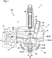
- the figure shows an embodiment of a device 100 for the additive manufacturing of three-dimensional workpieces, in particular a 3D metal printer.
- the device 100 comprises a print head 1 and a device 40 for generating an inert atmosphere 22 within the print head 1 by means of a gas 55, in particular inert gas.
- the print head 1 comprises a housing 3, a device 28 for supplying a metal 14 in solid phase, a piston 5, a reservoir 7, 27 with an outlet opening 10 and an actuator device 12 for displacing the piston.
- the reservoir 7, 27 has a melting region 20 and a displacement chamber 21 for a liquid phase 8 of the metal 14, wherein the melting region 20 adjoins the inert atmosphere 22 and is connected to the displacement chamber 21 in such a way that the liquid phase 8 of the metal 14 can be excited to pass through the outlet opening 10 by the displacement of the piston 5.
- the liquid phase 8 of the metal 14 is also referred to as melt 8 and the inert atmosphere 22 is formed by introducing the inert gas 55 into the reservoir 7, 27.
- the introduction of the inert gas 55 preferably takes place via a cold region of the print head 1 into the reservoir 7, 27.
- the housing 3 is designed in several parts, comprising at least a cooling flange 25, the insulating plate 26 and the reservoir 7, 27.
- the device 40 for generating the inert atmosphere 22 is arranged outside the print head 1, and comprises a reservoir 41, in particular a pressure reservoir for the gas 55, at least one means 42, 43 for pressure regulation and a gas line 50, 51, 52.
- the means 42, 43 for pressure regulation is formed from an electric pressure regulation valve 41 and an electrically adjustable throttle 42. It is also possible to use either only the electric pressure regulation valve 42 or only the electrically adjustable throttle 43 to regulate the pressure of the inert atmosphere 22 in the reservoir 7 or inside the print head.
- the gas line 50, 51, 52 of the device 40 for generating the inert atmosphere 22 is connected to the reservoir 7 via a line 53, the line 53 being arranged inside the insulating plate 26 of the print head 1.
- the device 40 for generating the inert atmosphere 22 can be connected to the line 53 of the print head 1 via connection adapters (not shown) by means of the gas line 50, 51, 52 arranged outside the print head 1.
- the line 53 inside the insulating plate 26 is preferably designed as a through hole.
- the piston 5 is made of several parts, comprising at least one piston rod 17 made of a metallic material and a stamp 18 made of ceramic.
- the piston rod 17 extends from the actuator device 12 through the cooling flange 25 and the insulating plate 26 into the reservoir 7, 27, where it merges into the stamp 18.
- the cooling flange 25 has a recess 30 for receiving the actuator device 12, which is designed as a piezoelectric actuator 12.
- the piezoelectric actuator 12 is fixed in the recess 30 during operation in such a way that when a voltage is applied it exerts a working stroke on the piston 5, specifically on the piston rod 17 of the piston.
- the piston rod 17 transfers the working stroke to the plunger 18 so that the latter stimulates the liquid phase 8 of the metal 14 to pass through the outlet opening 10.
- the piston 5 can be returned to an initial position by a spring 13 without actuating the actuator 12, the spring 13 being arranged in the recess 30 of the cooling flange 25 between a shoulder 24 and the actuator 12.
- the spring 13 is designed as a disc spring.
- the cooling flange 25 also has cooling channels 31 for cooling.
- the cooling channels 31 are arranged between the cooling flange 25 and the insulating plate 26 and are flushed with a cooling medium. This serves as cooling against the heating by the melt 8 and for cooling the actuator 12 during operation.
- the cooling flange 25 is made of a metallic material.
- the insulating plate 26 adjacent to the cooling flange 25 on the side of the cooling channels 31 is made of a heat-insulating material and designed such that it reduces heat transfer from the reservoir 7, 27 to the cooling flange 25.
- the device 28 for supplying the metal 14 opens into the reservoir 7, 27 and is arranged in the cooling flange 25 and the insulating plate 26.
- the device 28 projects through the cooling flange 25 and the insulating plate 26 and the metal 14, or the material 14 to be printed, can be supplied from the outside through the device 28. Pre-dosed pieces of material or pellets can preferably be used.
- the opening 29 can be closed by a device 32 so that it is preferably only open when the material 14 is supplied, thereby reducing the escape of energy or gas from the inert atmosphere 22.
- the reservoir 7, 27 is designed as a melting pot 27, with an inductor 35 being arranged outside the melting pot 27 and a sensor 36, in particular a temperature sensor, being arranged inside the melting pot. Between the An insulator (not shown) may optionally be located between the melting crucible 27 and the inductor 35 or the inductor coil 35.
- the metal 14 enters the melting region 20 of the crucible in a solid phase 14 and is heated by the inductor 35 until it changes into a liquid phase 8.
- the pressure head 1 can start operating.
- the liquid phase 8, or the melt 8 passes the stamp 18 into the displacement chamber 21 due to the gravitational pressure of the melt 8 or a combination of gravitational pressure and atmospheric pressure of the inert gas 22.
- the stamp 18 of the piston 5 is in the melt 8 or surrounded by melt 8 with a pressure side 19 and is in the inert atmosphere 22 or surrounded by the inert atmosphere 22 on the connection side to the piston rod 17.
- the piston rod 17 does not come into contact with the melt 8 due to the process.
- the ceramic of the plunger 18 is advantageously very good thermal conductor in order to be able to transfer the heat generated by the inductor 35 well into the displacement chamber 21.
- the pressure side 19 of the stamp 18 exerts pressure on the melt 8 in the displacement chamber 21 in the direction of the outlet opening 10 and ensures that a drop 15 is ejected through the outlet opening 10 of the reservoir 7, 27, or the displacement chamber 21.
- the outlet opening 10 is designed for the ejection of drops 15 of the liquid phase 8 of the metal 14, wherein the outlet opening 10 has the shape of a nozzle 10 and can be firmly connected to the crucible 27, or as shown in the embodiment, has an exchangeable insert 11 that allows the use of different nozzle geometries.
- the inert atmosphere 22 within the reservoir 7 has a higher pressure P i during operation than an ambient pressure P a outside the print head 1, wherein the pressure P i can be regulated via the at least one means 42, 43 for pressure regulation.
- the invention covers a method for operating the device 100 for additive manufacturing.
- the pressure P i of the inert atmosphere 22 is regulated or adjusted via the pressure control means 42, 43 in such a way that the pressure P i is above the ambient pressure P a and below a limit pressure which causes or would cause an emission of drops 15 through the outlet opening 10.
- the pressure P i is below a limit pressure that would cause drops 15 to be ejected from the outlet opening 10 of the print head 1 without the piston 5 exerting a stroke or a pressure pulse on the melt 8.
- the pressure P i of the inert atmosphere 22, which is to be set by the means 42, 43 for pressure control, depends, for example, on the metal 14 to be processed and the resulting viscosity of the melt 8. Furthermore, it also depends on the size of the outlet opening 10.
- the pressure P i is adjusted so that only drops 15 are ejected when the piston 5 is acted upon by the actuator 12.
- the pressure P i of the inert atmosphere 22 is regulated or adjusted via the means 42, 43 for pressure control such that the pressure P i is above the ambient pressure P a and above the limit pressure which causes droplets 15 to be emitted through the outlet opening 10, so that the liquid phase 8 of the metal 14 is emitted through the outlet opening 10 by the pressure exerted by the inert atmosphere 22.
- the higher pressure P i of the inert atmosphere relative to the ambient pressure P a offers the possibility that the print head 1 generates a continuous ejection of the liquid phase 8 of the metal 14, or the melt 8, wherein the pressure P i of the inert atmosphere 22 is above a limit pressure for the ejection of drops 15 in such a way that the liquid phase 8 of the metal 14, or the Melt 8 can be pressed from the outlet opening 10 into a cavity of a workpiece.
- the stroke or the pressure pulse of the piston 5 on the melt 8 is interrupted for this process.
- the piston 15 can be positioned both in and outside the melt 8 during the filling of the workpiece. This method enables areas in a workpiece or in a 3D printed part to be filled very quickly, which can reduce the total printing time for a workpiece.
- the first method step is used to produce the workpiece by emitting individual drops 15 and the second method step is used to fill the workpiece, in particular a cavity of a workpiece.
- the pressure P i of the inert Atmosphere 22 is regulated via the means 42, 43 for pressure control such that the pressure P i is above the ambient pressure P a and above the limit pressure which causes an emission of drops 15 through the outlet opening 10, so that the liquid phase 8 of the metal 14 is emitted through the outlet opening 10 by the pressure exerted by the inert atmosphere 22, the reservoir 7 and the displacement chamber 21 being flushed by the gas 55.
- the emptying of the print head 1, or the reservoir 7 and the displacement chamber 21, takes place by flushing the melt 8 still in the print head 1, preferably at the end of a printing process, from the print head 1, or the reservoir 7 and the displacement chamber 21, by introducing the inert gas 55 with the pressure P i , or the overpressure, with respect to the ambient pressure P a of the print head 1, into the print head 1. This avoids stresses occurring during the cooling and hardening of the melt 8 in the components of the print head 1 that come into contact with the melt 8.
Landscapes
- Engineering & Computer Science (AREA)
- Chemical & Material Sciences (AREA)
- Materials Engineering (AREA)
- Manufacturing & Machinery (AREA)
- Mechanical Engineering (AREA)
- Physics & Mathematics (AREA)
- Optics & Photonics (AREA)
- Health & Medical Sciences (AREA)
- Toxicology (AREA)
- Automation & Control Theory (AREA)
- Environmental & Geological Engineering (AREA)
- Powder Metallurgy (AREA)
Claims (1)
- Procédé d'exploitation d'un dispositif (100) pour la fabrication additive de pièces tridimensionnelles, pendant une opération d'impression pour la fabrication d'une pièce par émission de gouttes individuelles (15) et remplissage, le dispositif (100) étant une imprimante 3D à métal, comprenant une tête d'impression (1) et un dispositif (40) pour générer une atmosphère inerte (22) à l'intérieur de la tête d'impression (1) par un gaz (55), notamment un gaz inerte, la tête d'impression (1) comprenant un boîtier (3), un dispositif (28) pour amener un métal (14), un piston (5), un réservoir (7) avec une ouverture de sortie (10) et un dispositif d'actionnement (12) pour déplacer le piston (5), le réservoir (7) présentant une zone de fusion (20) et une chambre de refoulement (21) pour une phase liquide (8) du métal (14), la zone de fusion (20) étant adjacente à l'atmosphère inerte (22) et reliée à la chambre de refoulement (21) de telle sorte que le déplacement du piston (5) permet d'inciter la phase liquide (8) du métal (14) à traverser l'ouverture de sortie (10), le dispositif (40) de génération de l'atmosphère inerte (22) étant agencé à l'extérieur de la tête d'impression (1), comprenant un accumulateur (41), au moins un moyen (42, 43) de régulation de pression et une conduite de gaz (50, 51, 52),
caractérisé en ce que
pour la fabrication de la pièce par émission de gouttes individuelles (15), la pression (Pi) de l'atmosphère inerte (22) est régulée par le moyen de régulation de pression (42, 43) de telle sorte que la pression (Pi) soit supérieure à la pression ambiante (Pa) et inférieure à une pression limite qui provoque une émission de gouttes (15) à travers l'ouverture de sortie (10) et, pour le remplissage de la pièce, notamment d'une cavité d'une pièce, la pression (Pi) de l'atmosphère inerte (22) est régulée par le moyen de régulation de pression (42, 43) de telle sorte que la pression (Pi) soit supérieure à la pression ambiante (Pa) et à la pression limite qui provoque l'émission de gouttes (15) à travers l'ouverture de sortie (10), de telle sorte que la phase liquide (8) du métal (14) est émise à travers l'ouverture de sortie (10) par la pression exercée par l'atmosphère inerte (22) .
Applications Claiming Priority (2)
| Application Number | Priority Date | Filing Date | Title |
|---|---|---|---|
| DE102017222162.3A DE102017222162A1 (de) | 2017-12-07 | 2017-12-07 | Vorrichtung zur additiven Fertigung von dreidimensionalen Werkstücken und Verfahren zum Betreiben einer Vorrichtung zur additiven Fertigung von dreidimensionalen Werkstücken |
| PCT/EP2018/078035 WO2019110170A1 (fr) | 2017-12-07 | 2018-10-15 | Dispositif pour la fabrication additive de pièces tridimensionnelles et procédé pour le fonctionnement d'un dispositif pour la fabrication additive de pièces tridimensionnelles |
Publications (3)
| Publication Number | Publication Date |
|---|---|
| EP3720632A1 EP3720632A1 (fr) | 2020-10-14 |
| EP3720632B1 true EP3720632B1 (fr) | 2024-05-15 |
| EP3720632C0 EP3720632C0 (fr) | 2024-05-15 |
Family
ID=63915010
Family Applications (1)
| Application Number | Title | Priority Date | Filing Date |
|---|---|---|---|
| EP18789353.2A Active EP3720632B1 (fr) | 2017-12-07 | 2018-10-15 | Procédé pour le fonctionnement d'un dispositif pour la fabrication additive de pièces tridimensionnelles |
Country Status (5)
| Country | Link |
|---|---|
| US (1) | US11518084B2 (fr) |
| EP (1) | EP3720632B1 (fr) |
| CN (1) | CN111448019A (fr) |
| DE (1) | DE102017222162A1 (fr) |
| WO (1) | WO2019110170A1 (fr) |
Families Citing this family (9)
| Publication number | Priority date | Publication date | Assignee | Title |
|---|---|---|---|---|
| DE102017221959A1 (de) * | 2017-11-27 | 2019-05-29 | Robert Bosch Gmbh | Kolben für einen Druckkopf eines 3D-Druckers und Druckkopf für einen 3D-Drucker |
| EP4356877B1 (fr) | 2018-11-12 | 2025-06-04 | Össur Iceland EHF | Dispositif médical comprenant une structure à base de filaments |
| EP4678145A3 (fr) | 2019-11-12 | 2026-03-04 | Ossur Iceland Ehf | Doublure de prothèse ventilée |
| US11396063B2 (en) * | 2020-03-23 | 2022-07-26 | Rosemount Aerospace Inc. | Systems and methods for in process heating for direct energy deposition applications |
| US11752663B2 (en) * | 2020-09-30 | 2023-09-12 | Ut-Battelle, Llc | Precision bead forming 3D print head for cementitious materials |
| CN112659543A (zh) * | 2020-11-19 | 2021-04-16 | 苏州浩海清创生物科技有限公司 | 一种容积驱动3d打印流涎控制方法 |
| DE102021116623A1 (de) | 2021-06-28 | 2022-12-29 | Grob-Werke Gmbh & Co. Kg | Druckkopf und Verfahren zur additiven Fertigung eines Bauteils mittels Metallschmelze |
| CN115007881A (zh) * | 2022-06-16 | 2022-09-06 | 广东省科学院智能制造研究所 | 旋转挤压装置、复合增材制造系统及方法 |
| CN119426625A (zh) * | 2024-10-29 | 2025-02-14 | 北京理工大学 | 一种基于冷坩埚悬浮熔炼的微滴喷射增材制造装置 |
Family Cites Families (7)
| Publication number | Priority date | Publication date | Assignee | Title |
|---|---|---|---|---|
| EP1803567A1 (fr) * | 2005-12-27 | 2007-07-04 | Nederlandse Organisatie voor toegepast-natuurwetenschappelijk Onderzoek TNO | Système de jets de matériau |
| CN103636101A (zh) | 2011-06-30 | 2014-03-12 | 佩西蒙技术公司 | 结构化的磁性材料 |
| CN103056367B (zh) | 2012-12-29 | 2015-07-29 | 大连理工大学 | 一种基于脉冲小孔液滴喷射三维快速成型的方法及装置 |
| US10315247B2 (en) * | 2015-09-24 | 2019-06-11 | Markforged, Inc. | Molten metal jetting for additive manufacturing |
| CN105945285B (zh) * | 2016-05-17 | 2018-03-02 | 江西省科学院应用物理研究所 | 一种均匀金属液滴制备点阵结构零件的方法与装置 |
| CN106424735B (zh) | 2016-10-12 | 2018-11-27 | 北京机科国创轻量化科学研究院有限公司 | 一种液体筛选式金属3d打印喷头 |
| DE102016224047A1 (de) | 2016-12-02 | 2018-06-07 | Robert Bosch Gmbh | Druckkopf für den 3D-Druck von Metallen |
-
2017
- 2017-12-07 DE DE102017222162.3A patent/DE102017222162A1/de not_active Withdrawn
-
2018
- 2018-10-15 US US16/769,888 patent/US11518084B2/en active Active
- 2018-10-15 CN CN201880078881.5A patent/CN111448019A/zh active Pending
- 2018-10-15 EP EP18789353.2A patent/EP3720632B1/fr active Active
- 2018-10-15 WO PCT/EP2018/078035 patent/WO2019110170A1/fr not_active Ceased
Also Published As
| Publication number | Publication date |
|---|---|
| DE102017222162A1 (de) | 2019-06-13 |
| US20210162651A1 (en) | 2021-06-03 |
| EP3720632A1 (fr) | 2020-10-14 |
| WO2019110170A1 (fr) | 2019-06-13 |
| EP3720632C0 (fr) | 2024-05-15 |
| US11518084B2 (en) | 2022-12-06 |
| CN111448019A (zh) | 2020-07-24 |
Similar Documents
| Publication | Publication Date | Title |
|---|---|---|
| EP3720632B1 (fr) | Procédé pour le fonctionnement d'un dispositif pour la fabrication additive de pièces tridimensionnelles | |
| DE102016224047A1 (de) | Druckkopf für den 3D-Druck von Metallen | |
| EP3013502B1 (fr) | Procédé et machine de traitement de fabrication additive d'un élément tridimensionnel par fusion sélective par laser | |
| EP3717152B1 (fr) | Tête d'impression pour imprimante 3d | |
| WO2018167209A1 (fr) | Tête d'impression conçue pour l'impression 3d de métaux | |
| DE3000486A1 (de) | Spritzgussvorrichtung und spritzgussverfahren | |
| DE102014226425A1 (de) | 3D-Drucker für metallische Materialien | |
| EP0752294A2 (fr) | Méthode et appareil d'applicage de plomb liquide | |
| WO2020120317A1 (fr) | Tête d'impression destinée à l'impression 3d de métaux, dispositif d'impression 3d de pièces tridimensionnelles comprenant une tête d'impression, et procédé de fonctionnement d'un dispositif | |
| DE3546148A1 (de) | Vorrichtung zur herstellung von verbundwerkstoff | |
| DE112005003693T5 (de) | Druckzelle und Druckkopf zum Drucken geschmolzener Metalle | |
| WO2019101436A1 (fr) | Tête d'impression pour imprimante 3d et procédé de mise en service d'une tête d'impression d'une imprimante 3d | |
| EP3488951B1 (fr) | Tête d'impression pour une imprimante tridimensionnelle | |
| EP4076797B1 (fr) | Tête d'impression pour impression 3d de métaux | |
| DE102015100861B4 (de) | Heißkanal für eine Druckgussvorrichtung und Betriebsverfahren dafür | |
| EP4023364B1 (fr) | Dispositif et procédé de fabrication de pièces métalliques et/ou céramiques | |
| DE102018216714A1 (de) | Druckkopf für den 3D-Druck von Metallen | |
| DE102019219854A1 (de) | Druckkopf für den 3D-Druck von Metallen | |
| DE10327892B3 (de) | Vorrichtung zum Pressen von dentalkeramischer Masse für die Herstellung von Zahnersatz, wie Kronen, Brücken, Inlays , sowie eine Kolben-Muffelanordnung für eine solche Vorrichtung | |
| WO2022258168A1 (fr) | Tête d'impression pour impression 3d de métaux | |
| DE102019219850A1 (de) | Druckkopf für den 3D-Druck von Metallen | |
| DE102018216773A1 (de) | Druckkopf für den 3D-Druck von Metallen | |
| DE102017222494A1 (de) | Druckkopf zur additiven Fertigung von dreidimensionalen Werkstücken und Verfahren zum Betreiben eines Druckkopfes | |
| DE102019209643A1 (de) | Druckkopf für den 3D-Druck von Metallen | |
| EP4542156A1 (fr) | Dispositif à haute température, en particulier dispositif de fusion à haute température, en particulier pour la fusion d'un métal réfractaire ou d'un composé métallique réfractaire |
Legal Events
| Date | Code | Title | Description |
|---|---|---|---|
| STAA | Information on the status of an ep patent application or granted ep patent |
Free format text: STATUS: UNKNOWN |
|
| STAA | Information on the status of an ep patent application or granted ep patent |
Free format text: STATUS: THE INTERNATIONAL PUBLICATION HAS BEEN MADE |
|
| PUAI | Public reference made under article 153(3) epc to a published international application that has entered the european phase |
Free format text: ORIGINAL CODE: 0009012 |
|
| STAA | Information on the status of an ep patent application or granted ep patent |
Free format text: STATUS: REQUEST FOR EXAMINATION WAS MADE |
|
| 17P | Request for examination filed |
Effective date: 20200707 |
|
| AK | Designated contracting states |
Kind code of ref document: A1 Designated state(s): AL AT BE BG CH CY CZ DE DK EE ES FI FR GB GR HR HU IE IS IT LI LT LU LV MC MK MT NL NO PL PT RO RS SE SI SK SM TR |
|
| AX | Request for extension of the european patent |
Extension state: BA ME |
|
| DAV | Request for validation of the european patent (deleted) | ||
| DAX | Request for extension of the european patent (deleted) | ||
| P01 | Opt-out of the competence of the unified patent court (upc) registered |
Effective date: 20230509 |
|
| REG | Reference to a national code |
Ref country code: DE Ref legal event code: R079 Free format text: PREVIOUS MAIN CLASS: B22F0003105000 Ipc: B05B0001000000 Ref document number: 502018014624 Country of ref document: DE |
|
| GRAP | Despatch of communication of intention to grant a patent |
Free format text: ORIGINAL CODE: EPIDOSNIGR1 |
|
| STAA | Information on the status of an ep patent application or granted ep patent |
Free format text: STATUS: GRANT OF PATENT IS INTENDED |
|
| RIC1 | Information provided on ipc code assigned before grant |
Ipc: B22F 12/53 20210101ALN20231123BHEP Ipc: B22F 10/32 20210101ALI20231123BHEP Ipc: B22F 10/22 20210101ALI20231123BHEP Ipc: B22F 3/00 20060101ALI20231123BHEP Ipc: B22D 23/00 20060101ALI20231123BHEP Ipc: B29C 64/393 20170101ALI20231123BHEP Ipc: B33Y 10/00 20150101ALI20231123BHEP Ipc: B41J 2/00 20060101ALI20231123BHEP Ipc: B05B 1/00 20060101AFI20231123BHEP |
|
| INTG | Intention to grant announced |
Effective date: 20231205 |
|
| GRAS | Grant fee paid |
Free format text: ORIGINAL CODE: EPIDOSNIGR3 |
|
| GRAA | (expected) grant |
Free format text: ORIGINAL CODE: 0009210 |
|
| STAA | Information on the status of an ep patent application or granted ep patent |
Free format text: STATUS: THE PATENT HAS BEEN GRANTED |
|
| AK | Designated contracting states |
Kind code of ref document: B1 Designated state(s): AL AT BE BG CH CY CZ DE DK EE ES FI FR GB GR HR HU IE IS IT LI LT LU LV MC MK MT NL NO PL PT RO RS SE SI SK SM TR |
|
| REG | Reference to a national code |
Ref country code: CH Ref legal event code: EP |
|
| REG | Reference to a national code |
Ref country code: DE Ref legal event code: R096 Ref document number: 502018014624 Country of ref document: DE |
|
| REG | Reference to a national code |
Ref country code: IE Ref legal event code: FG4D Free format text: LANGUAGE OF EP DOCUMENT: GERMAN |
|
| U01 | Request for unitary effect filed |
Effective date: 20240614 |
|
| U07 | Unitary effect registered |
Designated state(s): AT BE BG DE DK EE FI FR IT LT LU LV MT NL PT SE SI Effective date: 20240624 |
|
| P04 | Withdrawal of opt-out of the competence of the unified patent court (upc) registered |
Free format text: CASE NUMBER: APP_36719/2024 Effective date: 20240619 |
|
| PG25 | Lapsed in a contracting state [announced via postgrant information from national office to epo] |
Ref country code: IS Free format text: LAPSE BECAUSE OF FAILURE TO SUBMIT A TRANSLATION OF THE DESCRIPTION OR TO PAY THE FEE WITHIN THE PRESCRIBED TIME-LIMIT Effective date: 20240915 |
|
| PG25 | Lapsed in a contracting state [announced via postgrant information from national office to epo] |
Ref country code: HR Free format text: LAPSE BECAUSE OF FAILURE TO SUBMIT A TRANSLATION OF THE DESCRIPTION OR TO PAY THE FEE WITHIN THE PRESCRIBED TIME-LIMIT Effective date: 20240515 |
|
| PG25 | Lapsed in a contracting state [announced via postgrant information from national office to epo] |
Ref country code: GR Free format text: LAPSE BECAUSE OF FAILURE TO SUBMIT A TRANSLATION OF THE DESCRIPTION OR TO PAY THE FEE WITHIN THE PRESCRIBED TIME-LIMIT Effective date: 20240816 |
|
| PG25 | Lapsed in a contracting state [announced via postgrant information from national office to epo] |
Ref country code: ES Free format text: LAPSE BECAUSE OF FAILURE TO SUBMIT A TRANSLATION OF THE DESCRIPTION OR TO PAY THE FEE WITHIN THE PRESCRIBED TIME-LIMIT Effective date: 20240515 |
|
| PG25 | Lapsed in a contracting state [announced via postgrant information from national office to epo] |
Ref country code: PL Free format text: LAPSE BECAUSE OF FAILURE TO SUBMIT A TRANSLATION OF THE DESCRIPTION OR TO PAY THE FEE WITHIN THE PRESCRIBED TIME-LIMIT Effective date: 20240515 |
|
| PG25 | Lapsed in a contracting state [announced via postgrant information from national office to epo] |
Ref country code: PL Free format text: LAPSE BECAUSE OF FAILURE TO SUBMIT A TRANSLATION OF THE DESCRIPTION OR TO PAY THE FEE WITHIN THE PRESCRIBED TIME-LIMIT Effective date: 20240515 Ref country code: NO Free format text: LAPSE BECAUSE OF FAILURE TO SUBMIT A TRANSLATION OF THE DESCRIPTION OR TO PAY THE FEE WITHIN THE PRESCRIBED TIME-LIMIT Effective date: 20240815 Ref country code: IS Free format text: LAPSE BECAUSE OF FAILURE TO SUBMIT A TRANSLATION OF THE DESCRIPTION OR TO PAY THE FEE WITHIN THE PRESCRIBED TIME-LIMIT Effective date: 20240915 Ref country code: HR Free format text: LAPSE BECAUSE OF FAILURE TO SUBMIT A TRANSLATION OF THE DESCRIPTION OR TO PAY THE FEE WITHIN THE PRESCRIBED TIME-LIMIT Effective date: 20240515 Ref country code: GR Free format text: LAPSE BECAUSE OF FAILURE TO SUBMIT A TRANSLATION OF THE DESCRIPTION OR TO PAY THE FEE WITHIN THE PRESCRIBED TIME-LIMIT Effective date: 20240816 Ref country code: ES Free format text: LAPSE BECAUSE OF FAILURE TO SUBMIT A TRANSLATION OF THE DESCRIPTION OR TO PAY THE FEE WITHIN THE PRESCRIBED TIME-LIMIT Effective date: 20240515 Ref country code: RS Free format text: LAPSE BECAUSE OF FAILURE TO SUBMIT A TRANSLATION OF THE DESCRIPTION OR TO PAY THE FEE WITHIN THE PRESCRIBED TIME-LIMIT Effective date: 20240815 |
|
| U20 | Renewal fee for the european patent with unitary effect paid |
Year of fee payment: 7 Effective date: 20241028 |
|
| P05 | Withdrawal of opt-out of the competence of the unified patent court (upc) changed |
Free format text: CASE NUMBER: APP_36719/2024 Effective date: 20240624 |
|
| PG25 | Lapsed in a contracting state [announced via postgrant information from national office to epo] |
Ref country code: CZ Free format text: LAPSE BECAUSE OF FAILURE TO SUBMIT A TRANSLATION OF THE DESCRIPTION OR TO PAY THE FEE WITHIN THE PRESCRIBED TIME-LIMIT Effective date: 20240515 |
|
| PG25 | Lapsed in a contracting state [announced via postgrant information from national office to epo] |
Ref country code: SK Free format text: LAPSE BECAUSE OF FAILURE TO SUBMIT A TRANSLATION OF THE DESCRIPTION OR TO PAY THE FEE WITHIN THE PRESCRIBED TIME-LIMIT Effective date: 20240515 Ref country code: RO Free format text: LAPSE BECAUSE OF FAILURE TO SUBMIT A TRANSLATION OF THE DESCRIPTION OR TO PAY THE FEE WITHIN THE PRESCRIBED TIME-LIMIT Effective date: 20240515 |
|
| PG25 | Lapsed in a contracting state [announced via postgrant information from national office to epo] |
Ref country code: SM Free format text: LAPSE BECAUSE OF FAILURE TO SUBMIT A TRANSLATION OF THE DESCRIPTION OR TO PAY THE FEE WITHIN THE PRESCRIBED TIME-LIMIT Effective date: 20240515 |
|
| PG25 | Lapsed in a contracting state [announced via postgrant information from national office to epo] |
Ref country code: SM Free format text: LAPSE BECAUSE OF FAILURE TO SUBMIT A TRANSLATION OF THE DESCRIPTION OR TO PAY THE FEE WITHIN THE PRESCRIBED TIME-LIMIT Effective date: 20240515 Ref country code: SK Free format text: LAPSE BECAUSE OF FAILURE TO SUBMIT A TRANSLATION OF THE DESCRIPTION OR TO PAY THE FEE WITHIN THE PRESCRIBED TIME-LIMIT Effective date: 20240515 Ref country code: RO Free format text: LAPSE BECAUSE OF FAILURE TO SUBMIT A TRANSLATION OF THE DESCRIPTION OR TO PAY THE FEE WITHIN THE PRESCRIBED TIME-LIMIT Effective date: 20240515 Ref country code: CZ Free format text: LAPSE BECAUSE OF FAILURE TO SUBMIT A TRANSLATION OF THE DESCRIPTION OR TO PAY THE FEE WITHIN THE PRESCRIBED TIME-LIMIT Effective date: 20240515 |
|
| REG | Reference to a national code |
Ref country code: DE Ref legal event code: R097 Ref document number: 502018014624 Country of ref document: DE |
|
| PLBE | No opposition filed within time limit |
Free format text: ORIGINAL CODE: 0009261 |
|
| STAA | Information on the status of an ep patent application or granted ep patent |
Free format text: STATUS: NO OPPOSITION FILED WITHIN TIME LIMIT |
|
| 26N | No opposition filed |
Effective date: 20250218 |
|
| REG | Reference to a national code |
Ref country code: CH Ref legal event code: PL |
|
| GBPC | Gb: european patent ceased through non-payment of renewal fee |
Effective date: 20241015 |
|
| PG25 | Lapsed in a contracting state [announced via postgrant information from national office to epo] |
Ref country code: MC Free format text: LAPSE BECAUSE OF FAILURE TO SUBMIT A TRANSLATION OF THE DESCRIPTION OR TO PAY THE FEE WITHIN THE PRESCRIBED TIME-LIMIT Effective date: 20240515 |
|
| PG25 | Lapsed in a contracting state [announced via postgrant information from national office to epo] |
Ref country code: GB Free format text: LAPSE BECAUSE OF NON-PAYMENT OF DUE FEES Effective date: 20241015 |
|
| PG25 | Lapsed in a contracting state [announced via postgrant information from national office to epo] |
Ref country code: CH Free format text: LAPSE BECAUSE OF NON-PAYMENT OF DUE FEES Effective date: 20241031 |
|
| PG25 | Lapsed in a contracting state [announced via postgrant information from national office to epo] |
Ref country code: IE Free format text: LAPSE BECAUSE OF NON-PAYMENT OF DUE FEES Effective date: 20241015 |
|
| U20 | Renewal fee for the european patent with unitary effect paid |
Year of fee payment: 8 Effective date: 20251027 |
|
| PG25 | Lapsed in a contracting state [announced via postgrant information from national office to epo] |
Ref country code: CY Free format text: LAPSE BECAUSE OF FAILURE TO SUBMIT A TRANSLATION OF THE DESCRIPTION OR TO PAY THE FEE WITHIN THE PRESCRIBED TIME-LIMIT; INVALID AB INITIO Effective date: 20181015 |
|
| PG25 | Lapsed in a contracting state [announced via postgrant information from national office to epo] |
Ref country code: HU Free format text: LAPSE BECAUSE OF FAILURE TO SUBMIT A TRANSLATION OF THE DESCRIPTION OR TO PAY THE FEE WITHIN THE PRESCRIBED TIME-LIMIT; INVALID AB INITIO Effective date: 20181015 |