EP3720660B1 - Outils de soins de sol - Google Patents
Outils de soins de sol Download PDFInfo
- Publication number
- EP3720660B1 EP3720660B1 EP18821937.2A EP18821937A EP3720660B1 EP 3720660 B1 EP3720660 B1 EP 3720660B1 EP 18821937 A EP18821937 A EP 18821937A EP 3720660 B1 EP3720660 B1 EP 3720660B1
- Authority
- EP
- European Patent Office
- Prior art keywords
- floor care
- care tool
- handle
- clip
- housing
- Prior art date
- Legal status (The legal status is an assumption and is not a legal conclusion. Google has not performed a legal analysis and makes no representation as to the accuracy of the status listed.)
- Active
Links
Images









Classifications
-
- A—HUMAN NECESSITIES
- A47—FURNITURE; DOMESTIC ARTICLES OR APPLIANCES; COFFEE MILLS; SPICE MILLS; SUCTION CLEANERS IN GENERAL
- A47L—DOMESTIC WASHING OR CLEANING; SUCTION CLEANERS IN GENERAL
- A47L13/00—Implements for cleaning floors, carpets, furniture, walls, or wall coverings
- A47L13/10—Scrubbing; Scouring; Cleaning; Polishing
- A47L13/50—Auxiliary implements
- A47L13/52—Dust pans; Crumb trays
-
- A—HUMAN NECESSITIES
- A46—BRUSHWARE
- A46B—BRUSHES
- A46B15/00—Other brushes; Brushes with additional arrangements
-
- A—HUMAN NECESSITIES
- A46—BRUSHWARE
- A46B—BRUSHES
- A46B15/00—Other brushes; Brushes with additional arrangements
- A46B15/0055—Brushes combined with other articles normally separate from the brushing process, e.g. combs, razors, mirrors
-
- A—HUMAN NECESSITIES
- A46—BRUSHWARE
- A46B—BRUSHES
- A46B17/00—Accessories for brushes
- A46B17/02—Devices for holding brushes in use
-
- A—HUMAN NECESSITIES
- A47—FURNITURE; DOMESTIC ARTICLES OR APPLIANCES; COFFEE MILLS; SPICE MILLS; SUCTION CLEANERS IN GENERAL
- A47L—DOMESTIC WASHING OR CLEANING; SUCTION CLEANERS IN GENERAL
- A47L13/00—Implements for cleaning floors, carpets, furniture, walls, or wall coverings
- A47L13/10—Scrubbing; Scouring; Cleaning; Polishing
- A47L13/50—Auxiliary implements
- A47L13/51—Storing of cleaning tools, e.g. containers therefor
- A47L13/512—Clamping devices for hanging the tools
-
- B—PERFORMING OPERATIONS; TRANSPORTING
- B25—HAND TOOLS; PORTABLE POWER-DRIVEN TOOLS; MANIPULATORS
- B25G—HANDLES FOR HAND IMPLEMENTS
- B25G1/00—Handle constructions
- B25G1/10—Handle constructions characterised by material or shape
-
- A—HUMAN NECESSITIES
- A46—BRUSHWARE
- A46B—BRUSHES
- A46B2200/00—Brushes characterized by their functions, uses or applications
- A46B2200/30—Brushes for cleaning or polishing
- A46B2200/302—Broom
Definitions
- the dustpan and the dustpan shadoof can be folded and the broom shadoof is bucked on the dustpan shadoof; therefore, the size of the device is reduced and the occupied space is decreased.
- known systems may not be able to be stored in a convenient manner.
- the components may be propped against a wall or in a corner, or may be crudely hung to a hook or other wall attachment.
- the floor care tools may be complementary style tools that may be attached to one another to store or otherwise move said tools.
- complementary tools are tools that may be used in conjunction with one another and therefore, it maybe be advantageous to make sure that the tools stay together when not in use.
- tools may include, but are not limited to, a broom and a receptacle, such as a dust pan.
- the tools are complementary in that the broom is used to sweep matter, such as particulate matter, trash, or the like, and then the broom moves the matter into the dust pan receptacle for emptying into a larger receptacle at a later time.
- matter such as particulate matter, trash, or the like
- the tools are used in conjunction with one another, they are considered complementary. Therefore, aspects and embodiments of the present disclosure provide for ways to maintain the combination of such complementary tools.
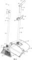
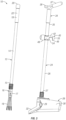
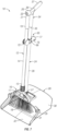
- Figures 1-4 show various views of complementary tools being connected and disconnected from one another according to the aspects of the present disclosure. While particular types of complementary tools are shown in the figures, it should be contemplated and envisioned that these not be limiting on the disclosure, and that aspects of the disclosure can be used with generally any type of tools to which it is desired to attach or otherwise store together.
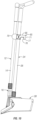
- the figures show a floor care tool set 10.
- the floor care tool set 10 includes first and second floor care tools 12, 24.
- the first floor care tool 12 is shown to be a broom.
- the broom includes an elongated handle 14 having a first end 15 and a second end 19.
- At or near the first end 15 of the elongated handle 14 is a tool head 16.
- the tool head 16 includes a frame 17 to which are attached bristles 18.
- a broom is shown as the first floor care tool 12, it should be envisioned that generally any type of floor care tool can be utilized. Examples of such floor care tools may be found in co-owned U.S. Application No. 14/996,993 .
- the floor care tool may also be connected to the handle in a manner separate from that disclosed in the '993 disclosure.
- the tool head may be connected without threading, and instead be connectable by a fastener such as a snap button (e.g., snap button used with tent pole fasteners) or other tent pole clips.
- a fastener such as a snap button (e.g., snap button used with tent pole fasteners) or other tent pole clips.
- Other snaps, clips, and mechanical fasteners could be used to connect the handle and the tool head or heads.
- an aspect of the disclosure includes the incorporation of a clip 40 attached or otherwise positioned at one of the handles of the first or second floor care tool. This can be at generally any location along the longitudinal length of the handles. As shown in Figures 1-4 , the clip 40 is generally positioned on and about the elongated handle 26 of the second floor care tool 24. However, it should be appreciated that the clip 40 could also be positioned on the handle 14 of the first floor care tool 12 with the components thereof generally reversed. The clip 40 provides for unique aspects for at least temporarily attaching or otherwise affixing the first and second floor care tools 12, 24 such as that shown in Figures 1 and 4 .
- the clip 40 provides for easy separation of the first and second floor care tools 12, 24 such that the use thereof will not be prohibited or otherwise negatived by such use of the clip.
- a clip 40 is provided.
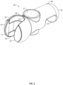
- the clip 40 includes a housing 42.
- the housing 42 may include a first portion 43 and a second portion 44 connected to one another, e.g., by a screw or other mechanical connection.
- the first and second portions 43, 44 of the clip housing 42 can be connected via a groove or slot 46 in the first housing 43 such as to provide orientation and direction for connecting the components of the housing together.
- the first portion 43 of the clip 40 also includes an aperture 47, such as for surrounding or at least partially surrounding a handle of the first or second floor care tools. While the Figures show an aperture almost substantially surrounding the handle, it should be appreciated that the aperture 47 could take the form of a clip being open or otherwise attaching to the elongated handle of the first or second floor care tool.
- the clip is positioned on the second floor care tool handle, while the concave portion is extended to receive a portion of the handle of the first floor care tool.
- the concave portion is configured to receive and at least temporarily hold the handle 14 of the first floor care tool 12 until such time as the components are to be used and can be separated.
- magnets 56, 57 are included, as is shown in Figure 6 .
- the magnets 56, 57 may be enclosed within one or more of the grooves or slots 46 in the first housing portion 43 and enclosed by the second housing portion 44.
- the magnets will interact with the steel of the handle 14 of the first floor care tool 12 to provide a magnetic connection/attraction between the clip 40 and the first floor care tool 12.
- Such magnetic attraction can be overcome by little force, and can be overcome to separate the floor care tools from one another.
- the attraction will provide for the temporary connection between the first and second floor care tools, such as when the tools are not in use. Therefore, the concave portion 50 and the magnetics work together to hold the handle of the first floor care tool within the concave portion 50 of the second floor care tool 24 to temporarily connect the floor care tools as a floor care tool set 10.
- the clip 40 includes a hook or notch member 54.
- the hook or notch member 54 is positioned generally at or near the second end 49 of the housing 42.
- Such a hook or notch portion can be used to receive a lip or lip like surface of a component, such as a trash receptacle, wall, hanging apparatus, or the like. This will provide for a component to hang the floor care tool set 10 on. Therefore, the hook or notch portion can be varied in size, depth, and the like.
- a puck connector 55 portion at the second end 49 is a puck connector 55 portion.
- the puck connector 55 can be utilized to connect the clip 40 to a puck member 93, such as that will be shown and described herein. This provides for additional places to hang the floor care tool set 10, such as when not in use.
- the clip 40 may include a screw aperture 58 for connecting the first and second portions 43, 44 of the housing 42 to connect thereto. Additional screws or apertures thereof can be included to provide attachment of the clip housing 42 to one of the elongated handles.
- Figures 1-4 show the floor care tools 12, 24 in various stages of connecting and disconnecting. As shown in Figures 2 and 3 , the tools are disconnected, such as when they are to be used complementarily.
- Figures 1 and 4 show the tools generally connected to one another, which may be storage or otherwise non-use configuration.
- the handle 14 of the first floor care tool 12 is nestled or partially within the concave portion 50 of the clip 40 and can be maintained therein by use of such magnets.
- a second point of connection is shown by way of the grip 34 of the second floor care tool 24 and the mounting member 20 of the first floor care tool 12.
- the grip 34 includes a beak or other extension portion 36. This is configured to interact or otherwise be inserted into the aperture 22 of the mounting member 20. Such insertion of the beak 36 into the aperture 22 will provide a second point of connection between the first and second floor care tools to provide for additional stability for the connection.
- FIGS 7-10 show additional aspects and/or embodiments of a floor care tool set 60 according to aspects of the present disclosure.
- the floor care tool set 60 shown in Figures 7-10 include many of the same features as that shown and described previously herein.
- The includes the use of the first and second floor care tools and components thereof.
- one change between the floor care tool set 60 and the floor care tool set 10 as previously disclosed is the use of the clip 65.
- the clip 65 is used in generally the same manner as that of the clip 40 as previously shown and described herein.
- the clip 65 includes additional aspects and/or embodiments that differ from the clip as previously shown and described.
- the clip which is shown in greater detail in Figures 11 and 12 , includes a housing 66.
- the housing includes a first portion 67 and a second portion 68.
- the housing portions of the clip 65 are split generally longitudinally along the length of the clip 65. This longitudinal split provides for the first and second housing portion 67, 68 to be generally connected around the handle of one of the first or second floor care tool.
- the housing can be connected to one another about the handle, such as by a screw in the aperture 80. There can be one or more screws, as is shown in the figures.
- the clip 65 includes generally many of the same or similar features as that previously shown and described herein.
- the housing 66 includes the handle aperture 69, which is created by the connection of the first and second housing portions.
- a concave portion or surface 72 is a generally U-shaped or type area which is sized and configured to be able to receive an elongated handle, such as that shown with regard the first floor care tool 12. Therefore, the size and shape are not to be limited to that shown in the figures.
- the concave portion 72 includes a first side and opposite second side 73, 74 and inner most sections 75.
- a magnet 79 which is shown to be generally a cylinder-shaped magnet.
- the magnet 79 is configured to fit between the first and second housing sections within the notch 78, and at or near the inner most section 75 of the concave portion 72.
- the magnet 79 will interact with the handle of a floor care tool position within the concave portion to provide an attraction therein to at least temporarily connect and hold the handle within the concave portion. Therefore, the magnet can take many shapes, forms, and/or sizes, but it is generally used to provide attraction to the handle to provide adherence thereto.
- the rail 91 includes channel portions 92 which can interact with notches of the puck 93 to allow the puck to be slid on to and about the rail 91.
- the puck 93 including a puck body 94 can include a first notch 99, second notch 100, third notch 101, and fourth notch 102.
- the notches are spaced similar to the rail extrusions such that the notches fit on and slide about the rail at the notches.
- the spacing of the notches allow the puck to be placed in different configurations relative to the rail. This can include with the puck being generally positioned below the rail, as is shown in Figure 13 . However, this generally provide for three different configurations or hides the puck relative to the rail system.
- the different heights of the puck relative to the rail can allow for staggering of the floor care tool set 10.
- the puck body 94 includes a receiving portion or pocket 95.
- the receiving portions can interact with the clip to be positioned therein.
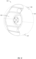
- Figures 14-16 show another aspect of the mounting member, which includes a single puck 103.
- the single puck can be used in conjunction with the puck 93, or in the stand alone manner, such as when attaching a single tool or tool component to a rail or to a position on the wall. For example, this single puck can be used independent of the rail to be adhered to a wall for attachment thereto.
- Such a single puck can therefore be standalone mounted for single use applications, such as attached with an adhesive or mechanical fastener to a particular surface or location without the use for a rail.
- the puck will also include notches 106, 107, for interaction with the rail 91, when used therein. This allows the puck to be slide on the rail into a particular location of choice.
- a pocket 105 allows for interaction with the mounting member 20 or else the connections 55, 77 of the clips 40, 65 to be attaching the floor care tools set thereto.
Landscapes
- Engineering & Computer Science (AREA)
- Mechanical Engineering (AREA)
- Cleaning Implements For Floors, Carpets, Furniture, Walls, And The Like (AREA)
Claims (14)
- Kit d'outils d'entretien de sol (10), comprenant :un premier outil d'entretien de sol (12) comprenant un manche (14) allongé avec une première tête d'outil d'entretien de sol (16) positionnée à une première extrémité (15) du manche (14) ;un second outil d'entretien de sol (24) comprenant un manche (26) allongé et une seconde tête d'outil d'entretien de sol positionnée à une première extrémité (27) du manche (26) ;un élément de montage (20) positionné à une seconde extrémité (19) du manche (14) du premier outil d'entretien de sol ;et une manette (34) positionnée à une seconde extrémité (35) du second outil d'entretien de sol (24), ladite manette (34) comprenant un prolongement (36) qui coupe l'élément de montage (20) du premier outil d'entretien de sol (12) ; et caractérisé en ce qu'il comprend en outre une pince (40) attachée au manche du premier ou du second outil d'entretien de sol (12, 24), ladite pince (40) comprenant un boîtier (42) relié de manière opérationnelle au manche (14) avec ledit boîtier (42) comportant une partie concave (50) pour recevoir une partie du premier ou du second manche (14, 26), et au moins un élément de maintien adapté à la partie concave (50) pour maintenir l'un du premier ou du second manches (14, 26) à l'intérieur de la partie concave (50).
- Kit d'outils d'entretien de sol (10) selon la revendication 1, dans lequel ladite pince (40) est attachée au second outil d'entretien de sol (24), et la partie concave (50) de la pince (40) est configurée pour recevoir une partie du manche (14) du premier outil d'entretien de sol (12).
- Kit d'outils d'entretien de sol (10) selon la revendication 1, dans lequel l'au moins un élément de maintien comprend au moins un aimant (56) positionné de manière opérationnelle par rapport au boîtier de pince (42).
- Kit d'outils d'entretien de sol (10) selon la revendication 3, dans lequel l'au moins un aimant (56) est positionné au ou proche du point le plus intérieur (53) de la partie concave (50).
- Kit d'outils d'entretien de sol (10) selon la revendication 3, dans lequel l'au moins un aimant (56) comprend un premier et un second aimants (56, 57) généralement positionnés vis-à-vis l'un de l'autre et orientés vers l'intérieur par rapport à la partie concave (50).
- Kit d'outils d'entretien de sol (10) selon la revendication 1, dans lequel le manche du premier et du second outils d'entretien de sol (12, 24) comprend de l'acier.
- Kit d'outils d'entretien de sol (10) selon la revendication 1, dans lequel la pince (40) comprend un crochet (54) à l'opposé de la partie concave (50).
- Kit d'outils d'entretien de sol (10) selon la revendication 1, dans lequel la première tête d'outil d'entretien de sol (16) comprend un balai, et le second outil d'entretien de sol (24) comprend un réceptacle (28).
- Kit d'outils d'entretien de sol (10) selon la revendication 1, dans lequel la manette (34) comporte une partie de main allongée (37) à l'opposé du prolongement (36), dans lequel ladite partie de main allongée (37) est configurée pour correspondre à un contour de la main d'un utilisateur.
- En combinaison, un premier outil d'entretien de sol (12) comprenant un manche allongé (14), et un second outil d'entretien de sol (24) comprenant un manche (26) allongé, la combinaison comprenant :
une pince (40) pour relier temporairement le premier et le second outils d'entretien de sol (12, 24), ladite pince (40) comprenant :un boîtier (42) entourant le manche du premier et du second outils d'entretien de sol (12, 24) ;une surface concave (50) s'étendant à partir d'une première extrémité (48) du boîtier (42) ;caractérisé en ce que ladite pince (40) comprend en outre :un crochet (54) généralement orienté vers le bas sur une seconde extrémité (49) du boîtier (42) ; etun élément de maintien positionné de manière opérationnelle par rapport à la surface concave (50) pour relier temporairement le premier et le second outils d'entretien de sol (12, 24) ; etdans lequel l'élément de maintien comprend un premier et un second aimants (56, 57) à l'intérieur du boîtier (42) sur des côtés opposés (51, 52) de la surface concave (50) ;dans lequel le manche (14) du premier outil d'entretien de sol (12) comprend de l'acier. - Combinaison de la revendication 10, dans laquelle le boîtier (42) comprend une première et une seconde sections attachées l'une à l'autre autour d'une partie du manche du premier et du second outils d'entretien de sol (12, 24).
- Combinaison selon la revendication 10, comprenant en outre un élément de suspension, dans lequel ledit élément de suspension peut être relié de manière opérationnelle à la seconde extrémité (49) du boîtier (42) de la pince (40).
- Kit d'outils d'entretien de sol (10), comprenant :un premier outil d'entretien de sol (12) comprenant un manche (14) allongé avec une première tête d'outil d'entretien de sol (16) positionnée à une première extrémité (15) du manche (14) ;un second outil d'entretien de sol (24) comprenant un manche (26) allongé avec une seconde tête d'outil d'entretien de sol à une première extrémité (27) du manche (26) ; etune pince (40) attachée à une partie du manche (26) du second outil d'entretien de sol (24), ladite pince (40) comprenant un boîtier (42) attaché au manche (26), une partie généralement concave (50) s'étendant à partir d'une première extrémité (48),et comprenant en outre une seconde extrémité (49) ;dans lequel la pince (40) relie le premier et le second outils d'entretien de sol (12, 24) en attachant de manière amovible le manche (14) du premier outil d'entretien de sol (12) au moins partiellement à l'intérieur de la partie concave (50) de la pince (40) ;et caractérisé en ce qu'il comprend en outre un élément de maintien associé à la partie concave (50) ;dans lequel la seconde extrémité (49) comporte une encoche ou un crochet (54) ;dans lequel le premier et le second outils d'entretien de sol (12, 24) sont maintenus, au moins partiellement, par l'élément de maintien ; etdans lequel l'élément de maintien comprend un premier et un second aimants (56, 57) sur des côtés intérieurs opposés (51, 52) de la partie concave (50) de la pince (40), et ledit manche (14) du premier outil d'entretien de sol (12) comprenant de l'acier.
- Kit d'outils d'entretien de sol (10) selon la revendication 13, dans lequel ledit premier outil d'entretien de sol (12) comprend un balai et ledit second outil d'entretien de sol (24) comprend un réceptacle (28).
Applications Claiming Priority (2)
| Application Number | Priority Date | Filing Date | Title |
|---|---|---|---|
| US201762594185P | 2017-12-04 | 2017-12-04 | |
| PCT/US2018/063779 WO2019113018A1 (fr) | 2017-12-04 | 2018-12-04 | Outils de soins de sol |
Publications (3)
| Publication Number | Publication Date |
|---|---|
| EP3720660A1 EP3720660A1 (fr) | 2020-10-14 |
| EP3720660B1 true EP3720660B1 (fr) | 2024-12-25 |
| EP3720660C0 EP3720660C0 (fr) | 2024-12-25 |
Family
ID=64734255
Family Applications (1)
| Application Number | Title | Priority Date | Filing Date |
|---|---|---|---|
| EP18821937.2A Active EP3720660B1 (fr) | 2017-12-04 | 2018-12-04 | Outils de soins de sol |
Country Status (8)
| Country | Link |
|---|---|
| US (1) | US10952588B2 (fr) |
| EP (1) | EP3720660B1 (fr) |
| JP (2) | JP7221963B2 (fr) |
| CN (1) | CN111344115B (fr) |
| AU (1) | AU2018381245B2 (fr) |
| CA (1) | CA3083780C (fr) |
| MX (2) | MX2020005698A (fr) |
| WO (1) | WO2019113018A1 (fr) |
Families Citing this family (20)
| Publication number | Priority date | Publication date | Assignee | Title |
|---|---|---|---|---|
| USD898313S1 (en) * | 2018-07-25 | 2020-10-06 | Anthony Corbin | Broom |
| USD945102S1 (en) * | 2018-11-13 | 2022-03-01 | Peter J. Ziamandanis | Extended mop handle |
| US11058213B1 (en) * | 2019-06-06 | 2021-07-13 | Susan C. Macrina | Adaptive brush holder kit |
| KR102086648B1 (ko) * | 2019-08-21 | 2020-03-09 | 주식회사 유니어 | 빗자루가 탈부착되는 쓰레받기 |
| CA3108188C (fr) * | 2021-02-05 | 2023-02-28 | Sheridon Dinnall | Combinaison de balai et de ramasse-poussiere |
| JP1691323S (fr) * | 2021-02-12 | 2021-07-26 | ||
| USD946228S1 (en) * | 2021-04-08 | 2022-03-15 | Shenzhen Gudan Technology Trading Co., Ltd | Broom set |
| KR102859217B1 (ko) * | 2021-11-30 | 2025-09-12 | 정희배 | 기능성 열매 수거 장치 |
| USD977216S1 (en) * | 2022-04-12 | 2023-01-31 | Wuyi Zhisen household products Co., Ltd. | Broom and dustpan set |
| USD1029440S1 (en) * | 2022-06-06 | 2024-05-28 | Supply Source Enterprises, Inc | Dustpan |
| USD1029441S1 (en) * | 2022-04-28 | 2024-05-28 | Supply Source Enterprises, Inc | Dustpan |
| US12029367B2 (en) | 2022-07-06 | 2024-07-09 | Munchkin, Inc. | Magnetic tool set |
| US12527452B2 (en) | 2022-07-06 | 2026-01-20 | Munchkin, Inc. | Magnetic tool set |
| WO2024010584A1 (fr) * | 2022-07-06 | 2024-01-11 | Munchkin, Inc. | Ensemble d'outils magnétiques |
| US12551078B2 (en) | 2022-07-06 | 2026-02-17 | Munchkin, Inc. | Magnetic tool set |
| US12156587B2 (en) * | 2022-08-24 | 2024-12-03 | Michael Allen | Roasting fork cleaning assembly |
| USD1088388S1 (en) * | 2023-03-03 | 2025-08-12 | Hanpeng Yu | Dustpan |
| USD1100400S1 (en) * | 2023-07-13 | 2025-10-28 | Chang'ai Yang | Broom and dustpan set |
| USD1101335S1 (en) * | 2023-07-13 | 2025-11-04 | Chang'ai Yang | Broom and dustpan set |
| USD1101334S1 (en) * | 2023-07-13 | 2025-11-04 | Chang'ai Yang | Broom and dustpan set |
Citations (1)
| Publication number | Priority date | Publication date | Assignee | Title |
|---|---|---|---|---|
| US9532694B1 (en) * | 2013-01-08 | 2017-01-03 | Neli LLC | Combination whisk broom with squeegee |
Family Cites Families (14)
| Publication number | Priority date | Publication date | Assignee | Title |
|---|---|---|---|---|
| US2376955A (en) * | 1944-03-13 | 1945-05-29 | Norris C Ball | Milk pipe rack |
| JPS6051776B2 (ja) * | 1978-02-20 | 1985-11-15 | 日本電子株式会社 | X線発生装置 |
| JPS5628293U (fr) * | 1979-08-13 | 1981-03-17 | ||
| JPH03128054U (fr) * | 1990-04-09 | 1991-12-24 | ||
| US6643891B1 (en) | 2002-01-11 | 2003-11-11 | Wki Holding Company, Inc. | Dustpan with locking handle and associated broom |
| JP2003245228A (ja) | 2002-02-26 | 2003-09-02 | Duskin Co Ltd | 清掃具 |
| US20030167588A1 (en) | 2002-03-07 | 2003-09-11 | Rubbermaid Commercial Products Llc | Cleaning device and method of using same |
| JP3944178B2 (ja) | 2004-03-03 | 2007-07-11 | 山崎産業株式会社 | 清掃用具セット |
| KR200357760Y1 (ko) | 2004-04-14 | 2004-07-30 | 박수근 | 빗자루와 쓰레받기가 결합된 청소용구 |
| JP3128054U (ja) | 2006-10-11 | 2006-12-21 | 一心 蔡 | 吊りカーテン |
| CN202078267U (zh) | 2011-05-31 | 2011-12-21 | 苏国汉 | 一种簸箕扫帚组合装置 |
| CN203841636U (zh) | 2014-05-07 | 2014-09-24 | 黄东生 | 组合式清扫装置 |
| JP6499302B2 (ja) * | 2015-01-16 | 2019-04-10 | エコラボ ユーエスエー インコーポレイティド | 共用ハンドル及び交換式ツールヘッドを備えるツールアセンブリ |
| EP3362228A4 (fr) * | 2015-10-16 | 2019-09-25 | Luna Verktyg & Maskin AB | Porte-outil rapporté |
-
2018
- 2018-12-04 US US16/209,015 patent/US10952588B2/en active Active
- 2018-12-04 EP EP18821937.2A patent/EP3720660B1/fr active Active
- 2018-12-04 CN CN201880073038.8A patent/CN111344115B/zh active Active
- 2018-12-04 MX MX2020005698A patent/MX2020005698A/es unknown
- 2018-12-04 CA CA3083780A patent/CA3083780C/fr active Active
- 2018-12-04 JP JP2020528898A patent/JP7221963B2/ja active Active
- 2018-12-04 AU AU2018381245A patent/AU2018381245B2/en active Active
- 2018-12-04 WO PCT/US2018/063779 patent/WO2019113018A1/fr not_active Ceased
-
2020
- 2020-07-13 MX MX2024003108A patent/MX2024003108A/es unknown
-
2021
- 2021-11-18 JP JP2021187974A patent/JP7291192B2/ja active Active
Patent Citations (1)
| Publication number | Priority date | Publication date | Assignee | Title |
|---|---|---|---|---|
| US9532694B1 (en) * | 2013-01-08 | 2017-01-03 | Neli LLC | Combination whisk broom with squeegee |
Also Published As
| Publication number | Publication date |
|---|---|
| US20190167063A1 (en) | 2019-06-06 |
| JP7221963B2 (ja) | 2023-02-14 |
| CA3083780C (fr) | 2022-05-10 |
| EP3720660C0 (fr) | 2024-12-25 |
| CN111344115A (zh) | 2020-06-26 |
| CA3083780A1 (fr) | 2019-06-13 |
| AU2018381245A1 (en) | 2020-05-28 |
| JP2021504031A (ja) | 2021-02-15 |
| JP2022024107A (ja) | 2022-02-08 |
| EP3720660A1 (fr) | 2020-10-14 |
| MX2020005698A (es) | 2020-08-20 |
| WO2019113018A1 (fr) | 2019-06-13 |
| JP7291192B2 (ja) | 2023-06-14 |
| AU2018381245B2 (en) | 2021-06-24 |
| CN111344115B (zh) | 2023-07-11 |
| US10952588B2 (en) | 2021-03-23 |
| MX2024003108A (es) | 2024-04-05 |
Similar Documents
| Publication | Publication Date | Title |
|---|---|---|
| EP3720660B1 (fr) | Outils de soins de sol | |
| US11771294B2 (en) | Tool assembly comprising universal handle and interchangeable tool heads | |
| CA2678119A1 (fr) | Appareil de nettoyage de surfaces | |
| CA2674755A1 (fr) | Tige de support souple pour un appareil de nettoyage de surfaces | |
| MXPA04010291A (es) | Dispositivo de limpieza que tiene un dispositivo exprimidor con asa de empuje. | |
| US7356871B2 (en) | Dual sized broom and dust pan | |
| US20070119011A1 (en) | Extensible cleaning utensil | |
| US8745816B2 (en) | Combination broom vacuum cleaning device | |
| CA2622520C (fr) | Balai et ramasse-poussiere a deux positions | |
| US20080302739A1 (en) | Organizing and storing devices, systems, and methods | |
| EP1672999B1 (fr) | Dispositif de balai a laver a support escamotable | |
| CN201101496Y (zh) | 改良的畚箕与扫把的结合构造 | |
| EP1616671A1 (fr) | Outil à main de nettoyage motorisé avec poignée à serrage extensible |
Legal Events
| Date | Code | Title | Description |
|---|---|---|---|
| STAA | Information on the status of an ep patent application or granted ep patent |
Free format text: STATUS: UNKNOWN |
|
| STAA | Information on the status of an ep patent application or granted ep patent |
Free format text: STATUS: THE INTERNATIONAL PUBLICATION HAS BEEN MADE |
|
| PUAI | Public reference made under article 153(3) epc to a published international application that has entered the european phase |
Free format text: ORIGINAL CODE: 0009012 |
|
| STAA | Information on the status of an ep patent application or granted ep patent |
Free format text: STATUS: REQUEST FOR EXAMINATION WAS MADE |
|
| 17P | Request for examination filed |
Effective date: 20200604 |
|
| AK | Designated contracting states |
Kind code of ref document: A1 Designated state(s): AL AT BE BG CH CY CZ DE DK EE ES FI FR GB GR HR HU IE IS IT LI LT LU LV MC MK MT NL NO PL PT RO RS SE SI SK SM TR |
|
| AX | Request for extension of the european patent |
Extension state: BA ME |
|
| DAV | Request for validation of the european patent (deleted) | ||
| DAX | Request for extension of the european patent (deleted) | ||
| STAA | Information on the status of an ep patent application or granted ep patent |
Free format text: STATUS: EXAMINATION IS IN PROGRESS |
|
| 17Q | First examination report despatched |
Effective date: 20230418 |
|
| GRAP | Despatch of communication of intention to grant a patent |
Free format text: ORIGINAL CODE: EPIDOSNIGR1 |
|
| STAA | Information on the status of an ep patent application or granted ep patent |
Free format text: STATUS: GRANT OF PATENT IS INTENDED |
|
| INTG | Intention to grant announced |
Effective date: 20240808 |
|
| GRAS | Grant fee paid |
Free format text: ORIGINAL CODE: EPIDOSNIGR3 |
|
| GRAA | (expected) grant |
Free format text: ORIGINAL CODE: 0009210 |
|
| STAA | Information on the status of an ep patent application or granted ep patent |
Free format text: STATUS: THE PATENT HAS BEEN GRANTED |
|
| AK | Designated contracting states |
Kind code of ref document: B1 Designated state(s): AL AT BE BG CH CY CZ DE DK EE ES FI FR GB GR HR HU IE IS IT LI LT LU LV MC MK MT NL NO PL PT RO RS SE SI SK SM TR |
|
| REG | Reference to a national code |
Ref country code: GB Ref legal event code: FG4D |
|
| REG | Reference to a national code |
Ref country code: CH Ref legal event code: EP |
|
| REG | Reference to a national code |
Ref country code: DE Ref legal event code: R096 Ref document number: 602018077978 Country of ref document: DE |
|
| REG | Reference to a national code |
Ref country code: IE Ref legal event code: FG4D |
|
| U01 | Request for unitary effect filed |
Effective date: 20250115 |
|
| U07 | Unitary effect registered |
Designated state(s): AT BE BG DE DK EE FI FR IT LT LU LV MT NL PT RO SE SI Effective date: 20250121 |
|
| PG25 | Lapsed in a contracting state [announced via postgrant information from national office to epo] |
Ref country code: HR Free format text: LAPSE BECAUSE OF FAILURE TO SUBMIT A TRANSLATION OF THE DESCRIPTION OR TO PAY THE FEE WITHIN THE PRESCRIBED TIME-LIMIT Effective date: 20241225 |
|
| PG25 | Lapsed in a contracting state [announced via postgrant information from national office to epo] |
Ref country code: NO Free format text: LAPSE BECAUSE OF FAILURE TO SUBMIT A TRANSLATION OF THE DESCRIPTION OR TO PAY THE FEE WITHIN THE PRESCRIBED TIME-LIMIT Effective date: 20250325 |
|
| PG25 | Lapsed in a contracting state [announced via postgrant information from national office to epo] |
Ref country code: GR Free format text: LAPSE BECAUSE OF FAILURE TO SUBMIT A TRANSLATION OF THE DESCRIPTION OR TO PAY THE FEE WITHIN THE PRESCRIBED TIME-LIMIT Effective date: 20250326 |
|
| PG25 | Lapsed in a contracting state [announced via postgrant information from national office to epo] |
Ref country code: RS Free format text: LAPSE BECAUSE OF FAILURE TO SUBMIT A TRANSLATION OF THE DESCRIPTION OR TO PAY THE FEE WITHIN THE PRESCRIBED TIME-LIMIT Effective date: 20250325 |
|
| PG25 | Lapsed in a contracting state [announced via postgrant information from national office to epo] |
Ref country code: SM Free format text: LAPSE BECAUSE OF FAILURE TO SUBMIT A TRANSLATION OF THE DESCRIPTION OR TO PAY THE FEE WITHIN THE PRESCRIBED TIME-LIMIT Effective date: 20241225 |
|
| PG25 | Lapsed in a contracting state [announced via postgrant information from national office to epo] |
Ref country code: PL Free format text: LAPSE BECAUSE OF FAILURE TO SUBMIT A TRANSLATION OF THE DESCRIPTION OR TO PAY THE FEE WITHIN THE PRESCRIBED TIME-LIMIT Effective date: 20241225 |
|
| PG25 | Lapsed in a contracting state [announced via postgrant information from national office to epo] |
Ref country code: ES Free format text: LAPSE BECAUSE OF FAILURE TO SUBMIT A TRANSLATION OF THE DESCRIPTION OR TO PAY THE FEE WITHIN THE PRESCRIBED TIME-LIMIT Effective date: 20241225 |
|
| PG25 | Lapsed in a contracting state [announced via postgrant information from national office to epo] |
Ref country code: IS Free format text: LAPSE BECAUSE OF FAILURE TO SUBMIT A TRANSLATION OF THE DESCRIPTION OR TO PAY THE FEE WITHIN THE PRESCRIBED TIME-LIMIT Effective date: 20250425 |
|
| PG25 | Lapsed in a contracting state [announced via postgrant information from national office to epo] |
Ref country code: SK Free format text: LAPSE BECAUSE OF FAILURE TO SUBMIT A TRANSLATION OF THE DESCRIPTION OR TO PAY THE FEE WITHIN THE PRESCRIBED TIME-LIMIT Effective date: 20241225 |
|
| PG25 | Lapsed in a contracting state [announced via postgrant information from national office to epo] |
Ref country code: CZ Free format text: LAPSE BECAUSE OF FAILURE TO SUBMIT A TRANSLATION OF THE DESCRIPTION OR TO PAY THE FEE WITHIN THE PRESCRIBED TIME-LIMIT Effective date: 20241225 |
|
| PLBE | No opposition filed within time limit |
Free format text: ORIGINAL CODE: 0009261 |
|
| STAA | Information on the status of an ep patent application or granted ep patent |
Free format text: STATUS: NO OPPOSITION FILED WITHIN TIME LIMIT |
|
| 26N | No opposition filed |
Effective date: 20250926 |