EP3721092B1 - Mécanisme pour réglage approximatif et précis de flux dans une pompe volumétrique fixe - Google Patents
Mécanisme pour réglage approximatif et précis de flux dans une pompe volumétrique fixe Download PDFInfo
- Publication number
- EP3721092B1 EP3721092B1 EP18886990.3A EP18886990A EP3721092B1 EP 3721092 B1 EP3721092 B1 EP 3721092B1 EP 18886990 A EP18886990 A EP 18886990A EP 3721092 B1 EP3721092 B1 EP 3721092B1
- Authority
- EP
- European Patent Office
- Prior art keywords
- base
- pump
- motor
- eccentric bushing
- distance
- Prior art date
- Legal status (The legal status is an assumption and is not a legal conclusion. Google has not performed a legal analysis and makes no representation as to the accuracy of the status listed.)
- Active
Links
Images





Classifications
-
- F—MECHANICAL ENGINEERING; LIGHTING; HEATING; WEAPONS; BLASTING
- F04—POSITIVE - DISPLACEMENT MACHINES FOR LIQUIDS; PUMPS FOR LIQUIDS OR ELASTIC FLUIDS
- F04B—POSITIVE-DISPLACEMENT MACHINES FOR LIQUIDS; PUMPS
- F04B49/00—Control, e.g. of pump delivery, or pump pressure of, or safety measures for, machines, pumps, or pumping installations, not otherwise provided for, or of interest apart from, groups F04B1/00 - F04B47/00
- F04B49/12—Control, e.g. of pump delivery, or pump pressure of, or safety measures for, machines, pumps, or pumping installations, not otherwise provided for, or of interest apart from, groups F04B1/00 - F04B47/00 by varying the length of stroke of the working members
- F04B49/123—Control, e.g. of pump delivery, or pump pressure of, or safety measures for, machines, pumps, or pumping installations, not otherwise provided for, or of interest apart from, groups F04B1/00 - F04B47/00 by varying the length of stroke of the working members by changing the eccentricity of one element relative to another element
-
- F—MECHANICAL ENGINEERING; LIGHTING; HEATING; WEAPONS; BLASTING
- F04—POSITIVE - DISPLACEMENT MACHINES FOR LIQUIDS; PUMPS FOR LIQUIDS OR ELASTIC FLUIDS
- F04B—POSITIVE-DISPLACEMENT MACHINES FOR LIQUIDS; PUMPS
- F04B1/00—Multi-cylinder machines or pumps characterised by number or arrangement of cylinders
- F04B1/12—Multi-cylinder machines or pumps characterised by number or arrangement of cylinders having cylinder axes coaxial with, or parallel or inclined to, main shaft axis
- F04B1/20—Multi-cylinder machines or pumps characterised by number or arrangement of cylinders having cylinder axes coaxial with, or parallel or inclined to, main shaft axis having rotary cylinder block
-
- F—MECHANICAL ENGINEERING; LIGHTING; HEATING; WEAPONS; BLASTING
- F04—POSITIVE - DISPLACEMENT MACHINES FOR LIQUIDS; PUMPS FOR LIQUIDS OR ELASTIC FLUIDS
- F04B—POSITIVE-DISPLACEMENT MACHINES FOR LIQUIDS; PUMPS
- F04B1/00—Multi-cylinder machines or pumps characterised by number or arrangement of cylinders
- F04B1/12—Multi-cylinder machines or pumps characterised by number or arrangement of cylinders having cylinder axes coaxial with, or parallel or inclined to, main shaft axis
- F04B1/26—Control
- F04B1/30—Control of machines or pumps with rotary cylinder blocks
- F04B1/32—Control of machines or pumps with rotary cylinder blocks by varying the relative positions of a swash plate and a cylinder block
- F04B1/328—Control of machines or pumps with rotary cylinder blocks by varying the relative positions of a swash plate and a cylinder block by changing the inclination of the axis of the cylinder barrel relative to the swash plate
-
- F—MECHANICAL ENGINEERING; LIGHTING; HEATING; WEAPONS; BLASTING
- F04—POSITIVE - DISPLACEMENT MACHINES FOR LIQUIDS; PUMPS FOR LIQUIDS OR ELASTIC FLUIDS
- F04B—POSITIVE-DISPLACEMENT MACHINES FOR LIQUIDS; PUMPS
- F04B53/00—Component parts, details or accessories not provided for in, or of interest apart from, groups F04B1/00 - F04B23/00 or F04B39/00 - F04B47/00
- F04B53/16—Casings; Cylinders; Cylinder liners or heads; Fluid connections
-
- F—MECHANICAL ENGINEERING; LIGHTING; HEATING; WEAPONS; BLASTING
- F04—POSITIVE - DISPLACEMENT MACHINES FOR LIQUIDS; PUMPS FOR LIQUIDS OR ELASTIC FLUIDS
- F04B—POSITIVE-DISPLACEMENT MACHINES FOR LIQUIDS; PUMPS
- F04B9/00—Piston machines or pumps characterised by the driving or driven means to or from their working members
- F04B9/02—Piston machines or pumps characterised by the driving or driven means to or from their working members the means being mechanical
Definitions
- a family of valveless pumps which have at their heart special mounting means, commonly referred to as a base, interposed between a drive motor and a pump head, is known in the art.
- These bases are typically injection molded plastic and incorporate a living hinge separating an upper portion from a lower portion.
- the upper portion of the base can be tilted with respect to the lower portion by flexure of the living hinge.
- the relative angle between the upper and lower portions establishes the pump output volume per revolution.
- 5,863,187 discloses a rotary reciprocating pumping apparatus with a positive two position adjustment feature which will allow the piston's stroke to be automatically increased to a maximum and repeatably automatically returned to a second, calibrated dispensing position, thereby eliminating time consuming adjustments required with traditional rotary reciprocating pump designs.
- the method for adjustment and setting of the angle has been accomplished by means of adjusting screw engagement with pivot pins in the two portions of the base, which are positioned on the opposite side of the central axis of the base.
- Certain applications require pumps with the same target output per revolution.
- This has been accomplished by substituting fixed linkage means for the adjustable screw and pivot pins.
- the fixed links are injection molded from plastic resin and the tooling used to mold these links allows for different lengths to be produced such that different target pump displacements can be routinely produced.
- the improvements with respect to temperature differentials are due to the fact that the plastic links expand and contract in unison with the plastic base such that the angle does not change.
- the wide difference in thermal coefficients of expansion between the stainless-steel adjusting screw and the plastic base are such that changes in ambient temperature yield significant changes in angle.
- an angle adjustment mechanism for a pump and a motor generally includes a base, an eccentric bushing and a fixed link.
- the base has a motor flange for mounting a motor, a pump flange opposite the motor flange for mounting a pump, a hinge disposed between the motor flange and the pump flange and a pair of spaced apertures disposed opposite the hinge.
- the eccentric bushing has a body portion received in one of the apertures of the base and an inner bore with an axial center line offset from an axial center line of the body portion.
- the fixed link has a first pin portion received in the inner bore of the eccentric bushing and a second pin portion received in the other of the apertures of the base.
- the eccentric bushing includes a head portion terminating one end of the body portion for facilitating rotation of the eccentric bushing.
- the head portion is preferably hexagonal shaped and further preferably includes a notch located at a distance furthest from the center line of the inner bore.
- the hinge of the base is preferably a living hinge formed integral with the base.
- the fixed link preferably includes a pair of complimentary segments.
- Each segment has an insertion pin portion and a receptacle pin portion, wherein the insertion pin portion of each segment is received in the receptacle portion of the other segment.
- a motor and pump assembly wherein a motor is mounted to the motor flange of the base and a pump is mounted to the pump flange of the base.
- the motor has a shaft rotatable about a rotation axis and the pump has a piston rotatable about a rotation axis and linearly translatable along the rotation axis, wherein the pump piston is coupled to the motor shaft.
- Rotation of the eccentric bushing changes the distance between the apertures of the base thereby changing an angle between the rotation axis of the motor shaft and the rotation axis of the pump piston about the hinge.
- a method for adjusting the angular orientation between a motor shaft of a motor and a pump piston of a pump is provided.
- a base as described above is provided between the motor and the pump, and the eccentric bushing is rotated within one of the spaced apertures to change an angle between the motor shaft and the pump piston about the hinge.
- an adjustment mechanism which employs a special bushing having an outer cylindrical diameter for close engagement in an enlarged hole in the lower half of the base.
- This hole has previously been used to engage a pivot pin for the screw adjustment mechanism and alternatively a round boss on the fixed link.
- this hole is enlarged from 6.350 mm to 7.9375 mm to receive the aforementioned bushing.
- the bushing is provided with a 6.350 mm through hole with its axis parallel to its outer diameter but offset by approximately 0.508 mm. At one end of the bushing is provided a hexagonal flange for engagement of a wrench. Additionally the bushing is provided with a notch to indicate the maximum offset location which is useful in the final calibration "tweaking" of the pump.
- the eccentric bushing is assembled into the enlarged hole in the base and the fixed links are assembled into the upper base pivot pin hole and the central offset bore of the eccentric bushing.
- a thin pattern wrench is used to turn the eccentric bushing which causes the lower boss of the plastic link to move either closer to or farther away from its engagement point with the upper portion of the base.
- the eccentricity of the lower bushing allows for approximately ⁇ 10% adjustment in pump output.
- the angle adjustment mechanism includes a base including a motor flange for mounting a motor, a pump flange opposite said motor flange for mounting a pump, a hinge disposed between said motor flange and said pump flange and a pair of spaced apertures disposed opposite said hinge.
- the angle adjustment mechanism further includes a first eccentric bushing having a body portion received in a first of the apertures of the base, wherein the first eccentric bushing has an inner bore with an axial center line offset from an axial center line of the body portion by a first distance.
- the angle adjustment mechanism further includes a second eccentric bushing having a body portion received in one of a second of the apertures of the base or the inner bore of the first eccentric bushing, wherein the second eccentric bushing has an inner bore with an axial center line offset from an axial center line of the body portion by a second distance, and wherein the second distance is different from the first distance.
- a fixed link having a first pin portion received in the first aperture of the base and a second pin portion received in the second aperture of the base is also provided, wherein rotation of the eccentric bushings changes the distance between the apertures of the base, thereby changing an angle between the motor flange and the pump flange about the hinge.
- the body portion of the second eccentric bushing preferably has a diameter different from a diameter of the body portion of the first eccentric bushing to help differentiate the different adjustments provided by the first and second bushings.
- one of the first and second offset distances is preferably in the range between .381 mm and 1.27 mm for coarse adjustment of the distance between the apertures, and the other of the first and second offset distances is preferably in the range between .000 mm and .381 mm for fine adjustment of the distance between the apertures.
- a motor and pump assembly wherein a motor is mounted to the motor flange of the base and a pump is mounted to the pump flange of the base.
- the motor has a shaft rotatable about a rotation axis and the pump has a piston rotatable about a rotation axis and linearly translatable along the rotation axis, wherein the pump piston is coupled to the motor shaft.
- First and second eccentric bushings with different axial offsets are again provided, wherein rotation of the bushings changes the distance between the apertures of the base thereby changing an angle between the rotation axis of the motor shaft and the rotation axis of the pump piston about the hinge.
- rotation of one of the first and second bushings results in a coarse adjustment of the angular orientation between a motor shaft of a motor and a pump piston of a pump
- rotation of the other of the first and second bushings results in a fine adjustment of the angular orientation between the motor shaft of the motor and the pump piston of the pump
- FIG. 1 shows a conventional motor 10 connected to a pump 12 via a base 14.
- the motor 10 has a shaft that rotates about a rotational axis and the pump has a piston that also rotates about a rotational axis and also translates in the direction of the rotational axis.
- the shaft of the motor is coupled to the piston of the pump so that rotation of the motor shaft will cause rotation of the pump piston. Also, by tilting the rotational axis of the pump piston with respect to the rotational axis of the motor shaft, rotation of the motor shaft will also cause linear translation of the pump piston in a manner as described in further detail below.
- a pump and motor support arrangement of this type is shown and described in commonly owned U.S. Patent Nos. 4,941,809 and 5,020,980 , the specifications of which are incorporated herein by reference in their entirety for all purposes.
- the motor shaft of the motor 10 is coupled to a piston of the pump 12.
- Each rotation of the motor shaft rotates the piston of the pump. Due to the angular orientation between the pump and the motor, each rotation of the motor shaft further causes the pump piston to reciprocate in the axial direction to alternately draw in and push out fluid so as to transfer fluid between an inlet and an outlet of the pump.
- the amplitude of the piston stroke determines the volume of the fluid delivered between the inlet and the outlet of the pump.
- the angle of the pump 12 with respect to the motor 10 is adjustable via the base 14 to provide a desired volumetric flow of the pump with each rotation of the motor shaft of the motor. Therefore, it is desirable to provide a base 14 which is adapted for adjusting the angles between the axis of the pump and the motor shaft of the motor.
- FIG. 1 shows one prior art embodiment of an adjustable base 14, which includes a flange to which the motor 10 is mounted and an opposite flange to which the pump 12 is mounted. Between the two flanges is a flexible living hinge, which allows angular pivoting of the flanges with respect to the hinge. Opposite the hinge are two bosses, between which adjustable flow angle hardware is provided.
- the adjustable flow angle hardware is in the form of a screw and nut arrangement connected between pivot pins inserted in the respective bosses of the base. Rotation of the nut with respect to the screw is done to secure the unthreaded pivot pin so that it cannot turn after adjustment is made. The nut is loosened when it is desired to turn the screw.
- Figure 2 shows an alternative embodiment of a motor/pump connection of the prior art utilizing a base, similar to the base shown in Figure 1 , but utilizing a fixed link provided between the opposing bosses.
- the base 14 shown in Figure 2 again includes a motor mounting flange and a pump mounting flange on opposite sides of a flexible living hinge. Opposite the hinge are opposed bosses between which a fixed link is provided to set the angle between the pump and the motor.
- the length of the fixed link is selected based on the desired volumetric flow produced by the pump. In certain applications, a variety of fixed links of differing lengths can be provided to adjust the volume of the pump in a predetermined range.
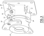
- FIG 3 shows in further detail an adjustable screw and nut arrangement, similar to that shown in Figure 1 . It can be seen in Figure 3 how rotation of the nut 16 with respect to the screw will secure the unthreaded pivot pin so that it cannot turn after adjustment is made. The nut is loosened when it is desired to turn the screw. By insertion of a hex key into the screw head, it is possible to turn the screw such that it moves in and out of the threaded lower pivot pin. This action will either lengthen or shorten the distance between the pivot pins provided within the respective bosses 18. Lengthening or shortening of the distance between the bosses 18 will, in turn, change the angle between the motor mounting flange 20 and the pump mounting flange 22 due to the resultant bending of the flexible hinge 24.
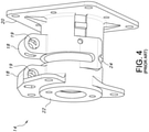
- Figure 4 shows a base 14 of the prior art without the adjustment mechanism. It can be appreciated how the base 14 shown in Figure 4 might be used in either of the two prior art embodiments described above, and can further be used with the present invention, as will be discussed in further detail below.
- the base 14 is made of an injection molded plastic and includes a motor mounting flange 20, the bosses 18 having apertures 19 formed therein, a pump mounting flange 22 and a living hinge 24 provided opposite the bosses.
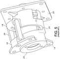
- Figure 5 shows a base 14 of the prior art, as described above, and further including a fixed link 26 for setting the distance between the bosses 18 thereby setting the angle between the motor flange 20 and the pump flange 22 with respect to the living hinge 24.
- the link 26 preferably includes a pair of injection molded complimentary segments, wherein each link segment includes an insertion pin portion 28 received within a matching sized pin receptacle portion 29 of the opposite link segment.
- the pin receptacle portions 29 of each link are sized to be interference fit within a correspondingly sized hole in a respective boss 18 of the base 14. Again, the length between the pin portion 28 and the pin receptacle portion 29 of each link 26 determines the angle between the pump and the motor.
- the present invention provides a fixed link arrangement with adjustability of the length between the apertures 19 of the respective bosses 18 of the base 14. This is achieved by providing an eccentric bushing 30, as shown in Figures 7 and 8 , received within one or both of the apertures 19 of the base bosses 18.
- the eccentric bushing 30 of the present invention includes a head portion 32 and a body portion 34 extending in coaxial relation with the head portion.
- the head portion 32 is preferably hexagonal shaped for purposes which will be described later.
- the body portion 34 is preferably cylindrically shaped and has an outer diameter sized to be interference fit within at least one of the through holes 19 provided in the bosses 18 of the base 14.
- the length of the body portion 34 is also preferably selected to match the length of the through hole 19 provided in the respective boss 18 of the base.
- a bore 36 Formed axially in the body portion 34 and the head portion 32 is a bore 36 extending the length of the bushing 30.
- the bore 36 has an axial center line 36' off set from the axial center line 34' of the body portion 34.
- the center line 36' of the bore 36 is not coaxial with the center line 34' of the body portion 34.
- the bushing 30 has an axial through hole 36 formed in an eccentric relation with the outer diameter of the body portion 34 so that rotation of the body portion about its axial center line 34' will cause the axial centerline 36' to revolve around the axial center line 34' of the body portion.
- the eccentric axial through hole 36 has an inner diameter sized to receive one of the pin receptacle portions 29 of the fixed link 26, (shown in Figure 6 ), in an interference or a press fit relationship.
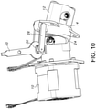
- FIGs 9 and 10 With the eccentric bushing 30 inserted in a through hole 19 of the boss 18 it can be seen how rotation of the bushing 30 with respect to the boss 18 will change the location of the inner bore 36 of the bushing with respect to the through hole 19 of the boss 18.
- the hexagonal shape of the head 32 of the bushing 30 also facilitates application of a wrench 40 to aid in rotation of the bushing 30.
- the head portion 32 of the bushing 30 is also preferably provided with a notch 38 so as to provide a visual indication of the maximum displacement of the through hole 36 with respect to the body portion 34.
- the notch 38 is preferably provided on the head portion 32 at a location that is furthest from the center line 36'of the inner bore 36.
- An improvement of the above described adjustment methods is to provide finer resolution of the angle change to such a degree where repeatable, sub-microliter flow adjustment can be made on demand while having the benefits of the fixed link concept.
- This improvement is realized by providing two eccentric bushings for both a fine adjustment and a coarse adjustment to meet variations in flow less than 1% of target flow for applications where sub-microliter variation is needed.
- maximizing the adjustable flow range of the fixed pump design increases the adaptably of a single pump design, allowing the same design to be used in different roles for the same customer application.
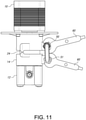
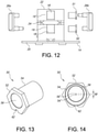
- FIGS. 11 and 12 an eccentric bushing is received in each of the apertures of the bosses of the flexible base to thereby provide even greater adjustability.
- the embodiment shown in FIGS. 11 and 12 is similar to that described above in that a conventional motor 10 is connected to a pump 12 via a flexible base 14. As described above, by varying the angle of the pump with respect to the motor, via the flexible hinge 24 of the base 14, the stroke of the piston is adjusted, thereby adjusting the volume of the fluid transferred between the inlet and the outlet.
- the base 14 includes a motor mounting flange 20, bosses 18 having apertures 19, 19' formed therein, a pump mounting flange 22 and a living hinge 24 provided opposite the bosses and between the flanges.
- a fixed link pair 26a, 26b is also provided for setting the distance between the bosses 18, as described above, to thereby set the angle between the motor flange 20 and the pump flange 22 with respect to the living hinge 24.
- two different eccentric bushings 50, 51 are provided for coarse and fine adjustment of the angle between the motor flange and the pump flange.
- a large eccentric bushing 50, for coarse adjustment is received in the aperture 19 of the boss 18 closer to the motor flange 20 and a smaller eccentric bushing 51, for fine adjustment, is received in the aperture 19' of the boss 18 located closer to the pump flange 22 of the base 14.
- each eccentric bushing 50, 51 includes a head portion 52, 53 and a body portion 54, 55 extending in coaxial relation with the head portion.
- the head portion 52, 53 is preferably hexagonal shaped for purposes which will be described later.
- the body portion 54, 55 is preferably cylindrically shaped and has an outer diameter sized to be interference fit within the through holes 19, 19' provided in the bosses 18 of the base 14.
- the length of the body portion 54, 55 is also preferably selected to match the length of the through hole 19, 19' provided in the respective boss 18 of the base.
- two differently sized through holes 19, 19' are preferably provided in their respective bosses 18.
- the through hole 19 for the large eccentric bushing 50 has a diameter of 8.73125 mm
- the diameter of the through hole 19' for the small eccentric bushing 51 has a diameter of 7.9375 mm.
- each bore 56, 57 Formed axially in the body portion 54, 55 and the head portion 52, 53 of each bushing 50, 51 is a bore 56, 57 extending the length of the bushing.
- Each bore 56, 57 has an axial center line 56', 57' off set from the axial center line 54', 55' of the respective body portion 54, 55.
- the center line 56', 57' of the respective bore 56, 57 is not coaxial with the center line 54', 55' of its respective body portion 54, 55.
- each bushing 50, 51 has an axial through hole 56, 57 formed in an eccentric relation with the outer diameter of its respective body portion 54, 55 so that rotation of the body portion about its axial center line 54', 55' will cause the axial centerline 56', 57' of the bore 56, 57 to revolve around the axial center line 54', 55' of the body portion.
- the offset 58 between the centerline 56' of the bore 56 and the centerline 54' of the body portion 54 of the larger eccentric bushing 50 is greater than the offset 59 between the centerline 57' of the bore 57 and the centerline 55' of the body portion 55 of the small eccentric bushing 51.
- a "coarse" angle adjustment e.g., angle adjustments greater than 0.5°
- a "fine” angle adjustment e.g., angle adjustments less than 0.5°
- the offset 58 between the centerline 56' of the bore 56 and the centerline 54' of the body portion 54 of the larger eccentric bushing 50 is preferably about .035", but can fall in the range between .381 mm and 1.27 mm.
- the offset 59 between the centerline 57' of the bore 57 and the centerline 55' of the body portion 55 of the small eccentric bushing 51 is preferably about .127 mm, but can fall in the range between 0 and .381 mm.
- each bushing 50, 51 has an inner diameter (e.g., 6.350 mm) sized to receive one of the pin receptacle portions 29 of the fixed link 26, (shown in FIGS. 6 and 12 ), in an interference or a press fit relationship.
- each bushing 50, 51 is also preferably provided with a notch 62, 63 so as to provide a visual indication of the maximum displacement of the through hole with respect to the body portion.
- the notch 62, 63 is preferably provided on the head portion at a location that is furthest from the center line of the inner bore.
- the large (coarse) bushing 50 is rotated for larger flow rate alterations (approximately 1-10% of the nominal flow), while the small (fine) bushing 51 is used for less than 1% flow adjustment.
- This dual design allows both a larger adjustment range than the single bushing design as well as more refinement across the possible output range. This is especially necessary when sub-microliter alterations are required, expanding the capability of the pump in "low-flow" applications. Also, this allows for the same pump design to be used in applications where multiple pumps are required with differing sub-microliter accuracy requirements are necessary.
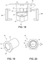
- two different eccentric bushings can be provided, wherein one bushing is nested within the other.
- a large eccentric bushing is received in one of the apertures of the bosses of the flexible base and a small eccentric bushing is received within the inner bore of the large eccentric bushing to thereby provide both fine and coarse adjustability.
- FIGS. 17 and 18 The embodiment shown in FIGS. 17 and 18 is similar to that described above and, therefore, the same reference numerals are used to identify identical components.
- the angle between a conventional motor 10 and a pump 12 is adjustable via a flexible base 14 having a motor mounting flange 20, bosses 18 having apertures 19" formed therein, a pump mounting flange 22 and a living hinge 24 provided opposite the bosses and between the flanges.
- a fixed link pair 26a, 26b is also provided for setting the distance between the bosses 18, as described above, to thereby set the angle between the motor flange 20 and the pump flange 22 with respect to the living hinge 24.
- two different eccentric bushings 70, 71 are provided for coarse and fine adjustment of the angle between the motor flange and the pump flange, wherein the small bushing 71 is received within the outer bushing 70 and the large eccentric bushing 70 can be received within either aperture 19"of the bosses.
- each eccentric bushing 70, 71 includes a head portion 72, 73 and a body portion 74, 75 extending in coaxial relation with the head portion.
- the head portion 72, 73 is preferably hexagonal shaped and the body portion 74, 75 is preferably cylindrically shaped, as described above.
- the outer diameter of the large eccentric bushing 70 is sized to be interference fit within either or both of the through holes 19" provided in the bosses 18 of the base 14.
- each bushing 70, 71 Formed axially in the body portion 74, 75 and the head portion 72, 73 of each bushing 70, 71 is a bore 76, 77 extending the length of the bushing.
- the bore 76 of the large bushing 70 is sized to receive the body portion 75 of the small bushing 71 and the bore 77 of the small bushing 71 is sized to receive sized to receive one of the pin receptacle portions 29 of the fixed link 26, (shown in FIGS. 6 , 12 and 18 ), in an interference or a press fit relationship.
- the body portion 74 of the large bushing 70 can have a diameter of 7.9375 mm and the inner bore 76 can have an inner diameter of 6.350 mm.
- the body portion 75 of the small bushing 71 can have a diameter of 6.350 mm and the inner bore 77 can have an inner diameter of 5.2832 mm.
- each bore 76, 77 has an axial center line 76', 77' off set from the axial center line 74', 75' of the respective body portion 74, 75.
- the center line 76', 77' of the respective bore 76, 77 is not coaxial with the center line 74', 75' of its respective body portion 54, 55.
- the offset 78 between the centerline 76' of the bore 76 and the centerline 74' of the body portion 74 of the larger eccentric bushing 70 is greater than the offset 79 between the centerline 77' of the bore 77 and the centerline 75' of the body portion 75 of the small eccentric bushing 71.
- rotation of the large bushing 70 about the body portion center line 74' will result in greater axial displacement of the bore center line 76', as compared with the small bushing 71.
- the offset 78 between the centerline 76' of the bore 76 and the centerline 74' of the body portion 74 of the larger eccentric bushing 70 is preferably about 8.89 mm, but can fall in the range between .381 mm and 1. 27 mm.
- the offset 79 between the centerline 77' of the bore 77 and the centerline 75' of the body portion 75 of the small eccentric bushing 71 is preferably about .005", but can fall in the range between 0 and .381 mm. It is also conceivable to provide the larger offset 78 (i.e., coarse adjustment) on the small bushing 71 and the smaller offset 79 (i.e., fine adjustment) on the large bushing 70.
- each bushing 70, 71 is also preferably provided with a notch 82, 83 so as to provide a visual indication of the maximum displacement of the through hole with respect to the body portion.
- the notch 82, 83 is preferably provided on the head portion at a location that is furthest from the center line of the inner bore.
Landscapes
- Engineering & Computer Science (AREA)
- Mechanical Engineering (AREA)
- General Engineering & Computer Science (AREA)
- Reciprocating Pumps (AREA)
- Details Of Reciprocating Pumps (AREA)
Claims (18)
- Un mécanisme pour le réglage d'un angle entre une pompe (12) et un moteur (10), la pompe (12) ayant un piston pouvant tourner autour d'un axe de rotation et pouvant effectuer une translation linéaire le long de l'axe de rotation, le mécanisme comprenant :une base (14) comprenant une bride de moteur (20) pour monter un moteur (10), une bride de pompe (22) opposée à ladite bride de moteur pour monter une pompe (12), une charnière (24) disposée entre ladite bride de moteur (20) et ladite bride de pompe (22) et une paire d'ouvertures espacées (19, 19') disposées à l'opposé de ladite charnière (24) ; etune liaison fixe (26) ayant une première partie de broche (28) reçue dans ladite première ouverture (19) de ladite base (14) et une seconde partie de broche (29) reçue dans ladite seconde ouverture (19') de ladite base (14), par lesquelles la liaison fixe raccorde les ouvertures (19, 19') de la base (14),caractérisé par :une première douille excentrique (50) ayant une partie de corps (54) reçue dans une première desdites ouvertures (19) de ladite base (14), ladite première douille excentrique (50) ayant un alésage interne (56) avec une ligne centrale axiale (56') décalée par rapport à une ligne centrale axiale (54') de ladite partie de corps (54) selon une première distance (58) ;une seconde douille excentrique (51) ayant une partie de corps (55) reçue dans l'un parmi une seconde desdites ouvertures (19') de ladite base (14) ou ledit alésage interne (56) de ladite première douille excentrique (50), ladite seconde douille excentrique (51) ayant un alésage interne (57) avec une ligne centrale axiale (57') décalée d'une ligne centrale axiale (55') de ladite partie de corps (55) selon une seconde distance (59), ladite seconde distance (58) étant différente de ladite première distance (59),dans lequel la rotation desdites douilles excentriques (50, 51) modifie la distance entre lesdites ouvertures (19, 19') de ladite base (14), modifiant ainsi un angle entre ladite bride de moteur (20) et ladite bride de pompe (22) autour de ladite charnière (24).
- Un mécanisme de réglage d'angle selon la revendication 1, dans lequel ladite seconde douille excentrique (51) est reçue dans ladite seconde ouverture (19') de ladite base (14), et dans lequel ladite partie de corps (55) de ladite seconde douille excentrique (51) a un diamètre différent d'un diamètre de la partie de corps (54) de ladite première douille excentrique (50).
- Un mécanisme de réglage d'angle selon la revendication 1, dans lequel l'une desdites première et seconde distances décalées (58) est dans la plage comprise entre 0,381 mm et 1,27 mm pour le réglage approximatif de la distance entre lesdites ouvertures (19, 19') et l'autre desdites première et seconde distances décalées (59) est dans la plage comprise entre 0 mm et 0,381 mm pour le réglage précis de la distance entre lesdites ouvertures (19, 19').
- Un mécanisme de réglage d'angle selon la revendication 1, dans lequel chacune desdites douilles excentriques (50, 51) comprend une partie de tête (52, 53) se terminant par une extrémité de ladite partie de corps (54, 55) pour faciliter la rotation de ladite douille excentrique.
- Un mécanisme de réglage d'angle selon la revendication 4, dans lequel ladite partie de tête (52, 53) comprend une encoche (62, 63) positionnée à une distance la plus éloignée de ladite ligne centrale (56', 57') dudit alésage interne (56, 57).
- Un mécanisme de réglage d'angle selon la revendication 1, dans lequel ladite charnière (24) de ladite base (14) est une charnière active formée de manière solidaire avec ladite base (14).
- Un mécanisme de réglage d'angle selon la revendication 1, dans lequel ladite liaison fixe (26) comprend une paire de segments complémentaires, chaque segment comprenant une partie de broche d'insertion (28) et une partie de broche de réceptacle (29), la partie de broche d'insertion de chaque segment étant reçue dans la partie de réceptacle de l'autre segment.
- Un ensemble de moteur et de pompe comprenant :une base (14) comprenant une bride de moteur (20), une bride de pompe (22) opposée à ladite bride de moteur, une charnière (24) disposée entre ladite bride de moteur (20) et ladite bride de pompe (22) et une paire d'ouvertures espacées (19, 19') disposée à l'opposé de ladite charnière (24) ;un moteur (10) monté sur ladite bride de moteur (20) de ladite base (14), ledit moteur (10) ayant un arbre pouvant tourner autour d'un axe de rotation ;une pompe (12) montée sur ladite bride de pompe (22) de ladite base (14), ladite pompe (12) ayant un piston pouvant tourner autour d'un axe de rotation et pouvant effectuer une translation linéaire le long de l'axe de rotation, ledit piston de pompe étant couplé audit arbre de moteur ; etune liaison fixe (26) ayant une première partie de broche reçue dans ladite première ouverture (19) de ladite base (14) et une seconde partie de broche reçue dans ladite seconde ouverture (19') de ladite base (14), par lesquelles la liaison fixe raccorde les ouvertures (19, 19') de la base (14),caractérisé par :une première douille excentrique (50) ayant une partie de corps (54) reçue dans une première desdites ouvertures de ladite base (14), ladite première douille excentrique (50) ayant un alésage interne (56) avec une ligne centrale axiale (56') décalée par rapport à une ligne centrale axiale (54') de ladite partie de corps (54) selon une première distance (58) ;une seconde douille excentrique (51) ayant une partie de corps (55) reçue dans l'un parmi une seconde desdites ouvertures (19') de ladite base (14) ou ledit alésage interne (56) de ladite première douille excentrique (50), ladite seconde douille excentrique (51) ayant un alésage interne (57) avec une ligne centrale axiale (57') décalée par rapport à une ligne centrale axiale (55') de ladite partie de corps (55) selon une seconde distance (59), ladite seconde distance (59) étant différente de ladite première distance (58),dans lequel la rotation desdites douilles excentriques (50, 51) modifie la distance entre lesdites ouvertures (19, 19') de ladite base (14), modifiant ainsi un angle entre ledit axe de rotation dudit arbre de moteur et ledit axe de rotation dudit piston de pompe autour de ladite charnière (24).
- Un ensemble de moteur et de pompe selon la revendication 8, dans lequel ladite seconde douille excentrique (51) est reçue dans ladite seconde ouverture (19') de ladite base (14), et dans lequel ladite partie de corps (55) de ladite seconde douille excentrique (51) a un diamètre différent d'un diamètre de la partie de corps (54) de ladite première douille excentrique (50).
- Un ensemble de moteur et de pompe selon la revendication 8, dans lequel l'une desdites première et seconde distances décalées (58) est dans la plage comprise entre 0,381 mm et 1,27 mm pour le réglage approximatif de la distance entre lesdites ouvertures (19, 19'), et l'autre desdites première et seconde distances décalées (59) est dans la plage comprise entre 0 mm et 0,381 mm pour le réglage précis de la distance entre lesdites ouvertures (19, 19').
- Un ensemble de moteur et de pompe selon la revendication 8, dans lequel chacune desdites douilles excentriques (50, 51) comprend une partie de tête (52, 53) se terminant par une extrémité de ladite partie de corps (54, 55) pour faciliter la rotation de ladite douille excentrique.
- Un ensemble de moteur et de pompe selon la revendication 11, dans lequel ladite partie de tête (52, 53) comprend une encoche (62, 63) positionnée à une distance la plus éloignée de ladite ligne centrale (56', 57') dudit alésage interne (56, 57).
- Un ensemble de moteur et de pompe selon la revendication 8, dans lequel ladite charnière (24) de ladite base est une charnière active formée de manière solidaire avec ladite base (14).
- Un ensemble de moteur et de pompe selon la revendication 8, dans lequel ladite liaison fixe (26) comprend une paire de segments complémentaires, chaque segment comprenant une partie de broche d'insertion (28) et une partie de broche de réceptacle (29), la partie de broche d'insertion de chaque segment étant reçue dans la partie de réceptacle de l'autre segment.
- Une méthode pour régler l'orientation angulaire entre un arbre de moteur d'un moteur (10) et un piston de pompe d'une pompe (12), le piston de pompe pouvant tourner autour d'un axe de rotation et pouvant effectuer une translation linéaire le long de l'axe de rotation, la méthode comprenant :prévoir une base (14) entre le moteur (10) et la pompe (12), la base (14) comprenant une bride de moteur (20) pour monter le moteur (10), une bride de pompe (22) opposée à la bride de moteur (20) pour monter la pompe (12), une charnière (24) disposée entre la bride de moteur (20) et la bride de pompe (22) et une paire d'ouvertures espacées (19, 19') disposée à l'opposé de la charnière (24) ;prévoir une liaison fixe (26) raccordant les ouvertures (19, 19') de la base (14) ; caractérisé par :faire tourner une première douille excentrique (50) ayant une partie de corps (54) reçue dans une première desdites ouvertures (19, 19') de ladite base (14), ladite première douille excentrique (50) ayant un alésage interne (56) avec une ligne centrale axiale (56') décalée par rapport à une ligne centrale axiale (54') de ladite partie de corps (54) selon une première distance (58) ; etfaire tourner une seconde douille excentrique (51) ayant une partie de corps (55) reçue dans l'un parmi une seconde desdites ouvertures (19, 19') de ladite base (14) ou ledit alésage interne (56) de ladite première douille excentrique (50), ladite seconde douille excentrique (51) ayant un alésage interne (57) avec une ligne centrale axiale (57') décalée par rapport à une ligne centrale axiale (55') de ladite partie de corps (55) selon une seconde distance (59), ladite seconde distance (59) étant différente de ladite première distance (58),moyennant quoi la rotation desdites douilles (50, 51) modifie une distance entre les ouvertures (19, 19') de ladite base (14), modifiant ainsi un angle entre ledit arbre de moteur et ledit piston de pompe autour de ladite charnière (24).
- Une méthode selon la revendication 15, dans laquelle ladite seconde douille excentrique (51) est reçue dans ladite seconde ouverture (19') de ladite base (14), et dans lequel ladite partie de corps (55) de ladite seconde douille excentrique (51) a un diamètre différent d'un diamètre de la partie de corps (54) de ladite première douille excentrique (50).
- Une méthode selon la revendication 15, dans laquelle l'une desdites première et seconde distances décalées (58) est dans la plage comprise entre 0,381 mm et 1,27 mm pour le réglage approximatif de la distance entre lesdites ouvertures (19, 19'), et l'autre desdites première et secondes distances décalées (59) est dans la plage comprise entre 0 mm et 0,381 mm pour le réglage précis de la distance entre lesdites ouvertures (19,19').
- Une méthode selon la revendication 15, dans lequel lesdites douilles excentriques (50, 51) sont entraînées en rotation à l'aide d'une clé (60) mise en prise avec une partie de tête hexagonale (52, 53) de chacune desdites douilles (50, 51).
Applications Claiming Priority (2)
| Application Number | Priority Date | Filing Date | Title |
|---|---|---|---|
| US15/830,592 US10935021B2 (en) | 2013-12-13 | 2017-12-04 | Mechanism for coarse and fine adjustment of flows in fixed displacement pump |
| PCT/US2018/063804 WO2019113036A1 (fr) | 2017-12-04 | 2018-12-04 | Mécanisme pour réglage approximatif et précis de flux dans une pompe volumétrique fixe |
Publications (3)
| Publication Number | Publication Date |
|---|---|
| EP3721092A1 EP3721092A1 (fr) | 2020-10-14 |
| EP3721092A4 EP3721092A4 (fr) | 2021-04-14 |
| EP3721092B1 true EP3721092B1 (fr) | 2022-03-16 |
Family
ID=66751719
Family Applications (1)
| Application Number | Title | Priority Date | Filing Date |
|---|---|---|---|
| EP18886990.3A Active EP3721092B1 (fr) | 2017-12-04 | 2018-12-04 | Mécanisme pour réglage approximatif et précis de flux dans une pompe volumétrique fixe |
Country Status (4)
| Country | Link |
|---|---|
| EP (1) | EP3721092B1 (fr) |
| DK (1) | DK3721092T3 (fr) |
| ES (1) | ES2911652T3 (fr) |
| WO (1) | WO2019113036A1 (fr) |
Family Cites Families (9)
| Publication number | Priority date | Publication date | Assignee | Title |
|---|---|---|---|---|
| US2027568A (en) * | 1928-10-11 | 1936-01-14 | Monarch Machine Tool Co | Lathe |
| GB1044326A (en) * | 1964-11-10 | 1966-09-28 | Duff Norton Co | Worm gear jack |
| US4420272A (en) * | 1982-09-27 | 1983-12-13 | Ingalls William E | Method and structure for bearing the eccentricity of a bushing bore |
| US5863187A (en) * | 1997-02-10 | 1999-01-26 | Ivek Corporation | Two position rotary reciprocating pump with liquid displacement flow adjustment |
| EA010848B1 (ru) * | 2004-10-20 | 2008-12-30 | Маркус Либхерр Интернациональ Аг | Гидростатическая аксиально-поршневая машина и применение такой машины |
| US20130199362A1 (en) * | 2012-02-02 | 2013-08-08 | Triumph Actuation Systems - Connecticut, LLC doing business as Triumph Aerospace Systems - Seattle | Bent axis variable delivery inline drive axial piston pump and/or motor |
| KR101322605B1 (ko) * | 2012-03-20 | 2013-10-29 | 한국기계연구원 | 상용차량에 장착되는 기계유압식 무단변속기 |
| JP6475259B2 (ja) * | 2013-12-13 | 2019-02-27 | フルード・メタリング・インコーポレイテッド | 定容積形ポンプにおける流量微調節装置 |
| DE102014211664A1 (de) * | 2014-06-18 | 2015-12-24 | Zf Friedrichshafen Ag | Anordnung mit mehreren Axialkolbenmaschinen |
-
2018
- 2018-12-04 ES ES18886990T patent/ES2911652T3/es active Active
- 2018-12-04 WO PCT/US2018/063804 patent/WO2019113036A1/fr not_active Ceased
- 2018-12-04 EP EP18886990.3A patent/EP3721092B1/fr active Active
- 2018-12-04 DK DK18886990.3T patent/DK3721092T3/da active
Also Published As
| Publication number | Publication date |
|---|---|
| EP3721092A4 (fr) | 2021-04-14 |
| EP3721092A1 (fr) | 2020-10-14 |
| WO2019113036A1 (fr) | 2019-06-13 |
| ES2911652T3 (es) | 2022-05-20 |
| DK3721092T3 (da) | 2022-06-13 |
Similar Documents
| Publication | Publication Date | Title |
|---|---|---|
| EP3080450B1 (fr) | Mécanisme pour réglage fin d'écoulement dans une pompe volumétrique fixe | |
| US6076799A (en) | Rotary valve actuator and linkage | |
| US10935021B2 (en) | Mechanism for coarse and fine adjustment of flows in fixed displacement pump | |
| US20250314247A1 (en) | Calibratable variable displacement pump | |
| US12398707B2 (en) | Mechanism for electronic adjustment of flows in fixed displacement pump | |
| EP3721092B1 (fr) | Mécanisme pour réglage approximatif et précis de flux dans une pompe volumétrique fixe | |
| EP2220529B1 (fr) | Dispositif et procédé permettant de régler la position d'un composant optique | |
| CA2102625C (fr) | Methode et appareil pour etalonner une pompe doseuse | |
| US5125803A (en) | Wobble plate type compressor with variable displacement mechanism | |
| US20080250921A1 (en) | Stroke adjustment mechanism for reciprocating pumps | |
| EP4212752B1 (fr) | Connecteur de transformateur différentiel variable rotatif (rvdt) | |
| CN112780515A (zh) | 柱塞泵 | |
| CN120792096A (zh) | 一种阀针位置调节机构及热流道系统 |
Legal Events
| Date | Code | Title | Description |
|---|---|---|---|
| STAA | Information on the status of an ep patent application or granted ep patent |
Free format text: STATUS: THE INTERNATIONAL PUBLICATION HAS BEEN MADE |
|
| PUAI | Public reference made under article 153(3) epc to a published international application that has entered the european phase |
Free format text: ORIGINAL CODE: 0009012 |
|
| STAA | Information on the status of an ep patent application or granted ep patent |
Free format text: STATUS: REQUEST FOR EXAMINATION WAS MADE |
|
| 17P | Request for examination filed |
Effective date: 20200526 |
|
| AK | Designated contracting states |
Kind code of ref document: A1 Designated state(s): AL AT BE BG CH CY CZ DE DK EE ES FI FR GB GR HR HU IE IS IT LI LT LU LV MC MK MT NL NO PL PT RO RS SE SI SK SM TR |
|
| AX | Request for extension of the european patent |
Extension state: BA ME |
|
| DAV | Request for validation of the european patent (deleted) | ||
| DAX | Request for extension of the european patent (deleted) | ||
| A4 | Supplementary search report drawn up and despatched |
Effective date: 20210315 |
|
| RIC1 | Information provided on ipc code assigned before grant |
Ipc: F04B 49/00 20060101AFI20210309BHEP Ipc: F04B 49/12 20060101ALI20210309BHEP Ipc: F04B 1/00 20200101ALI20210309BHEP Ipc: F04B 1/30 20200101ALI20210309BHEP Ipc: F04B 1/20 20200101ALI20210309BHEP Ipc: F04B 1/328 20200101ALI20210309BHEP |
|
| GRAP | Despatch of communication of intention to grant a patent |
Free format text: ORIGINAL CODE: EPIDOSNIGR1 |
|
| STAA | Information on the status of an ep patent application or granted ep patent |
Free format text: STATUS: GRANT OF PATENT IS INTENDED |
|
| INTG | Intention to grant announced |
Effective date: 20211022 |
|
| GRAS | Grant fee paid |
Free format text: ORIGINAL CODE: EPIDOSNIGR3 |
|
| GRAA | (expected) grant |
Free format text: ORIGINAL CODE: 0009210 |
|
| STAA | Information on the status of an ep patent application or granted ep patent |
Free format text: STATUS: THE PATENT HAS BEEN GRANTED |
|
| AK | Designated contracting states |
Kind code of ref document: B1 Designated state(s): AL AT BE BG CH CY CZ DE DK EE ES FI FR GB GR HR HU IE IS IT LI LT LU LV MC MK MT NL NO PL PT RO RS SE SI SK SM TR |
|
| REG | Reference to a national code |
Ref country code: GB Ref legal event code: FG4D |
|
| REG | Reference to a national code |
Ref country code: CH Ref legal event code: EP Ref country code: DE Ref legal event code: R096 Ref document number: 602018032492 Country of ref document: DE |
|
| REG | Reference to a national code |
Ref country code: IE Ref legal event code: FG4D |
|
| REG | Reference to a national code |
Ref country code: AT Ref legal event code: REF Ref document number: 1476057 Country of ref document: AT Kind code of ref document: T Effective date: 20220415 |
|
| REG | Reference to a national code |
Ref country code: SE Ref legal event code: TRGR |
|
| REG | Reference to a national code |
Ref country code: ES Ref legal event code: FG2A Ref document number: 2911652 Country of ref document: ES Kind code of ref document: T3 Effective date: 20220520 |
|
| REG | Reference to a national code |
Ref country code: DK Ref legal event code: T3 Effective date: 20220610 |
|
| REG | Reference to a national code |
Ref country code: LT Ref legal event code: MG9D |
|
| REG | Reference to a national code |
Ref country code: NL Ref legal event code: MP Effective date: 20220316 |
|
| PG25 | Lapsed in a contracting state [announced via postgrant information from national office to epo] |
Ref country code: RS Free format text: LAPSE BECAUSE OF FAILURE TO SUBMIT A TRANSLATION OF THE DESCRIPTION OR TO PAY THE FEE WITHIN THE PRESCRIBED TIME-LIMIT Effective date: 20220316 Ref country code: NO Free format text: LAPSE BECAUSE OF FAILURE TO SUBMIT A TRANSLATION OF THE DESCRIPTION OR TO PAY THE FEE WITHIN THE PRESCRIBED TIME-LIMIT Effective date: 20220616 Ref country code: LT Free format text: LAPSE BECAUSE OF FAILURE TO SUBMIT A TRANSLATION OF THE DESCRIPTION OR TO PAY THE FEE WITHIN THE PRESCRIBED TIME-LIMIT Effective date: 20220316 Ref country code: HR Free format text: LAPSE BECAUSE OF FAILURE TO SUBMIT A TRANSLATION OF THE DESCRIPTION OR TO PAY THE FEE WITHIN THE PRESCRIBED TIME-LIMIT Effective date: 20220316 Ref country code: BG Free format text: LAPSE BECAUSE OF FAILURE TO SUBMIT A TRANSLATION OF THE DESCRIPTION OR TO PAY THE FEE WITHIN THE PRESCRIBED TIME-LIMIT Effective date: 20220616 |
|
| REG | Reference to a national code |
Ref country code: AT Ref legal event code: MK05 Ref document number: 1476057 Country of ref document: AT Kind code of ref document: T Effective date: 20220316 |
|
| PG25 | Lapsed in a contracting state [announced via postgrant information from national office to epo] |
Ref country code: LV Free format text: LAPSE BECAUSE OF FAILURE TO SUBMIT A TRANSLATION OF THE DESCRIPTION OR TO PAY THE FEE WITHIN THE PRESCRIBED TIME-LIMIT Effective date: 20220316 Ref country code: GR Free format text: LAPSE BECAUSE OF FAILURE TO SUBMIT A TRANSLATION OF THE DESCRIPTION OR TO PAY THE FEE WITHIN THE PRESCRIBED TIME-LIMIT Effective date: 20220617 Ref country code: FI Free format text: LAPSE BECAUSE OF FAILURE TO SUBMIT A TRANSLATION OF THE DESCRIPTION OR TO PAY THE FEE WITHIN THE PRESCRIBED TIME-LIMIT Effective date: 20220316 |
|
| PG25 | Lapsed in a contracting state [announced via postgrant information from national office to epo] |
Ref country code: NL Free format text: LAPSE BECAUSE OF FAILURE TO SUBMIT A TRANSLATION OF THE DESCRIPTION OR TO PAY THE FEE WITHIN THE PRESCRIBED TIME-LIMIT Effective date: 20220316 |
|
| PG25 | Lapsed in a contracting state [announced via postgrant information from national office to epo] |
Ref country code: SM Free format text: LAPSE BECAUSE OF FAILURE TO SUBMIT A TRANSLATION OF THE DESCRIPTION OR TO PAY THE FEE WITHIN THE PRESCRIBED TIME-LIMIT Effective date: 20220316 Ref country code: SK Free format text: LAPSE BECAUSE OF FAILURE TO SUBMIT A TRANSLATION OF THE DESCRIPTION OR TO PAY THE FEE WITHIN THE PRESCRIBED TIME-LIMIT Effective date: 20220316 Ref country code: RO Free format text: LAPSE BECAUSE OF FAILURE TO SUBMIT A TRANSLATION OF THE DESCRIPTION OR TO PAY THE FEE WITHIN THE PRESCRIBED TIME-LIMIT Effective date: 20220316 Ref country code: PT Free format text: LAPSE BECAUSE OF FAILURE TO SUBMIT A TRANSLATION OF THE DESCRIPTION OR TO PAY THE FEE WITHIN THE PRESCRIBED TIME-LIMIT Effective date: 20220718 Ref country code: EE Free format text: LAPSE BECAUSE OF FAILURE TO SUBMIT A TRANSLATION OF THE DESCRIPTION OR TO PAY THE FEE WITHIN THE PRESCRIBED TIME-LIMIT Effective date: 20220316 Ref country code: CZ Free format text: LAPSE BECAUSE OF FAILURE TO SUBMIT A TRANSLATION OF THE DESCRIPTION OR TO PAY THE FEE WITHIN THE PRESCRIBED TIME-LIMIT Effective date: 20220316 Ref country code: AT Free format text: LAPSE BECAUSE OF FAILURE TO SUBMIT A TRANSLATION OF THE DESCRIPTION OR TO PAY THE FEE WITHIN THE PRESCRIBED TIME-LIMIT Effective date: 20220316 |
|
| PG25 | Lapsed in a contracting state [announced via postgrant information from national office to epo] |
Ref country code: PL Free format text: LAPSE BECAUSE OF FAILURE TO SUBMIT A TRANSLATION OF THE DESCRIPTION OR TO PAY THE FEE WITHIN THE PRESCRIBED TIME-LIMIT Effective date: 20220316 Ref country code: IS Free format text: LAPSE BECAUSE OF FAILURE TO SUBMIT A TRANSLATION OF THE DESCRIPTION OR TO PAY THE FEE WITHIN THE PRESCRIBED TIME-LIMIT Effective date: 20220716 Ref country code: AL Free format text: LAPSE BECAUSE OF FAILURE TO SUBMIT A TRANSLATION OF THE DESCRIPTION OR TO PAY THE FEE WITHIN THE PRESCRIBED TIME-LIMIT Effective date: 20220316 |
|
| REG | Reference to a national code |
Ref country code: DE Ref legal event code: R097 Ref document number: 602018032492 Country of ref document: DE |
|
| PLBE | No opposition filed within time limit |
Free format text: ORIGINAL CODE: 0009261 |
|
| STAA | Information on the status of an ep patent application or granted ep patent |
Free format text: STATUS: NO OPPOSITION FILED WITHIN TIME LIMIT |
|
| 26N | No opposition filed |
Effective date: 20221219 |
|
| PG25 | Lapsed in a contracting state [announced via postgrant information from national office to epo] |
Ref country code: SI Free format text: LAPSE BECAUSE OF FAILURE TO SUBMIT A TRANSLATION OF THE DESCRIPTION OR TO PAY THE FEE WITHIN THE PRESCRIBED TIME-LIMIT Effective date: 20220316 |
|
| P01 | Opt-out of the competence of the unified patent court (upc) registered |
Effective date: 20230527 |
|
| REG | Reference to a national code |
Ref country code: BE Ref legal event code: MM Effective date: 20221231 |
|
| PG25 | Lapsed in a contracting state [announced via postgrant information from national office to epo] |
Ref country code: LU Free format text: LAPSE BECAUSE OF NON-PAYMENT OF DUE FEES Effective date: 20221204 |
|
| PG25 | Lapsed in a contracting state [announced via postgrant information from national office to epo] |
Ref country code: BE Free format text: LAPSE BECAUSE OF NON-PAYMENT OF DUE FEES Effective date: 20221231 |
|
| PG25 | Lapsed in a contracting state [announced via postgrant information from national office to epo] |
Ref country code: CY Free format text: LAPSE BECAUSE OF FAILURE TO SUBMIT A TRANSLATION OF THE DESCRIPTION OR TO PAY THE FEE WITHIN THE PRESCRIBED TIME-LIMIT Effective date: 20220316 |
|
| PG25 | Lapsed in a contracting state [announced via postgrant information from national office to epo] |
Ref country code: MK Free format text: LAPSE BECAUSE OF FAILURE TO SUBMIT A TRANSLATION OF THE DESCRIPTION OR TO PAY THE FEE WITHIN THE PRESCRIBED TIME-LIMIT Effective date: 20220316 Ref country code: HU Free format text: LAPSE BECAUSE OF FAILURE TO SUBMIT A TRANSLATION OF THE DESCRIPTION OR TO PAY THE FEE WITHIN THE PRESCRIBED TIME-LIMIT; INVALID AB INITIO Effective date: 20181204 |
|
| PG25 | Lapsed in a contracting state [announced via postgrant information from national office to epo] |
Ref country code: MC Free format text: LAPSE BECAUSE OF FAILURE TO SUBMIT A TRANSLATION OF THE DESCRIPTION OR TO PAY THE FEE WITHIN THE PRESCRIBED TIME-LIMIT Effective date: 20220316 |
|
| PG25 | Lapsed in a contracting state [announced via postgrant information from national office to epo] |
Ref country code: TR Free format text: LAPSE BECAUSE OF FAILURE TO SUBMIT A TRANSLATION OF THE DESCRIPTION OR TO PAY THE FEE WITHIN THE PRESCRIBED TIME-LIMIT Effective date: 20220316 Ref country code: MC Free format text: LAPSE BECAUSE OF FAILURE TO SUBMIT A TRANSLATION OF THE DESCRIPTION OR TO PAY THE FEE WITHIN THE PRESCRIBED TIME-LIMIT Effective date: 20220316 |
|
| PG25 | Lapsed in a contracting state [announced via postgrant information from national office to epo] |
Ref country code: MT Free format text: LAPSE BECAUSE OF FAILURE TO SUBMIT A TRANSLATION OF THE DESCRIPTION OR TO PAY THE FEE WITHIN THE PRESCRIBED TIME-LIMIT Effective date: 20220316 |
|
| REG | Reference to a national code |
Ref country code: CH Ref legal event code: U11 Free format text: ST27 STATUS EVENT CODE: U-0-0-U10-U11 (AS PROVIDED BY THE NATIONAL OFFICE) Effective date: 20260101 |
|
| PGFP | Annual fee paid to national office [announced via postgrant information from national office to epo] |
Ref country code: GB Payment date: 20251229 Year of fee payment: 8 |
|
| PGFP | Annual fee paid to national office [announced via postgrant information from national office to epo] |
Ref country code: DK Payment date: 20251217 Year of fee payment: 8 |
|
| PGFP | Annual fee paid to national office [announced via postgrant information from national office to epo] |
Ref country code: FR Payment date: 20251222 Year of fee payment: 8 |
|
| PGFP | Annual fee paid to national office [announced via postgrant information from national office to epo] |
Ref country code: SE Payment date: 20251217 Year of fee payment: 8 |
|
| PGFP | Annual fee paid to national office [announced via postgrant information from national office to epo] |
Ref country code: IE Payment date: 20251218 Year of fee payment: 8 |
|
| PGFP | Annual fee paid to national office [announced via postgrant information from national office to epo] |
Ref country code: ES Payment date: 20260119 Year of fee payment: 8 |
|
| PGFP | Annual fee paid to national office [announced via postgrant information from national office to epo] |
Ref country code: DE Payment date: 20251222 Year of fee payment: 8 |
|
| PGFP | Annual fee paid to national office [announced via postgrant information from national office to epo] |
Ref country code: IT Payment date: 20251231 Year of fee payment: 8 |
|
| PGFP | Annual fee paid to national office [announced via postgrant information from national office to epo] |
Ref country code: CH Payment date: 20260101 Year of fee payment: 8 |