EP3721135B1 - Signalvorrichtung für ein kraftfahrzeug, umfassend einen oder mehrere homogen beleuchtete lichtschirme - Google Patents
Signalvorrichtung für ein kraftfahrzeug, umfassend einen oder mehrere homogen beleuchtete lichtschirme Download PDFInfo
- Publication number
- EP3721135B1 EP3721135B1 EP18830912.4A EP18830912A EP3721135B1 EP 3721135 B1 EP3721135 B1 EP 3721135B1 EP 18830912 A EP18830912 A EP 18830912A EP 3721135 B1 EP3721135 B1 EP 3721135B1
- Authority
- EP
- European Patent Office
- Prior art keywords
- screen
- light
- light source
- face
- signalling device
- Prior art date
- Legal status (The legal status is an assumption and is not a legal conclusion. Google has not performed a legal analysis and makes no representation as to the accuracy of the status listed.)
- Active
Links
Images




Classifications
-
- F—MECHANICAL ENGINEERING; LIGHTING; HEATING; WEAPONS; BLASTING
- F21—LIGHTING
- F21S—NON-PORTABLE LIGHTING DEVICES; SYSTEMS THEREOF; VEHICLE LIGHTING DEVICES SPECIALLY ADAPTED FOR VEHICLE EXTERIORS
- F21S43/00—Signalling devices specially adapted for vehicle exteriors, e.g. brake lamps, direction indicator lights or reversing lights
- F21S43/20—Signalling devices specially adapted for vehicle exteriors, e.g. brake lamps, direction indicator lights or reversing lights characterised by refractors, transparent cover plates, light guides or filters
- F21S43/27—Attachment thereof
-
- F—MECHANICAL ENGINEERING; LIGHTING; HEATING; WEAPONS; BLASTING
- F21—LIGHTING
- F21S—NON-PORTABLE LIGHTING DEVICES; SYSTEMS THEREOF; VEHICLE LIGHTING DEVICES SPECIALLY ADAPTED FOR VEHICLE EXTERIORS
- F21S43/00—Signalling devices specially adapted for vehicle exteriors, e.g. brake lamps, direction indicator lights or reversing lights
- F21S43/10—Signalling devices specially adapted for vehicle exteriors, e.g. brake lamps, direction indicator lights or reversing lights characterised by the light source
- F21S43/13—Signalling devices specially adapted for vehicle exteriors, e.g. brake lamps, direction indicator lights or reversing lights characterised by the light source characterised by the type of light source
- F21S43/14—Light emitting diodes [LED]
-
- F—MECHANICAL ENGINEERING; LIGHTING; HEATING; WEAPONS; BLASTING
- F21—LIGHTING
- F21S—NON-PORTABLE LIGHTING DEVICES; SYSTEMS THEREOF; VEHICLE LIGHTING DEVICES SPECIALLY ADAPTED FOR VEHICLE EXTERIORS
- F21S43/00—Signalling devices specially adapted for vehicle exteriors, e.g. brake lamps, direction indicator lights or reversing lights
- F21S43/20—Signalling devices specially adapted for vehicle exteriors, e.g. brake lamps, direction indicator lights or reversing lights characterised by refractors, transparent cover plates, light guides or filters
- F21S43/26—Refractors, transparent cover plates, light guides or filters not provided in groups F21S43/235 - F21S43/255
-
- F—MECHANICAL ENGINEERING; LIGHTING; HEATING; WEAPONS; BLASTING
- F21—LIGHTING
- F21S—NON-PORTABLE LIGHTING DEVICES; SYSTEMS THEREOF; VEHICLE LIGHTING DEVICES SPECIALLY ADAPTED FOR VEHICLE EXTERIORS
- F21S43/00—Signalling devices specially adapted for vehicle exteriors, e.g. brake lamps, direction indicator lights or reversing lights
- F21S43/30—Signalling devices specially adapted for vehicle exteriors, e.g. brake lamps, direction indicator lights or reversing lights characterised by reflectors
- F21S43/33—Signalling devices specially adapted for vehicle exteriors, e.g. brake lamps, direction indicator lights or reversing lights characterised by reflectors characterised by their material, surface treatment or coatings
-
- F—MECHANICAL ENGINEERING; LIGHTING; HEATING; WEAPONS; BLASTING
- F21—LIGHTING
- F21S—NON-PORTABLE LIGHTING DEVICES; SYSTEMS THEREOF; VEHICLE LIGHTING DEVICES SPECIALLY ADAPTED FOR VEHICLE EXTERIORS
- F21S43/00—Signalling devices specially adapted for vehicle exteriors, e.g. brake lamps, direction indicator lights or reversing lights
- F21S43/40—Signalling devices specially adapted for vehicle exteriors, e.g. brake lamps, direction indicator lights or reversing lights characterised by the combination of reflectors and refractors
Definitions
- the present invention relates to a signaling device for a motor vehicle, comprising one or more homogeneously illuminated light screens.
- An organic light-emitting diode or EO diode consists of a substrate, two electrodes intended to inject charges of opposite sign and an organic layer interposed between the electrodes.
- the EO diode emits light when the electrodes pass sufficient electrical current through the organic layer. At least one electrode must be transparent for the light to diffuse outside.
- the electrodes are supplied with current via electrical connectors arranged on the periphery of the EO diode.
- the electrical connectors are usually hidden behind a fixing frame of a certain thickness and surrounding the EO diode. The position of the electrical connectors or the The presence of the fixing frame makes it difficult to arrange them to form a single, continuous luminous surface.
- the homogeneous lighting surfaces obtained from EO diodes are generally limited to the dimensions of the EO diode itself.
- EO diodes currently used in the automotive sector are limited to a few square centimeters. It is therefore not possible to form homogeneous luminous surfaces of large dimensions and at low cost.
- the invention aims to resolve these defects by proposing a signaling device for a motor vehicle comprising at least one luminous screen, homogeneously illuminated, of larger dimensions, more reliable and less expensive.
- the signaling device therefore comprises a means of obscuring a peripheral part of the light beam emitted by the light source, so that only the part of the screen illuminated by the center of the light beam is visible by an observer.
- the concealment means does not deflect and/or does not obscure a central part of the light beam homogeneously illuminating the second face of the screen.
- the central part of the light beam is surrounded by the peripheral part mentioned above.
- homogeneous we mean a luminous surface whose appearance appears uniform to an observer.
- the concealment means therefore makes it possible to hide the parts of the screen perceived by an observer as being of different light intensity relative to the center of the screen.
- a screen can be illuminated homogeneously from a lower cost light source compared to an organic light-emitting diode or EO diode.
- the light source may be a light source commonly used in the automotive field such as a filament bulb.
- the source of light is a light-emitting diode.
- the light source is oriented so that its light beam directly illuminates the first side of the screen. This embodiment makes it possible to limit the bulk of the signaling device and facilitate its integration in or on a motor vehicle.
- the invention thus offers a more reliable and more economical alternative to the use of EO diodes in signaling devices for motor vehicles.
- the dimensions of the homogeneously illuminated screen are not limited by the manufacturing process of the light source, as is currently the case for EO diodes. Indeed, we can easily modify the dimensions of the screen by adjusting for example the opening angle of the light beam emitted by the light source and/or the distance between the screen and the light source.
- the invention also allows the production of light screens of very varied dimensions, in particular of dimensions greater than EO diodes.
- the light source is placed behind the screen, so that its electrical connectors do not clutter the periphery of the screen as for the EO diodes and can be hidden behind said screen.
- the concealment means comprises an opaque film surrounding the part of the screen illuminated by the light beam emitted by the light source.
- opaque film we mean the fact that the film obscures the light beam emitted by the light source.
- the opaque film thus makes it possible to hide from an observer the areas of the second side of the screen which would be perceived as non-homogeneous in intensity.
- the opaque film can also mask a part of the screen, illuminated homogeneously, so as to define a light pattern such as a pictogram, a letter or a number.
- the opaque film is placed in front of the second face of the screen.
- the opaque film is placed in front of the first face of the screen.
- the opaque film comprises an ink covering part of the second face of the screen.
- the signaling device may comprise several opaque films which overlap and move, so as to form light patterns of different shapes at the level of the screen when the opaque films are shifted.
- the concealment means comprises a sheath present between the light source and the screen, the sheath being arranged so as to surround the light beam emitted by the light source so that only a central part of the beam bright directly illuminates the screen.
- the sheath is configured so that the most intense part of the light beam directly illuminates the first face of the screen.
- the sheath is positioned so as to intercept and/or deflect the peripheral part of the light beam.
- the invention can also make it possible to avoid the use of an opaque film as described above, while obtaining a similar result, in particular in order to reduce the bulk of the signaling device.
- the invention makes it possible to illuminate a screen homogeneously for an observer, by using a light source of lower light intensity compared to the state of the art.
- a light source of lower light intensity the size of the light source in the signaling device is significantly reduced, in particular the size of the devices making it possible to dissipate the heat produced by the light source.
- the invention also makes it possible to reduce the size of the light source in the signaling device.
- the internal face of the sheath is light in color, preferably white in color.
- This embodiment advantageously allows the sheath to reflect the peripheral part of the light beam towards the screen, in particular in order to increase its light intensity.
- the internal face of the sheath comprises means for diffusing the light beam.
- This embodiment advantageously makes it possible to homogenize the intensity of the beam reflected by the sheath.
- the sheath comprises a distal end, facing the first face of the screen, delimiting a first opening, and the contour of the first opening is hidden behind a film opaque, preferably the opaque film is placed in front of the second face of the screen.
- the contour of the first opening delimits an oval or polygonal shape.
- the opaque film delimits a shape identical or similar to the contour of the first opening.
- the sheath comprises a proximal end facing the light source and the proximal end defines an oval contour around the light beam.
- the proximal end forms an optical reflector around the light beam.
- the screen is translucent.
- This embodiment advantageously makes it possible to attenuate variations in light intensity at the level of the second face of the screen.
- the diffusion coefficient of the screen decreases when one moves away from the center of the light beam.
- the diffusion coefficient of the screen varies so as to substantially compensate for the variation in light intensity at the level of the second face of the screen when the screen is illuminated by the light beam. This embodiment advantageously makes it possible to attenuate variations in light intensity at the level of the second face of the screen.
- the signaling device comprises at least two adjacent screens described above, and a control unit making it possible to independently turn on or turn off each light source independently.
- the control unit can be configured to simultaneously light up several adjacent screens in order to form a larger luminous screen and/or successively light up several screens so as to create an animation.
- the invention allows the use of a light source of lower light intensity compared to the state of the art, in order to backlight a screen whose light intensity is perceived homogeneously by an observer.
- an overall light screen of larger dimensions can be formed.
- the depth of the light device then does not vary as a function of the dimensions of the overall light screen.
- the depth of the light device is identical or substantially identical for one or more adjacent screens.
- the invention advantageously allows the production of global light screens of larger surfaces, perceived with homogeneous light intensity by an observer, for a much smaller footprint in depth compared to the state of the art.
- the size of the light source in the signaling device is significantly reduced, in particular the size of the devices making it possible to dissipate the heat produced by the light source.
- this embodiment also makes it possible to reduce the size of the light source in the signaling device.
- the concealment means comprises a sheath arranged between the light source and the screen, each sheath being configured to surround the light beam emitted by each light source of so that only a central part of the light beam directly illuminates the screen and in that the sheath is translucent.
- This embodiment makes it possible to create a gradient of light intensity around a lit screen, while preserving the homogeneous appearance of the screen in intensity.
- the adjacent screens have their sheath in contact in order to promote the diffusion of the light emitted by the lit screen in the unlit and adjacent screens.
- the signaling device can display gradients of light around one or more lit screens whose intensity is homogeneous.
- the concealment means comprises a sheath arranged between the light source and the screen, each sheath being configured to surround the light beam emitted by each light source so that only a central part of the light beam directly illuminates the screen, and in that the internal face of each sheath is dark in color, preferably black in color.
- this embodiment allows the light from each screen to be confined so that the signaling device can display sharper patterns.
- the screen placed in front of the light source comprises at least two distinct superimposed layers: a translucent layer and a metallized layer at least partially covering the translucent layer.
- the metallized layer is in contact with the second face of the translucent screen and configured to reflect ambient external light.
- the metallized layer completely covers the translucent layer so that the elements facing the first face of the translucent layer are not visible through the screen when the light source is turned off.
- the metallized layer is made from one of the following materials: chrome, stainless steel, bronze, aluminum or tungsten.
- the metallized layer may be colored.
- the translucent layer is colored non-uniformly, with one or more distinct colors in order to form patterns visible to an observer facing the signaling device.
- the translucent layer comprises passages passing through said layer, the dimensions of which are configured to form zones illuminated by the light source more intensely at the level of the metallized layer.
- This embodiment aims to allow patterns to be formed on the surface of the metallized layer when the light source is turned on.
- the smallest dimension of a passage is between 1 mm and 5 cm, preferably between 1 cm and 3 cm.
- the creation of these passages can make it possible to meet both aesthetic wishes and regulatory constraints.
- the translucent layer is screen printed on at least one of its faces, so as to locally modify its transmittance when illuminated by a light source.
- the signaling device comprises a transparent layer placed in front of the metallized layer, so that the metallized layer is present between the translucent layer and the transparent layer.
- the transparent layer is in contact with the metallized layer.
- This embodiment is particularly advantageous when it is desired for the screen to form an outer shell or an indicator light for a traffic light.
- the transparent layer is colored, preferably red.
- the invention also relates to a motor vehicle comprising a signaling device as described above.
- the invention aims to propose a signaling device for a motor vehicle comprising at least one luminous screen, illuminated homogeneously, of larger dimensions, more reliable and less expensive compared to the state of the art.
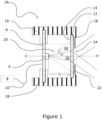
- FIG. 1 presents a first embodiment of a signaling device 2A falling outside the scope of the invention.
- This signaling device comprises a light source 4 mounted on a support 6.
- the support comprises conductive tracks not shown, connecting the light source to a control unit 8 via conductive wires 10.
- the control unit 8 is configured to control the operation of the light source 4, that is to say turn it on or off.
- the light source is a light-emitting diode.
- the light source 4 is positioned opposite a screen 12 via a frame holding the support 6 to the screen 12, so as to directly illuminate a first face 14 of the screen.
- the screen is chosen so as to transmit the light emitted by the light source 4 to a second face 16 opposite the first face. More precisely, the frame 18 maintains the light source at a distance D from the first face of the screen, so that its light beam 20 is circumscribed to the first face 14 of the screen.
- the screen is flat.
- the light beam 20 emitted by the light source decreases in intensity as we approach its periphery.
- the light beam 20 decreases in intensity as we move away from its optical axis (OO'), the intensity of the light beam being maximum at its center.
- the control unit 8 turns on the light source 4
- the first face 14 is illuminated non-uniformly by the light beam 20.
- the second face 16 of the screen appears brighter at the level of the optical axis (OO') of the light source.
- the invention aims to overcome this defect, by proposing to position an opaque film 22 in front of the second face 16 of the screen, masking the areas of the second face appearing of less intensity when illuminated by the light beam 20.
- the opaque film 22 includes a passage 24 whose shape and dimensions are adapted so as to leave visible only an area of the second face, appearing to an observer to be homogeneously illuminated by the light beam 20.
- a surface is perceived as uniformly or homogeneously illuminated, when the difference in light intensity between the brightest area of the screen and another area of the screen, divided by the intensity value of the brightest area of the screen is equal to or does not exceed 60%, or is equal to or less than 40%, or is equal to or less than 20%.
- the opaque film 22 is sized and placed in front of the second face 16 of the screen, so as to allow only a central part 26 of the light beam 20 to pass, and mask another so-called peripheral part whose intensity, at the level of the second face of the screen, is equal to or less than 80% relative to the center of the light beam 20, preferably equal to or less than 60% relative to the center of the light beam 20.
- the central part 26 of the light beam defined by the angle ⁇ on the figure 1
- the peripheral part 28 of the light beam surrounding the central part 26, defined by the angle ⁇ on the figure 1 is stopped by the opaque film 22.
- the passage 24 provided through the opaque film 22 can delimit one or more pictograms and/or letters and/or numbers.
- FIG. 2 now illustrates a second embodiment of a 2B signaling device according to the invention.
- the invention differs from the previous embodiment in that the opaque film 22 is no longer present.
- the opaque film 22 is replaced by a sheath 30 positioned between the light source 4 and the first face 14 of the screen 12. More precisely, the sheath 30 is arranged around the light beam 20.
- the sheath comprises a proximal end 32 in opposite the light source 4 and a distal end 34 in contact with the screen 12.
- the distal end 34 is configured to intercept the peripheral part 28 of the light beam defined above, so that only the central part 26 of the light beam directly illuminates the first face 14 of the screen.
- the distal end 34 is configured to absorb the light emitted by the light source 4 in order to preserve, for an observer, the impression of homogeneity of the light diffusing through the second face 16 of the screen 12.
- the invention makes it possible to obtain substantially the same result as the previous embodiment, while avoiding the use of an opaque film placed in front of the screen.
- the invention is therefore advantageous when it is desired to preserve the appearance of the second face and/or reduce the bulk of the signaling device.
- the distal end 34 can be configured to reflect, in the direction of the screen 12, the light emitted by the light source 4. This embodiment advantageously makes it possible to increase the light intensity of the screen 12.
- the surface of the distal end 34 is configured to diffuse the light in a diffuse manner, in order to increase the impression of homogeneous lighting of the screen 12 when it is backlit by the light source 4.
- the internal face of the sheath 30 is light or substantially light in color.
- FIG. 3 illustrates a third embodiment of a 2C signaling device according to the invention.
- several light sources 4A, 4B and 4C are placed on the same support 6.
- the support comprises conductive tracks not shown, connecting each light source to a control unit 8 via conductive wires 10.
- the control unit 8 is configured to control the operation of each light source 4A, 4B and 4C, simultaneously or alternately.
- the light sources 4A, 4B and 4C are positioned opposite a screen 12 via a frame 18 holding the support to the screen 12, so as to illuminate a first face 14 of the 'screen.
- the screen is chosen so as to transmit the light emitted by the light sources 4 to a second face 16 opposite the first face.
- Each light beam 20 emitted by a light source is surrounded by a dedicated sheath 30. As described above, each sheath is configured to intercept the peripheral part 28 of the light beam, so that only the central part 26 of the light beam directly illuminates the first face 14 of the screen.
- the sheaths 30 are opaque to the light beams 20 and configured to allow the central parts 26 of the light beams to cross before or at the level of the second face 16 of the screen, so that said face is illuminated so uniform.
- the dimensions of the signaling screen can be easily increased and exceed the largest dimensions of current EO diodes.
- the invention therefore makes it possible to obtain large-sized signaling screens of homogeneous intensity for a low manufacturing cost.
- the signaling device 2C comprises three light sources 4A, 4B and 4C, so that the display device can display three pixels 17A, 17B, X17C bright at the second side 16 of the screen.
- the invention is not limited to this number of light sources so that the light screen can display a greater number of pixels.
- control unit 8 can be configured to turn on each light source 4A, 4B and 4C alternately or in a complementary manner, in order to form pixelated images or information, the dimensions and shapes of which can be modified. at will.
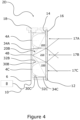
- FIG. 4 illustrates a fourth embodiment of a 2D signaling device outside the scope of the invention.
- This device differs from the third mode in that the sheaths 30 are made of a material allowing the passage of part of the light emitted by the light sources 4A, 4B and 4C into the adjacent sheaths.
- This embodiment makes it possible to display at the second face 16 of the screen one or more light pixels 13 of the same intensity, surrounded by a light halo whose intensity decreases when one moves away from said pixel(s). luminous.
- the screen 12 displays a light pixel 17B homogeneous in intensity, illuminated by the central part 26B of the light beam 20B emitted by the light source 4B, and two light pixels 17A and 17C of non-homogeneous intensity when the light sources 4A and 4B are not lit.
- FIG. 5 illustrates a fifth embodiment of a 2E signaling device according to the invention.
- This signaling device is a hybrid mode between the first and third embodiments described above.
- an opaque film 22 is placed in front of the second face 16 of the screen 12 of the signaling device 2C so as to conceal the contour of each opening delimited by the distal end 34A, 34B and 34C of a sheath.
- the opaque film 22 here comprises several passages, each passage forming a pattern of different shape and dimensions. The invention thus allows the production of a large luminous screen, formed of different luminous pixels 17A, 17B, 17C and 17C', to display different luminous information simultaneously or alternately.
- FIG. 6 illustrates a sixth embodiment of a 2F signaling device according to the invention.
- This embodiment is similar to the third embodiment described above, with the difference that the screen 12 is curved. So that the screen can be illuminated homogeneously by the light sources 4A, 4B and 4C, these are placed on separate supports 36. Each support is connected to the control unit 8 via a plate 38. The plate 38 also makes it possible to hold each support to the chassis 18, so that each light source 4A, 4B and 4C is substantially at the same distance than the screen 12.
- the light source is preferably a light-emitting diode in order to limit the depth of the signaling devices.
- Light-emitting diodes can be the same or different.
- each light source may comprise several light-emitting diodes of different colors.
- the signaling device can display one or more pixels of different colors.
- the screens 12 mentioned above are made from PMMA type plastic materials. They may include one or more layers of these materials. Preferably, they are configured to diffuse the light emitted by the light source(s) 4A, 4B and 4C, so as to accentuate the homogeneous lighting effect of the screen 12. For this, the surface of the screen can be grained and/or contain inclusions.
- the opaque films 22 described above can also be made from the same plastic materials. In this case, they can be tinted to accentuate their opacity.
- the opaque films 22 may comprise a metallic material, in the form of a metallized layer.
- Opaque films may include multiple layers of the materials mentioned above.
- the sheaths 30 mentioned above may comprise the same materials as the opaque films.
- the internal face of the proximal part 32 of the sheaths is covered with a light-reflecting material, and configured to reflect the light in the direction of the screen 12 of the display device, as is illustrated in Fig. figure 2 .
Landscapes
- Engineering & Computer Science (AREA)
- General Engineering & Computer Science (AREA)
- Physics & Mathematics (AREA)
- Microelectronics & Electronic Packaging (AREA)
- Optics & Photonics (AREA)
- Illuminated Signs And Luminous Advertising (AREA)
Claims (12)
- Signalvorrichtung (2B, 2C, 2D, 2E, 2F) für ein Kraftfahrzeug mit mindestens einem homogen beleuchteten Lichtschirm (12), wobei die Signalvorrichtung (2B, 2C, 2D, 2E, 2F)- eine Lichtquelle (4, 4A, 4B, 4C), die dazu ausgelegt ist, einen Lichtstrahl (20, 20A, 20B, 20C) auszustrahlen, dessen Leuchtstärke abnimmt, wenn man sich der Peripherie des Lichtstrahls (20, 20A, 20B, 20C) nähert, und- einen Lichtschirm (12) mit einer ersten Seite (14), die von einer zweiten Seite (16) abgewandt ist, wobei der Lichtschirm (12) mindestens einen Teil des von der Lichtquelle (4, 4A, 4B, 4C) ausgestrahlten Lichtstrahls (20, 20A, 20B, 20C) durchläßt, und- ein Mittel zum Halten des Lichtschirms (12) vor der Lichtquelle (4, 4A, 4B, 4C) so, daß die Lichtquelle (4, 4A, 4B, 4C) dessen erste Seite (14) direkt beleuchten kann, und- ein Mittel (22, 30, 30A, 30B, 30C) zum Verdunkeln eines peripheren Teils (28, 28A, 28B, 28C) des von der Lichtquelle (4, 4A, 4B, 4C) ausgestrahlten Lichtstrahls, so daß die maximale Variation der Leuchtstärke an der zweiten Seite (16) des Lichtschirms (12) kleiner als oder gleich 60 % ist, wenn der Lichtstrahl (20, 20A, 20B, 20C) den Lichtschirm (12) beleuchtet, wobei das Verdunkelungsmittel eine zwischen der Lichtquelle (4, 4A, 4B, 4C) und dem Lichtschirm (12) befindliche Ummantelung (30, 30A, 30B, 30C) aufweist, wobei die Ummantelung (30, 30A, 30B, 30C) so ausgelegt ist, daß sie den von der Lichtquelle (4, 4A, 4B, 4C) ausgestrahlten Lichtstrahl (20, 20A, 20B, 20C) so umgibt, daß nur ein zentraler Teil (26, 26A, 26B, 26C) des Lichtstrahls (20, 20A, 20B, 20C) den Lichtschirm (12) direkt beleuchtet,aufweist,
dadurch gekennzeichnet, daß die Ummantelung (30, 30A, 30B, 30C) ein der Lichtquelle (4) gegenüberliegendes proximales Ende (32) und ein mit dem Lichtschirm (12) in Kontakt befindliches distales Ende (34) aufweist, daß das distale Ende (34) dazu ausgelegt ist, das von der Lichtquelle (4) ausgestrahlte Licht zu absorbieren, und daß die Innenseite des proximalen Teils (32) der Ummantelung mit einem Material bedeckt ist, das das Licht in Richtung Lichtschirm (12) reflektiert. - Signalvorrichtung (2B, 2C, 2D, 2E, 2F) gemäß dem vorangehenden Anspruch, dadurch gekennzeichnet, daß die Lichtquelle (4, 4A, 4B, 4C) eine Leuchtdiode ist.
- Signalvorrichtung (2A, 2E) gemäß einem der vorangehenden Ansprüche, dadurch gekennzeichnet, daß das Verdunkelungsmittel einen undurchsichtigen Film (22) aufweist, der den vom von der Lichtquelle (4, 4A, 4B, 4C) ausgestrahlten Lichtstrahl (20, 20A, 20B, 20C) beleuchteten Teil des Lichtschirms (12) umgibt.
- Signalvorrichtung (2A, 2E) gemäß dem vorangehenden Anspruch, dadurch gekennzeichnet, daß der undurchsichtige Film (22) vor die zweite Seite (16) des Lichtschirms (12) gesetzt ist.
- Signalvorrichtung (2E) gemäß einem der vorangehenden Ansprüche, dadurch gekennzeichnet, daß die Innenseite der Ummantelung (30, 30A, 30B, 30C) von heller Farbe, vorzugsweise von weißer Farbe ist.
- Signalvorrichtung (2B, 2C, 2D, 2E, 2F) gemäß dem vorangehenden Anspruch, dadurch gekennzeichnet, daß die Innenseite der Ummantelung (30, 30A, 30B, 30C) Mittel zur Streuung des Lichtstrahls (20, 20A, 20B, 20C) aufweist.
- Signalvorrichtung (2E) gemäß dem vorangehenden Anspruch, dadurch gekennzeichnet, daß das gegenüber der ersten Seite (14) des Lichtschirms (12) befindliche distale Ende der Ummantelung (30, 30A, 30B, 30C) eine erste Öffnung begrenzt und daß die Konturen der ersten Öffnung hinter einem undurchsichtigen Film (22) versteckt sind, wobei der undurchsichtige Film (22) vorzugsweise vor die zweite Seite (16) des Lichtschirms (12) gesetzt ist.
- Signalvorrichtung (2A, 2E) gemäß dem vorangehenden Anspruch, dadurch gekennzeichnet, daß die Konturen der ersten Öffnung eine ovale oder polygonale Form abgrenzen.
- Signalvorrichtung (2B, 2C, 2D, 2E, 2F) gemäß dem vorangehenden Anspruch, dadurch gekennzeichnet, daß das proximale Ende (32) der Ummantelung (30, 30A, 30B, 30C) ovale Konturen um den Lichtstrahl herum definieren.
- Signalvorrichtung (2B, 2C, 2D, 2E, 2F) gemäß einem der vorangehenden Ansprüche, dadurch gekennzeichnet, daß der Lichtschirm (12) durchsichtig ist.
- Signalvorrichtung (2C, 2D, 2E, 2F) für ein Kraftfahrtzeug mit mindestens zwei benachbarten Lichtschirmen (12) gemäß einem der vorangehenden Ansprüche und einer Steuereinheit (8), die ermöglicht, jede Lichtquelle (4, 4A, 4B, 4C) unabhängig voneinander einzuschalten oder auszuschalten.
- Kraftfahrzeug mit einer Signalvorrichtung (2B, 2C, 2D, 2E, 2F) gemäß Anspruch 11.
Applications Claiming Priority (2)
| Application Number | Priority Date | Filing Date | Title |
|---|---|---|---|
| FR1761648A FR3074563B1 (fr) | 2017-12-05 | 2017-12-05 | Dispositif de signalisation pour un vehicule automobile, comprenant un ou plusieurs ecrans lumineux eclaires de facon homogene |
| PCT/FR2018/053106 WO2019110919A1 (fr) | 2017-12-05 | 2018-12-04 | Dispositif de signalisation pour un véhicule automobile, comprenant un ou plusieurs écrans lumineux éclairés de façon homogène |
Publications (2)
| Publication Number | Publication Date |
|---|---|
| EP3721135A1 EP3721135A1 (de) | 2020-10-14 |
| EP3721135B1 true EP3721135B1 (de) | 2024-01-03 |
Family
ID=61750279
Family Applications (1)
| Application Number | Title | Priority Date | Filing Date |
|---|---|---|---|
| EP18830912.4A Active EP3721135B1 (de) | 2017-12-05 | 2018-12-04 | Signalvorrichtung für ein kraftfahrzeug, umfassend einen oder mehrere homogen beleuchtete lichtschirme |
Country Status (4)
| Country | Link |
|---|---|
| EP (1) | EP3721135B1 (de) |
| FR (1) | FR3074563B1 (de) |
| PL (1) | PL3721135T3 (de) |
| WO (1) | WO2019110919A1 (de) |
Families Citing this family (4)
| Publication number | Priority date | Publication date | Assignee | Title |
|---|---|---|---|---|
| EP3839325B1 (de) * | 2019-12-18 | 2026-05-06 | Marelli Automotive Lighting Italy S.p.A. | Beleuchtungs- und/oder signalisierungsvorrichtung für kraftfahrzeuge |
| FR3123411B1 (fr) * | 2021-05-31 | 2023-08-04 | Valeo Vision | Module lumineux de véhicule automobile. |
| WO2025051748A1 (en) * | 2023-09-04 | 2025-03-13 | Valeo Vision | Optical module, lamp apparatus and motor vehicle |
| CN120868383A (zh) * | 2024-04-30 | 2025-10-31 | 法雷奥照明公司 | 光学模组以及机动车辆 |
Citations (1)
| Publication number | Priority date | Publication date | Assignee | Title |
|---|---|---|---|---|
| EP1213531B1 (de) * | 2000-12-08 | 2011-05-18 | Hella KGaA Hueck & Co. | Leuchte für Fahrzeuge |
Family Cites Families (8)
| Publication number | Priority date | Publication date | Assignee | Title |
|---|---|---|---|---|
| JPH01197141A (ja) * | 1988-02-02 | 1989-08-08 | Stanley Electric Co Ltd | 自動車用リアコンビネーションランプ |
| US6152590A (en) * | 1998-02-13 | 2000-11-28 | Donnelly Hohe Gmbh & Co. Kg | Lighting device for motor vehicles |
| CN2489181Y (zh) * | 2001-02-23 | 2002-05-01 | 张文虎 | 发光二极管全集光功能灯 |
| ITTO20030853A1 (it) * | 2003-10-30 | 2005-05-01 | Ct Ricerche Plast Optica S R L | Dispositivo luminoso, in particolare pannello luminoso per segnaletica o informazione al pubblico, o fanale di autoveicolo. |
| DE10355210A1 (de) * | 2003-11-26 | 2005-06-23 | Hella Kgaa Hueck & Co. | Leuchteinheit für Fahrzeuge |
| FR3007821B1 (fr) * | 2013-06-28 | 2018-04-20 | Automotive Lighting Rear Lamps France | Dispositif a eclairage indirect pour feu arriere de vehicule automobile |
| DE102015108804A1 (de) * | 2015-06-03 | 2016-12-08 | Dr. Ing. H.C. F. Porsche Aktiengesellschaft | Fahrzeugkomponente |
| DE102016205644B4 (de) * | 2016-04-06 | 2024-10-17 | Volkswagen Aktiengesellschaft | Beleuchtungsvorrichtung für ein Kraftfahrzeug |
-
2017
- 2017-12-05 FR FR1761648A patent/FR3074563B1/fr active Active
-
2018
- 2018-12-04 EP EP18830912.4A patent/EP3721135B1/de active Active
- 2018-12-04 PL PL18830912.4T patent/PL3721135T3/pl unknown
- 2018-12-04 WO PCT/FR2018/053106 patent/WO2019110919A1/fr not_active Ceased
Patent Citations (1)
| Publication number | Priority date | Publication date | Assignee | Title |
|---|---|---|---|---|
| EP1213531B1 (de) * | 2000-12-08 | 2011-05-18 | Hella KGaA Hueck & Co. | Leuchte für Fahrzeuge |
Also Published As
| Publication number | Publication date |
|---|---|
| WO2019110919A1 (fr) | 2019-06-13 |
| FR3074563A1 (fr) | 2019-06-07 |
| FR3074563B1 (fr) | 2019-11-08 |
| PL3721135T3 (pl) | 2024-05-06 |
| EP3721135A1 (de) | 2020-10-14 |
Similar Documents
| Publication | Publication Date | Title |
|---|---|---|
| EP3755942B1 (de) | Signalleuchte für ein fahrzeug | |
| EP1775511B1 (de) | Kfz-Signal- und/oder Beleuchtungseinrichtung mit einem Lichtleiter | |
| EP2547955B1 (de) | Vorrichtung zur ermöglichung eines unendlich-effekts für ein kraftfahrzeugsignallicht | |
| FR3074563B1 (fr) | Dispositif de signalisation pour un vehicule automobile, comprenant un ou plusieurs ecrans lumineux eclaires de facon homogene | |
| EP3625501B1 (de) | Signallicht für ein kraftfahrzeug | |
| EP3014172B1 (de) | Indirektbeleuchtungsvorrichtung für ein kraftfahrzeugrücklicht | |
| WO2021122554A1 (fr) | Elément lumineux d'un véhicule | |
| FR2814221A1 (fr) | Lampe de vehicule a source lumineuse et panneau translucide | |
| EP3397522A1 (de) | Hintergrundbeleuchtetes karosserieelement | |
| FR3018239A1 (fr) | Dispositif d'eclairage pour vehicule | |
| FR3026460A1 (fr) | Systeme optique pour vehicule automobile | |
| EP3301355B1 (de) | Herstellungsverfahren einer lichtdiffusionseinheit, insbesondere für kraftfahrzeug | |
| WO2019110920A1 (fr) | Dispositif lumineux discret pour véhicule automobile | |
| JP6674143B2 (ja) | 装飾部品 | |
| EP3775677B1 (de) | Dunkel erscheinende lichtvorrichtung für ein kraftfahrzeug | |
| EP3728939B1 (de) | Signalleuchte für kraftfahrzeuge mit besserem sehkomfort für die verkehrsteilnehmer | |
| EP3728940B1 (de) | Lichtvorrichtung, deren innenraum eine bei tageslicht homogene farbe aufweist | |
| FR3128770A1 (fr) | Dispositif lumineux pour véhicule | |
| FR2673313A1 (fr) | Dispositif d'avertissement ou d'indication plat eclaire. | |
| FR2837315A1 (fr) | Dispositif de visualisation, notamment pour un vehicule automobile | |
| EP1401672B1 (de) | Fahrzeugarmaturenbrett | |
| FR3079789A1 (fr) | Element de carrosserie a eclairage integre pour vehicule automobile et vehicule pourvu dudit element | |
| FR2583558A1 (fr) | Dispositif d'eclairage d'une plaque de visualisation | |
| EP4150247A1 (de) | Leuchtmodul zur beleuchtung und/oder signalisierung für ein kraftfahrzeug mit einem verdrillten lichtleiter zur anzeige eines lichtmusters | |
| FR2779684A1 (fr) | Dispositif d'affichage, notamment sous forme de tableau de bord pour vehicule automobile |
Legal Events
| Date | Code | Title | Description |
|---|---|---|---|
| STAA | Information on the status of an ep patent application or granted ep patent |
Free format text: STATUS: UNKNOWN |
|
| STAA | Information on the status of an ep patent application or granted ep patent |
Free format text: STATUS: THE INTERNATIONAL PUBLICATION HAS BEEN MADE |
|
| PUAI | Public reference made under article 153(3) epc to a published international application that has entered the european phase |
Free format text: ORIGINAL CODE: 0009012 |
|
| STAA | Information on the status of an ep patent application or granted ep patent |
Free format text: STATUS: REQUEST FOR EXAMINATION WAS MADE |
|
| 17P | Request for examination filed |
Effective date: 20200604 |
|
| AK | Designated contracting states |
Kind code of ref document: A1 Designated state(s): AL AT BE BG CH CY CZ DE DK EE ES FI FR GB GR HR HU IE IS IT LI LT LU LV MC MK MT NL NO PL PT RO RS SE SI SK SM TR |
|
| AX | Request for extension of the european patent |
Extension state: BA ME |
|
| DAV | Request for validation of the european patent (deleted) | ||
| DAX | Request for extension of the european patent (deleted) | ||
| STAA | Information on the status of an ep patent application or granted ep patent |
Free format text: STATUS: EXAMINATION IS IN PROGRESS |
|
| 17Q | First examination report despatched |
Effective date: 20221005 |
|
| GRAP | Despatch of communication of intention to grant a patent |
Free format text: ORIGINAL CODE: EPIDOSNIGR1 |
|
| STAA | Information on the status of an ep patent application or granted ep patent |
Free format text: STATUS: GRANT OF PATENT IS INTENDED |
|
| INTG | Intention to grant announced |
Effective date: 20230727 |
|
| GRAS | Grant fee paid |
Free format text: ORIGINAL CODE: EPIDOSNIGR3 |
|
| GRAA | (expected) grant |
Free format text: ORIGINAL CODE: 0009210 |
|
| STAA | Information on the status of an ep patent application or granted ep patent |
Free format text: STATUS: THE PATENT HAS BEEN GRANTED |
|
| AK | Designated contracting states |
Kind code of ref document: B1 Designated state(s): AL AT BE BG CH CY CZ DE DK EE ES FI FR GB GR HR HU IE IS IT LI LT LU LV MC MK MT NL NO PL PT RO RS SE SI SK SM TR |
|
| REG | Reference to a national code |
Ref country code: GB Ref legal event code: FG4D Free format text: NOT ENGLISH |
|
| REG | Reference to a national code |
Ref country code: CH Ref legal event code: EP |
|
| REG | Reference to a national code |
Ref country code: DE Ref legal event code: R096 Ref document number: 602018063718 Country of ref document: DE |
|
| REG | Reference to a national code |
Ref country code: IE Ref legal event code: FG4D Free format text: LANGUAGE OF EP DOCUMENT: FRENCH |
|
| P01 | Opt-out of the competence of the unified patent court (upc) registered |
Effective date: 20240227 |
|
| REG | Reference to a national code |
Ref country code: LT Ref legal event code: MG9D |
|
| PG25 | Lapsed in a contracting state [announced via postgrant information from national office to epo] |
Ref country code: ES Free format text: LAPSE BECAUSE OF FAILURE TO SUBMIT A TRANSLATION OF THE DESCRIPTION OR TO PAY THE FEE WITHIN THE PRESCRIBED TIME-LIMIT Effective date: 20240103 |
|
| PG25 | Lapsed in a contracting state [announced via postgrant information from national office to epo] |
Ref country code: ES Free format text: LAPSE BECAUSE OF FAILURE TO SUBMIT A TRANSLATION OF THE DESCRIPTION OR TO PAY THE FEE WITHIN THE PRESCRIBED TIME-LIMIT Effective date: 20240103 |
|
| REG | Reference to a national code |
Ref country code: NL Ref legal event code: MP Effective date: 20240103 |
|
| REG | Reference to a national code |
Ref country code: AT Ref legal event code: MK05 Ref document number: 1647137 Country of ref document: AT Kind code of ref document: T Effective date: 20240103 |
|
| PG25 | Lapsed in a contracting state [announced via postgrant information from national office to epo] |
Ref country code: NL Free format text: LAPSE BECAUSE OF FAILURE TO SUBMIT A TRANSLATION OF THE DESCRIPTION OR TO PAY THE FEE WITHIN THE PRESCRIBED TIME-LIMIT Effective date: 20240103 |
|
| PG25 | Lapsed in a contracting state [announced via postgrant information from national office to epo] |
Ref country code: NL Free format text: LAPSE BECAUSE OF FAILURE TO SUBMIT A TRANSLATION OF THE DESCRIPTION OR TO PAY THE FEE WITHIN THE PRESCRIBED TIME-LIMIT Effective date: 20240103 |
|
| PG25 | Lapsed in a contracting state [announced via postgrant information from national office to epo] |
Ref country code: IS Free format text: LAPSE BECAUSE OF FAILURE TO SUBMIT A TRANSLATION OF THE DESCRIPTION OR TO PAY THE FEE WITHIN THE PRESCRIBED TIME-LIMIT Effective date: 20240503 |
|
| PG25 | Lapsed in a contracting state [announced via postgrant information from national office to epo] |
Ref country code: LT Free format text: LAPSE BECAUSE OF FAILURE TO SUBMIT A TRANSLATION OF THE DESCRIPTION OR TO PAY THE FEE WITHIN THE PRESCRIBED TIME-LIMIT Effective date: 20240103 |
|
| PG25 | Lapsed in a contracting state [announced via postgrant information from national office to epo] |
Ref country code: GR Free format text: LAPSE BECAUSE OF FAILURE TO SUBMIT A TRANSLATION OF THE DESCRIPTION OR TO PAY THE FEE WITHIN THE PRESCRIBED TIME-LIMIT Effective date: 20240404 |
|
| PG25 | Lapsed in a contracting state [announced via postgrant information from national office to epo] |
Ref country code: RS Free format text: LAPSE BECAUSE OF FAILURE TO SUBMIT A TRANSLATION OF THE DESCRIPTION OR TO PAY THE FEE WITHIN THE PRESCRIBED TIME-LIMIT Effective date: 20240403 Ref country code: HR Free format text: LAPSE BECAUSE OF FAILURE TO SUBMIT A TRANSLATION OF THE DESCRIPTION OR TO PAY THE FEE WITHIN THE PRESCRIBED TIME-LIMIT Effective date: 20240103 |
|
| PG25 | Lapsed in a contracting state [announced via postgrant information from national office to epo] |
Ref country code: AT Free format text: LAPSE BECAUSE OF FAILURE TO SUBMIT A TRANSLATION OF THE DESCRIPTION OR TO PAY THE FEE WITHIN THE PRESCRIBED TIME-LIMIT Effective date: 20240103 Ref country code: CZ Free format text: LAPSE BECAUSE OF FAILURE TO SUBMIT A TRANSLATION OF THE DESCRIPTION OR TO PAY THE FEE WITHIN THE PRESCRIBED TIME-LIMIT Effective date: 20240103 |
|
| PG25 | Lapsed in a contracting state [announced via postgrant information from national office to epo] |
Ref country code: RS Free format text: LAPSE BECAUSE OF FAILURE TO SUBMIT A TRANSLATION OF THE DESCRIPTION OR TO PAY THE FEE WITHIN THE PRESCRIBED TIME-LIMIT Effective date: 20240403 Ref country code: NO Free format text: LAPSE BECAUSE OF FAILURE TO SUBMIT A TRANSLATION OF THE DESCRIPTION OR TO PAY THE FEE WITHIN THE PRESCRIBED TIME-LIMIT Effective date: 20240403 Ref country code: LT Free format text: LAPSE BECAUSE OF FAILURE TO SUBMIT A TRANSLATION OF THE DESCRIPTION OR TO PAY THE FEE WITHIN THE PRESCRIBED TIME-LIMIT Effective date: 20240103 Ref country code: IS Free format text: LAPSE BECAUSE OF FAILURE TO SUBMIT A TRANSLATION OF THE DESCRIPTION OR TO PAY THE FEE WITHIN THE PRESCRIBED TIME-LIMIT Effective date: 20240503 Ref country code: HR Free format text: LAPSE BECAUSE OF FAILURE TO SUBMIT A TRANSLATION OF THE DESCRIPTION OR TO PAY THE FEE WITHIN THE PRESCRIBED TIME-LIMIT Effective date: 20240103 Ref country code: GR Free format text: LAPSE BECAUSE OF FAILURE TO SUBMIT A TRANSLATION OF THE DESCRIPTION OR TO PAY THE FEE WITHIN THE PRESCRIBED TIME-LIMIT Effective date: 20240404 Ref country code: CZ Free format text: LAPSE BECAUSE OF FAILURE TO SUBMIT A TRANSLATION OF THE DESCRIPTION OR TO PAY THE FEE WITHIN THE PRESCRIBED TIME-LIMIT Effective date: 20240103 Ref country code: BG Free format text: LAPSE BECAUSE OF FAILURE TO SUBMIT A TRANSLATION OF THE DESCRIPTION OR TO PAY THE FEE WITHIN THE PRESCRIBED TIME-LIMIT Effective date: 20240103 Ref country code: AT Free format text: LAPSE BECAUSE OF FAILURE TO SUBMIT A TRANSLATION OF THE DESCRIPTION OR TO PAY THE FEE WITHIN THE PRESCRIBED TIME-LIMIT Effective date: 20240103 |
|
| PG25 | Lapsed in a contracting state [announced via postgrant information from national office to epo] |
Ref country code: PT Free format text: LAPSE BECAUSE OF FAILURE TO SUBMIT A TRANSLATION OF THE DESCRIPTION OR TO PAY THE FEE WITHIN THE PRESCRIBED TIME-LIMIT Effective date: 20240503 |
|
| PG25 | Lapsed in a contracting state [announced via postgrant information from national office to epo] |
Ref country code: SE Free format text: LAPSE BECAUSE OF FAILURE TO SUBMIT A TRANSLATION OF THE DESCRIPTION OR TO PAY THE FEE WITHIN THE PRESCRIBED TIME-LIMIT Effective date: 20240103 Ref country code: PT Free format text: LAPSE BECAUSE OF FAILURE TO SUBMIT A TRANSLATION OF THE DESCRIPTION OR TO PAY THE FEE WITHIN THE PRESCRIBED TIME-LIMIT Effective date: 20240503 Ref country code: LV Free format text: LAPSE BECAUSE OF FAILURE TO SUBMIT A TRANSLATION OF THE DESCRIPTION OR TO PAY THE FEE WITHIN THE PRESCRIBED TIME-LIMIT Effective date: 20240103 |
|
| REG | Reference to a national code |
Ref country code: DE Ref legal event code: R097 Ref document number: 602018063718 Country of ref document: DE |
|
| PG25 | Lapsed in a contracting state [announced via postgrant information from national office to epo] |
Ref country code: DK Free format text: LAPSE BECAUSE OF FAILURE TO SUBMIT A TRANSLATION OF THE DESCRIPTION OR TO PAY THE FEE WITHIN THE PRESCRIBED TIME-LIMIT Effective date: 20240103 |
|
| PG25 | Lapsed in a contracting state [announced via postgrant information from national office to epo] |
Ref country code: SM Free format text: LAPSE BECAUSE OF FAILURE TO SUBMIT A TRANSLATION OF THE DESCRIPTION OR TO PAY THE FEE WITHIN THE PRESCRIBED TIME-LIMIT Effective date: 20240103 |
|
| PG25 | Lapsed in a contracting state [announced via postgrant information from national office to epo] |
Ref country code: EE Free format text: LAPSE BECAUSE OF FAILURE TO SUBMIT A TRANSLATION OF THE DESCRIPTION OR TO PAY THE FEE WITHIN THE PRESCRIBED TIME-LIMIT Effective date: 20240103 |
|
| PG25 | Lapsed in a contracting state [announced via postgrant information from national office to epo] |
Ref country code: SK Free format text: LAPSE BECAUSE OF FAILURE TO SUBMIT A TRANSLATION OF THE DESCRIPTION OR TO PAY THE FEE WITHIN THE PRESCRIBED TIME-LIMIT Effective date: 20240103 |
|
| PG25 | Lapsed in a contracting state [announced via postgrant information from national office to epo] |
Ref country code: SM Free format text: LAPSE BECAUSE OF FAILURE TO SUBMIT A TRANSLATION OF THE DESCRIPTION OR TO PAY THE FEE WITHIN THE PRESCRIBED TIME-LIMIT Effective date: 20240103 Ref country code: SK Free format text: LAPSE BECAUSE OF FAILURE TO SUBMIT A TRANSLATION OF THE DESCRIPTION OR TO PAY THE FEE WITHIN THE PRESCRIBED TIME-LIMIT Effective date: 20240103 Ref country code: RO Free format text: LAPSE BECAUSE OF FAILURE TO SUBMIT A TRANSLATION OF THE DESCRIPTION OR TO PAY THE FEE WITHIN THE PRESCRIBED TIME-LIMIT Effective date: 20240103 Ref country code: EE Free format text: LAPSE BECAUSE OF FAILURE TO SUBMIT A TRANSLATION OF THE DESCRIPTION OR TO PAY THE FEE WITHIN THE PRESCRIBED TIME-LIMIT Effective date: 20240103 Ref country code: DK Free format text: LAPSE BECAUSE OF FAILURE TO SUBMIT A TRANSLATION OF THE DESCRIPTION OR TO PAY THE FEE WITHIN THE PRESCRIBED TIME-LIMIT Effective date: 20240103 |
|
| PLBE | No opposition filed within time limit |
Free format text: ORIGINAL CODE: 0009261 |
|
| STAA | Information on the status of an ep patent application or granted ep patent |
Free format text: STATUS: NO OPPOSITION FILED WITHIN TIME LIMIT |
|
| PG25 | Lapsed in a contracting state [announced via postgrant information from national office to epo] |
Ref country code: IT Free format text: LAPSE BECAUSE OF FAILURE TO SUBMIT A TRANSLATION OF THE DESCRIPTION OR TO PAY THE FEE WITHIN THE PRESCRIBED TIME-LIMIT Effective date: 20240103 |
|
| 26N | No opposition filed |
Effective date: 20241007 |
|
| PG25 | Lapsed in a contracting state [announced via postgrant information from national office to epo] |
Ref country code: IT Free format text: LAPSE BECAUSE OF FAILURE TO SUBMIT A TRANSLATION OF THE DESCRIPTION OR TO PAY THE FEE WITHIN THE PRESCRIBED TIME-LIMIT Effective date: 20240103 |
|
| PG25 | Lapsed in a contracting state [announced via postgrant information from national office to epo] |
Ref country code: SI Free format text: LAPSE BECAUSE OF FAILURE TO SUBMIT A TRANSLATION OF THE DESCRIPTION OR TO PAY THE FEE WITHIN THE PRESCRIBED TIME-LIMIT Effective date: 20240103 |
|
| PGFP | Annual fee paid to national office [announced via postgrant information from national office to epo] |
Ref country code: FR Payment date: 20250131 Year of fee payment: 8 |
|
| PG25 | Lapsed in a contracting state [announced via postgrant information from national office to epo] |
Ref country code: MC Free format text: LAPSE BECAUSE OF FAILURE TO SUBMIT A TRANSLATION OF THE DESCRIPTION OR TO PAY THE FEE WITHIN THE PRESCRIBED TIME-LIMIT Effective date: 20240103 |
|
| REG | Reference to a national code |
Ref country code: CH Ref legal event code: PL |
|
| PG25 | Lapsed in a contracting state [announced via postgrant information from national office to epo] |
Ref country code: LU Free format text: LAPSE BECAUSE OF NON-PAYMENT OF DUE FEES Effective date: 20241204 |
|
| GBPC | Gb: european patent ceased through non-payment of renewal fee |
Effective date: 20241204 |
|
| PG25 | Lapsed in a contracting state [announced via postgrant information from national office to epo] |
Ref country code: FI Free format text: LAPSE BECAUSE OF FAILURE TO SUBMIT A TRANSLATION OF THE DESCRIPTION OR TO PAY THE FEE WITHIN THE PRESCRIBED TIME-LIMIT Effective date: 20240103 |
|
| REG | Reference to a national code |
Ref country code: BE Ref legal event code: MM Effective date: 20241231 |
|
| PG25 | Lapsed in a contracting state [announced via postgrant information from national office to epo] |
Ref country code: GB Free format text: LAPSE BECAUSE OF NON-PAYMENT OF DUE FEES Effective date: 20241204 Ref country code: BE Free format text: LAPSE BECAUSE OF NON-PAYMENT OF DUE FEES Effective date: 20241231 |
|
| PG25 | Lapsed in a contracting state [announced via postgrant information from national office to epo] |
Ref country code: CH Free format text: LAPSE BECAUSE OF NON-PAYMENT OF DUE FEES Effective date: 20241231 |
|
| PG25 | Lapsed in a contracting state [announced via postgrant information from national office to epo] |
Ref country code: IE Free format text: LAPSE BECAUSE OF NON-PAYMENT OF DUE FEES Effective date: 20241204 |
|
| PGFP | Annual fee paid to national office [announced via postgrant information from national office to epo] |
Ref country code: PL Payment date: 20251125 Year of fee payment: 8 |
|
| PG25 | Lapsed in a contracting state [announced via postgrant information from national office to epo] |
Ref country code: CY Free format text: LAPSE BECAUSE OF FAILURE TO SUBMIT A TRANSLATION OF THE DESCRIPTION OR TO PAY THE FEE WITHIN THE PRESCRIBED TIME-LIMIT; INVALID AB INITIO Effective date: 20181204 |
|
| PGFP | Annual fee paid to national office [announced via postgrant information from national office to epo] |
Ref country code: DE Payment date: 20251231 Year of fee payment: 8 |
|
| PG25 | Lapsed in a contracting state [announced via postgrant information from national office to epo] |
Ref country code: TR Free format text: LAPSE BECAUSE OF FAILURE TO SUBMIT A TRANSLATION OF THE DESCRIPTION OR TO PAY THE FEE WITHIN THE PRESCRIBED TIME-LIMIT Effective date: 20240103 |
|
| PG25 | Lapsed in a contracting state [announced via postgrant information from national office to epo] |
Ref country code: HU Free format text: LAPSE BECAUSE OF FAILURE TO SUBMIT A TRANSLATION OF THE DESCRIPTION OR TO PAY THE FEE WITHIN THE PRESCRIBED TIME-LIMIT; INVALID AB INITIO Effective date: 20181204 |