EP3721164B1 - Lufteinlassabdeckung - Google Patents
Lufteinlassabdeckung Download PDFInfo
- Publication number
- EP3721164B1 EP3721164B1 EP18811335.1A EP18811335A EP3721164B1 EP 3721164 B1 EP3721164 B1 EP 3721164B1 EP 18811335 A EP18811335 A EP 18811335A EP 3721164 B1 EP3721164 B1 EP 3721164B1
- Authority
- EP
- European Patent Office
- Prior art keywords
- cover
- missile
- configuration
- motive
- motive arrangement
- Prior art date
- Legal status (The legal status is an assumption and is not a legal conclusion. Google has not performed a legal analysis and makes no representation as to the accuracy of the status listed.)
- Active
Links
Images




Classifications
-
- B—PERFORMING OPERATIONS; TRANSPORTING
- B64—AIRCRAFT; AVIATION; COSMONAUTICS
- B64D—EQUIPMENT FOR FITTING IN OR TO AIRCRAFT; FLIGHT SUITS; PARACHUTES; ARRANGEMENT OR MOUNTING OF POWER PLANTS OR PROPULSION TRANSMISSIONS IN AIRCRAFT
- B64D33/00—Arrangement in aircraft of power plant parts or auxiliaries not otherwise provided for
- B64D33/02—Arrangement in aircraft of power plant parts or auxiliaries not otherwise provided for of combustion air intakes
-
- F—MECHANICAL ENGINEERING; LIGHTING; HEATING; WEAPONS; BLASTING
- F02—COMBUSTION ENGINES; HOT-GAS OR COMBUSTION-PRODUCT ENGINE PLANTS
- F02C—GAS-TURBINE PLANTS; AIR INTAKES FOR JET-PROPULSION PLANTS; CONTROLLING FUEL SUPPLY IN AIR-BREATHING JET-PROPULSION PLANTS
- F02C7/00—Features, components parts, details or accessories, not provided for in, or of interest apart form groups F02C1/00 - F02C6/00; Air intakes for jet-propulsion plants
- F02C7/04—Air intakes for gas-turbine plants or jet-propulsion plants
- F02C7/042—Air intakes for gas-turbine plants or jet-propulsion plants having variable geometry
-
- F—MECHANICAL ENGINEERING; LIGHTING; HEATING; WEAPONS; BLASTING
- F42—AMMUNITION; BLASTING
- F42B—EXPLOSIVE CHARGES, e.g. FOR BLASTING, FIREWORKS, AMMUNITION
- F42B15/00—Self-propelled projectiles or missiles, e.g. rockets; Guided missiles
-
- F—MECHANICAL ENGINEERING; LIGHTING; HEATING; WEAPONS; BLASTING
- F42—AMMUNITION; BLASTING
- F42B—EXPLOSIVE CHARGES, e.g. FOR BLASTING, FIREWORKS, AMMUNITION
- F42B15/00—Self-propelled projectiles or missiles, e.g. rockets; Guided missiles
- F42B15/10—Missiles having a trajectory only in the air
-
- B—PERFORMING OPERATIONS; TRANSPORTING
- B64—AIRCRAFT; AVIATION; COSMONAUTICS
- B64D—EQUIPMENT FOR FITTING IN OR TO AIRCRAFT; FLIGHT SUITS; PARACHUTES; ARRANGEMENT OR MOUNTING OF POWER PLANTS OR PROPULSION TRANSMISSIONS IN AIRCRAFT
- B64D33/00—Arrangement in aircraft of power plant parts or auxiliaries not otherwise provided for
- B64D33/02—Arrangement in aircraft of power plant parts or auxiliaries not otherwise provided for of combustion air intakes
- B64D2033/0253—Arrangement in aircraft of power plant parts or auxiliaries not otherwise provided for of combustion air intakes specially adapted for particular type of aircraft
Definitions
- This invention relates to an air intake cover, and particularly to an air intake cover for the intake of a missile air-breathing engine.
- air intake covers are for example disclosed in US 3 659 424 A , US 4 121 606 A , and US 6 142 417 A .
- Missiles for launch from aircraft typically spend some time in storage and transit prior to being loaded onto an aircraft-mounted launcher, following which they will spend some time in air carriage on the aircraft prior to a possible launch. Subsequent to launch, the missile is propelled by its own engine, which may for example be either a rocket-type engine, or an air breathing engine. In the latter case, the missile will be provided with one or more air intakes. It is known to provide air intake covers to prevent ingress of environmental debris prior to launch of the missile.
- the motive arrangement may further comprise a cam and follower mechanism arranged to push the cover outwardly from the missile when the motive arrangement as the motive arrangement is moved to the second configuration.
- the cam and follower mechanism provide a compact way of providing the motive arrangement within the confined space of an air intake.
- the cover may further comprise a sealing ring arranged such that, when the cover is in place on the missile, the sealing ring is located around the intake so as to seal the intake from the external environment.
- the sealing ring prevents the ingress of environmental debris into the air intake.
- the cover may further comprise means to hold the motive arrangement in the first configuration.
- the means may for example comprise a frangible shear pin configured to break on operation of the actuator. Holding the motive arrangement in place ensures that the cover stays in place until the time at which it is necessary to remove it.
- the cover may further comprise means to receive a signal from the missile so as to cause operation of the actuator.
- the processing means to determine the point at which the cover should be ejected can be incorporated within the missile, rather than requiring the processing to be incorporated within the cover itself.
- the cover may further comprise a ballast weight arranged such that the centre of gravity of the cover is located towards the front of the cover. As is described in more detail below, with respect to an exemplary embodiment, this enables a more predictable trajectory of the cover away from the missile subsequent to its ejection.
- the invention extends to a missile having an air-breathing engine and an intake for the air-breathing engine, the missile comprising a cover as described above covering the intake, the cover being in the first configuration such that the surface of the cover is flush with the surface of the missile and the motive arrangement is located within the intake, wherein the cover is in communication with the missile such that, on receipt of a signal from the missile, the cover moves to the second configuration and is ejected from the missile.
- FIG. 2 is a schematic illustration of the cover in which its outer (with respect to the missile body tube) surface is rendered transparent.
- the outer surface is of generally rectangular form, elongate in the dimension to be aligned, in use, with the missile axis, and corresponds generally to the shape of the detent in the missile body tube.
- the motive parts 300 of the cover which operate to eject the cover 100 from the missile 10, are located beneath (as shown) this outer surface, and contained in a wedge-shaped housing 120.
- the wedge has its thicker end towards the air intake, and a gradually tapering profile that is designed to correspond with the profile of the detent in the body tube of the missile with which the cover is intended to be used.
- the outer surface extends to provide a seal retaining lip 115 for holding a seal made from a material, such as a rubber, that can be compressed against the missile body tube closely adjacent the detent for the air intake.
- a ballast weight 130 is provided. On ejection of the cover from the missile, it is important that the cover does not collide with any other parts of the missile or with the aircraft from which the missile has been launched. The provision of the ballast weight 130 makes the trajectory of the cover 100 after ejection more predictable, for example through suitable aerodynamic modelling.
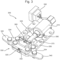
- the motive assembly 300 of the cover mechanism are illustrated in Figure 3 .
- the ejection of the cover 100 is initiated by a pyrotechnic actuator 310 located at the air intake end of the motive assembly.
- the pyrotechnic actuator operates to move a push rod 320 aligned with the missile axis in a direction parallel to the missile axis, and away from the air intake.
- push rod 320 is connected to a linkage mechanism, indicated generally at 330 and described further below, which in the present embodiment is a form of scissor linkage, which connects with locking arms 340.
- the components of the motive assembly 300 are held in place by means of a retaining structure 350.
- the retaining structure 350 can be further arranged to constrain the movements of the push rod on operation of the pyrotechnic actuator, for example by providing holes through which the push rod 320 moves, and by the provision of slots co-operating with projections on the push rod 320 itself.
- the linkage mechanism is shown in Figures 2 and 3 in a first configuration in which locking arms 340 are extended perpendicularly outward from the motive assembly.
- the locking arms 340 extend outwardly from slots formed in the housing of the cover 100, and, in use, into the slots 16 in the missile body described above with reference to Figure 1 .
- a shear pin 360 passing through the retaining structure and the push rod holds the motive assembly in this first configuration, preventing the locking arms from retracting as a result of vibration or other motions prior to launch of the missile.
- Linkage mechanism 330 includes a coupler linkage 332 attached to the push rod 320 by a circlip 325.
- the coupler linkage 332 extends perpendicularly to the push rod 320 and, at its opposing ends, is pivotally connected to locking arms 340.
- the locking arms 340 are further connected to the retaining structure 350 by links 334.
- Each link is pivotally connected to the retaining structure 350 and to a point approximately midway along its respective locking arm 340 so that, in the extended, locked configuration, the ends of the locking arms project beyond the pivot point, through slots in the cover housing, and, in use, into the missile body.
- the dimensions and geometry of the linkage mechanism will be determined to fit with the dimensions of the missile with which the cover is to be used.
- the motive assembly 300 also includes a rotational follower 370, which cooperates with a sliding cam 380.
- Rotational follower 370 is described in further detail below with reference to Figures 5a to 5c , but in brief its function is to push the cover 100 upwards on operation of the actuator, so that the cover is lifted into the airstream around the missile and thus removed from the air intake.
- the ballast weight 130 illustrated in Figure 1 , is selected to have a mass that moves the centre of gravity of the cover 100 to the fore of the rotational follower. This aids predictable dispersion of the cover subsequent to ejection, and improves the likelihood of a satisfactory trajectory of the cover after ejection.
- Connector 390 communicates with the connector 18 on the missile body, and is electrically connected to the pyrotechnic actuator 310. This connection enables a signal to be passed to the pyrotechnic actuator so as to eject the cover 100 from the missile a suitable time after launch.
- the connection between the cover 100 and the missile is arranged so as not to impede in any significant way the ejection of the cover.
- the connector 390 comprises three spring-loaded pins which, when in place on the missile, are pushed against the corresponding connector 18 on the missile air intake wall.
- Figures 4a and 4b show the locking parts of the motive assembly in their extended configuration and retracted configuration respectively.
- Figure 4a is similar to Figure 3 , except in that certain parts of the motive assembly, such as the connector and the rotational follower, are not shown for clarity.
- the push rod 320 is extended forwards and the locking arms 340 are thus retracted.
- the push rod is moved forwards by operation of the pyrotechnic actuator 310, constrained to linear motion as described above by means of the retaining structure 350.
- the pyrotechnic actuator operates with sufficient force to break the shear pin, freeing the push rod to move constrained only by the retaining structure 350.
- Figures 5a to 5c illustrate the operation of the ejection mechanism from an alternative perspective, showing in particular the motion of the rotational follower 370 and the consequential outward motion of the cover 100.
- Figure 5a illustrates the cover in locked position within the detent 12 formed by a missile air intake.
- cover housing 120 includes a hook structure 125 which, in locked position on the missile, cooperates with the lip of the air intake so as to form a pivot point about which the cover can rotate as it is ejected.
- the motive assembly with the pyrotechnic actuator is shown in cross-section.
- rotational follower 370 is seen, in Figure 5a , aligned with the surface of the detent 12 formed in the missile body tube, and attached to the retaining structure of the motive assembly at pivot 375.
- Sliding cam 380 in Figure 5a is in its retracted position, some distance away from the rotational follower 370. In the present embodiment this distance is approximately 5 mm.
- Figure 5b shows an intermediate stage after operation of the pyrotechnic actuator 310.
- the shear pin 360 has been broken and the sliding cam 380 has moved forwards but has not yet contacted the rotational follower 370.
- this enables the functions of breaking the shear pin, retraction of the locking arms, and the pivoting of the rotational follower are separated.
- the locking arms (not shown in Figures 5a to 5c ) are retracted sufficiently to be removed from the cavities in the missile body tube, as a result of the motion of the push rod acting on the linkage mechanism, as described above, so that the cover mechanism is free to move away from the missile air intake before the sliding cam contacts the rotational follower. This assists in preventing jamming.
- Figure 5c shows the cover after the motion of the pyrotechnic actuator 310 is complete.
- the actuator 310 causes the push rod 320 to move forwards by approximately 10 mm.
- the sliding cam 380 has now made contact with the rotational follower 370 and pushed its upper (as shown) portion forwards, causing it to rotate about pivot 375 and push downwards on the missile body.
- the hook structure ensures that it is the forward part of the cover that is pushed upwards. As illustrated by arrow 500 in Figure 5c , this ensures that the cover is caught by the airflow past the missile, in turn creating sufficient force to entirely remove the cover 100 from the missile.
- the centre of gravity of the cover 100 is moved forwards.
- the force of the air flow can be considered as acting on the cover at its centre of gravity, and it will now be seen that moving the centre of gravity reduces the moment created by the air flow about the pivot. In turn this reduces the likelihood of the cover tumbling away from missile in an unpredictable manner.
- actuator may include self-locking devices to prevent movement in the absence of a signal, in which case it may not be necessary to include the shear pin as described above to hold the locking arms in position.
- Alternative forms of connector will also be possible, in particular inductive connections or other forms of connection that do not require a mechanical link between the missile and the cover mechanism.
Landscapes
- Engineering & Computer Science (AREA)
- Chemical & Material Sciences (AREA)
- Combustion & Propulsion (AREA)
- Aviation & Aerospace Engineering (AREA)
- General Engineering & Computer Science (AREA)
- Physics & Mathematics (AREA)
- Geometry (AREA)
- Mechanical Engineering (AREA)
- Aiming, Guidance, Guns With A Light Source, Armor, Camouflage, And Targets (AREA)
- Transmission Devices (AREA)
Claims (14)
- Abdeckung (100) für einen Einlass (14) eines luftatmenden Triebwerks in einem Flugkörper (10), die Abdeckung (100) umfassend eine Antriebsanordnung (300), die betriebsfähig ist, um sich von einer ersten Konfiguration, in der die Abdeckung (100) an einem Flugkörper (10) verriegelbar ist, zu einer zweiten Konfiguration, in der die Abdeckung (10) von dem Flugkörper (10) nach außen geschoben wird, zu bewegen; wobei in der ersten Konfiguration die Oberfläche der Abdeckung (100) mit der Oberfläche des Flugkörpers (10) bündig ist und die Antriebsanordnung (300) nach innen der Abdeckoberfläche gelegen ist, und wobei die Antriebsanordnung (300) einen Verknüpfungsmechanismus (330) umfasst, wobei sich der Verknüpfungsmechanismus (330), in der ersten Konfiguration, in einer ersten Richtung derart erstreckt, dass die Abdeckung (100) in Verwendung an dem Flugkörper (10) verriegelt ist, und wobei, in der zweiten Konfiguration, der Verknüpfungsmechanismus in der ersten Richtung derart zusammengezogen ist, dass die Abdeckung (100) von dem Flugkörper (10) entfernbar ist.
- Abdeckung (100) nach Anspruch 1, wobei die Antriebsanordnung (300) einen Aktuator (310) umfasst, der betriebsfähig ist, um die Antriebsanordnung (300) von der ersten Konfiguration in die zweite Konfiguration zu bewegen.
- Abdeckung (100) nach einem der Ansprüche 1 oder 2, wobei die Antriebsanordnung (300), wenn sie sich von der ersten Konfiguration in die zweite Konfiguration bewegt, konfiguriert ist, um sich durch eine Zwischenkonfiguration zu bewegen, in der die Abdeckung (100) von dem Flugkörper (10) entfernbar ist, aber nicht von dem Flugkörper (10) nach außen geschoben wird.
- Abdeckung (100) nach einem der vorstehenden Ansprüche, ferner umfassend eine Hakenstruktur (125), die derart angeordnet ist, dass, wenn sie an dem Lufteinlass angebracht ist, die Hakenstruktur mit der Lippe des Lufteinlasses (14) zusammenwirkt, um einen Drehpunkt auszubilden, um den die Abdeckung (100) rotiert, wenn sie von dem Flugkörper (10) nach außen geschoben wird.
- Abdeckung (100) nach einem der vorstehenden Ansprüche, wobei die Antriebsanordnung (300) ferner einen Nocken- (380) und Folge- (370) Mechanismus umfasst, der angeordnet ist, um die Abdeckung (100) nach außen von dem Flugkörper (10) zu schieben, wenn die Antriebsanordnung (300) in die zweite Konfiguration bewegt wird.
- Abdeckung (100) nach einem der Ansprüche 2 bis 5, wobei der Aktuator (310) einen linearen Aktuator umfasst, der betriebsfähig ist, um sich in eine zweite Richtung zu erstrecken, um die Antriebsanordnung (300) von der ersten Konfiguration in die zweite Konfiguration zu bewegen.
- Abdeckung (100) nach Anspruch 6, wenn abhängig von Anspruch 5, wobei der Nocken (380) einen Gleitnocken umfasst, der an einer linearen Schubstange (320) bereitgestellt ist, auf dem der lineare Aktuator (310) in Betrieb ist.
- Abdeckung (100) nach einem der vorstehenden Ansprüche, wobei der Verknüpfungsmechanismus (330) einen Verriegelungsarm (340) umfasst, der angeordnet ist, um sich in die erste Richtung zurückzuziehen, wenn sich die Antriebsanordnung (300) von der ersten Konfiguration in die zweite Konfiguration bewegt.
- Abdeckung (100) nach einem der vorstehenden Ansprüche, ferner umfassend Mittel (360), um die Antriebsanordnung (300) in der ersten Konfiguration zu halten.
- Abdeckung nach Anspruch 9, wenn abhängig von Anspruch 2, wobei die Mittel einen zerbrechlichen Scherstift (360) umfassen, der konfiguriert ist, um bei einem Betreiben des Aktuators (310) zu brechen.
- Abdeckung (100) nach einem der vorstehenden Ansprüche, ferner umfassend ein Ballastgewicht (130), das derart angeordnet ist, dass der Schwerpunkt der Abdeckung (100) zu der Vorderseite der Abdeckung (100) hin gelegen ist.
- Flugkörper (10), der ein luftatmendes Triebwerk und einen Einlass (14) für das luftatmende Triebwerk aufweist, der Flugkörper (10) umfassend eine Abdeckung (100) nach einem der Ansprüche 1 bis 11, die den Einlass (14) abdeckt, wobei sich die Abdeckung (100) in der ersten Konfiguration befindet, derart, dass die Oberfläche der Abdeckung (100) mit der Oberfläche des Flugkörpers (10) bündig ist und die Antriebsanordnung (300) innerhalb des Einlasses (14) gelegen ist, wobei die Abdeckung (100) mit dem Flugkörper (10) in Verbindung steht, derart, dass sich die Abdeckung (100) bei einem Empfang eines Signals von dem Flugkörper (10) in die zweite Konfiguration bewegt und von dem Flugkörper (10) ausgestoßen wird.
- Flugkörper (10) nach Anspruch 12, wobei der Lufteinlass (14) mit Mitteln (16) versehen ist, die angeordnet sind, um mit der Abdeckung (100) derart zusammenwirken, dass die Abdeckung (100) mit dem Flugkörper (10) in der ersten Konfiguration verriegelt werden kann.
- Flugkörper nach Anspruch 13, wenn abhängig von Anspruch 8, wobei die Mittel Schlitze (16) umfassen, die angeordnet sind, um den Verriegelungsarm (340) aufzunehmen.
Applications Claiming Priority (3)
| Application Number | Priority Date | Filing Date | Title |
|---|---|---|---|
| GBGB1720377.9A GB201720377D0 (en) | 2017-12-07 | 2017-12-07 | Air intake cover |
| EP18151822.6A EP3511671A1 (de) | 2018-01-16 | 2018-01-16 | Lufteinlassabdeckung |
| PCT/GB2018/053416 WO2019110958A1 (en) | 2017-12-07 | 2018-11-27 | Air intake cover |
Publications (3)
| Publication Number | Publication Date |
|---|---|
| EP3721164A1 EP3721164A1 (de) | 2020-10-14 |
| EP3721164C0 EP3721164C0 (de) | 2024-06-19 |
| EP3721164B1 true EP3721164B1 (de) | 2024-06-19 |
Family
ID=64556940
Family Applications (1)
| Application Number | Title | Priority Date | Filing Date |
|---|---|---|---|
| EP18811335.1A Active EP3721164B1 (de) | 2017-12-07 | 2018-11-27 | Lufteinlassabdeckung |
Country Status (8)
| Country | Link |
|---|---|
| US (1) | US11577851B2 (de) |
| EP (1) | EP3721164B1 (de) |
| AU (1) | AU2018379680B2 (de) |
| CA (1) | CA3084432A1 (de) |
| ES (1) | ES2984987T3 (de) |
| IL (1) | IL275143B2 (de) |
| PL (1) | PL3721164T3 (de) |
| WO (1) | WO2019110958A1 (de) |
Family Cites Families (5)
| Publication number | Priority date | Publication date | Assignee | Title |
|---|---|---|---|---|
| US2362552A (en) * | 1943-04-02 | 1944-11-14 | Stewart Warner Corp | Scoop for aircraft |
| US3659424A (en) * | 1970-10-07 | 1972-05-02 | Us Navy | Stowable air scoop |
| US4121606A (en) * | 1977-10-25 | 1978-10-24 | General Dynamics Corporation | Inflatable air inlet duct |
| US6142417A (en) * | 1998-10-26 | 2000-11-07 | Atlantic Research Corporation | Self-deploying air inlet for an air breathing missile |
| US6880780B1 (en) * | 2003-03-17 | 2005-04-19 | General Dynamics Ordnance And Tactical Systems, Inc. | Cover ejection and fin deployment system for a gun-launched projectile |
-
2018
- 2018-11-27 WO PCT/GB2018/053416 patent/WO2019110958A1/en not_active Ceased
- 2018-11-27 PL PL18811335.1T patent/PL3721164T3/pl unknown
- 2018-11-27 ES ES18811335T patent/ES2984987T3/es active Active
- 2018-11-27 US US16/770,688 patent/US11577851B2/en active Active
- 2018-11-27 IL IL275143A patent/IL275143B2/en unknown
- 2018-11-27 CA CA3084432A patent/CA3084432A1/en active Pending
- 2018-11-27 EP EP18811335.1A patent/EP3721164B1/de active Active
- 2018-11-27 AU AU2018379680A patent/AU2018379680B2/en active Active
Also Published As
| Publication number | Publication date |
|---|---|
| EP3721164C0 (de) | 2024-06-19 |
| IL275143A (en) | 2020-07-30 |
| AU2018379680B2 (en) | 2024-06-20 |
| US11577851B2 (en) | 2023-02-14 |
| WO2019110958A1 (en) | 2019-06-13 |
| ES2984987T3 (es) | 2024-10-31 |
| US20210163145A1 (en) | 2021-06-03 |
| AU2018379680A1 (en) | 2020-06-18 |
| CA3084432A1 (en) | 2019-06-13 |
| IL275143B2 (en) | 2025-03-01 |
| IL275143B1 (en) | 2024-11-01 |
| PL3721164T3 (pl) | 2024-08-12 |
| EP3721164A1 (de) | 2020-10-14 |
Similar Documents
| Publication | Publication Date | Title |
|---|---|---|
| US6446906B1 (en) | Fin and cover release system | |
| US3008376A (en) | Launching device | |
| US10054411B2 (en) | Missile provided with a separable protective fairing | |
| US7475846B2 (en) | Fin retention and deployment mechanism | |
| US5660357A (en) | Airstream ejected missile engine inlet cover | |
| US8002599B2 (en) | Systems and methods for underwater descent rate reduction | |
| EP3721164B1 (de) | Lufteinlassabdeckung | |
| GB2569236A (en) | Air intake cover | |
| US7762194B2 (en) | Apparatus comprising a payload ejection mechanism | |
| CN114852346A (zh) | 用于飞机的座舱罩分离系统和方法 | |
| EP3511671A1 (de) | Lufteinlassabdeckung | |
| EP3412903A1 (de) | Lufteinlassabdeckung | |
| CN116096503A (zh) | 喷出装置及无人机 | |
| EP0437983A1 (de) | Betätigungseinrichtung für eine Flugzeughaube oder eine Platte | |
| US12280872B2 (en) | Winged store mechanical capture interface for use with an aircraft | |
| KR102573343B1 (ko) | 공기 흡입구 개폐 장치 | |
| EP3635235B1 (de) | Lufteinlassabdeckung | |
| KR101833625B1 (ko) | 외력에 의한 날개의 흔들림 방지장치 | |
| JP4712515B2 (ja) | 接続及び分離装置 | |
| US10578056B2 (en) | Spacecraft nozzle comprising an improved deployment system | |
| KR102804002B1 (ko) | 날개 가변타입 발사형 무인기 및 상기 날개 가변타입 발사형 무인기의 발사를 위한 날개 가변타입 발사형 무인기용 캐니스터 장치 | |
| GB2563230A (en) | Air intake cover | |
| WO2004099707A2 (en) | Winged vehicle with deployable wings mounted to a translating pivot mechanism | |
| JP2025541194A (ja) | 回転可能に結合された剛性部材を、湾曲した部材の張力を保持後に解放することを介してフレームに固定後にフレームから展開するための機構 | |
| US10730625B1 (en) | Payload ejector with shock attenuation device |
Legal Events
| Date | Code | Title | Description |
|---|---|---|---|
| STAA | Information on the status of an ep patent application or granted ep patent |
Free format text: STATUS: UNKNOWN |
|
| STAA | Information on the status of an ep patent application or granted ep patent |
Free format text: STATUS: THE INTERNATIONAL PUBLICATION HAS BEEN MADE |
|
| PUAI | Public reference made under article 153(3) epc to a published international application that has entered the european phase |
Free format text: ORIGINAL CODE: 0009012 |
|
| STAA | Information on the status of an ep patent application or granted ep patent |
Free format text: STATUS: REQUEST FOR EXAMINATION WAS MADE |
|
| 17P | Request for examination filed |
Effective date: 20200616 |
|
| AK | Designated contracting states |
Kind code of ref document: A1 Designated state(s): AL AT BE BG CH CY CZ DE DK EE ES FI FR GB GR HR HU IE IS IT LI LT LU LV MC MK MT NL NO PL PT RO RS SE SI SK SM TR |
|
| AX | Request for extension of the european patent |
Extension state: BA ME |
|
| DAV | Request for validation of the european patent (deleted) | ||
| DAX | Request for extension of the european patent (deleted) | ||
| STAA | Information on the status of an ep patent application or granted ep patent |
Free format text: STATUS: EXAMINATION IS IN PROGRESS |
|
| 17Q | First examination report despatched |
Effective date: 20230224 |
|
| REG | Reference to a national code |
Ref country code: DE Ref legal event code: R079 Free format text: PREVIOUS MAIN CLASS: F42B0010320000 Ipc: F42B0015000000 Ref country code: DE Ref legal event code: R079 Ref document number: 602018070829 Country of ref document: DE Free format text: PREVIOUS MAIN CLASS: F42B0010320000 Ipc: F42B0015000000 |
|
| GRAP | Despatch of communication of intention to grant a patent |
Free format text: ORIGINAL CODE: EPIDOSNIGR1 |
|
| STAA | Information on the status of an ep patent application or granted ep patent |
Free format text: STATUS: GRANT OF PATENT IS INTENDED |
|
| RIC1 | Information provided on ipc code assigned before grant |
Ipc: B64D 33/02 20060101ALI20231221BHEP Ipc: F02C 7/042 20060101ALI20231221BHEP Ipc: F42B 15/00 20060101AFI20231221BHEP |
|
| INTG | Intention to grant announced |
Effective date: 20240123 |
|
| GRAS | Grant fee paid |
Free format text: ORIGINAL CODE: EPIDOSNIGR3 |
|
| GRAA | (expected) grant |
Free format text: ORIGINAL CODE: 0009210 |
|
| STAA | Information on the status of an ep patent application or granted ep patent |
Free format text: STATUS: THE PATENT HAS BEEN GRANTED |
|
| AK | Designated contracting states |
Kind code of ref document: B1 Designated state(s): AL AT BE BG CH CY CZ DE DK EE ES FI FR GR HR HU IE IS IT LI LT LU LV MC MK MT NL NO PL PT RO RS SE SI SK SM TR |
|
| RBV | Designated contracting states (corrected) |
Designated state(s): AL AT BE BG CH CY CZ DE DK EE ES FI FR GR HR HU IE IS IT LI LT LU LV MC MK MT NL NO PL PT RO RS SE SI SK SM TR |
|
| REG | Reference to a national code |
Ref country code: CH Ref legal event code: EP |
|
| REG | Reference to a national code |
Ref country code: DE Ref legal event code: R096 Ref document number: 602018070829 Country of ref document: DE |
|
| U01 | Request for unitary effect filed |
Effective date: 20240717 |
|
| U07 | Unitary effect registered |
Designated state(s): AT BE BG DE DK EE FI FR IT LT LU LV MT NL PT SE SI Effective date: 20240725 |
|
| PG25 | Lapsed in a contracting state [announced via postgrant information from national office to epo] |
Ref country code: HR Free format text: LAPSE BECAUSE OF FAILURE TO SUBMIT A TRANSLATION OF THE DESCRIPTION OR TO PAY THE FEE WITHIN THE PRESCRIBED TIME-LIMIT Effective date: 20240619 |
|
| PG25 | Lapsed in a contracting state [announced via postgrant information from national office to epo] |
Ref country code: GR Free format text: LAPSE BECAUSE OF FAILURE TO SUBMIT A TRANSLATION OF THE DESCRIPTION OR TO PAY THE FEE WITHIN THE PRESCRIBED TIME-LIMIT Effective date: 20240920 |
|
| PG25 | Lapsed in a contracting state [announced via postgrant information from national office to epo] |
Ref country code: NO Free format text: LAPSE BECAUSE OF FAILURE TO SUBMIT A TRANSLATION OF THE DESCRIPTION OR TO PAY THE FEE WITHIN THE PRESCRIBED TIME-LIMIT Effective date: 20240919 Ref country code: HR Free format text: LAPSE BECAUSE OF FAILURE TO SUBMIT A TRANSLATION OF THE DESCRIPTION OR TO PAY THE FEE WITHIN THE PRESCRIBED TIME-LIMIT Effective date: 20240619 Ref country code: GR Free format text: LAPSE BECAUSE OF FAILURE TO SUBMIT A TRANSLATION OF THE DESCRIPTION OR TO PAY THE FEE WITHIN THE PRESCRIBED TIME-LIMIT Effective date: 20240920 Ref country code: RS Free format text: LAPSE BECAUSE OF FAILURE TO SUBMIT A TRANSLATION OF THE DESCRIPTION OR TO PAY THE FEE WITHIN THE PRESCRIBED TIME-LIMIT Effective date: 20240919 |
|
| REG | Reference to a national code |
Ref country code: ES Ref legal event code: FG2A Ref document number: 2984987 Country of ref document: ES Kind code of ref document: T3 Effective date: 20241031 |
|
| U20 | Renewal fee for the european patent with unitary effect paid |
Year of fee payment: 7 Effective date: 20241022 |
|
| PG25 | Lapsed in a contracting state [announced via postgrant information from national office to epo] |
Ref country code: IS Free format text: LAPSE BECAUSE OF FAILURE TO SUBMIT A TRANSLATION OF THE DESCRIPTION OR TO PAY THE FEE WITHIN THE PRESCRIBED TIME-LIMIT Effective date: 20241019 |
|
| PG25 | Lapsed in a contracting state [announced via postgrant information from national office to epo] |
Ref country code: CZ Free format text: LAPSE BECAUSE OF FAILURE TO SUBMIT A TRANSLATION OF THE DESCRIPTION OR TO PAY THE FEE WITHIN THE PRESCRIBED TIME-LIMIT Effective date: 20240619 |
|
| PG25 | Lapsed in a contracting state [announced via postgrant information from national office to epo] |
Ref country code: RO Free format text: LAPSE BECAUSE OF FAILURE TO SUBMIT A TRANSLATION OF THE DESCRIPTION OR TO PAY THE FEE WITHIN THE PRESCRIBED TIME-LIMIT Effective date: 20240619 Ref country code: SK Free format text: LAPSE BECAUSE OF FAILURE TO SUBMIT A TRANSLATION OF THE DESCRIPTION OR TO PAY THE FEE WITHIN THE PRESCRIBED TIME-LIMIT Effective date: 20240619 |
|
| PG25 | Lapsed in a contracting state [announced via postgrant information from national office to epo] |
Ref country code: SM Free format text: LAPSE BECAUSE OF FAILURE TO SUBMIT A TRANSLATION OF THE DESCRIPTION OR TO PAY THE FEE WITHIN THE PRESCRIBED TIME-LIMIT Effective date: 20240619 |
|
| PG25 | Lapsed in a contracting state [announced via postgrant information from national office to epo] |
Ref country code: SM Free format text: LAPSE BECAUSE OF FAILURE TO SUBMIT A TRANSLATION OF THE DESCRIPTION OR TO PAY THE FEE WITHIN THE PRESCRIBED TIME-LIMIT Effective date: 20240619 Ref country code: SK Free format text: LAPSE BECAUSE OF FAILURE TO SUBMIT A TRANSLATION OF THE DESCRIPTION OR TO PAY THE FEE WITHIN THE PRESCRIBED TIME-LIMIT Effective date: 20240619 Ref country code: RO Free format text: LAPSE BECAUSE OF FAILURE TO SUBMIT A TRANSLATION OF THE DESCRIPTION OR TO PAY THE FEE WITHIN THE PRESCRIBED TIME-LIMIT Effective date: 20240619 Ref country code: IS Free format text: LAPSE BECAUSE OF FAILURE TO SUBMIT A TRANSLATION OF THE DESCRIPTION OR TO PAY THE FEE WITHIN THE PRESCRIBED TIME-LIMIT Effective date: 20241019 Ref country code: CZ Free format text: LAPSE BECAUSE OF FAILURE TO SUBMIT A TRANSLATION OF THE DESCRIPTION OR TO PAY THE FEE WITHIN THE PRESCRIBED TIME-LIMIT Effective date: 20240619 |
|
| PLBE | No opposition filed within time limit |
Free format text: ORIGINAL CODE: 0009261 |
|
| STAA | Information on the status of an ep patent application or granted ep patent |
Free format text: STATUS: NO OPPOSITION FILED WITHIN TIME LIMIT |
|
| 26N | No opposition filed |
Effective date: 20250320 |
|
| REG | Reference to a national code |
Ref country code: CH Ref legal event code: PL |
|
| PG25 | Lapsed in a contracting state [announced via postgrant information from national office to epo] |
Ref country code: MC Free format text: LAPSE BECAUSE OF FAILURE TO SUBMIT A TRANSLATION OF THE DESCRIPTION OR TO PAY THE FEE WITHIN THE PRESCRIBED TIME-LIMIT Effective date: 20240619 |
|
| REG | Reference to a national code |
Ref country code: CH Ref legal event code: PL |
|
| PG25 | Lapsed in a contracting state [announced via postgrant information from national office to epo] |
Ref country code: CH Free format text: LAPSE BECAUSE OF NON-PAYMENT OF DUE FEES Effective date: 20241130 |
|
| PG25 | Lapsed in a contracting state [announced via postgrant information from national office to epo] |
Ref country code: IE Free format text: LAPSE BECAUSE OF NON-PAYMENT OF DUE FEES Effective date: 20241127 |
|
| U20 | Renewal fee for the european patent with unitary effect paid |
Year of fee payment: 8 Effective date: 20251022 |
|
| PGFP | Annual fee paid to national office [announced via postgrant information from national office to epo] |
Ref country code: PL Payment date: 20251023 Year of fee payment: 8 |
|
| PGFP | Annual fee paid to national office [announced via postgrant information from national office to epo] |
Ref country code: ES Payment date: 20251201 Year of fee payment: 8 |
|
| PG25 | Lapsed in a contracting state [announced via postgrant information from national office to epo] |
Ref country code: HU Free format text: LAPSE BECAUSE OF FAILURE TO SUBMIT A TRANSLATION OF THE DESCRIPTION OR TO PAY THE FEE WITHIN THE PRESCRIBED TIME-LIMIT; INVALID AB INITIO Effective date: 20181127 |
|
| PG25 | Lapsed in a contracting state [announced via postgrant information from national office to epo] |
Ref country code: CY Free format text: LAPSE BECAUSE OF FAILURE TO SUBMIT A TRANSLATION OF THE DESCRIPTION OR TO PAY THE FEE WITHIN THE PRESCRIBED TIME-LIMIT; INVALID AB INITIO Effective date: 20181127 |