EP3721168B1 - Method of non-destructive imaging of the internal structure of an object and device for carrying out the method - Google Patents
Method of non-destructive imaging of the internal structure of an object and device for carrying out the method Download PDFInfo
- Publication number
- EP3721168B1 EP3721168B1 EP18830131.1A EP18830131A EP3721168B1 EP 3721168 B1 EP3721168 B1 EP 3721168B1 EP 18830131 A EP18830131 A EP 18830131A EP 3721168 B1 EP3721168 B1 EP 3721168B1
- Authority
- EP
- European Patent Office
- Prior art keywords
- virtual image
- internal structure
- radiation
- scanning
- virtual
- Prior art date
- Legal status (The legal status is an assumption and is not a legal conclusion. Google has not performed a legal analysis and makes no representation as to the accuracy of the status listed.)
- Active
Links
Images
Classifications
-
- G—PHYSICS
- G01—MEASURING; TESTING
- G01B—MEASURING LENGTH, THICKNESS OR SIMILAR LINEAR DIMENSIONS; MEASURING ANGLES; MEASURING AREAS; MEASURING IRREGULARITIES OF SURFACES OR CONTOURS
- G01B11/00—Measuring arrangements characterised by the use of optical techniques
- G01B11/24—Measuring arrangements characterised by the use of optical techniques for measuring contours or curvatures
-
- G—PHYSICS
- G01—MEASURING; TESTING
- G01N—INVESTIGATING OR ANALYSING MATERIALS BY DETERMINING THEIR CHEMICAL OR PHYSICAL PROPERTIES
- G01N23/00—Investigating or analysing materials by the use of wave or particle radiation, e.g. X-rays or neutrons, not covered by groups G01N3/00 – G01N17/00, G01N21/00 or G01N22/00
- G01N23/02—Investigating or analysing materials by the use of wave or particle radiation, e.g. X-rays or neutrons, not covered by groups G01N3/00 – G01N17/00, G01N21/00 or G01N22/00 by transmitting the radiation through the material
- G01N23/04—Investigating or analysing materials by the use of wave or particle radiation, e.g. X-rays or neutrons, not covered by groups G01N3/00 – G01N17/00, G01N21/00 or G01N22/00 by transmitting the radiation through the material and forming images of the material
- G01N23/046—Investigating or analysing materials by the use of wave or particle radiation, e.g. X-rays or neutrons, not covered by groups G01N3/00 – G01N17/00, G01N21/00 or G01N22/00 by transmitting the radiation through the material and forming images of the material using tomography, e.g. computed tomography [CT]
-
- G—PHYSICS
- G01—MEASURING; TESTING
- G01N—INVESTIGATING OR ANALYSING MATERIALS BY DETERMINING THEIR CHEMICAL OR PHYSICAL PROPERTIES
- G01N23/00—Investigating or analysing materials by the use of wave or particle radiation, e.g. X-rays or neutrons, not covered by groups G01N3/00 – G01N17/00, G01N21/00 or G01N22/00
- G01N23/02—Investigating or analysing materials by the use of wave or particle radiation, e.g. X-rays or neutrons, not covered by groups G01N3/00 – G01N17/00, G01N21/00 or G01N22/00 by transmitting the radiation through the material
- G01N23/04—Investigating or analysing materials by the use of wave or particle radiation, e.g. X-rays or neutrons, not covered by groups G01N3/00 – G01N17/00, G01N21/00 or G01N22/00 by transmitting the radiation through the material and forming images of the material
- G01N23/044—Investigating or analysing materials by the use of wave or particle radiation, e.g. X-rays or neutrons, not covered by groups G01N3/00 – G01N17/00, G01N21/00 or G01N22/00 by transmitting the radiation through the material and forming images of the material using laminography or tomosynthesis
-
- G—PHYSICS
- G01—MEASURING; TESTING
- G01N—INVESTIGATING OR ANALYSING MATERIALS BY DETERMINING THEIR CHEMICAL OR PHYSICAL PROPERTIES
- G01N23/00—Investigating or analysing materials by the use of wave or particle radiation, e.g. X-rays or neutrons, not covered by groups G01N3/00 – G01N17/00, G01N21/00 or G01N22/00
- G01N23/02—Investigating or analysing materials by the use of wave or particle radiation, e.g. X-rays or neutrons, not covered by groups G01N3/00 – G01N17/00, G01N21/00 or G01N22/00 by transmitting the radiation through the material
- G01N23/06—Investigating or analysing materials by the use of wave or particle radiation, e.g. X-rays or neutrons, not covered by groups G01N3/00 – G01N17/00, G01N21/00 or G01N22/00 by transmitting the radiation through the material and measuring the absorption
- G01N23/083—Investigating or analysing materials by the use of wave or particle radiation, e.g. X-rays or neutrons, not covered by groups G01N3/00 – G01N17/00, G01N21/00 or G01N22/00 by transmitting the radiation through the material and measuring the absorption the radiation being X-rays
-
- G—PHYSICS
- G01—MEASURING; TESTING
- G01N—INVESTIGATING OR ANALYSING MATERIALS BY DETERMINING THEIR CHEMICAL OR PHYSICAL PROPERTIES
- G01N23/00—Investigating or analysing materials by the use of wave or particle radiation, e.g. X-rays or neutrons, not covered by groups G01N3/00 – G01N17/00, G01N21/00 or G01N22/00
- G01N23/02—Investigating or analysing materials by the use of wave or particle radiation, e.g. X-rays or neutrons, not covered by groups G01N3/00 – G01N17/00, G01N21/00 or G01N22/00 by transmitting the radiation through the material
- G01N23/06—Investigating or analysing materials by the use of wave or particle radiation, e.g. X-rays or neutrons, not covered by groups G01N3/00 – G01N17/00, G01N21/00 or G01N22/00 by transmitting the radiation through the material and measuring the absorption
- G01N23/18—Investigating the presence of flaws defects or foreign matter
-
- G—PHYSICS
- G01—MEASURING; TESTING
- G01N—INVESTIGATING OR ANALYSING MATERIALS BY DETERMINING THEIR CHEMICAL OR PHYSICAL PROPERTIES
- G01N29/00—Investigating or analysing materials by the use of ultrasonic, sonic or infrasonic waves; Visualisation of the interior of objects by transmitting ultrasonic or sonic waves through the object
- G01N29/04—Analysing solids
- G01N29/06—Visualisation of the interior, e.g. acoustic microscopy
- G01N29/0609—Display arrangements, e.g. colour displays
- G01N29/0618—Display arrangements, e.g. colour displays synchronised with scanning, e.g. in real-time
-
- G—PHYSICS
- G01—MEASURING; TESTING
- G01N—INVESTIGATING OR ANALYSING MATERIALS BY DETERMINING THEIR CHEMICAL OR PHYSICAL PROPERTIES
- G01N29/00—Investigating or analysing materials by the use of ultrasonic, sonic or infrasonic waves; Visualisation of the interior of objects by transmitting ultrasonic or sonic waves through the object
- G01N29/04—Analysing solids
- G01N29/06—Visualisation of the interior, e.g. acoustic microscopy
- G01N29/0654—Imaging
- G01N29/0672—Imaging by acoustic tomography
-
- G—PHYSICS
- G01—MEASURING; TESTING
- G01N—INVESTIGATING OR ANALYSING MATERIALS BY DETERMINING THEIR CHEMICAL OR PHYSICAL PROPERTIES
- G01N29/00—Investigating or analysing materials by the use of ultrasonic, sonic or infrasonic waves; Visualisation of the interior of objects by transmitting ultrasonic or sonic waves through the object
- G01N29/22—Details, e.g. general constructional or apparatus details
- G01N29/26—Arrangements for orientation or scanning by relative movement of the head and the sensor
- G01N29/265—Arrangements for orientation or scanning by relative movement of the head and the sensor by moving the sensor relative to a stationary material
-
- G—PHYSICS
- G06—COMPUTING OR CALCULATING; COUNTING
- G06T—IMAGE DATA PROCESSING OR GENERATION, IN GENERAL
- G06T19/00—Manipulating three-dimensional [3D] models or images for computer graphics
- G06T19/006—Mixed reality
-
- G—PHYSICS
- G06—COMPUTING OR CALCULATING; COUNTING
- G06T—IMAGE DATA PROCESSING OR GENERATION, IN GENERAL
- G06T7/00—Image analysis
- G06T7/0002—Inspection of images, e.g. flaw detection
- G06T7/0004—Industrial image inspection
-
- H—ELECTRICITY
- H04—ELECTRIC COMMUNICATION TECHNIQUE
- H04N—PICTORIAL COMMUNICATION, e.g. TELEVISION
- H04N13/00—Stereoscopic video systems; Multi-view video systems; Details thereof
- H04N13/30—Image reproducers
- H04N13/332—Displays for viewing with the aid of special glasses or head-mounted displays [HMD]
- H04N13/344—Displays for viewing with the aid of special glasses or head-mounted displays [HMD] with head-mounted left-right displays
-
- G—PHYSICS
- G01—MEASURING; TESTING
- G01N—INVESTIGATING OR ANALYSING MATERIALS BY DETERMINING THEIR CHEMICAL OR PHYSICAL PROPERTIES
- G01N21/00—Investigating or analysing materials by the use of optical means, i.e. using sub-millimetre waves, infrared, visible or ultraviolet light
- G01N21/01—Arrangements or apparatus for facilitating the optical investigation
- G01N2021/0162—Arrangements or apparatus for facilitating the optical investigation using microprocessors for control of a sequence of operations, e.g. test, powering, switching, processing
-
- G—PHYSICS
- G01—MEASURING; TESTING
- G01N—INVESTIGATING OR ANALYSING MATERIALS BY DETERMINING THEIR CHEMICAL OR PHYSICAL PROPERTIES
- G01N21/00—Investigating or analysing materials by the use of optical means, i.e. using sub-millimetre waves, infrared, visible or ultraviolet light
- G01N21/17—Systems in which incident light is modified in accordance with the properties of the material investigated
- G01N2021/1765—Method using an image detector and processing of image signal
- G01N2021/177—Detector of the video camera type
- G01N2021/1776—Colour camera
-
- G—PHYSICS
- G01—MEASURING; TESTING
- G01N—INVESTIGATING OR ANALYSING MATERIALS BY DETERMINING THEIR CHEMICAL OR PHYSICAL PROPERTIES
- G01N2223/00—Investigating materials by wave or particle radiation
- G01N2223/10—Different kinds of radiation or particles
- G01N2223/101—Different kinds of radiation or particles electromagnetic radiation
- G01N2223/1013—Different kinds of radiation or particles electromagnetic radiation gamma
-
- G—PHYSICS
- G01—MEASURING; TESTING
- G01N—INVESTIGATING OR ANALYSING MATERIALS BY DETERMINING THEIR CHEMICAL OR PHYSICAL PROPERTIES
- G01N2223/00—Investigating materials by wave or particle radiation
- G01N2223/10—Different kinds of radiation or particles
- G01N2223/101—Different kinds of radiation or particles electromagnetic radiation
- G01N2223/1016—X-ray
-
- G—PHYSICS
- G01—MEASURING; TESTING
- G01N—INVESTIGATING OR ANALYSING MATERIALS BY DETERMINING THEIR CHEMICAL OR PHYSICAL PROPERTIES
- G01N2223/00—Investigating materials by wave or particle radiation
- G01N2223/10—Different kinds of radiation or particles
- G01N2223/106—Different kinds of radiation or particles neutrons
-
- G—PHYSICS
- G01—MEASURING; TESTING
- G01N—INVESTIGATING OR ANALYSING MATERIALS BY DETERMINING THEIR CHEMICAL OR PHYSICAL PROPERTIES
- G01N2223/00—Investigating materials by wave or particle radiation
- G01N2223/30—Accessories, mechanical or electrical features
- G01N2223/33—Accessories, mechanical or electrical features scanning, i.e. relative motion for measurement of successive object-parts
- G01N2223/3303—Accessories, mechanical or electrical features scanning, i.e. relative motion for measurement of successive object-parts object fixed; source and detector move
-
- G—PHYSICS
- G01—MEASURING; TESTING
- G01N—INVESTIGATING OR ANALYSING MATERIALS BY DETERMINING THEIR CHEMICAL OR PHYSICAL PROPERTIES
- G01N2223/00—Investigating materials by wave or particle radiation
- G01N2223/40—Imaging
- G01N2223/42—Imaging image digitised, -enhanced in an image processor
-
- G—PHYSICS
- G01—MEASURING; TESTING
- G01N—INVESTIGATING OR ANALYSING MATERIALS BY DETERMINING THEIR CHEMICAL OR PHYSICAL PROPERTIES
- G01N23/00—Investigating or analysing materials by the use of wave or particle radiation, e.g. X-rays or neutrons, not covered by groups G01N3/00 – G01N17/00, G01N21/00 or G01N22/00
- G01N23/02—Investigating or analysing materials by the use of wave or particle radiation, e.g. X-rays or neutrons, not covered by groups G01N3/00 – G01N17/00, G01N21/00 or G01N22/00 by transmitting the radiation through the material
Definitions
- the invention relates to real-time non-destructive imaging of the internal structure of at least part of the object using a virtual image.
- the internal structure of objects that are visually opaque is currently determined by means of radiation of the penetrating form of energy such as ultrasonic waves or ionizing radiation. This radiation penetrates through the internal structure impenetrable for visible light and if the radiation leaving the tested structure is detected, the image is obtained with information about the internal structure of the object.
- Radiographic imaging in which the object to be imaged is placed between the source of ionizing radiation and the screen or image detector.
- gamma rays or X-rays which are used also in the area of medicine, are used.
- the advantage of radiography is non-destructive image of the structure of the object to be displayed.
- images of the internal structure of the object are most widely taken statically. This means that the source of ionizing radiation, the object, or the detector does not move when taking the image. The image of the internal structure of the object is subsequently reproduced for study. If one image is not conclusive or is expected not to be conclusive, either the position of the object relative to the source of ionizing radiation, or the position of the source and the screen relative to the object is changed, followed by taking next image.
- CT scanning Another common method of radiography is computed tomography, which is known among specialists under the introduced concept of the CT scanning.
- CT scanning a set of images of the object is created, which were taken either by rotating the object in the beam of ionizing radiation, or by rotating the source of ionizing radiation and the detector around the object.
- the set of images is subsequently computationally processed in a three-dimensional model of the internal structure of the object.
- the disadvantages of the CT scanning involve the need for a large set of images to accurately develop the three-dimensional model of the internal structure.
- the CT systems both with a rotating pair of detector and X-ray tube, or the systems, which rotate the sample, do not allow inspection of the selected parts of larger units, for example, it is impossible to check the wing flap without dismantling it from the wing of aircraft. Not all objects are in size and shape suitable for CT scanning.
- the limitations of the current method of non-destructive imaging include hazards of radiation of the penetrating form of energy to human health, which requires the operator conducting such imaging to operate remotely, making it difficult to work due to limited manipulation of the object or the source of radiation source and the detector.
- the need for remote operation makes the real-time imaging difficult and unnatural task for the operator, especially in the spatial imaging because the standard procedure is to take a set of images and subsequently evaluate the images.
- the limitation, especially in heterogeneous composite materials is that some defects are visible only at a certain angle of imaging, which may not be included in the set of images.
- US 2007/0286341 A1 discloses a method of non-destructive imaging of the internal structure of an object.
- the purpose of the invention is to provide a method and device for non-destructive imaging of the internal structure, which would provide the operator studying the structure of the sample with the same options and flexibility as in visual inspection but with the aid of penetrating radiation, which displays the internal structure of the object. All this while maintaining operator safety and while using, for example, ionizing radiation.
- the invention should allow to see the internal structure in real time as well as to intuitively operate the robotic arms, thus seeing the internal structures similarly as if the operator is physically present and holds the object in his/her hands or moves around it.
- the invention would allow the operator to be able to change the angles naturally as in visual inspection and as deemed appropriate based on the monitored structure.
- the benefit of the invented method is that it allows an immediate examination of the object and its internal structure as set for the human brain, i.e. without the need for 3D tomographic measurement of the entire sample.
- the human brain instinctively focuses first on the shape of the object until it is mapped. The details are subsequently examined such as various cracks and, if appropriate, the internal structure, if the object is transparent.
- the invented method takes advantage of this behaviour.
- the operator becomes familiar with the object in terms of shape, followed by projection of the virtual image of the internal structure as if looking into the internal structure with his/her own eyes. Any change in the angle of view of the operator is projected by analogous change of the image of the internal structure.
- the operator reaches creation of a three-dimensional model himself/herself, thus being able to evaluate the internal structure or to locate the areas of interest in the internal structure.
- An indisputable advantage is that the control is intuitive and that the operator works naturally as if looking at the object to be examined with his/her own eyes, although the image is implemented by radiation of the penetrating form of energy that does not allow the presence nearby the object. With some exaggeration, we can say that it is the case of "X-ray glasses".
- the virtual reality and work therein may be preferably controlled by voice and/or movement of the operator's body.
- voice and/or movement of the operator's body For example, it is very preferable if the operator can control the virtual reality by intuitive movement of his/her hand, leg, head and overall movement of the body.
- At least one camera of visible light is used for scanning the surface to create the virtual image of the surface. It may be two-dimensional or stereoscopic.
- the advantage of this approach is its simplicity requiring no optical, laser or other scanners of 3D surface of the object. Disadvantage is the limited field of vision of the camera. To see all sides of a large object, it is then necessary to install cameras from at least two sides of the object to be examined.
- At least one scanner of the surface of the object is used for creating the virtual image of the surface.
- the advantage in comparison with the use of cameras is that an object substantially larger than the detection range of robotic arms can be scanned with a high resolution. The operator is then provided with a better overview of the location of the area examined by penetrating radiation relative to the whole object.
- the 3D model of the whole object also provides better flexibility in the selection of the angles of view and allows the observer to "move" over the surfaces of the object.
- the advantage is also the greater range of selection of the field of vision and scale of image.
- the disadvantage of this embodiment is the need to scan the surface of the object before starting inspection with the use of penetrating form of energy.
- the scale of image can be changed in the projection of virtual image.
- virtual reality allows zooming in and out of the object, which the human eye is unable to do. If the operator's eye catches a small detail, he/she does not need to use magnifying devices such as various objectives or magnifying glasses, but simply zooms the projected virtual image to be sufficient to his/her own eyes.
- the scale of the object relative to the observer changes actually, i.e. the observer is smaller than in reality. He/she may therefore virtually move over the surface of the object and by changing the angle of view, view the internal structure of the area over which he/she moves.
- he/she can therefore "walk", for example, on the bottom side of the wing of aircraft and finds the defects with his/her own eyes.
- he/she can bring closer his/her eyes in virtual reality. In reality, it causes movement of the robotic arms, which change their positions so as to obtain a greater geometric magnification of the image, as will be described in detail below for the device.
- the virtual images of the surface and internal structure are archived.
- the virtual image of the surface and internal structure can be repeatedly displayed both in virtual reality and on computer screens. It is also possible to analyse data from archived virtual images for further work.
- Another preferable embodiment of the invented method is when, in viewing of virtual images of the internal structure, at least one area of interest is indicated for subsequent automated laminography or computed tomography. After the operator's session, data is automatically obtained for the areas of interest for processing laminography, or computed tomography.
- the invention also includes a device according to claim 12 for carrying out the invented method.
- the device comprises at least one source of radiation of penetrating form of energy connected to the control unit for controlling operation of the source of radiation.
- the device further comprises at least one detector of penetrating form of energy connected to the control unit for storing the image of detected radiation. Penetrating radiation leaving the object is influenced by the internal structure, hence when detected, the image of the internal structure may be obtained.
- the device includes adjustable robotic arms for supporting the source of radiation and detector, which are connected to the control unit for controlling their operation. The robotic arms allow highly accurate and free movement in space, with the scanning area positioned between the source of radiation and the detector for inserting the object.
- control unit consists of a computer with at least one data repository having stored at least one SW module for virtual imaging of the scanned surface of the object and at least one SW module for virtual imaging of the scanned internal structure of the object.
- the control unit is an essential part of the invention because, among other things, it creates the virtual environment.
- at least one tool is connected to the control unit for scanning at least part of the surface of the object, whose scanned copy is projected by the control unit for the virtual image of the surface.
- visualization tool for visualizing the virtual image to the operator and at least one actuating device for transmitting instructions from the operator to the control unit are connected to the control unit.
- the main advantage of the invented device is that the operator generates intuitively instructions for the control unit, by movement, or voice commands, based on the projected virtual image.
- the instructions are transmitted to the control unit, which controls the operation of the device for scanning the surface of the object, robotic arms, and the source of radiation with the detector.
- the actuating device comprises a motion sensor, or a sound sensor.
- the process of examining the internal structure is accelerated for two reasons: firstly, because of the ease of control via intuitive controls while viewing the virtual image, and secondly, because the interconnection of information about the shape of the object and information about the internal structure of the object is processed in the human brain that can detect anomalies in the internal structure better than the computational algorithm. This is particularly in cases where it is not possible or practical to scan the internal structure of the whole sample using the tomography, laminography or another 3D method and then analyse it off-line.
- the source of radiation is adapted for emission of ultrasonic waves, or X-rays, or gamma rays, or neutron radiation.
- ultrasonic waves or X-rays, or gamma rays, or neutron radiation.
- neutron radiation are commonly used in non-destructive analysis of the internal structures, hence their use in the invention is feasible without major obstacles.
- the actuating device comprises preferably a motion sensor, or a sound sensor.
- the motion sensor can be, for example, the so-called “3D mouse", which scans motions in space.
- 3D mouse the so-called "3D mouse”
- the embodiment of the invention is further preferable when the device for scanning the surface of the object for the virtual image consists of a camera working in the visible spectrum of light, or a scanner to scan a three-dimensional copy of the surface. It is also preferable when the visualization device consists of a display, or even better of stereoscopic glasses that allow almost perfect access to virtual reality.
- the tool for scanning the surface of the object is preferably fixed to the robotic arm.
- the control of the robotic arm enables to change the angle of scanning, or the angle of view of the operator, at his/her will.
- the embodiment of the device according to the invention is preferable if at least one software (SW) module is on the data repository to recalculate the scale of virtual image.
- SW software
- the change of scale in virtual imaging brings new opportunities to examine the model of the object.
- the operator can change the scale of the virtual image of the surface and internal structure in virtual reality relative to the scale of the observer (operator). The operator can thus move over the surface of a relatively small object, from any direction and over any, even lower, surface.
- the data storage comprises preferably at least one database to archive the virtual image of the surface and internal structure.
- the information archived in the database can be used to obtain additional data or display repeatedly such data from the database.
- the embodiment of the invention is advantageous if at least one SW module is stored on a data repository with a motion control program for the robotic arms and the source of radiation with the detector to conduct laminography or computed tomography.
- the advantages of the invention include the possibility of examining the object in the virtual reality as if the operator is directly present at the object to be examined and looks at the object with his/her own eyes, without health hazards from radiation of the penetrating form of energy such as X-rays. It is also preferable that the object can be examined by an expert who does not need to be physically present at the device under examination. The object can thus be examined at large distances. For example, in case of the work art that is stored in a safe place, and the restorer or another expert inspects the work as if he/she is present. At the same time, non-destructive imaging is very easy to control. Instead of converting and entering everything in the control panel of the robotic arms, the operator works with the view of the surface of the object and movements of the object or the observer are converted to instructions to move the robotic arms.
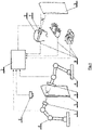
- Fig. 1 shows a schematic representation of the device according to the invention.
- Fig. 1 shows the source of radiation 1 fixed to the robotic arm 4 .
- the source 1 of radiation may be the electrically powered X-ray tube, but in other examples of embodiment of the invention, the source 1 of radiation may be, for example, the radioactive isotope, ultrasound generator, etc.
- An expert in the field of forms of penetrating energy will be able to select other alternatives for the source 1 of radiation that can be used for imaging the internal structure of the object 5 .
- the image detector 3 is arranged behind the scanning area.
- the detector 3 may consist of an array without peripheral pixel semiconductor detector units, which convert the incident radiation into the electrical charge that is subsequently converted by reading chip into an electric signal for the control unit 2 .
- the detector 3 is also carried by the robotic arm 4 .
- only one robotic arm 4 may be used, which carries both the source 1 and the detector 3 of penetrating radiation, or two or more robotic arms 4 , which are located on one side of the examined object 5 .
- It may be ultrasound, X-ray, gamma rays or another type of penetrating radiation.
- radiation reflections or scattering in the object 5 are detected or the secondary radiation (e.g. X-ray fluorescence) is detected.
- the robotic arms 4 have a fixed base and are divided into movably interconnected segments, with their mutual movability ensuring the degrees of freedom of movement in space.
- the basic position of the robotic arms 4 is optional.
- the robotic arms 4 are a catalogue item for an expert and the expert will be able to routinely select the appropriate robotic arms 4 .
- the object 5 is located in the scanning area. If the size of the object 5 is less than the size of the scanning area, the whole object 5 will be placed in the scanning area; in another unillustrated embodiment of the invention, the object 5 may be, for example, the blade of the wind power station or the wing of aircraft, which are inserted into the scanning area only partially.
- the object 5 may be self-supporting, for example, the free end of the fan blade of the wind power station, or can be placed on a suitable table for holding it in the scanning area.
- the device is provided with the tool 6 for scanning the surface of the object 5 .
- the tool 6 can be the scanner for scanning the shape of the object 5 .
- the scanner sends the scanned data to the control unit 2 , which then creates a three-dimensional virtual image of the object 5 for virtual reality.
- the scanner can be, for example, manual, or the scanning area can be fitted with stationary scanners, or the scanner can be mounted to the robotic arm 4 . Scanners obtain information on the 3D surface, for example, using a laser beam.
- optical cameras mounted on the robotic arms 4 are used instead of the scanner as the tool 6 for scanning the surface of the object 5 .
- the image of the object 5 obtained either by visualization of 3D surface, or from the camera(s), can be projected on a classical display.
- the operator 9 controls the angle of view either by changing his/her position in the virtual world, or by means of other suitable 3D actuating device 8 , e.g. 3D mouse.
- the control unit 2 is composed of a classical computer, which consists of processors for processing tasks according to SW modules, as well as operating memories, graphics cards to generate virtual reality, data repositories, motherboard with connectors, etc.
- the expert will be able to define the necessary components of a computer.
- At least one SW module is stored on the data repository for processing the input data and for the virtual image of the surface and internal structure of the object 5 in virtual reality.
- Virtual means apparent, so the virtual image is the apparent image generated electronically, which is projected as an image to the operator's 9 eyes by display or glasses 7 .
- the virtual image of the actual object 5 copies everything as if it were observation of the actual object 5 , while virtual reality allows operations that are not real in the actual world, for example, observer reduction, observer teleportation. Scanned images from classical camera are actually a virtual copy of the actual state of things.
- the operator 9 is provided with glasses 7 to produce a stereoscopic image of virtual reality directly into his/her field of vision as well as with actuating devices 8 , held by the operator 9 or fastened, for example, in gloves or to shoes, for recording the movement of his/her body.
- the actuating device 8 may comprise the microphone for scanning voice commands incorporated in glasses 7 or elsewhere within reach of sound.
- the invention works such that the virtual image of the surface of the object 5 is first created, which is made from the set of data obtained by scanning with the use of the surface scanning tool 6 . Subsequently, the operator 9 puts on glasses 7 to view in virtual reality and, for example, gloves with actuating devices 8 . The operator 9 views the displayed model and can simultaneously manipulate it by scanning the movement of hands and fingers by actuating devices 8 or can move around the object 5 if the scale of the object 5 is selected greater than the scale of the observer in virtual reality. To examine the object 5 , optical cameras mounted on the robotic arms 4 can be used instead of a three-dimensional model.
- the operator 9 may start the source 1 of radiation and the detector 3 , which start to generate data for creating the virtual image of the internal structure of the object 5 .
- the solid angle ⁇ of view of the operator's eye of the virtual image is the same as the angle ⁇ of scanning of the detector 3 against the object 5 .
- the current virtual image of the internal structure is projected into the virtual image of the surface, so the illusion is such as if the operator 9 looks with his/her eyes at the actually transparent object 5 . Any rotation of the virtual image, the angle of view of the observer or his/her distance from the object 5 in virtual reality is concurrently copied by movement of the robotic arms 4 with the detector 3 and the source 1 of radiation.
- the operator 9 can change the scale into a more detailed scale for examination of the details, or zoom out the virtual image of the object 5 to obtain an overall view.
- the virtual images of the internal structure are archived on the data repository of the control unit 2 for their repeated display or further data processing.
- Another tool of virtual reality may be the marking of the areas of interest that are automatically examined at the end of the session, for example, by means of laminography or computed tomography.
- the method of non-destructive imaging of the internal structure in a virtual reality and the device for carrying out this method according to the invention will be applied in industry and in research. For example, in non-destructive testing of newly manufactured parts or parts requiring re-inspection of their internal structures.
Landscapes
- Physics & Mathematics (AREA)
- General Physics & Mathematics (AREA)
- Health & Medical Sciences (AREA)
- Engineering & Computer Science (AREA)
- Life Sciences & Earth Sciences (AREA)
- Chemical & Material Sciences (AREA)
- Analytical Chemistry (AREA)
- Biochemistry (AREA)
- General Health & Medical Sciences (AREA)
- Immunology (AREA)
- Pathology (AREA)
- Theoretical Computer Science (AREA)
- Pulmonology (AREA)
- Radiology & Medical Imaging (AREA)
- Nuclear Medicine, Radiotherapy & Molecular Imaging (AREA)
- General Engineering & Computer Science (AREA)
- Acoustics & Sound (AREA)
- Computer Vision & Pattern Recognition (AREA)
- Computer Graphics (AREA)
- Computer Hardware Design (AREA)
- Quality & Reliability (AREA)
- Software Systems (AREA)
- Multimedia (AREA)
- Signal Processing (AREA)
- Toxicology (AREA)
- Analysing Materials By The Use Of Radiation (AREA)
- Image Processing (AREA)
- Manipulator (AREA)
- Processing Or Creating Images (AREA)
- Length Measuring Devices With Unspecified Measuring Means (AREA)
Applications Claiming Priority (2)
| Application Number | Priority Date | Filing Date | Title |
|---|---|---|---|
| CZ2017-777A CZ2017777A3 (cs) | 2017-12-05 | 2017-12-05 | Způsob nedestruktivního zobrazování vnitřní struktury a zařízení k provádění tohoto způsobu |
| PCT/CZ2018/050058 WO2019110024A1 (en) | 2017-12-05 | 2018-12-04 | Method of non-destructive imaging of the internal structure of an object and device for carrying out the method |
Publications (2)
| Publication Number | Publication Date |
|---|---|
| EP3721168A1 EP3721168A1 (en) | 2020-10-14 |
| EP3721168B1 true EP3721168B1 (en) | 2022-04-20 |
Family
ID=64959052
Family Applications (1)
| Application Number | Title | Priority Date | Filing Date |
|---|---|---|---|
| EP18830131.1A Active EP3721168B1 (en) | 2017-12-05 | 2018-12-04 | Method of non-destructive imaging of the internal structure of an object and device for carrying out the method |
Country Status (5)
| Country | Link |
|---|---|
| US (1) | US11670053B2 (cs) |
| EP (1) | EP3721168B1 (cs) |
| JP (1) | JP7315242B2 (cs) |
| CZ (1) | CZ2017777A3 (cs) |
| WO (1) | WO2019110024A1 (cs) |
Families Citing this family (13)
| Publication number | Priority date | Publication date | Assignee | Title |
|---|---|---|---|---|
| CZ2017777A3 (cs) * | 2017-12-05 | 2019-07-03 | Radalytica s.r.o. | Způsob nedestruktivního zobrazování vnitřní struktury a zařízení k provádění tohoto způsobu |
| IT201900002335A1 (it) * | 2019-02-18 | 2020-08-18 | Tiberina Solutions S R L | Sistema per la verifica della presenza di restrizioni di spessore su almeno un componente meccanico e relativo metodo di verifica |
| JP7394545B2 (ja) * | 2019-06-20 | 2023-12-08 | 株式会社小松製作所 | 非破壊検査システム、学習済みの排ガス処理フィルタ検査モデルの製造方法、および学習用データの生成方法 |
| CA3146080A1 (en) * | 2019-08-05 | 2021-02-11 | Conocophillips Company | Portable articulating ultrasonic inspection |
| US11619597B2 (en) | 2020-05-27 | 2023-04-04 | Illinois Tool Works Inc. | Dual robot control systems for non-destructive evaluation |
| EP4024034B1 (en) * | 2021-01-05 | 2025-05-28 | The Boeing Company | Methods and apparatus for measuring fastener concentricity |
| US11685005B2 (en) | 2021-02-26 | 2023-06-27 | Honda Motor Co., Ltd. | Systems and methods of repairing a stamping die |
| US11585768B1 (en) * | 2021-08-24 | 2023-02-21 | Neuf Inc. | System and method for inspecting defects of structure by using x-ray |
| US12276786B2 (en) * | 2021-12-14 | 2025-04-15 | Gm Cruise Holdings Llc | Self-illuminating distortion harp |
| JP2025501192A (ja) * | 2021-12-28 | 2025-01-17 | オーリス ヘルス インコーポレイテッド | オフスクリーンインジケータビューアユーザーインターフェース |
| CN118937279A (zh) * | 2023-05-09 | 2024-11-12 | 群创光电股份有限公司 | 电子装置的检测方法 |
| US12560562B2 (en) | 2023-09-15 | 2026-02-24 | General Electric Company | Inspection apparatus and method for inspecting a component |
| US20250319602A1 (en) * | 2024-04-14 | 2025-10-16 | Radalytica A.S. | Method of calibration of NDT systems for measurement of the internal structure of large-scale objects |
Family Cites Families (19)
| Publication number | Priority date | Publication date | Assignee | Title |
|---|---|---|---|---|
| JPH0773300A (ja) * | 1993-09-07 | 1995-03-17 | Olympus Optical Co Ltd | 超音波画像信号処理装置及び超音波画像信号処理システム |
| DE10315242B4 (de) * | 2003-04-03 | 2006-02-23 | Siemens Ag | Verfahren und Vorrichtung zur realitätsnahen dreidimensionalen Bildgebung |
| JP4143859B2 (ja) * | 2004-09-22 | 2008-09-03 | 株式会社島津製作所 | X線透視装置 |
| WO2006042211A2 (en) * | 2004-10-07 | 2006-04-20 | University Of Florida Research Foundation, Inc. | Radiographic medical imaging system using robot mounted source and sensor for dynamic image capture and tomography |
| JP4999012B2 (ja) | 2005-06-06 | 2012-08-15 | インチュイティブ サージカル,インコーポレイテッド | 腹腔鏡超音波ロボット外科手術システム |
| JP2007278995A (ja) | 2006-04-12 | 2007-10-25 | Toshiba Corp | 3次元形状測定方法および3次元形状測定装置 |
| DE102006022104B4 (de) | 2006-05-11 | 2012-09-06 | Fraunhofer-Gesellschaft zur Förderung der angewandten Forschung e.V. | Vorrichtung zur dreidimensionalen Vermessung eines Festkörpers |
| JP2010131053A (ja) | 2008-12-02 | 2010-06-17 | Konica Minolta Medical & Graphic Inc | 超音波画像診断システムおよび超音波画像診断システムを動作させるプログラム |
| US9370332B2 (en) | 2010-11-10 | 2016-06-21 | Siemens Medical Solutions Usa, Inc. | Robotic navigated nuclear probe imaging |
| US9524552B2 (en) | 2011-08-03 | 2016-12-20 | The Regents Of The University Of California | 2D/3D registration of a digital mouse atlas with X-ray projection images and optical camera photos |
| US20140286479A1 (en) * | 2011-10-11 | 2014-09-25 | Amish Chandrakant Sura | Guided Imaging System |
| US9408582B2 (en) * | 2011-10-11 | 2016-08-09 | Amish Sura | Guided imaging system |
| EP2956814A1 (en) * | 2013-02-14 | 2015-12-23 | Seiko Epson Corporation | Head mounted display and control method for head mounted display |
| KR101480968B1 (ko) | 2013-08-23 | 2015-01-14 | 한국생산기술연구원 | X-선 ct 및 레이저 표면 검사를 이용하는 검사 장치 및 검사 방법 |
| DE102014206004A1 (de) | 2014-03-31 | 2015-10-01 | Siemens Aktiengesellschaft | Triangulationsbasierte Tiefen- und Oberflächen-Visualisierung |
| GB201504360D0 (en) | 2015-03-16 | 2015-04-29 | Univ Leuven Kath | Automated quality control and selection system |
| EP3545488A1 (en) * | 2016-11-23 | 2019-10-02 | Li-Cor, Inc. | Motion-adaptive interactive imaging method |
| EP3318214B1 (en) * | 2017-04-21 | 2020-04-15 | Siemens Healthcare GmbH | Medical imaging device with smartglasses and method for supporting a person using a medical imaging device |
| CZ2017777A3 (cs) * | 2017-12-05 | 2019-07-03 | Radalytica s.r.o. | Způsob nedestruktivního zobrazování vnitřní struktury a zařízení k provádění tohoto způsobu |
-
2017
- 2017-12-05 CZ CZ2017-777A patent/CZ2017777A3/cs unknown
-
2018
- 2018-12-04 JP JP2020531010A patent/JP7315242B2/ja active Active
- 2018-12-04 US US16/769,632 patent/US11670053B2/en active Active
- 2018-12-04 WO PCT/CZ2018/050058 patent/WO2019110024A1/en not_active Ceased
- 2018-12-04 EP EP18830131.1A patent/EP3721168B1/en active Active
Also Published As
| Publication number | Publication date |
|---|---|
| JP2021506009A (ja) | 2021-02-18 |
| JP7315242B2 (ja) | 2023-07-26 |
| US11670053B2 (en) | 2023-06-06 |
| US20210072166A1 (en) | 2021-03-11 |
| WO2019110024A1 (en) | 2019-06-13 |
| CZ2017777A3 (cs) | 2019-07-03 |
| EP3721168A1 (en) | 2020-10-14 |
Similar Documents
| Publication | Publication Date | Title |
|---|---|---|
| US11670053B2 (en) | Method of non-destructive imaging of the internal structure and device for carrying out the method | |
| KR100576228B1 (ko) | 다시각 x선 입체 영상 방법 및 시스템 | |
| JP5113767B2 (ja) | 構造およびシステムの変更のための非ラインオブサイトリバースエンジニアリング | |
| JP6683206B2 (ja) | 斜めct装置 | |
| EP1999486B1 (en) | Detection device comprising a gamma imaging device, and a second imaging device which is sensitive to radiation different from gamma radiation | |
| JP6122572B2 (ja) | 可搬型検出装置用の位置感知装置 | |
| CN111031918A (zh) | X射线成像设备及其控制方法 | |
| WO2021100513A1 (ja) | 放射線撮影システム、放射線撮影方法、画像処理装置およびプログラム | |
| US12324691B2 (en) | Cone beam computed tomography centering with augmented reality | |
| JP2025120343A (ja) | 非破壊評価用の双腕型ロボット制御システム | |
| US6115449A (en) | Apparatus for quantitative stereoscopic radiography | |
| JP6153105B2 (ja) | Ct装置 | |
| JP2009294047A (ja) | X線検査装置 | |
| JP5396846B2 (ja) | X線ct装置 | |
| Sasov | Desktop x-ray micro-CT instruments | |
| JP5251264B2 (ja) | X線ct装置 | |
| Asif et al. | Advancements in 3D X-ray imaging: development and application of a twin robot system | |
| JP4385500B2 (ja) | 断層画像処理装置 | |
| JPS6314621B2 (cs) | ||
| JP4636258B2 (ja) | X線撮影装置 | |
| JP7469929B2 (ja) | 医用画像処理装置及びx線撮影装置 | |
| EP4732777A1 (en) | Controlling an x-ray radiation field on augmented live video using 3d information | |
| RU2745304C1 (ru) | Способ рентгеновской томографии и устройство для его осуществления | |
| JP2016537620A (ja) | 試験対象物とx線検査システムとの間の危険領域を決定する方法 | |
| CN209606349U (zh) | 成像装置 |
Legal Events
| Date | Code | Title | Description |
|---|---|---|---|
| STAA | Information on the status of an ep patent application or granted ep patent |
Free format text: STATUS: UNKNOWN |
|
| STAA | Information on the status of an ep patent application or granted ep patent |
Free format text: STATUS: THE INTERNATIONAL PUBLICATION HAS BEEN MADE |
|
| PUAI | Public reference made under article 153(3) epc to a published international application that has entered the european phase |
Free format text: ORIGINAL CODE: 0009012 |
|
| STAA | Information on the status of an ep patent application or granted ep patent |
Free format text: STATUS: REQUEST FOR EXAMINATION WAS MADE |
|
| 17P | Request for examination filed |
Effective date: 20200630 |
|
| AK | Designated contracting states |
Kind code of ref document: A1 Designated state(s): AL AT BE BG CH CY CZ DE DK EE ES FI FR GB GR HR HU IE IS IT LI LT LU LV MC MK MT NL NO PL PT RO RS SE SI SK SM TR |
|
| AX | Request for extension of the european patent |
Extension state: BA ME |
|
| RAP1 | Party data changed (applicant data changed or rights of an application transferred) |
Owner name: RADALYTICA A.S. |
|
| DAV | Request for validation of the european patent (deleted) | ||
| DAX | Request for extension of the european patent (deleted) | ||
| GRAP | Despatch of communication of intention to grant a patent |
Free format text: ORIGINAL CODE: EPIDOSNIGR1 |
|
| STAA | Information on the status of an ep patent application or granted ep patent |
Free format text: STATUS: GRANT OF PATENT IS INTENDED |
|
| RIC1 | Information provided on ipc code assigned before grant |
Ipc: G01N 23/02 20060101ALN20211019BHEP Ipc: G01N 29/265 20060101ALI20211019BHEP Ipc: G01N 29/06 20060101ALI20211019BHEP Ipc: G06T 19/00 20110101ALI20211019BHEP Ipc: G01B 11/24 20060101AFI20211019BHEP |
|
| INTG | Intention to grant announced |
Effective date: 20211116 |
|
| GRAS | Grant fee paid |
Free format text: ORIGINAL CODE: EPIDOSNIGR3 |
|
| GRAA | (expected) grant |
Free format text: ORIGINAL CODE: 0009210 |
|
| STAA | Information on the status of an ep patent application or granted ep patent |
Free format text: STATUS: THE PATENT HAS BEEN GRANTED |
|
| AK | Designated contracting states |
Kind code of ref document: B1 Designated state(s): AL AT BE BG CH CY CZ DE DK EE ES FI FR GB GR HR HU IE IS IT LI LT LU LV MC MK MT NL NO PL PT RO RS SE SI SK SM TR |
|
| REG | Reference to a national code |
Ref country code: GB Ref legal event code: FG4D |
|
| REG | Reference to a national code |
Ref country code: CH Ref legal event code: EP |
|
| REG | Reference to a national code |
Ref country code: DE Ref legal event code: R096 Ref document number: 602018034281 Country of ref document: DE |
|
| REG | Reference to a national code |
Ref country code: IE Ref legal event code: FG4D |
|
| REG | Reference to a national code |
Ref country code: AT Ref legal event code: REF Ref document number: 1485459 Country of ref document: AT Kind code of ref document: T Effective date: 20220515 |
|
| REG | Reference to a national code |
Ref country code: NL Ref legal event code: FP |
|
| REG | Reference to a national code |
Ref country code: LT Ref legal event code: MG9D |
|
| REG | Reference to a national code |
Ref country code: AT Ref legal event code: MK05 Ref document number: 1485459 Country of ref document: AT Kind code of ref document: T Effective date: 20220420 |
|
| PG25 | Lapsed in a contracting state [announced via postgrant information from national office to epo] |
Ref country code: SE Free format text: LAPSE BECAUSE OF FAILURE TO SUBMIT A TRANSLATION OF THE DESCRIPTION OR TO PAY THE FEE WITHIN THE PRESCRIBED TIME-LIMIT Effective date: 20220420 Ref country code: PT Free format text: LAPSE BECAUSE OF FAILURE TO SUBMIT A TRANSLATION OF THE DESCRIPTION OR TO PAY THE FEE WITHIN THE PRESCRIBED TIME-LIMIT Effective date: 20220822 Ref country code: NO Free format text: LAPSE BECAUSE OF FAILURE TO SUBMIT A TRANSLATION OF THE DESCRIPTION OR TO PAY THE FEE WITHIN THE PRESCRIBED TIME-LIMIT Effective date: 20220720 Ref country code: LT Free format text: LAPSE BECAUSE OF FAILURE TO SUBMIT A TRANSLATION OF THE DESCRIPTION OR TO PAY THE FEE WITHIN THE PRESCRIBED TIME-LIMIT Effective date: 20220420 Ref country code: HR Free format text: LAPSE BECAUSE OF FAILURE TO SUBMIT A TRANSLATION OF THE DESCRIPTION OR TO PAY THE FEE WITHIN THE PRESCRIBED TIME-LIMIT Effective date: 20220420 Ref country code: GR Free format text: LAPSE BECAUSE OF FAILURE TO SUBMIT A TRANSLATION OF THE DESCRIPTION OR TO PAY THE FEE WITHIN THE PRESCRIBED TIME-LIMIT Effective date: 20220721 Ref country code: FI Free format text: LAPSE BECAUSE OF FAILURE TO SUBMIT A TRANSLATION OF THE DESCRIPTION OR TO PAY THE FEE WITHIN THE PRESCRIBED TIME-LIMIT Effective date: 20220420 Ref country code: ES Free format text: LAPSE BECAUSE OF FAILURE TO SUBMIT A TRANSLATION OF THE DESCRIPTION OR TO PAY THE FEE WITHIN THE PRESCRIBED TIME-LIMIT Effective date: 20220420 Ref country code: BG Free format text: LAPSE BECAUSE OF FAILURE TO SUBMIT A TRANSLATION OF THE DESCRIPTION OR TO PAY THE FEE WITHIN THE PRESCRIBED TIME-LIMIT Effective date: 20220720 Ref country code: AT Free format text: LAPSE BECAUSE OF FAILURE TO SUBMIT A TRANSLATION OF THE DESCRIPTION OR TO PAY THE FEE WITHIN THE PRESCRIBED TIME-LIMIT Effective date: 20220420 |
|
| PG25 | Lapsed in a contracting state [announced via postgrant information from national office to epo] |
Ref country code: RS Free format text: LAPSE BECAUSE OF FAILURE TO SUBMIT A TRANSLATION OF THE DESCRIPTION OR TO PAY THE FEE WITHIN THE PRESCRIBED TIME-LIMIT Effective date: 20220420 Ref country code: PL Free format text: LAPSE BECAUSE OF FAILURE TO SUBMIT A TRANSLATION OF THE DESCRIPTION OR TO PAY THE FEE WITHIN THE PRESCRIBED TIME-LIMIT Effective date: 20220420 Ref country code: LV Free format text: LAPSE BECAUSE OF FAILURE TO SUBMIT A TRANSLATION OF THE DESCRIPTION OR TO PAY THE FEE WITHIN THE PRESCRIBED TIME-LIMIT Effective date: 20220420 Ref country code: IS Free format text: LAPSE BECAUSE OF FAILURE TO SUBMIT A TRANSLATION OF THE DESCRIPTION OR TO PAY THE FEE WITHIN THE PRESCRIBED TIME-LIMIT Effective date: 20220820 |
|
| REG | Reference to a national code |
Ref country code: DE Ref legal event code: R097 Ref document number: 602018034281 Country of ref document: DE |
|
| PG25 | Lapsed in a contracting state [announced via postgrant information from national office to epo] |
Ref country code: SM Free format text: LAPSE BECAUSE OF FAILURE TO SUBMIT A TRANSLATION OF THE DESCRIPTION OR TO PAY THE FEE WITHIN THE PRESCRIBED TIME-LIMIT Effective date: 20220420 Ref country code: SK Free format text: LAPSE BECAUSE OF FAILURE TO SUBMIT A TRANSLATION OF THE DESCRIPTION OR TO PAY THE FEE WITHIN THE PRESCRIBED TIME-LIMIT Effective date: 20220420 Ref country code: RO Free format text: LAPSE BECAUSE OF FAILURE TO SUBMIT A TRANSLATION OF THE DESCRIPTION OR TO PAY THE FEE WITHIN THE PRESCRIBED TIME-LIMIT Effective date: 20220420 Ref country code: EE Free format text: LAPSE BECAUSE OF FAILURE TO SUBMIT A TRANSLATION OF THE DESCRIPTION OR TO PAY THE FEE WITHIN THE PRESCRIBED TIME-LIMIT Effective date: 20220420 Ref country code: DK Free format text: LAPSE BECAUSE OF FAILURE TO SUBMIT A TRANSLATION OF THE DESCRIPTION OR TO PAY THE FEE WITHIN THE PRESCRIBED TIME-LIMIT Effective date: 20220420 |
|
| PLBE | No opposition filed within time limit |
Free format text: ORIGINAL CODE: 0009261 |
|
| STAA | Information on the status of an ep patent application or granted ep patent |
Free format text: STATUS: NO OPPOSITION FILED WITHIN TIME LIMIT |
|
| 26N | No opposition filed |
Effective date: 20230123 |
|
| PG25 | Lapsed in a contracting state [announced via postgrant information from national office to epo] |
Ref country code: AL Free format text: LAPSE BECAUSE OF FAILURE TO SUBMIT A TRANSLATION OF THE DESCRIPTION OR TO PAY THE FEE WITHIN THE PRESCRIBED TIME-LIMIT Effective date: 20220420 |
|
| PG25 | Lapsed in a contracting state [announced via postgrant information from national office to epo] |
Ref country code: SI Free format text: LAPSE BECAUSE OF FAILURE TO SUBMIT A TRANSLATION OF THE DESCRIPTION OR TO PAY THE FEE WITHIN THE PRESCRIBED TIME-LIMIT Effective date: 20220420 |
|
| PG25 | Lapsed in a contracting state [announced via postgrant information from national office to epo] |
Ref country code: CZ Free format text: LAPSE BECAUSE OF NON-PAYMENT OF DUE FEES Effective date: 20221204 |
|
| REG | Reference to a national code |
Ref country code: BE Ref legal event code: MM Effective date: 20221231 |
|
| PG25 | Lapsed in a contracting state [announced via postgrant information from national office to epo] |
Ref country code: LU Free format text: LAPSE BECAUSE OF NON-PAYMENT OF DUE FEES Effective date: 20221204 |
|
| PG25 | Lapsed in a contracting state [announced via postgrant information from national office to epo] |
Ref country code: IE Free format text: LAPSE BECAUSE OF NON-PAYMENT OF DUE FEES Effective date: 20221204 |
|
| PG25 | Lapsed in a contracting state [announced via postgrant information from national office to epo] |
Ref country code: BE Free format text: LAPSE BECAUSE OF NON-PAYMENT OF DUE FEES Effective date: 20221231 |
|
| PGFP | Annual fee paid to national office [announced via postgrant information from national office to epo] |
Ref country code: NL Payment date: 20231108 Year of fee payment: 6 |
|
| PGFP | Annual fee paid to national office [announced via postgrant information from national office to epo] |
Ref country code: GB Payment date: 20231107 Year of fee payment: 6 |
|
| PG25 | Lapsed in a contracting state [announced via postgrant information from national office to epo] |
Ref country code: IT Free format text: LAPSE BECAUSE OF FAILURE TO SUBMIT A TRANSLATION OF THE DESCRIPTION OR TO PAY THE FEE WITHIN THE PRESCRIBED TIME-LIMIT Effective date: 20220420 |
|
| PGFP | Annual fee paid to national office [announced via postgrant information from national office to epo] |
Ref country code: FR Payment date: 20231107 Year of fee payment: 6 Ref country code: DE Payment date: 20231108 Year of fee payment: 6 |
|
| PG25 | Lapsed in a contracting state [announced via postgrant information from national office to epo] |
Ref country code: CY Free format text: LAPSE BECAUSE OF FAILURE TO SUBMIT A TRANSLATION OF THE DESCRIPTION OR TO PAY THE FEE WITHIN THE PRESCRIBED TIME-LIMIT Effective date: 20220420 |
|
| PGFP | Annual fee paid to national office [announced via postgrant information from national office to epo] |
Ref country code: CH Payment date: 20240102 Year of fee payment: 6 |
|
| PG25 | Lapsed in a contracting state [announced via postgrant information from national office to epo] |
Ref country code: MK Free format text: LAPSE BECAUSE OF FAILURE TO SUBMIT A TRANSLATION OF THE DESCRIPTION OR TO PAY THE FEE WITHIN THE PRESCRIBED TIME-LIMIT Effective date: 20220420 Ref country code: HU Free format text: LAPSE BECAUSE OF FAILURE TO SUBMIT A TRANSLATION OF THE DESCRIPTION OR TO PAY THE FEE WITHIN THE PRESCRIBED TIME-LIMIT; INVALID AB INITIO Effective date: 20181204 |
|
| PG25 | Lapsed in a contracting state [announced via postgrant information from national office to epo] |
Ref country code: MC Free format text: LAPSE BECAUSE OF FAILURE TO SUBMIT A TRANSLATION OF THE DESCRIPTION OR TO PAY THE FEE WITHIN THE PRESCRIBED TIME-LIMIT Effective date: 20220420 |
|
| PG25 | Lapsed in a contracting state [announced via postgrant information from national office to epo] |
Ref country code: MC Free format text: LAPSE BECAUSE OF FAILURE TO SUBMIT A TRANSLATION OF THE DESCRIPTION OR TO PAY THE FEE WITHIN THE PRESCRIBED TIME-LIMIT Effective date: 20220420 |
|
| PG25 | Lapsed in a contracting state [announced via postgrant information from national office to epo] |
Ref country code: MT Free format text: LAPSE BECAUSE OF FAILURE TO SUBMIT A TRANSLATION OF THE DESCRIPTION OR TO PAY THE FEE WITHIN THE PRESCRIBED TIME-LIMIT Effective date: 20220420 |
|
| PG25 | Lapsed in a contracting state [announced via postgrant information from national office to epo] |
Ref country code: BG Free format text: LAPSE BECAUSE OF FAILURE TO SUBMIT A TRANSLATION OF THE DESCRIPTION OR TO PAY THE FEE WITHIN THE PRESCRIBED TIME-LIMIT Effective date: 20220420 |
|
| PG25 | Lapsed in a contracting state [announced via postgrant information from national office to epo] |
Ref country code: BG Free format text: LAPSE BECAUSE OF FAILURE TO SUBMIT A TRANSLATION OF THE DESCRIPTION OR TO PAY THE FEE WITHIN THE PRESCRIBED TIME-LIMIT Effective date: 20220420 |
|
| REG | Reference to a national code |
Ref country code: DE Ref legal event code: R119 Ref document number: 602018034281 Country of ref document: DE |
|
| REG | Reference to a national code |
Ref country code: CH Ref legal event code: PL |
|
| REG | Reference to a national code |
Ref country code: NL Ref legal event code: MM Effective date: 20250101 |
|
| GBPC | Gb: european patent ceased through non-payment of renewal fee |
Effective date: 20241204 |
|
| PG25 | Lapsed in a contracting state [announced via postgrant information from national office to epo] |
Ref country code: NL Free format text: LAPSE BECAUSE OF NON-PAYMENT OF DUE FEES Effective date: 20250101 |
|
| PG25 | Lapsed in a contracting state [announced via postgrant information from national office to epo] |
Ref country code: DE Free format text: LAPSE BECAUSE OF NON-PAYMENT OF DUE FEES Effective date: 20250701 |
|
| PG25 | Lapsed in a contracting state [announced via postgrant information from national office to epo] |
Ref country code: GB Free format text: LAPSE BECAUSE OF NON-PAYMENT OF DUE FEES Effective date: 20241204 |
|
| PG25 | Lapsed in a contracting state [announced via postgrant information from national office to epo] |
Ref country code: FR Free format text: LAPSE BECAUSE OF NON-PAYMENT OF DUE FEES Effective date: 20241231 |
|
| PG25 | Lapsed in a contracting state [announced via postgrant information from national office to epo] |
Ref country code: CH Free format text: LAPSE BECAUSE OF NON-PAYMENT OF DUE FEES Effective date: 20241231 |
|
| PG25 | Lapsed in a contracting state [announced via postgrant information from national office to epo] |
Ref country code: TR Free format text: LAPSE BECAUSE OF FAILURE TO SUBMIT A TRANSLATION OF THE DESCRIPTION OR TO PAY THE FEE WITHIN THE PRESCRIBED TIME-LIMIT Effective date: 20220420 |