EP3721174B1 - Wegaufnehmervorrichtung - Google Patents
Wegaufnehmervorrichtung Download PDFInfo
- Publication number
- EP3721174B1 EP3721174B1 EP18829492.0A EP18829492A EP3721174B1 EP 3721174 B1 EP3721174 B1 EP 3721174B1 EP 18829492 A EP18829492 A EP 18829492A EP 3721174 B1 EP3721174 B1 EP 3721174B1
- Authority
- EP
- European Patent Office
- Prior art keywords
- magnet
- transducer
- reference point
- magnets
- transducer device
- Prior art date
- Legal status (The legal status is an assumption and is not a legal conclusion. Google has not performed a legal analysis and makes no representation as to the accuracy of the status listed.)
- Active
Links
Images
Classifications
-
- G—PHYSICS
- G01—MEASURING; TESTING
- G01D—MEASURING NOT SPECIALLY ADAPTED FOR A SPECIFIC VARIABLE; ARRANGEMENTS FOR MEASURING TWO OR MORE VARIABLES NOT COVERED IN A SINGLE OTHER SUBCLASS; TARIFF METERING APPARATUS; MEASURING OR TESTING NOT OTHERWISE PROVIDED FOR
- G01D5/00—Mechanical means for transferring the output of a sensing member; Means for converting the output of a sensing member to another variable where the form or nature of the sensing member does not constrain the means for converting; Transducers not specially adapted for a specific variable
- G01D5/12—Mechanical means for transferring the output of a sensing member; Means for converting the output of a sensing member to another variable where the form or nature of the sensing member does not constrain the means for converting; Transducers not specially adapted for a specific variable using electric or magnetic means
- G01D5/14—Mechanical means for transferring the output of a sensing member; Means for converting the output of a sensing member to another variable where the form or nature of the sensing member does not constrain the means for converting; Transducers not specially adapted for a specific variable using electric or magnetic means influencing the magnitude of a current or voltage
- G01D5/142—Mechanical means for transferring the output of a sensing member; Means for converting the output of a sensing member to another variable where the form or nature of the sensing member does not constrain the means for converting; Transducers not specially adapted for a specific variable using electric or magnetic means influencing the magnitude of a current or voltage using Hall-effect devices
- G01D5/145—Mechanical means for transferring the output of a sensing member; Means for converting the output of a sensing member to another variable where the form or nature of the sensing member does not constrain the means for converting; Transducers not specially adapted for a specific variable using electric or magnetic means influencing the magnitude of a current or voltage using Hall-effect devices influenced by the relative movement between the Hall device and magnetic fields
-
- G—PHYSICS
- G01—MEASURING; TESTING
- G01D—MEASURING NOT SPECIALLY ADAPTED FOR A SPECIFIC VARIABLE; ARRANGEMENTS FOR MEASURING TWO OR MORE VARIABLES NOT COVERED IN A SINGLE OTHER SUBCLASS; TARIFF METERING APPARATUS; MEASURING OR TESTING NOT OTHERWISE PROVIDED FOR
- G01D2205/00—Indexing scheme relating to details of means for transferring or converting the output of a sensing member
- G01D2205/80—Manufacturing details of magnetic targets for magnetic encoders
Definitions
- the present invention relates to a movement transducer device and to an associated method of use having the features set out in the preambles of the independent claims.
- linear inductive displacement transducers linear variable displacement transducers - LVDTs
- linear inductive displacement transducers linear variable displacement transducers - LVDTs
- this limitation actually derives from the specific geometric configuration of the device and in particular from the coaxial arrangement of a movable element comprising the ferromagnetic element with respect to three circular windings within which the ferromagnetic element runs.
- a further drawback is the need to use complex signals having a sinusoidal progression so as to be able correctly to set or correct the displacement values detected by the linear inductive displacement transducer device.
- instrumentation which comprises a simpler internal structure than a plurality of coaxial toroidal windings in the centre of which a ferromagnetic element runs linearly, which is in turn connected to a movable element connected to a portion of the structure in question.
- DE 3809887 describes a system for detecting accelerations and displacements by way of a device comprising magnets arranged in a repulsive configuration and a transducer placed in proximity to said magnets.
- This device detects accelerations of movable elements which are damped by the repulsive magnetic forces of the device itself, thus countering and minimising the displacements which can take place.
- said device thus does not make it possible to monitor a development of displacements of portions of a structure in question completely, much less over time.
- US 2011/248705 e discloses a stroke amount detecting device employed to detect the stroke amount of a stroking member, such as a transmission, an acceleration pedal, or a brake pedal of a vehicle.
- the stroke amount detecting device includes a first magnetic field generation member, a second magnetic field generation member and a magnetic sensor unit.
- the second magnetic field generation member opposed to the first magnetic field generation member with respect to a direction perpendicular to a straight stroking axis along which an object strokes.
- the second magnetic field generation member and the first magnetic field generation member are magnetized in opposite directions with respect to a direction perpendicular to the stroking axis.
- the magnetic sensor unit is movable in an area between the first magnetic field generation member and the second magnetic field generation member, along a straight traveling axis that is parallel to the straight stroking axis, relative to the first magnetic field generation member and the second magnetic field generation member in accordance with a stroke motion of the object.
- WO 2014/060986 A1 discloses a measurement system of the relative position between two separate structural parts of a building or a masonry work that have separated following the formation of a crack.
- the object of the present invention is to provide a displacement transducer device which is structurally and functionally designed to overcome at least in part one or more of the identified drawbacks of the prior art.
- one aim of the invention is to make it possible to detect and monitor the development of any displacements of different portions of a structure in question.
- the finding implemented by the present invention is a displacement transducer device according to claim 1.
- first and the second reference point identify portions of the structure in question different from one another and having the potential to move independently of one another.
- housing, for example, the first and the second magnet on the first element and the transducer on the second element has the beneficial technical advantage of being able to evaluate the relative displacements between the two reference points as a function of the deformations which take place in the structure.
- the two reference points of the structure may move in similar, opposite, independent etc. displacement directions or displacement amounts. This advantage cannot be obtained using the solutions provided in the state of the art.
- the device does not provide an automatic return to an initial equilibrium situation; rather, the purpose of the finding implemented by the present invention is to evaluate over time what the development is of the relative displacements of the corresponding first reference point with respect to the second.
- a practical example which should be clear is the application of the present device to a crack.
- An advantageous way of applying a technical solution implemented in accordance with the present invention provides connecting, for example, the first magnet and the second magnet to the corresponding first reference point and the transducer to the second reference point, and the first and second reference points being identified at positions which are opposite with respect to the crack under examination (in other words, one being linked to one side and the other to the opposite side of the crack or fissure). In this way, it will be possible constantly to monitor the development over time of the crack by evaluating the relative displacement of the two sides by way of the movements of the respective reference points.
- the finding implemented by the present invention makes it possible, for example, to obtain a resolution of 150 nanometres on a 4 millimetre scale basis and thus to detect small but significant displacements for the purpose of evaluating the safety condition of the structure in question and the possible developments thereof over time.
- the finding implemented by the present invention is easily scalable as required by adapting the sizing of the magnets as a function of the extent of the displacements which it is desired to monitor.
- the present finding is scalable within a wide range of measurements of displacements simply by modifying the dimensions and types of materials concordantly as a function of the desired scale whilst maintaining the same accuracy with a relative error of 3%.
- the output signal of the finding implemented by the present invention is an analogue signal directly and linearly proportional to the variable which it is desired to measure (the relative displacement of two reference points). This condition makes it possible to have increased simplicity of operation together with precision and reliability of measurement.
- the transducer is arranged between the first magnet and the second magnet.
- the first and second magnets are permanent magnets.
- This technical solution makes it possible to benefit from simplification of the device, which is achieved as a result of the fact that the permanent magnets do not require electrical connections to generate the magnetic field and are rather light and thus easy to transport and to assemble.
- the transducer device is a magnetoresistive, magnetoinductive or similar sensor.
- the transducer device is a Hall effect sensor.
- the transducer device is a Hall effect sensor.
- the transducer is a monoaxial, biaxial or triaxial Hall effect sensor.
- the transducer comprises three monoaxial Hall effect sensors oriented, for example, along a set of three Cartesian axes in space.
- this transducer comprises a preferably monoaxial Hall effect sensor and a monoaxial, biaxial or triaxial inclinometer connected thereto so as to provide data relating to inclinations of the system along the analysed axes in addition to the data of the monoaxial Hall effect sensor relating to the aforementioned relative displacements.
- the sensitivity of the transducer device according to the present invention is identical both for displacements in a specific direction in a positive sense and for displacements in the opposite sense.
- the sensitivity of the transducer device is identical both for positive and for negative displacements (or deformations), whilst the solutions present in the state of the art have different behaviours for compression and extension of the device.
- the embodiment comprising the multiaxial (for example triaxial) transducer makes it possible to calibrate the instrumentation in a simple and highly precise manner. It is thus not necessary to carry out calibration using external instrumentation which, in addition to requiring further resources necessary for correct operation, does not make it possible to guarantee correct evaluation and analysis of the data if any displacement of the transducer or of a portion thereof occurs, for example with respect to a vertical reference axis.
- the combination of the axial displacements detected using the relative inclinations makes it possible to obtain information in terms of deformation of the structure under examination or of the fissure as a function of time and thus also of any development in the propagation thereof.
- the transducer device comprises a humidity sensor and/or a temperature sensor.
- the transducer device comprises a first spacer integrally arranged between the first reference point and the first element and a second spacer integrally arranged between the second reference point and the second element, first and second element being slab-shaped and each being connected by means of a first end to said first and second spacer, respectively.
- the first and the second magnet are housed spaced apart on said first element whilst the transducer is housed on the second element so as to be arranged between the two magnets during the initial installation and monitoring phase.
- the embodiments described above make it possible, in terms for example of studying the development and propagation of cracks, to position the device "astride" a fissure.
- the term "astride” a fissure indicates the possibility of positioning the first element integrally constrained to the corresponding first reference point (for example on a surface delimited by one side of the crack/fissure) and the second element integrally constrained to the second reference point (for example on a surface delimited by the opposite side of the crack/fissure).
- this solution is not only effective for readings of forces applied to the structure under examination which are of an impulse type, and which thus produce large relative displacements in a short time, but above all also effective for obtaining information relating to two specific reference points of a structure which move with respect to one another over long periods (for example days, weeks, months, years etc.).
- the first and second magnets are cylindrical or prism-shaped and have a first and second flat base, respectively, which face one another, the first base matches the main surface of the first element, a base opposite the second base of the second magnet matches a respective main surface of the second element, a first longitudinal axis passes through the respective centres of mass of the first and second magnet, and the first and second magnets are respectively connected to second free ends, which are opposite the first ends, of the first and second element such that the displacements of the first and second magnet or of the transducer caused by displacements of the first or second reference point are perpendicular to the first longitudinal axis, the first longitudinal axis being perpendicular to a straight line which passes through the first and second reference point.
- the first longitudinal axis passing through the respective centres of mass of the first and second magnet is substantially perpendicular to the primary extension of the fissure and simultaneously substantially perpendicular to the straight line passing through the first and second reference point.
- a plane perpendicular to the longitudinal axis of potential displacements of the first and second magnet or of the transducer is defined in which the magnets translate freely without the possibility of coming into contact or colliding within one another after planar translations of the surface portions of the structure in question.
- the transducer optimally detects variations in the magnetic field between the first and the second magnet linked to displacements of the reference points along vectors belonging to the perpendicular plane on said longitudinal axis.
- three pairs of first and second magnets are provided, each pair being positioned in a repulsive magnetic configuration, along three mutually orthogonal longitudinal axes.
- a triaxial transducer device is implemented which is suitable for detecting separately the individual displacement components for each of the three orthogonal axes thus defined.
- the transducer device preferably comprises a first pair of first and second magnets, a second pair of first and second magnets, a third pair of first and second magnets, respectively carrying a first transducer, a second transducer and a third transducer arranged between said pairs of magnets.
- the longitudinal axis of the first pair of the first and second magnets is perpendicular both to the straight line passing through the first and second reference point and to the primary extension of the fissure, when present on a surface of a structure in question;
- the second longitudinal axis of the second pair of the first and second magnets is parallel to the straight line passing through the first and second reference point and perpendicular to the primary extension of the fissure, when present.
- the third longitudinal axis of the third pair of the first and second magnets is perpendicular to the straight line passing through the first and second reference point and parallel to the primary extension of the fissure, when present.
- a triaxial transducer device which is capable of separately detecting the individual displacement components for each of the three mutually perpendicular axes thus defined.
- the first and second magnet are cylindrical or prism-shaped, and have a first and second flat base respectively, that face one another, the first base is oriented perpendicularly to the main surface of the first element, the second base is oriented perpendicularly to the respective main surface of the second element, and a second longitudinal axis passes through the respective centres of mass of said first and second magnet.
- the first and second magnet are prism-shaped.
- the first and second magnets are respectively connected to second free ends, which are opposite the first ends, of the first and second elements such that the displacements of the first and second magnet or of the transducer caused by relative displacements of the first or second reference point are parallel to the second longitudinal axis, the second longitudinal axis thus being perpendicular to a straight line which passes through the first and second reference points.
- the first and second magnet are cylindrical or prism-shaped, have a first and second flat base, respectively, which face one another, and are integrally constrained to the first element, and the transducer is connected to the second element.
- the transducer which can move independently of the first and second magnet, detecting a highly linear progression of the variation in the magnetic field.
- the method of the present invention comprises the operative steps set out hereinafter.
- the method for detecting the displacements between two reference points of the structure comprises:
- the processing unit is operatively connected to further processing units via communications means such as USB connections, uSD card, BTLE, LoRa, Cloud etc.
- the processing unit is capable of reading the signals of the transducer, storing them locally, and sending or transferring them to a host computer or to a cloud system using said USB, uSD card, BTLE, LoRa etc. means of communiation.
- the processing unit it removable from said transducer device.
- an alert message is sent via communications means operatively connected to the processing unit when the value of the relative displacements of the first and second reference point reaches or exceeds a predefined threshold value.
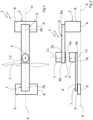
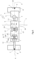
- 1 denotes as a whole a displacement transducer device which can be coupled to reference points of a structure comprising a first element 6, intended to be integrally secured to a corresponding first reference point A of the structure, and a first magnet 3; 23; 33 and a second magnet 4; 24; 34 arranged so as to magnetically repel one another, in other words having identical poles on mutually facing surfaces.
- the repulsive magnetic configuration thus provides that the two magnets are arranged having two identical poles, for example N and N as shown in Fig. 2 , facing one another. In this way, a repulsive magnetic force is implemented between the two magnets.
- This repulsive magnetic configuration makes it possible to implement a zone of highly linear magnetic behaviour in a vicinity between the positions of the first and second magnet 3, 4; 23, 24; 33, 34.
- This particular linear zone makes it possible precisely to correlate magnetic variations with relative displacements of the first and second magnet 3, 4; 23, 24; 33, 34 or of the transducer 5; 25; 35.
- the Applicant has verified that the equation of the magnetic field relating to the first and second magnet 3, 4; 23, 24; 33, 34 is not linear.
- the equations relating to the total magnetic field B Tot for a pair of cylindrical magnets arranged with the primary axes aligned and in a repulsive magnetic configuration (for example with the respective N poles facing one another) are set out below.
- B Tot B M 1 + B M 2
- B M1 is the magnetic field produced by the first magnet 3 and B M2 is the magnetic field produced by the second magnet 4
- B M 1 B R / 2 ⁇ + z R 2 + ⁇ + z 2 ⁇ z R 2 + z 2
- B M 2 ⁇ B R / 2 ⁇ + d ⁇ z R 2 + ⁇ + d ⁇ z 2 ⁇ d ⁇ z R 2 + d ⁇ z 2
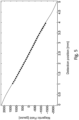
- FIG. 5 the progression of a magnetic field between +2000 and -2000 gauss, created by two magnets positioned at a fixed distance of 5 mm, as a function of the detection position between the first and second magnet 3, 4; 23, 24; 33, 34 in an interval of between 0 and 5 mm, is shown by way of example in a non-limiting manner.
- the first and second magnet 3, 4; 23, 24; 33, 34 are advantageously natural, sintered or electromagnetic magnets.
- a transducer 5; 25; 35 is placed in proximity to the first and second magnet 3, 4; 23, 24; 33, 34 and configured so as to detect a variation in the magnetic field present between the first and second magnet 3, 4; 23, 24; 33, 34 and to transform it into a signal which can be processed by a processing unit (not shown in the drawings).
- the displacement transducer device 1 comprises a second element 7 intended to be integrally fixed to a second reference point B of the structure, one of the first magnet 3; 23; 33, second magnet 4; 24; 34 and transducer 5; 25; 35 being connected to the first element 6 and the remaining elements of the first magnet 3; 23; 33 second magnet 4; 24; 34 or transducer 5; 25; 35 being connected to the second element 7 in such a way that a relative displacement of the first reference point A or of the second reference point B includes a variation in the magnetic field detectable by the transducer 5.
- the transducer 5; 25; 35 is capable of providing an electrical, optical or similar signal which can be processed by the processing unit.
- the first and the second reference point A and B are adjacent points on a continuous, uniform surface of a structure in question, or else may also be points of a structure which are separated by fissures, subsidences, defects of varying nature etc.
- the first element 6 is comprised in a housing 2 which also comprises any further electronic devices connected to the transducer 5; 25; 35.
- the first element 6, the second element 7 and/or the housing 2 are formed of diamagnetic or nonmagnetic material, for example ceramics, such as alumina, metals, such as austenitic stainless steel (having linear thermal expansion coefficients similar or near to those of the concretes or cements with which the structures in question are typically implemented) or brasses, or polymers such as polyvinyl chloride, polymer matrix composites (FR4) or the like.
- ceramics such as alumina
- metals such as austenitic stainless steel (having linear thermal expansion coefficients similar or near to those of the concretes or cements with which the structures in question are typically implemented) or brasses
- polymers such as polyvinyl chloride, polymer matrix composites (FR4) or the like.
- the housing 2 comprises extensions which integrally connect the first element 6 to the second element 7. Also preferably, two through-holes 18, 19 are formed on the first and second element 6, 7 at the first and second reference point A, B respectively of the structure in question.
- This technical solution makes it possible to position the transducer device 1 on the surface of the structure in question, rapidly to identify the reference points in a simple manner, to connect said transducer device 1 precisely, for example by way of screws or nails passing through said two holes 18, 19, to the surface of the structure in question, and subsequently to remove the extensions interconnecting the first and second element 6, 7, rendering them free to move independently.
- these extensions are formed of ceramic, metal or preferably polymer (for example PVC) material, thus being easy to shear or remove using similar processing techniques.
- the transducer 5 is positioned between the first magnet 3 and the second magnet 4.
- the transducer 5 is connected to one face of the first element 6 opposite the face intended to connect the first magnet 3.
- the first and second magnet 3, 4; 23, 24; 33, 34 are permanent magnets.
- the first and the second magnet 3, 4; 23, 24; 33, 34 are systems including iron, nickel, cobalt or alloys of rare earths or else natural minerals such as magnetite. More preferably, permanent sintered ferrite or neodymium magnets are used.
- the transducer 5; 25; 35 is a Hall effect sensor.
- the Hall effect sensor makes it possible to transform variations in the magnetic field into variations in the electrical current detected by the device itself. In this way, it is thus possible precisely to measure very small variations in the magnetic field between the first and second magnet 3, 4; 23, 24; 33, 34 and detected by the transducer 5; 25; 35 and thus to be able to calculate the corresponding relative displacement of the first reference point A with respect to the second reference point B with a sensitivity for example of 150 nanometres on a 4 millimetre scale basis. As set out above, this measurement can easily be scaled as required as a result of the technical features of the present finding.
- the transducer device 1 comprises a first spacer 8 integrally arranged between the first reference point A and the first element 6 and a second spacer 9 integrally arranged between the second reference point B and the second element 7, the first and second element 6, 7 being slab-shaped and each of them being connected at a first end 6a, 7a respectively to the first and second spacer 8, 9.
- the first element 6, the second element 7, the first spacer 8 and the second spacer 9 are formed of plastics materials or plastics matrix composite materials which are simple to produce and process using industrial technologies known in the art in the sector.
- the fixed parts which make up the transducer device 1 are connected to one another and/or to the surface of the structure in question by way of holding means such as bonding, screws etc.
- the first element 6 may preferably be connected to the second element 7 by way of a slide which makes relative translation thereof possible.
- a first pair of the first and second magnet 3, 4 is identified, the first and second magnet 3, 4 being cylindrical or prism-shaped and having a first and second flat base 3a, 4a, respectively, which face one another.
- the first and second magnet 3, 4 being cylindrical or prism-shaped and having a first and second flat base 3a, 4a, respectively, which face one another.
- the first base 3a is in abutment with the larger surface of the first element 6, a base 4b opposite the second base 4a of said second magnet 4 is in abutment with the larger surface of the second element 7, a first longitudinal axis L1 passing through the respective centres of mass of the first and second magnet 3, 4, the first and second magnet 3, 4 are respectively connected to second free ends 6b, 7b, opposite the first ends 6a, 7a, of the first and second element 6, 7 in such a way that the displacements of the first and second magnet 3, 4 or of the transducer 5 brought about by displacements of the first or second reference point A, B are perpendicular to the first longitudinal axis L1, which is thus the first longitudinal axis L1 perpendicular to a straight line X passing through the first and second reference point A, B.
- the first longitudinal axis L1 passing through the respective centres of mass of the first and second magnet 3, 4 is substantially perpendicular to the primary extension of the fissure F and simultaneously substantially perpendicular to the straight line X passing through the first and second reference point A, B.
- the first and second element 6, 7 are positioned on opposite sides of said fissure F.
- the vectors of the possible displacements of the first and second magnet 3, 4 belong to a plane perpendicular to the longitudinal axis L.
- the transducer 5 optimally detects variations in the magnetic field between the first and second magnet 3, 4 linked to displacements of the reference points along vectors belonging to the plane perpendicular to said longitudinal axis L.
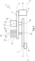
- the first and second magnet 23, 24 are cylindrical or prism-shaped and have respective first and second flat bases 23a, 24a which face one another, the first base 23a is orientated perpendicular to the larger surface of the first element 6, the second base 24a is orientated perpendicular to the larger surface of the first element 6 or of the second element 7, a second longitudinal axis L2 passes through the respective centres of mass of the first and second magnet 23, 24, and the first and second magnet 23, 24 are respectively connected to or near to second free ends 6b, 7b, opposite the first ends 6a, 7a, of the first and second element 6, 7, in such a way that the displacements of the first and second magnet 23, 24 or of the transducer 25 brought about by displacements of the first or second reference point A, B are parallel to the second longitudinal axis L2, said second longitudinal axis L2 being parallel to the X passing through the first and second reference point A, B.
- the first and second magnet 23, 24 are cylindrical or prism-shaped and have respective first and second flat bases 23a, 24a which face one another, the first base 23a and the second base 24a are orientated perpendicular to the larger surface of the first element 6, a second longitudinal axis L2 passes through the respective centres of mass of the first and second magnet 23, 24, the first and second magnet 23, 24 are respectively connected to or near to said second free end 6b, opposite the first end 6a, of the first element 6 and the transducer 25 is connected near to a second free end 7b of the second element 7 and arranged between the first and second magnet 23, 24, in such a way that the displacements of the first and second magnet 23, 24 or of the transducer 25 which are brought about by displacements of the first or second reference point A, B are parallel to the second longitudinal axis L2, said second longitudinal axis L2 being parallel to the straight line X passing through the first and second reference point A, B.
- the variation in the magnetic field between the first and second magnet 23, 24 is not given by a physical relative displacement of the two magnets but rather by a displacement of the transducer 25 with respect to said first and second magnet 23, 24.
- the Applicant has verified that, for example, some embodiments, which provide that the variation in the magnetic field between the first and the second magnet 23, 24 is not given by a physical relative displacement of the two magnets but rather by a displacement of the transducer 25 with respect to said first and second magnet 23, 24, make it possible to obtain a more extensive zone of linearity of the total magnetic field B Tot than that obtained by physically displacing at least the first or second magnet 3, 4 and 23, 24 and 33, 34 with respect to one another.
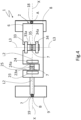
- first and second magnets 3, 4 and 23, 24 and 33, 34 are displaced, each pair being positioned in a repulsive magnetic configuration, along three longitudinal mutually orthogonal axes (see Fig. 6 ).
- the transducer device 1 comprises a first pair of first and second magnets 3, 4, a second pair of first and second magnets 23, 24, a third pair of first and second magnets 33, 34, having respectively a first transducer 5, a second transducer 25, a third transducer 35 arranged between said pairs of magnets.
- the first longitudinal axis L1 passes through the respective centres of mass of the first pair of the first and second magnets 3, 4 and is perpendicular both to the straight line X passing through the first and second reference point A, B and to the primary extension of the fissure F
- the second longitudinal axis L2 passes through the respective centres of mass of the second pair of first and second magnets 23, 24 and is parallel to the straight line X passing through the first and second reference point A B and perpendicular to the primary extension of the fissure F
- the third longitudinal axis L3 passes through the respective centres of mass of the third pair of first and second magnets 33, 34 and is perpendicular to the straight line X passing through the first and second reference A, B and parallel to the primary extension of the fissure F, if present.
- the third pair of first and second magnets 33, 34 in which the first and second magnet 33, 34 are cylindrical or prism-shaped, have respective first and second bases 33a, 34a which face one another, the first base 33a and the second base 34a are oriented perpendicular to the larger surface of the first element 6 and perpendicular to said second longitudinal axis L2, when identifiable, a third longitudinal axis L3 passes through the respective centres of mass of the first and second magnet 33, 34, the first and second magnet 33, 34 are connected respectively to or near to said second free end 6b, opposite the first end 6a, of the first element 6 and the transducer 35, and connected near to a second free end 7b of the second element 7 and arranged between the first and the second magnet 33, 34, in such a way that the third longitudinal axis L3 is perpendicular to the straight line X passing through the first and second reference points A, B and parallel to the maximum extension of the fissure F, if present
- a triaxial transducer device which is capable of detecting separately the individual displacement components for each of the three orthogonal axes thus defined.
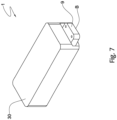
- the transducer device 1 comprises a cover 30, housed preferably on said first and second element 6, 7 or on said first and second spacer 8, 9.
- this cover 30 has a hollow box shape and is shaped so as substantially to cover the remaining components of the transducer device itself (including, for example, the first and second magnet 3, 4, the transducer 5 and any electrical connections) so as to protect them from any humidity, liquids or dirt present in the environment.
- this cover 30 has on one face an opening shaped so as to make considerable displacement possible relative to a device portion connected to one of the reference points of the structure.
- the method of the present invention comprises the operating steps set out above.
- the method for detecting the displacements between two reference points of the structure comprises:
- the data collected as a function of time will represent a graph having time as the abscissa, for example subdivided into weeks or months, and the amount in nanometres or micrometres of the relative displacement occurring between the first reference point A and the second reference point B as the ordinate.
- the method comprises:
- This evaluation system of the displacements as a function of time will also be able to make it possible to provide at least a first estimate of the timings for intervening, thus avoiding failure to implement effective interventions as a result of a lack of understanding of the need for good timing.
Landscapes
- Physics & Mathematics (AREA)
- General Physics & Mathematics (AREA)
- Measurement Of Length, Angles, Or The Like Using Electric Or Magnetic Means (AREA)
- Transmission And Conversion Of Sensor Element Output (AREA)
Claims (9)
- Wegaufnehmervorrichtung (1), die mit Referenzpunkten einer Struktur verbindbar ist, umfassend:• ein erstes Element (6), das zum einstückigen Befestigen an einem entsprechenden ersten Referenzpunkt (A) der Struktur bestimmt ist,• ein erstes Paar Magnete (33, 34), das einen ersten Magneten (33) und einen zweiten Magneten (34) umfasst, die entlang einer jeweiligen Längsachse (L1) so ausgerichtet angeordnet sind, dass diese sich gegenseitig magnetisch abstoßen,• einen Aufnehmer (35), der in der Nähe des ersten und zweiten Magneten (33, 34) angeordnet und dazu ausgelegt ist, eine Änderung des zwischen dem ersten und zweiten Magneten (33, 34) vorhandenen Magnetfelds zu erfassen und diese Änderung in ein Signal umzuwandeln, das von einer Verarbeitungseinheit verarbeitet werden kann,• ein zweites Element (7), das zum einstückigen Befestigen an einem entsprechenden zweiten Referenzpunkt (B) der Struktur bestimmt ist,• wobei die ersten und zweiten Elemente (6, 7) erste freie Enden (6a, 7a) und zweite freie Enden (6b, 7b) definieren, die den ersten freien Enden (6a, 7a) gegenüberliegen,• der erste Referenzpunkt (A) und der zweite Referenzpunkt (B) voneinander abweichende Punkte der Struktur sind,• und wobei entweder der erste Magnet (33), der zweite Magnet (34) oder der Aufnehmer (35) auf das ersten Element (6) beschränkt ist und die übrigen Elemente des ersten Magneten (33), des zweiten Magneten (34) oder des Aufnehmers (35) auf das zweiten Element (7) beschränkt sind, sodass eine relative und unabhängige Bewegung des ersten Referenzpunkts (A) oder des zweiten Referenzpunkts (B) eine Veränderung des Magnetfelds verursacht, die vom Aufnehmer (35) erfasst werden kann,dadurch gekennzeichnet, dass die Wegaufnehmervorrichtung (1) umfasst:• ein zweites Paar Magnete (23, 24), das einen weiteren ersten Magneten (23) und einen weiteren zweiten Magneten (24) umfasst, wobei der weitere erste Magnet (23) und der weitere zweite Magnet (24) zylindrisch oder prismenförmig sind und jeweils flache Basen (23a, 24a) aufweisen, die einander zugewandt sind,• einen weiteren Aufnehmer (25), der in der Nähe des weiteren ersten Magneten (24) und des weiteren zweiten Magneten (24) angeordnet ist und zum Erfassen einer Veränderung des zwischen dem weiteren ersten und zweiten Magneten (23, 24) vorhandenen Magnetfelds und zum Umwandeln der Veränderung in ein Signal ausgelegt ist, das von einer Verarbeitungseinheit verarbeitet werden kann,und dadurch, dass• die erste Basis (23a) senkrecht zu einer Hauptfläche des ersten Elements (6) ausgerichtet ist,• die zweite Basis (24a) senkrecht zur Hauptfläche des ersten Elements (6) und zu einer entsprechenden Hauptfläche des zweiten Elements (7) ausgerichtet ist,• der weitere erste Magnet (23) und der weitere zweite Magnet (24) eine zweite Längsachse (L2) definieren, die durch die jeweiligen Massenschwerpunkte der weiteren ersten und zweiten Magnete (23, 24) verläuft,• der weitere erste Magnet (23) und der weitere zweite Magnet (24) jeweils an oder in der Nähe von zweiten freien Enden (6b, 7b) verbunden sind, sodass die Bewegungen des weiteren ersten und zweiten Magneten (23, 24) oder des weiteren Aufnehmers (25), die durch Relativbewegungen des ersten oder zweiten Referenzpunkts (A, B) verursacht werden, parallel zur zweiten Längsachse (L2) verlaufen, wobei die zweite Längsachse (L2) parallel zu einer geraden Linie (X), die durch die ersten und zweiten Referenzpunkte (A, B) verläuft und senkrecht zur jeweiligen Längsachse (L1) angeordnet ist, entlang derer der erste Magnet (33) und der zweite Magnet (34) ausgerichtet sind.
- Aufnehmervorrichtung nach Anspruch 1, wobei der Aufnehmer (35) zwischen dem ersten Magneten (33) und dem zweiten Magneten (34) angeordnet ist.
- Aufnehmervorrichtung (1) nach Anspruch 1 oder 2, wobei der weitere Aufnehmer (25) zwischen dem weiteren ersten Magneten (23) und dem weiteren zweiten Magneten (24) angeordnet ist.
- Aufnehmervorrichtung (1) nach einem der vorhergehenden Ansprüche, wobei der erste und zweite Magnet (33, 34) und/oder der weitere erste und zweite Magnet (23, 24) Permanentmagnete sind.
- Aufnehmervorrichtung (1) nach einem der vorhergehenden Ansprüche, wobei der Aufnehmer (35) und/oder der weitere Aufnehmer (25) ein monoaxialer, biaxialer oder triaxialer Hall-Effekt-Sensor ist.
- Aufnehmervorrichtung (1) nach einem der vorhergehenden Ansprüche, umfassend einen Feuchtigkeitssensor und/oder einen Temperatursensor.
- Aufnehmervorrichtung (1) nach einem der vorhergehenden Ansprüche, umfassend• einen ersten Abstandhalter (8), der einstückig! zwischen dem ersten Referenzpunkt (A) und dem ersten Element (6) angeordnet ist,• einen zweiten Abstandhalter (9), der einstückig zwischen dem zweiten Referenzpunkt (B) und dem zweiten Element (7) angeordnet ist,• wobei das erste und das zweite Element (6, 7) plattenförmig sind und jeweils mittels des ersten Endes (6a, 7a) mit dem ersten bzw. zweiten Abstandhalter (8, 9) verbunden sind.
- Verfahren zum Erfassen von Bewegungen zwischen zwei Referenzpunkten einer Struktur, umfassend:• Bereitstellen einer Wegaufnehmervorrichtung (1), die nach einem oder mehreren der vorhergehenden Ansprüche ausgebildet ist,• Identifizieren eines Spalts in der Struktur,• Identifizieren eines ersten Referenzpunktes (A) und eines zweiten Referenzpunktes (B) der betreffenden Struktur,• Positionieren der Vorrichtung rittlings auf dem Spalt, wobei ein erstes Element (6) der Wegaufnehmervorrichtung (1) auf den ersten Referenzpunkt (A) auf einer durch eine Seite des Risses begrenzten Oberfläche beschränkt wird und ein zweites Element (7) der Wegaufnehmervorrichtung (1) auf den zweiten Referenzpunkt (B) auf einer durch die gegenüberliegende Seite des Spalts begrenzten Fläche beschränkt wird,• Verbinden einer Verarbeitungseinheit mit dem Aufnehmer (35) und dem weiteren Aufnehmer (25) der Wegaufnehmervorrichtung (1),• Erfassen einer Veränderung des Magnetfeldes, das zwischen den ersten und zweiten Magneten (33, 34) und zwischen den weiteren ersten und zweiten Magneten (23, 24) vorhanden ist, und Umwandeln der Veränderung in ein Signal, das von der Verarbeitungseinheit verarbeitet werden kann, und Überwachen der von den Aufnehmern (25, 35) gesammelten und von der Verarbeitungseinheit verarbeiteten Daten, um jegliche Relativbewegungen des ersten und zweiten Referenzpunkts (A, B) als Funktion der Zeit zu erfassen.
- Verfahren nach Anspruch 8, umfassend:• Senden einer Warnmeldung mittels einer Kommunikationseinrichtung, die mit der Verarbeitungseinheit wirkverbunden ist, wenn der Wert der Relativbewegungen des ersten und zweiten Referenzpunkts (A, B) einen vordefinierten Schwellenwert erreicht oder überschreitet.
Applications Claiming Priority (2)
| Application Number | Priority Date | Filing Date | Title |
|---|---|---|---|
| IT201700139633 | 2017-12-04 | ||
| PCT/IB2018/059623 WO2019142033A1 (en) | 2017-12-04 | 2018-12-04 | Displacement transducer device |
Publications (2)
| Publication Number | Publication Date |
|---|---|
| EP3721174A1 EP3721174A1 (de) | 2020-10-14 |
| EP3721174B1 true EP3721174B1 (de) | 2024-07-17 |
Family
ID=61731739
Family Applications (1)
| Application Number | Title | Priority Date | Filing Date |
|---|---|---|---|
| EP18829492.0A Active EP3721174B1 (de) | 2017-12-04 | 2018-12-04 | Wegaufnehmervorrichtung |
Country Status (14)
| Country | Link |
|---|---|
| US (1) | US11293783B2 (de) |
| EP (1) | EP3721174B1 (de) |
| JP (1) | JP2021505869A (de) |
| CN (1) | CN111448443A (de) |
| AU (1) | AU2018402674A1 (de) |
| BR (1) | BR112020011272A2 (de) |
| CA (1) | CA3083188A1 (de) |
| CL (1) | CL2020001450A1 (de) |
| CO (1) | CO2020006189A2 (de) |
| IL (1) | IL275134A (de) |
| MX (1) | MX2020004264A (de) |
| PE (1) | PE20201078A1 (de) |
| WO (1) | WO2019142033A1 (de) |
| ZA (1) | ZA202002885B (de) |
Families Citing this family (1)
| Publication number | Priority date | Publication date | Assignee | Title |
|---|---|---|---|---|
| JP7560024B2 (ja) * | 2021-09-02 | 2024-10-02 | 株式会社東設土木コンサルタント | 亀裂監視センサ |
Citations (1)
| Publication number | Priority date | Publication date | Assignee | Title |
|---|---|---|---|---|
| WO2014060986A1 (en) * | 2012-10-17 | 2014-04-24 | Henesis S.R.L. | Measurement system of the relative position between two separate structureal parts. |
Family Cites Families (13)
| Publication number | Priority date | Publication date | Assignee | Title |
|---|---|---|---|---|
| DE3809887A1 (de) | 1988-03-24 | 1989-10-05 | Teves Gmbh Alfred | Sensor zur messung mechanischer bewegungsgroessen |
| US6798195B2 (en) | 2001-12-14 | 2004-09-28 | Wabash Technologies, Inc. | Magnetic position sensor having shaped pole pieces at least partially formed of a non-magnetic material for producing a magnetic field having varying magnetic flux density along an axis |
| US7088095B1 (en) * | 2004-02-04 | 2006-08-08 | Honeywell International Inc. | Balanced magnetic linear displacement sensor |
| JP4853496B2 (ja) * | 2007-07-30 | 2012-01-11 | 株式会社デンソー | 位置検出センサ |
| DE102009035091A1 (de) * | 2009-07-28 | 2011-02-10 | Mahle International Gmbh | Positionssensor und Linearaktuator |
| FR2955655B1 (fr) * | 2010-01-27 | 2012-04-20 | Univ Franche Comte | Dispositif pour la mesure de positionnement d'un micro-actionneur |
| JP5056890B2 (ja) * | 2010-04-08 | 2012-10-24 | 株式会社デンソー | ストローク量検出装置 |
| JP5408508B2 (ja) * | 2011-11-01 | 2014-02-05 | 株式会社デンソー | 位置検出装置 |
| CN103323795B (zh) * | 2013-06-21 | 2015-04-08 | 中国人民解放军国防科学技术大学 | 一体式三轴磁传感器 |
| CN104296648A (zh) * | 2014-09-12 | 2015-01-21 | 浙江万安科技股份有限公司 | 制动阀用位移传感器及其ebs制动阀 |
| KR20160104950A (ko) * | 2015-02-27 | 2016-09-06 | 삼성전자주식회사 | 입력 장치, 이를 구비한 전자 장치 및 그 제어 방법 |
| CA3018905C (en) * | 2016-03-24 | 2023-09-26 | Lutron Electronics Co., Inc. | Remote load control device capable of orientation detection |
| ITUA20162508A1 (it) * | 2016-04-12 | 2017-10-12 | Safecertifiedstructure Ingegneria S R L | Metodo e dispositivo d’indagine per la misurazione di tensioni in una struttura di agglomerato |
-
2018
- 2018-12-04 US US16/769,048 patent/US11293783B2/en active Active
- 2018-12-04 BR BR112020011272-0A patent/BR112020011272A2/pt not_active Application Discontinuation
- 2018-12-04 CA CA3083188A patent/CA3083188A1/en not_active Abandoned
- 2018-12-04 PE PE2020000609A patent/PE20201078A1/es unknown
- 2018-12-04 CN CN201880077248.4A patent/CN111448443A/zh active Pending
- 2018-12-04 WO PCT/IB2018/059623 patent/WO2019142033A1/en not_active Ceased
- 2018-12-04 AU AU2018402674A patent/AU2018402674A1/en not_active Abandoned
- 2018-12-04 JP JP2020530497A patent/JP2021505869A/ja active Pending
- 2018-12-04 EP EP18829492.0A patent/EP3721174B1/de active Active
- 2018-12-04 MX MX2020004264A patent/MX2020004264A/es unknown
-
2020
- 2020-05-18 ZA ZA2020/02885A patent/ZA202002885B/en unknown
- 2020-05-20 CO CONC2020/0006189A patent/CO2020006189A2/es unknown
- 2020-05-29 CL CL2020001450A patent/CL2020001450A1/es unknown
- 2020-06-04 IL IL275134A patent/IL275134A/en unknown
Patent Citations (1)
| Publication number | Priority date | Publication date | Assignee | Title |
|---|---|---|---|---|
| WO2014060986A1 (en) * | 2012-10-17 | 2014-04-24 | Henesis S.R.L. | Measurement system of the relative position between two separate structureal parts. |
Also Published As
| Publication number | Publication date |
|---|---|
| US20200340831A1 (en) | 2020-10-29 |
| IL275134A (en) | 2020-07-30 |
| PE20201078A1 (es) | 2020-10-22 |
| CL2020001450A1 (es) | 2021-03-05 |
| JP2021505869A (ja) | 2021-02-18 |
| WO2019142033A1 (en) | 2019-07-25 |
| EP3721174A1 (de) | 2020-10-14 |
| US11293783B2 (en) | 2022-04-05 |
| BR112020011272A2 (pt) | 2020-11-24 |
| CN111448443A (zh) | 2020-07-24 |
| MX2020004264A (es) | 2020-08-03 |
| CA3083188A1 (en) | 2019-07-25 |
| AU2018402674A1 (en) | 2020-05-14 |
| ZA202002885B (en) | 2021-05-26 |
| CO2020006189A2 (es) | 2020-08-10 |
Similar Documents
| Publication | Publication Date | Title |
|---|---|---|
| JP5620475B2 (ja) | 磁気によって位置を求めるための方法及び装置 | |
| Li et al. | Development and application of a relative displacement sensor for structural health monitoring of composite bridges | |
| CN108519175B (zh) | 基于布拉格光纤光栅的可变量程的土体压力测量方法 | |
| JP6377817B2 (ja) | 非接触型磁気線形位置センサー | |
| CN109556774B (zh) | 铁磁钢中残余应力的无损监测系统及监测方法 | |
| JP7196921B2 (ja) | 非破壊検査装置、非破壊検査システム及び非破壊検査方法 | |
| Oats et al. | Digital image correlation advances in structural evaluation applications: A review | |
| EP3721174B1 (de) | Wegaufnehmervorrichtung | |
| KR101397273B1 (ko) | 자기력 센서 | |
| Nour et al. | A Novel Tilt and Acceleration Measurement System Based on Hall‐Effect Sensors Using Neural Networks | |
| Chen et al. | Vision-based displacement test method for high-rise building shaking table test | |
| JP2014232050A (ja) | 曲げ変形量計測方法および曲げ変形量計測装置 | |
| US9052218B2 (en) | Device for measuring the positioning of a microactuator | |
| Man et al. | Design and performance tests of a LED‐based two‐dimensional wireless crack propagation sensor | |
| Lee et al. | Vision-based 6-DOF displacement measurement of structures with a planar marker | |
| CN108801525A (zh) | 平面一点应力状态检测仪及检测方法 | |
| Li et al. | Turbine rotor dynamic balance vibration measurement based on the non-contact optical fiber grating sensing | |
| KR20100069883A (ko) | 레이저 변위센서를 이용한 연약지반 표층거동 분석 시스템 | |
| Moron et al. | Automatic system for detection and positioning of impacts in metals based on Arduino | |
| Tan et al. | Study on non-contact Fiber Bragg grating vibration sensor | |
| Nwabueze et al. | Displacement measurement using various Hall effect sensor-magnet configurations | |
| Groden et al. | The strain amplification sensor: A 3D‐printable stand‐alone strain gauge for low‐cost monitoring | |
| Zhang et al. | Magnetic-flux-based plumb line coordinometer for horizontal displacement monitoring of dam | |
| EA200802375A1 (ru) | Способ измерения линейного перемещения объекта и устройство для его осуществления | |
| Lee et al. | Multivision System for High‐Resolution Strain Measurement of Continuously Welded Rail |
Legal Events
| Date | Code | Title | Description |
|---|---|---|---|
| STAA | Information on the status of an ep patent application or granted ep patent |
Free format text: STATUS: UNKNOWN |
|
| STAA | Information on the status of an ep patent application or granted ep patent |
Free format text: STATUS: THE INTERNATIONAL PUBLICATION HAS BEEN MADE |
|
| PUAI | Public reference made under article 153(3) epc to a published international application that has entered the european phase |
Free format text: ORIGINAL CODE: 0009012 |
|
| STAA | Information on the status of an ep patent application or granted ep patent |
Free format text: STATUS: REQUEST FOR EXAMINATION WAS MADE |
|
| 17P | Request for examination filed |
Effective date: 20200505 |
|
| AK | Designated contracting states |
Kind code of ref document: A1 Designated state(s): AL AT BE BG CH CY CZ DE DK EE ES FI FR GB GR HR HU IE IS IT LI LT LU LV MC MK MT NL NO PL PT RO RS SE SI SK SM TR |
|
| AX | Request for extension of the european patent |
Extension state: BA ME |
|
| DAV | Request for validation of the european patent (deleted) | ||
| DAX | Request for extension of the european patent (deleted) | ||
| STAA | Information on the status of an ep patent application or granted ep patent |
Free format text: STATUS: EXAMINATION IS IN PROGRESS |
|
| 17Q | First examination report despatched |
Effective date: 20210917 |
|
| RAP3 | Party data changed (applicant data changed or rights of an application transferred) |
Owner name: SAFECERTIFIEDSTRUCTURE TECNOLOGIA S.R.L. |
|
| GRAP | Despatch of communication of intention to grant a patent |
Free format text: ORIGINAL CODE: EPIDOSNIGR1 |
|
| STAA | Information on the status of an ep patent application or granted ep patent |
Free format text: STATUS: GRANT OF PATENT IS INTENDED |
|
| INTG | Intention to grant announced |
Effective date: 20240305 |
|
| GRAS | Grant fee paid |
Free format text: ORIGINAL CODE: EPIDOSNIGR3 |
|
| GRAA | (expected) grant |
Free format text: ORIGINAL CODE: 0009210 |
|
| STAA | Information on the status of an ep patent application or granted ep patent |
Free format text: STATUS: THE PATENT HAS BEEN GRANTED |
|
| AK | Designated contracting states |
Kind code of ref document: B1 Designated state(s): AL AT BE BG CH CY CZ DE DK EE ES FI FR GB GR HR HU IE IS IT LI LT LU LV MC MK MT NL NO PL PT RO RS SE SI SK SM TR |
|
| REG | Reference to a national code |
Ref country code: CH Ref legal event code: EP |
|
| REG | Reference to a national code |
Ref country code: DE Ref legal event code: R096 Ref document number: 602018071956 Country of ref document: DE |
|
| REG | Reference to a national code |
Ref country code: IE Ref legal event code: FG4D |
|
| REG | Reference to a national code |
Ref country code: LT Ref legal event code: MG9D |
|
| REG | Reference to a national code |
Ref country code: NL Ref legal event code: MP Effective date: 20240717 |
|
| PG25 | Lapsed in a contracting state [announced via postgrant information from national office to epo] |
Ref country code: PT Free format text: LAPSE BECAUSE OF FAILURE TO SUBMIT A TRANSLATION OF THE DESCRIPTION OR TO PAY THE FEE WITHIN THE PRESCRIBED TIME-LIMIT Effective date: 20241118 |
|
| REG | Reference to a national code |
Ref country code: AT Ref legal event code: MK05 Ref document number: 1704531 Country of ref document: AT Kind code of ref document: T Effective date: 20240717 |
|
| PG25 | Lapsed in a contracting state [announced via postgrant information from national office to epo] |
Ref country code: NL Free format text: LAPSE BECAUSE OF FAILURE TO SUBMIT A TRANSLATION OF THE DESCRIPTION OR TO PAY THE FEE WITHIN THE PRESCRIBED TIME-LIMIT Effective date: 20240717 |
|
| PG25 | Lapsed in a contracting state [announced via postgrant information from national office to epo] |
Ref country code: PT Free format text: LAPSE BECAUSE OF FAILURE TO SUBMIT A TRANSLATION OF THE DESCRIPTION OR TO PAY THE FEE WITHIN THE PRESCRIBED TIME-LIMIT Effective date: 20241118 Ref country code: NL Free format text: LAPSE BECAUSE OF FAILURE TO SUBMIT A TRANSLATION OF THE DESCRIPTION OR TO PAY THE FEE WITHIN THE PRESCRIBED TIME-LIMIT Effective date: 20240717 |
|
| PG25 | Lapsed in a contracting state [announced via postgrant information from national office to epo] |
Ref country code: NO Free format text: LAPSE BECAUSE OF FAILURE TO SUBMIT A TRANSLATION OF THE DESCRIPTION OR TO PAY THE FEE WITHIN THE PRESCRIBED TIME-LIMIT Effective date: 20241017 |
|
| PG25 | Lapsed in a contracting state [announced via postgrant information from national office to epo] |
Ref country code: GR Free format text: LAPSE BECAUSE OF FAILURE TO SUBMIT A TRANSLATION OF THE DESCRIPTION OR TO PAY THE FEE WITHIN THE PRESCRIBED TIME-LIMIT Effective date: 20241018 Ref country code: FI Free format text: LAPSE BECAUSE OF FAILURE TO SUBMIT A TRANSLATION OF THE DESCRIPTION OR TO PAY THE FEE WITHIN THE PRESCRIBED TIME-LIMIT Effective date: 20240717 Ref country code: PL Free format text: LAPSE BECAUSE OF FAILURE TO SUBMIT A TRANSLATION OF THE DESCRIPTION OR TO PAY THE FEE WITHIN THE PRESCRIBED TIME-LIMIT Effective date: 20240717 |
|
| PG25 | Lapsed in a contracting state [announced via postgrant information from national office to epo] |
Ref country code: BG Free format text: LAPSE BECAUSE OF FAILURE TO SUBMIT A TRANSLATION OF THE DESCRIPTION OR TO PAY THE FEE WITHIN THE PRESCRIBED TIME-LIMIT Effective date: 20240717 |
|
| PG25 | Lapsed in a contracting state [announced via postgrant information from national office to epo] |
Ref country code: LV Free format text: LAPSE BECAUSE OF FAILURE TO SUBMIT A TRANSLATION OF THE DESCRIPTION OR TO PAY THE FEE WITHIN THE PRESCRIBED TIME-LIMIT Effective date: 20240717 |
|
| PG25 | Lapsed in a contracting state [announced via postgrant information from national office to epo] |
Ref country code: IS Free format text: LAPSE BECAUSE OF FAILURE TO SUBMIT A TRANSLATION OF THE DESCRIPTION OR TO PAY THE FEE WITHIN THE PRESCRIBED TIME-LIMIT Effective date: 20241117 Ref country code: AT Free format text: LAPSE BECAUSE OF FAILURE TO SUBMIT A TRANSLATION OF THE DESCRIPTION OR TO PAY THE FEE WITHIN THE PRESCRIBED TIME-LIMIT Effective date: 20240717 |
|
| PG25 | Lapsed in a contracting state [announced via postgrant information from national office to epo] |
Ref country code: HR Free format text: LAPSE BECAUSE OF FAILURE TO SUBMIT A TRANSLATION OF THE DESCRIPTION OR TO PAY THE FEE WITHIN THE PRESCRIBED TIME-LIMIT Effective date: 20240717 |
|
| PG25 | Lapsed in a contracting state [announced via postgrant information from national office to epo] |
Ref country code: ES Free format text: LAPSE BECAUSE OF FAILURE TO SUBMIT A TRANSLATION OF THE DESCRIPTION OR TO PAY THE FEE WITHIN THE PRESCRIBED TIME-LIMIT Effective date: 20240717 Ref country code: RS Free format text: LAPSE BECAUSE OF FAILURE TO SUBMIT A TRANSLATION OF THE DESCRIPTION OR TO PAY THE FEE WITHIN THE PRESCRIBED TIME-LIMIT Effective date: 20241017 |
|
| PG25 | Lapsed in a contracting state [announced via postgrant information from national office to epo] |
Ref country code: RS Free format text: LAPSE BECAUSE OF FAILURE TO SUBMIT A TRANSLATION OF THE DESCRIPTION OR TO PAY THE FEE WITHIN THE PRESCRIBED TIME-LIMIT Effective date: 20241017 Ref country code: PL Free format text: LAPSE BECAUSE OF FAILURE TO SUBMIT A TRANSLATION OF THE DESCRIPTION OR TO PAY THE FEE WITHIN THE PRESCRIBED TIME-LIMIT Effective date: 20240717 Ref country code: NO Free format text: LAPSE BECAUSE OF FAILURE TO SUBMIT A TRANSLATION OF THE DESCRIPTION OR TO PAY THE FEE WITHIN THE PRESCRIBED TIME-LIMIT Effective date: 20241017 Ref country code: LV Free format text: LAPSE BECAUSE OF FAILURE TO SUBMIT A TRANSLATION OF THE DESCRIPTION OR TO PAY THE FEE WITHIN THE PRESCRIBED TIME-LIMIT Effective date: 20240717 Ref country code: IS Free format text: LAPSE BECAUSE OF FAILURE TO SUBMIT A TRANSLATION OF THE DESCRIPTION OR TO PAY THE FEE WITHIN THE PRESCRIBED TIME-LIMIT Effective date: 20241117 Ref country code: HR Free format text: LAPSE BECAUSE OF FAILURE TO SUBMIT A TRANSLATION OF THE DESCRIPTION OR TO PAY THE FEE WITHIN THE PRESCRIBED TIME-LIMIT Effective date: 20240717 Ref country code: GR Free format text: LAPSE BECAUSE OF FAILURE TO SUBMIT A TRANSLATION OF THE DESCRIPTION OR TO PAY THE FEE WITHIN THE PRESCRIBED TIME-LIMIT Effective date: 20241018 Ref country code: FI Free format text: LAPSE BECAUSE OF FAILURE TO SUBMIT A TRANSLATION OF THE DESCRIPTION OR TO PAY THE FEE WITHIN THE PRESCRIBED TIME-LIMIT Effective date: 20240717 Ref country code: ES Free format text: LAPSE BECAUSE OF FAILURE TO SUBMIT A TRANSLATION OF THE DESCRIPTION OR TO PAY THE FEE WITHIN THE PRESCRIBED TIME-LIMIT Effective date: 20240717 Ref country code: BG Free format text: LAPSE BECAUSE OF FAILURE TO SUBMIT A TRANSLATION OF THE DESCRIPTION OR TO PAY THE FEE WITHIN THE PRESCRIBED TIME-LIMIT Effective date: 20240717 Ref country code: AT Free format text: LAPSE BECAUSE OF FAILURE TO SUBMIT A TRANSLATION OF THE DESCRIPTION OR TO PAY THE FEE WITHIN THE PRESCRIBED TIME-LIMIT Effective date: 20240717 |
|
| PG25 | Lapsed in a contracting state [announced via postgrant information from national office to epo] |
Ref country code: DK Free format text: LAPSE BECAUSE OF FAILURE TO SUBMIT A TRANSLATION OF THE DESCRIPTION OR TO PAY THE FEE WITHIN THE PRESCRIBED TIME-LIMIT Effective date: 20240717 Ref country code: SM Free format text: LAPSE BECAUSE OF FAILURE TO SUBMIT A TRANSLATION OF THE DESCRIPTION OR TO PAY THE FEE WITHIN THE PRESCRIBED TIME-LIMIT Effective date: 20240717 Ref country code: RO Free format text: LAPSE BECAUSE OF FAILURE TO SUBMIT A TRANSLATION OF THE DESCRIPTION OR TO PAY THE FEE WITHIN THE PRESCRIBED TIME-LIMIT Effective date: 20240717 |
|
| REG | Reference to a national code |
Ref country code: DE Ref legal event code: R097 Ref document number: 602018071956 Country of ref document: DE |
|
| PG25 | Lapsed in a contracting state [announced via postgrant information from national office to epo] |
Ref country code: EE Free format text: LAPSE BECAUSE OF FAILURE TO SUBMIT A TRANSLATION OF THE DESCRIPTION OR TO PAY THE FEE WITHIN THE PRESCRIBED TIME-LIMIT Effective date: 20240717 |
|
| PGFP | Annual fee paid to national office [announced via postgrant information from national office to epo] |
Ref country code: CH Payment date: 20250101 Year of fee payment: 7 |
|
| PG25 | Lapsed in a contracting state [announced via postgrant information from national office to epo] |
Ref country code: CZ Free format text: LAPSE BECAUSE OF FAILURE TO SUBMIT A TRANSLATION OF THE DESCRIPTION OR TO PAY THE FEE WITHIN THE PRESCRIBED TIME-LIMIT Effective date: 20240717 |
|
| PG25 | Lapsed in a contracting state [announced via postgrant information from national office to epo] |
Ref country code: SK Free format text: LAPSE BECAUSE OF FAILURE TO SUBMIT A TRANSLATION OF THE DESCRIPTION OR TO PAY THE FEE WITHIN THE PRESCRIBED TIME-LIMIT Effective date: 20240717 |
|
| PLBE | No opposition filed within time limit |
Free format text: ORIGINAL CODE: 0009261 |
|
| STAA | Information on the status of an ep patent application or granted ep patent |
Free format text: STATUS: NO OPPOSITION FILED WITHIN TIME LIMIT |
|
| 26N | No opposition filed |
Effective date: 20250422 |
|
| PG25 | Lapsed in a contracting state [announced via postgrant information from national office to epo] |
Ref country code: MC Free format text: LAPSE BECAUSE OF FAILURE TO SUBMIT A TRANSLATION OF THE DESCRIPTION OR TO PAY THE FEE WITHIN THE PRESCRIBED TIME-LIMIT Effective date: 20240717 |
|
| PG25 | Lapsed in a contracting state [announced via postgrant information from national office to epo] |
Ref country code: LU Free format text: LAPSE BECAUSE OF NON-PAYMENT OF DUE FEES Effective date: 20241204 |
|
| PG25 | Lapsed in a contracting state [announced via postgrant information from national office to epo] |
Ref country code: SE Free format text: LAPSE BECAUSE OF FAILURE TO SUBMIT A TRANSLATION OF THE DESCRIPTION OR TO PAY THE FEE WITHIN THE PRESCRIBED TIME-LIMIT Effective date: 20240717 |
|
| REG | Reference to a national code |
Ref country code: BE Ref legal event code: MM Effective date: 20241231 |
|
| PG25 | Lapsed in a contracting state [announced via postgrant information from national office to epo] |
Ref country code: BE Free format text: LAPSE BECAUSE OF NON-PAYMENT OF DUE FEES Effective date: 20241231 |
|
| PG25 | Lapsed in a contracting state [announced via postgrant information from national office to epo] |
Ref country code: IE Free format text: LAPSE BECAUSE OF NON-PAYMENT OF DUE FEES Effective date: 20241204 |
|
| REG | Reference to a national code |
Ref country code: CH Ref legal event code: U11 Free format text: ST27 STATUS EVENT CODE: U-0-0-U10-U11 (AS PROVIDED BY THE NATIONAL OFFICE) Effective date: 20260101 |
|
| PGFP | Annual fee paid to national office [announced via postgrant information from national office to epo] |
Ref country code: DE Payment date: 20251211 Year of fee payment: 8 |
|
| PGFP | Annual fee paid to national office [announced via postgrant information from national office to epo] |
Ref country code: GB Payment date: 20251219 Year of fee payment: 8 |
|
| PGFP | Annual fee paid to national office [announced via postgrant information from national office to epo] |
Ref country code: FR Payment date: 20251229 Year of fee payment: 8 |
|
| PG25 | Lapsed in a contracting state [announced via postgrant information from national office to epo] |
Ref country code: IT Free format text: LAPSE BECAUSE OF FAILURE TO SUBMIT A TRANSLATION OF THE DESCRIPTION OR TO PAY THE FEE WITHIN THE PRESCRIBED TIME-LIMIT Effective date: 20240717 |
|
| PG25 | Lapsed in a contracting state [announced via postgrant information from national office to epo] |
Ref country code: CY Free format text: LAPSE BECAUSE OF FAILURE TO SUBMIT A TRANSLATION OF THE DESCRIPTION OR TO PAY THE FEE WITHIN THE PRESCRIBED TIME-LIMIT; INVALID AB INITIO Effective date: 20181204 |