EP3721177B1 - Vorrichtung zur messung der durchflussrate eines fluids, wie etwa beton, in einer mit einer bohrmaschine verbundenen pumpanlage - Google Patents
Vorrichtung zur messung der durchflussrate eines fluids, wie etwa beton, in einer mit einer bohrmaschine verbundenen pumpanlage Download PDFInfo
- Publication number
- EP3721177B1 EP3721177B1 EP18825792.7A EP18825792A EP3721177B1 EP 3721177 B1 EP3721177 B1 EP 3721177B1 EP 18825792 A EP18825792 A EP 18825792A EP 3721177 B1 EP3721177 B1 EP 3721177B1
- Authority
- EP
- European Patent Office
- Prior art keywords
- transmitting module
- flow rate
- pump
- concrete
- motor pump
- Prior art date
- Legal status (The legal status is an assumption and is not a legal conclusion. Google has not performed a legal analysis and makes no representation as to the accuracy of the status listed.)
- Active
Links
Images




Classifications
-
- G—PHYSICS
- G01—MEASURING; TESTING
- G01F—MEASURING VOLUME, VOLUME FLOW, MASS FLOW OR LIQUID LEVEL; METERING BY VOLUME
- G01F1/00—Measuring the volume flow or mass flow of fluid or fluent solid material wherein the fluid passes through a meter in a continuous flow
- G01F1/66—Measuring the volume flow or mass flow of fluid or fluent solid material wherein the fluid passes through a meter in a continuous flow by measuring frequency, phase shift or propagation time of electromagnetic or other waves, e.g. using ultrasonic flowmeters
- G01F1/666—Measuring the volume flow or mass flow of fluid or fluent solid material wherein the fluid passes through a meter in a continuous flow by measuring frequency, phase shift or propagation time of electromagnetic or other waves, e.g. using ultrasonic flowmeters by detecting noise and sounds generated by the flowing fluid
-
- E—FIXED CONSTRUCTIONS
- E02—HYDRAULIC ENGINEERING; FOUNDATIONS; SOIL SHIFTING
- E02D—FOUNDATIONS; EXCAVATIONS; EMBANKMENTS; UNDERGROUND OR UNDERWATER STRUCTURES
- E02D5/00—Bulkheads, piles, or other structural elements specially adapted to foundation engineering
- E02D5/22—Piles
- E02D5/34—Concrete or concrete-like piles cast in position ; Apparatus for making same
-
- E—FIXED CONSTRUCTIONS
- E02—HYDRAULIC ENGINEERING; FOUNDATIONS; SOIL SHIFTING
- E02D—FOUNDATIONS; EXCAVATIONS; EMBANKMENTS; UNDERGROUND OR UNDERWATER STRUCTURES
- E02D5/00—Bulkheads, piles, or other structural elements specially adapted to foundation engineering
- E02D5/22—Piles
- E02D5/56—Screw piles
-
- G—PHYSICS
- G01—MEASURING; TESTING
- G01F—MEASURING VOLUME, VOLUME FLOW, MASS FLOW OR LIQUID LEVEL; METERING BY VOLUME
- G01F25/00—Testing or calibration of apparatus for measuring volume, volume flow or liquid level or for metering by volume
- G01F25/10—Testing or calibration of apparatus for measuring volume, volume flow or liquid level or for metering by volume of flowmeters
-
- G—PHYSICS
- G01—MEASURING; TESTING
- G01F—MEASURING VOLUME, VOLUME FLOW, MASS FLOW OR LIQUID LEVEL; METERING BY VOLUME
- G01F3/00—Measuring the volume flow of fluids or fluent solid material wherein the fluid passes through the meter in successive and more or less isolated quantities, the meter being driven by the flow
-
- G—PHYSICS
- G01—MEASURING; TESTING
- G01F—MEASURING VOLUME, VOLUME FLOW, MASS FLOW OR LIQUID LEVEL; METERING BY VOLUME
- G01F3/00—Measuring the volume flow of fluids or fluent solid material wherein the fluid passes through the meter in successive and more or less isolated quantities, the meter being driven by the flow
- G01F3/02—Measuring the volume flow of fluids or fluent solid material wherein the fluid passes through the meter in successive and more or less isolated quantities, the meter being driven by the flow with measuring chambers which expand or contract during measurement
- G01F3/04—Measuring the volume flow of fluids or fluent solid material wherein the fluid passes through the meter in successive and more or less isolated quantities, the meter being driven by the flow with measuring chambers which expand or contract during measurement having rigid movable walls
- G01F3/14—Measuring the volume flow of fluids or fluent solid material wherein the fluid passes through the meter in successive and more or less isolated quantities, the meter being driven by the flow with measuring chambers which expand or contract during measurement having rigid movable walls comprising reciprocating pistons, e.g. reciprocating in a rotating body
-
- E—FIXED CONSTRUCTIONS
- E02—HYDRAULIC ENGINEERING; FOUNDATIONS; SOIL SHIFTING
- E02D—FOUNDATIONS; EXCAVATIONS; EMBANKMENTS; UNDERGROUND OR UNDERWATER STRUCTURES
- E02D2600/00—Miscellaneous
- E02D2600/10—Miscellaneous comprising sensor means
Definitions
- the hole While the hole is being drilled in the ground, the hole itself can be filled with a stabilizing fluid (for example, a bentonite mud or a polymer mixture), which prevents the hole from collapsing due to the hydrostatic pressure generated on the walls of the hole.
- a stabilizing fluid for example, a bentonite mud or a polymer mixture
- a hardening fluid usually concrete, is pumped into the drilling tool so that it flows out of the lower part of the tool and starts filling the hole starting from the bottom, while the tool is caused to progressively resurface.
- the hardening fluid is introduced into the tool by means of a pumping plant, which comprises a motor pump connected to the machine by means of a flexible pipe, which is preferably fixed to the upper end of the tool by means of a rotary joint, which allows the tool to freely rotate relative to the pipe.
- a pumping plant which comprises a motor pump connected to the machine by means of a flexible pipe, which is preferably fixed to the upper end of the tool by means of a rotary joint, which allows the tool to freely rotate relative to the pipe.
- the electrical signal controlling the switching of the solenoid valve is intercepted on board the distribution board of the motor pump. Indeed, every switching of the solenoid valve corresponds to an actuation of the pistons to carry out a pump stroke, hence the electrical switching signal can be directly associated with a pump stroke. In these cases, once the electrical signal controlling the pistons is intercepted, it is sent, through a wired or wireless technology, to the drilling apparatus, where the signal is processed, as already mentioned above.
- the flow rate item of information is then displayed to the operator on board the drilling apparatus, who changes the operating speed of the pump based on the detected data, compared with the desired flow rate value. Therefore, the transmission of the item of information concerning the pump strokes of the pump itself to the drilling machine is very important.
- this management is usually called automatic resurfacing.
- the control unit of the drilling machine receives, as an input, the item of information concerning the pump strokes per minute and, based on the latter, calculates the volume of fluid pumped into the hole. As a function of the volume introduced into the hole, the control unit automatically adjusts the resurfacing speed of the drilling tool.
- CN1192793A relates to the determination of the flow rate of concrete in a pumping plant connected to a drilling machine provided with a drilling tool.
- An electromagnetic flowmeter is used to determine the concrete supply amount.
- Drilling tool 21 is provided with an inner duct, which extends through it along its entirety and permits the passage of the fluid, which, during a foundation pile manufacturing step, is introduced from an upper end of drilling tool 21 and pumped so that it flows out of the lower end. Once the desired drilling depth has been reached, the fluid is pumped into drilling tool 21 so that it flows out of the lower part of drilling tool 21 and starts filling the hole starting from the bottom, while drilling tool 21 is caused to progressively resurface.
- the fluid is introduced into drilling tool 21 by means of a pumping plant.
- the fluid is a hardening fluid, in particular concrete.
- transmitting module 4 detects the vibrations of motor pump 1, generated during the operation, and processes them so as to count the "pump strokes". Subsequently, transmitting module 4 transmits the item of information, through wireless connection, to receiving module 5 mounted on drilling machine 3.
- Said receiving module 5 is connected to a control system, in particular to a programmable controller 32 (CPU) of drilling machine 3.
- Receiving module 5 delivers to the programmable controller, preferably in the form of a binary voltage signal, the items of information received from transmitting module 4.
- the receiving module 5 is configured to send the signal indicating the flow rate to a displaying device, which can conveniently be comprised in drilling machine 3, so as to display at least one among the following items of information: frequency of the pump strokes of motor pump 1, total number of pump strokes, flow rate of the fluid, total volume of pumped fluid.
- Transmitting module 4, 4a is preferably configured so that, if the intensity of the accelerations generated by the vibrations detected by accelerometer 9 remains within detection threshold values, said accelerations are not taken into account to emit the signal generated by transmitting module 4, 4a. In this way, the accelerations due to vibrations that are present when motor pump 1 is in an "empty" or “load-less” operating condition, namely when motor pump 1 has the motor turned on, but does not pump the fluid towards drilling machine 3, are not taken into account. Therefore, the measurement is more reliable.
- transmitting module 4, 4a comprises at least one control element, such as a trimmer 15 or a button 20, to set the values of the acceleration amplitudes corresponding to the detection thresholds.
- Transmitting module 4 preferably comprises a button 16 to carry out the self-adjustment of the measuring device.
- a button 17 to turn on and off transmitting module 4.
- transmitting module 4 can be automatically turned off after a predetermined amount of time in which it is not used.
- receiving module 5 has an outer casing, which can be made, for example, of a plastic or metallic material, conveniently resistant to atmospheric conditions, and comprises a base box 30 and a lid 31.
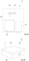
- Figure 5a shows a plant view of receiving module 5 without lid 31.
- base box 30 houses an electronic board 25, which is connected to at least one microcontroller 26 MCU and a radio receiver 27.
- Microcontroller 26 can be connected to the control system of drilling machine 3 by means of an electrical connector 28.
- Receiving module 5 can be provided with an electrical connector 29 to be connected, for example, to the electrical system of drilling machine 3, so as to receive the electrical power needed to supply power to receiving module 5.
- receiving module 5 can include a battery, conveniently a rechargeable battery, to supply power.
- Receiving module 5 can be fixed to drilling machine 3 in a permanent manner or, alternatively, it can be connected to a magnetic base (not shown) or to another removable, rigid connection system, which allows it to be easily removed.
- FIG. 6 shows a possible installation mode of receiving module 5, which is mounted on drilling machine 3.
- receiving module 5 is mounted on an outer part of drilling machine 3, but it can also be mounted on an inner part.
- receiving module 5 can be integrated in or mounted on an electronic control unit of drilling machine 3.
- Receiving module 5 is connected to programmable controller 32 (CPU), which is part of the control system of drilling machine 3.
- the connection shown between receiving module 5 and programmable controller 32 is a wired connection, but a wireless connection is also possible. Through this connection, receiving module 5 transmits the item of information concerning the calculation of the pump strokes to the control system of drilling machine 3.
- Figure 7 shows, by way of example, a schematic representation of a measurement of the accelerations generated by the vibrations of the pumping plant as a function of the time, acquired by transmitting module 4.
- a diagram is shown, with the time on the horizontal axis and the amplitude of the accelerations on the vertical axis.
- the accelerations were measured in one single direction (e.g. direction x) by means of a single-axis accelerometer; however, all the concepts explained hereinafter also apply to measurements of the vibrations oriented along remaining axes y and z and measured with three-axis accelerometers or with a multitude of properly oriented single-axis accelerometers.
- the values of "Gmax positive” and “Gmax negative” detected during the self-adjustment can be different from one another and, hence, the value of the "positive stroke detection threshold” resulting from “Gmax positive” + stroke-offset can be, in general, different from the value of the "negative stroke detection threshold” resulting from “Gmax negative” - stroke-offset.
- the threshold interval ranges between the two stroke detection thresholds, i.e. "stroke detection threshold (+)” and “stroke detection threshold (-)".
- the calibration is carried out only when the measuring device is started for the first time and is repeated when the device is installed on a new pumping plant.
- This filter which is a time filter and is indicated as “time filter” in figure 7 , is activated every time the acceleration value exceeds a "stroke detection threshold", namely every time the acceleration diagram goes out of the area defined between the two "stroke detection thresholds” and remains active for an adjustable time interval indicated as “time filter”.
- trimmer 14, or button 19 present on transmitting module 4, 4a, it is possible to set the duration of the "time filter” in the diagram, which will help distinguish pump strokes from said secondary acceleration peaks.
- control system of drilling machine 3 is configured to receive, from receiving module 5, signals indicating the fluid flow rate and, based on said signals, to carry out the following operations: showing the user the value of the instantaneous flow rate of the fluid, showing the user the volume of pumped fluid, and recording these items of information.
- These items of information are handy for the user.
- the recorded items of information are useful to create a time record of the performed operations, which, for instance, is useful to keep track of the progression of the works in the drilling site.
- the control unit is optionally adapted to record further items of information, depending on the needs.
- the output data of the transmitting module 4, 4a is sent to a displaying device, such as a display, which will show the measured data.
- the displaying device is placed on drilling machine 3 in a position visible by the operator, for example in the cabin.
- the displaying device is not connected to the control system of drilling machine 3 and, therefore, does not interact with drilling machine 3.
- the data displayed by the displaying device gives the operator indications on drilling machine 3 and the operator, based on this data, can adjust the operating parameters of drilling machine 3 accordingly by acting upon the controls of drilling machine 3, for example adjusting the resurfacing speed of drilling tool 21 by acting upon the controls available in the cabin.
Landscapes
- Engineering & Computer Science (AREA)
- Structural Engineering (AREA)
- Physics & Mathematics (AREA)
- Fluid Mechanics (AREA)
- General Physics & Mathematics (AREA)
- General Life Sciences & Earth Sciences (AREA)
- Life Sciences & Earth Sciences (AREA)
- Mining & Mineral Resources (AREA)
- Paleontology (AREA)
- Civil Engineering (AREA)
- General Engineering & Computer Science (AREA)
- Electromagnetism (AREA)
- Control Of Positive-Displacement Pumps (AREA)
Claims (15)
- Vorrichtung, die konfiguriert ist, um die Durchflussmenge von Beton zu messen, der in einer Pumpanlage fließen soll, die mit einer Bohrmaschine (3) verbunden ist, die mit einem Bohrwerkzeug (21) versehen ist, wobei die Pumpanlage eine Kolbenmotorpumpe (1) und eine Verbindungsleitung (2) aufweist, um den Beton von der Motorpumpe (1) zum Bohrwerkzeug (21) zu leiten; wobei die Vorrichtung aufweist:- mindestens ein Sendemodul (4, 4a), das starr und abnehmbar an der Pumpanlage angebracht werden kann und mindestens einen Beschleunigungsmesser (9) aufweist,- ein Empfangsmodul (5), das mit der Bohrmaschine (3) verbunden werden kann;wobei das Sendemodul (4, 4a) konfiguriert ist, die durch die Vibrationen der Pumpanlage während des Pumpens des Betons erzeugten Beschleunigungen zu erfassen, wobei die Beschleunigungen die Durchflussrate des Betons anzeigen, und ein Signal, das auf der Grundlage der erfassten Beschleunigungen verarbeitet wird, durch drahtlose Übertragung an das Empfangsmodul (5) zu senden,wobei das Empfangsmodul (5) konfiguriert ist, um das Signal von dem Sendemodul (4, 4a) zu empfangen und auf der Grundlage des empfangenen Signals ein Signal zu senden, das die Durchflussrate des gepumpten Betons anzeigt;wobei das Sendemodul (4, 4a) so konfiguriert ist, dass, wenn die Intensität der durch den Beschleunigungsmesser (9) erfassten Beschleunigungen innerhalb von Erfassungsschwellenwerten bleibt, die Beschleunigungen nicht berücksichtigt werden, um das durch das Sendemodul (4, 4a) erzeugte Signal zu senden;wobei das Sendemodul (4, 4a) konfiguriert ist, um die Intensität der Vibrationen für eine vorbestimmte Kalibrierungszeit zu analysieren, während der sich ein Motor der Motorpumpe (1) in einem Betriebszustand befindet, in dem die Motorpumpe (1) den Beton nicht pumpt, und um ein Kalibrierungsintervall zu bestimmen, das durch die maximalen positiven und negativen Werte der in der Kalibrierungszeit erfassten Beschleunigung definiert ist; wobei die Erfassungsschwellenwerte auf der Grundlage der Kalibrierungszeit bestimmt werden.
- Vorrichtung nach Anspruch 1, wobei das Sendemodul (4) Befestigungsmittel aufweist, um das Sendemodul (4) starr und abnehmbar an der Motorpumpe (1) der Pumpanlage zu befestigen.
- Vorrichtung nach Anspruch 1, wobei das Sendemodul (4a) Befestigungsmittel aufweist, um das Sendemodul (4a) starr und abnehmbar an der Verbindungsleitung (2) der Pumpanlage zu befestigen.
- Vorrichtung nach einem der vorhergehenden Ansprüche, wobei das Empfangsmodul (5) konfiguriert ist, um das die Durchflussrate anzeigende Signal an ein Steuersystem der Bohrmaschine (3) zu senden.
- Vorrichtung nach einem der vorhergehenden Ansprüche, wobei das Empfangsmodul (5) konfiguriert ist, um das die Durchflussrate anzeigende Signal an eine Anzeigevorrichtung zu senden, um mindestens eine der folgenden Daten anzuzeigen:
Häufigkeit der Pumpenhübe der Motorpumpe (1), Gesamtzahl der Pumpenhübe, Durchflussmenge des Betons, Gesamtvolumen des gepumpten Betons. - Vorrichtung nach einem der vorhergehenden Ansprüche, aufweisend mindestens ein Display (18) zur Anzeige von Betriebsinformationen.
- Vorrichtung nach einem der vorhergehenden Ansprüche, wobei das Sendemodul (4, 4a) mindestens ein Bedienelement, wie einen Trimmer (15) oder einen Taster (20), zur Einstellung der Erfassungsschwellenwerte für die erfassten Beschleunigungen aufweist.
- Vorrichtung nach einem der vorhergehenden Ansprüche, wobei das Sendemodul (4, 4a) so konfiguriert ist, dass es, wenn die erfasste Beschleunigung einen der Erfassungsschwellenwerte überschreitet, ein der Überschreitung des Schwellenwerts entsprechendes Signal erzeugt.
- Vorrichtung nach Anspruch 8, bei der das Sendemodul (4, 4a) so konfiguriert ist, dass, wenn die Amplitude der erfassten Beschleunigungen einen der Erfassungsschwellenwerte überschreitet, die auf die Überschreitung folgenden Beschleunigungen nicht berücksichtigt werden, um das vom Sendemodul (4, 4a) ausgegebene Signal zu senden, wenn diese Beschleunigungen in einem durch einen Zeitfilter definierten Zeitintervall stattfinden.
- Vorrichtung nach Anspruch 9, wobei das Sendemodul (4, 4a) mindestens ein Bedienelement, wie einen Trimmer (14) oder eine Taste (20), zur Einstellung des Zeitfilters aufweist.
- Anordnung mit einer Vorrichtung nach einem der vorhergehenden Ansprüche und einer Bohrmaschine (3), der das Empfangsmodul (5) zugeordnet ist.
- Anordnung nach Anspruch 11, wobei ein Steuersystem der Bohrmaschine (3) konfiguriert ist, um von dem Empfangsmodul (5) Signale zu empfangen, die die Durchflussrate des gepumpten Betons anzeigen, und auf der Grundlage dieser Signale die folgenden Vorgänge auszuführen: Anzeigen des Wertes der momentanen Durchflussrate des gepumpten Betons für den Benutzer, Anzeigen des Volumens des gepumpten Betons für den Benutzer und Aufzeichnen dieser Daten.
- Anordnung nach Anspruch 11 oder 12, wobei ein Steuerungssystem der Bohrmaschine (3) konfiguriert ist, um eine automatische Nachbearbeitungsgeschwindigkeit des Bohrwerkzeugs (21) einzustellen, die auf den von dem Empfangsmodul (5) erzeugten Werten basiert und die Durchflussmenge des von der Motorpumpe (1) gepumpten Betons angibt.
- Anordnung nach Anspruch 11, 12 oder 13, die eine Pumpanlage aufweist, die mit der mit einem Bohrwerkzeug (21) versehenen Bohrmaschine (3) verbunden ist, wobei die Pumpanlage eine Kolbenmotorpumpe (1) und eine Verbindungsleitung (2) aufweist, um Beton von der Motorpumpe (1) zu dem Bohrwerkzeug (21) zu leiten.
- Verwendung einer Vorrichtung nach einem der Ansprüche 1 bis 10 zum Messen der Durchflussmenge von Beton, der in einer Pumpanlage fließen soll, die mit einer Bohrmaschine (3) verbunden ist, die mit einem Bohrwerkzeug (21) versehen ist, wobei die Pumpanlage eine Kolbenmotorpumpe (1) und eine Verbindungsleitung (2) aufweist, um den von der Motorpumpe (1) gepumpten Beton zum Bohrwerkzeug (21) zu führen.
Applications Claiming Priority (2)
| Application Number | Priority Date | Filing Date | Title |
|---|---|---|---|
| IT201700141585 | 2017-12-07 | ||
| PCT/IB2018/059696 WO2019111190A1 (en) | 2017-12-07 | 2018-12-06 | Device to measure the flow rate of a fluid, such as concrete, in a pumping plant connected to a drilling machine |
Publications (3)
| Publication Number | Publication Date |
|---|---|
| EP3721177A1 EP3721177A1 (de) | 2020-10-14 |
| EP3721177B1 true EP3721177B1 (de) | 2025-04-09 |
| EP3721177C0 EP3721177C0 (de) | 2025-04-09 |
Family
ID=61581650
Family Applications (1)
| Application Number | Title | Priority Date | Filing Date |
|---|---|---|---|
| EP18825792.7A Active EP3721177B1 (de) | 2017-12-07 | 2018-12-06 | Vorrichtung zur messung der durchflussrate eines fluids, wie etwa beton, in einer mit einer bohrmaschine verbundenen pumpanlage |
Country Status (5)
| Country | Link |
|---|---|
| US (1) | US11747182B2 (de) |
| EP (1) | EP3721177B1 (de) |
| AU (1) | AU2018378420A1 (de) |
| CA (1) | CA3082244A1 (de) |
| WO (1) | WO2019111190A1 (de) |
Families Citing this family (4)
| Publication number | Priority date | Publication date | Assignee | Title |
|---|---|---|---|---|
| US20210172432A1 (en) * | 2019-12-09 | 2021-06-10 | Ami Global | Method for surveillance of air operated diaphragm pump and surveillance device |
| JP7296071B1 (ja) | 2022-02-07 | 2023-06-22 | 有限会社ベトンテック | 流量計および流量計測システム |
| IT202200021888A1 (it) | 2022-10-24 | 2024-04-24 | Soilmec Spa | Procedimento, sistema e programma per elaboratore per sorvegliare un dispositivo da sorvegliare quale per esempio una fresa per diaframmi, perforatrice per pali e altre fondazioni e altre macchine operatrici. |
| CN115616974B (zh) * | 2022-11-11 | 2025-08-19 | 中交第三航务工程局有限公司 | 一种管桩智能压浆机控制系统 |
Citations (1)
| Publication number | Priority date | Publication date | Assignee | Title |
|---|---|---|---|---|
| CN1192793A (zh) * | 1995-07-31 | 1998-09-09 | 克瓦纳水泥浇铸有限公司 | 改进的螺旋钻打桩 |
Family Cites Families (6)
| Publication number | Priority date | Publication date | Assignee | Title |
|---|---|---|---|---|
| US6308787B1 (en) * | 1999-09-24 | 2001-10-30 | Vermeer Manufacturing Company | Real-time control system and method for controlling an underground boring machine |
| ITMI20020891A1 (it) * | 2002-04-24 | 2003-10-24 | Cifa Spa | Sistema per il controllo e la sorveglianza del funzionamento di macchinari semoventi a braccio articolato quali pompe per calcestruzzo e met |
| US20150355003A1 (en) * | 2013-01-11 | 2015-12-10 | Feedlogic Corporation | Accelerometer-based system for monitoring flow |
| WO2016085952A1 (en) * | 2014-11-24 | 2016-06-02 | Jabil Circuit, Inc. | Non-invasive fluid flow detection using digital accelerometers |
| CN105089062B (zh) * | 2015-08-17 | 2016-08-17 | 陕西桩鑫建设工程有限公司 | 咬合护壁桩及其施工方法和应用 |
| GB2568206B (en) * | 2016-11-18 | 2021-11-17 | Halliburton Energy Services Inc | Variable flow resistance system for use with a subterranean well |
-
2018
- 2018-12-06 CA CA3082244A patent/CA3082244A1/en active Pending
- 2018-12-06 US US16/770,515 patent/US11747182B2/en active Active
- 2018-12-06 WO PCT/IB2018/059696 patent/WO2019111190A1/en not_active Ceased
- 2018-12-06 AU AU2018378420A patent/AU2018378420A1/en not_active Abandoned
- 2018-12-06 EP EP18825792.7A patent/EP3721177B1/de active Active
Patent Citations (1)
| Publication number | Priority date | Publication date | Assignee | Title |
|---|---|---|---|---|
| CN1192793A (zh) * | 1995-07-31 | 1998-09-09 | 克瓦纳水泥浇铸有限公司 | 改进的螺旋钻打桩 |
Non-Patent Citations (1)
| Title |
|---|
| ANONYMOUS: "Mud pump - Wikipedia, the free encyclopedia", 3 December 2015 (2015-12-03), XP055974894, Retrieved from the Internet <URL:https://web.archive.org/web/20151203183740/https://en.wikipedia.org/wiki/Mud_pump> [retrieved on 20221026] * |
Also Published As
| Publication number | Publication date |
|---|---|
| CA3082244A1 (en) | 2019-06-13 |
| US11747182B2 (en) | 2023-09-05 |
| EP3721177A1 (de) | 2020-10-14 |
| AU2018378420A1 (en) | 2020-06-04 |
| US20210181003A1 (en) | 2021-06-17 |
| EP3721177C0 (de) | 2025-04-09 |
| WO2019111190A1 (en) | 2019-06-13 |
Similar Documents
| Publication | Publication Date | Title |
|---|---|---|
| US11747182B2 (en) | Device to measure the flow rate of a fluid, such as concrete, in a pumping plant connected to a drilling machine | |
| US5978749A (en) | Pile installation recording system | |
| HK1252035A1 (zh) | 钻孔测试装置 | |
| CN107503733A (zh) | 高压旋喷注浆参数监测系统、方法及高压旋喷钻机 | |
| US10087743B2 (en) | Fluid level determination apparatus and method of determining a fluid level in a hydrocarbon well | |
| US11525354B2 (en) | Active drilling mud pressure pulsation dampening | |
| CN114718042A (zh) | 振冲器控制系统和方法 | |
| NO316722B1 (no) | Anordning og fremgangsmate for lydhastighetskompensert akustisk maling av avstand mellom borestreng og borehullsvegg | |
| WO2011159900A2 (en) | Method and apparatus for detecting fluid flow modulation telemetry signals transmitted from and instrument in a wellbore | |
| KR20230020390A (ko) | 유압 회로에서의 어큐뮬레이터를 진단하기 위한 방법 및 시스템 | |
| CA2851833C (en) | A system and method for monitoring the change in permeability of a water well | |
| JP7206985B2 (ja) | 損害推定装置及び機械学習装置 | |
| CN101713708A (zh) | 液压破碎锤本体研发性能测试装置 | |
| JP2016061050A (ja) | 土中圧力計測装置 | |
| CN118481650A (zh) | 一种适用于超重力模拟的土压平衡盾构掘进装置及方法 | |
| JP3975185B2 (ja) | 掘削機における傾斜角及び掘削深度の測定装置 | |
| KR100467753B1 (ko) | 보링 그라우팅 약액 주입량 자동제어장치 및 방법 | |
| Sparrevik et al. | Novel monitoring solutions solving geotechnical problems and offshore installation challenges | |
| CA2876647C (en) | Fluid level determination apparatus and method of determining a fluid level in a hydrocarbon well | |
| JP3018052B2 (ja) | 場所打ち式基礎工事等における固化材充填方法 | |
| WO2018054436A1 (en) | System and method for transmission of pulses | |
| JP2018040118A (ja) | 切羽地山探査方法及び装置 | |
| JP6873462B2 (ja) | 地盤改良体の外縁確認装置 | |
| CN116791581A (zh) | 超强地震带超深覆盖层下形成振冲碎石桩的方法 | |
| CA2510101C (en) | Method and apparatus for controlling the speed of a pump in a well |
Legal Events
| Date | Code | Title | Description |
|---|---|---|---|
| STAA | Information on the status of an ep patent application or granted ep patent |
Free format text: STATUS: UNKNOWN |
|
| STAA | Information on the status of an ep patent application or granted ep patent |
Free format text: STATUS: THE INTERNATIONAL PUBLICATION HAS BEEN MADE |
|
| PUAI | Public reference made under article 153(3) epc to a published international application that has entered the european phase |
Free format text: ORIGINAL CODE: 0009012 |
|
| STAA | Information on the status of an ep patent application or granted ep patent |
Free format text: STATUS: REQUEST FOR EXAMINATION WAS MADE |
|
| 17P | Request for examination filed |
Effective date: 20200625 |
|
| AK | Designated contracting states |
Kind code of ref document: A1 Designated state(s): AL AT BE BG CH CY CZ DE DK EE ES FI FR GB GR HR HU IE IS IT LI LT LU LV MC MK MT NL NO PL PT RO RS SE SI SK SM TR |
|
| AX | Request for extension of the european patent |
Extension state: BA ME |
|
| DAV | Request for validation of the european patent (deleted) | ||
| DAX | Request for extension of the european patent (deleted) | ||
| STAA | Information on the status of an ep patent application or granted ep patent |
Free format text: STATUS: EXAMINATION IS IN PROGRESS |
|
| 17Q | First examination report despatched |
Effective date: 20221102 |
|
| GRAP | Despatch of communication of intention to grant a patent |
Free format text: ORIGINAL CODE: EPIDOSNIGR1 |
|
| STAA | Information on the status of an ep patent application or granted ep patent |
Free format text: STATUS: GRANT OF PATENT IS INTENDED |
|
| RIC1 | Information provided on ipc code assigned before grant |
Ipc: G01F 3/14 20060101ALI20241101BHEP Ipc: E02D 5/56 20060101ALI20241101BHEP Ipc: E02D 5/34 20060101ALI20241101BHEP Ipc: G01F 3/00 20060101ALI20241101BHEP Ipc: G01F 1/66 20060101AFI20241101BHEP |
|
| INTG | Intention to grant announced |
Effective date: 20241114 |
|
| GRAS | Grant fee paid |
Free format text: ORIGINAL CODE: EPIDOSNIGR3 |
|
| GRAA | (expected) grant |
Free format text: ORIGINAL CODE: 0009210 |
|
| STAA | Information on the status of an ep patent application or granted ep patent |
Free format text: STATUS: THE PATENT HAS BEEN GRANTED |
|
| AK | Designated contracting states |
Kind code of ref document: B1 Designated state(s): AL AT BE BG CH CY CZ DE DK EE ES FI FR GB GR HR HU IE IS IT LI LT LU LV MC MK MT NL NO PL PT RO RS SE SI SK SM TR |
|
| REG | Reference to a national code |
Ref country code: GB Ref legal event code: FG4D |
|
| REG | Reference to a national code |
Ref country code: CH Ref legal event code: EP |
|
| REG | Reference to a national code |
Ref country code: DE Ref legal event code: R096 Ref document number: 602018081008 Country of ref document: DE |
|
| REG | Reference to a national code |
Ref country code: IE Ref legal event code: FG4D |
|
| U01 | Request for unitary effect filed |
Effective date: 20250502 |
|
| U07 | Unitary effect registered |
Designated state(s): AT BE BG DE DK EE FI FR IT LT LU LV MT NL PT RO SE SI Effective date: 20250508 |
|
| PG25 | Lapsed in a contracting state [announced via postgrant information from national office to epo] |
Ref country code: ES Free format text: LAPSE BECAUSE OF FAILURE TO SUBMIT A TRANSLATION OF THE DESCRIPTION OR TO PAY THE FEE WITHIN THE PRESCRIBED TIME-LIMIT Effective date: 20250409 |
|
| PG25 | Lapsed in a contracting state [announced via postgrant information from national office to epo] |
Ref country code: GR Free format text: LAPSE BECAUSE OF FAILURE TO SUBMIT A TRANSLATION OF THE DESCRIPTION OR TO PAY THE FEE WITHIN THE PRESCRIBED TIME-LIMIT Effective date: 20250710 Ref country code: NO Free format text: LAPSE BECAUSE OF FAILURE TO SUBMIT A TRANSLATION OF THE DESCRIPTION OR TO PAY THE FEE WITHIN THE PRESCRIBED TIME-LIMIT Effective date: 20250709 |
|
| PG25 | Lapsed in a contracting state [announced via postgrant information from national office to epo] |
Ref country code: PL Free format text: LAPSE BECAUSE OF FAILURE TO SUBMIT A TRANSLATION OF THE DESCRIPTION OR TO PAY THE FEE WITHIN THE PRESCRIBED TIME-LIMIT Effective date: 20250409 |
|
| PG25 | Lapsed in a contracting state [announced via postgrant information from national office to epo] |
Ref country code: HR Free format text: LAPSE BECAUSE OF FAILURE TO SUBMIT A TRANSLATION OF THE DESCRIPTION OR TO PAY THE FEE WITHIN THE PRESCRIBED TIME-LIMIT Effective date: 20250409 |
|
| PG25 | Lapsed in a contracting state [announced via postgrant information from national office to epo] |
Ref country code: RS Free format text: LAPSE BECAUSE OF FAILURE TO SUBMIT A TRANSLATION OF THE DESCRIPTION OR TO PAY THE FEE WITHIN THE PRESCRIBED TIME-LIMIT Effective date: 20250709 |
|
| U1N | Appointed representative for the unitary patent procedure changed after the registration of the unitary effect |
Representative=s name: VITILLO, GIUSEPPE; IT |
|
| PG25 | Lapsed in a contracting state [announced via postgrant information from national office to epo] |
Ref country code: IS Free format text: LAPSE BECAUSE OF FAILURE TO SUBMIT A TRANSLATION OF THE DESCRIPTION OR TO PAY THE FEE WITHIN THE PRESCRIBED TIME-LIMIT Effective date: 20250809 |
|
| U20 | Renewal fee for the european patent with unitary effect paid |
Year of fee payment: 8 Effective date: 20251020 |
|
| PGFP | Annual fee paid to national office [announced via postgrant information from national office to epo] |
Ref country code: GB Payment date: 20251229 Year of fee payment: 8 |
|
| PG25 | Lapsed in a contracting state [announced via postgrant information from national office to epo] |
Ref country code: SM Free format text: LAPSE BECAUSE OF FAILURE TO SUBMIT A TRANSLATION OF THE DESCRIPTION OR TO PAY THE FEE WITHIN THE PRESCRIBED TIME-LIMIT Effective date: 20250409 |
|
| PG25 | Lapsed in a contracting state [announced via postgrant information from national office to epo] |
Ref country code: CZ Free format text: LAPSE BECAUSE OF FAILURE TO SUBMIT A TRANSLATION OF THE DESCRIPTION OR TO PAY THE FEE WITHIN THE PRESCRIBED TIME-LIMIT Effective date: 20250409 |
|
| PG25 | Lapsed in a contracting state [announced via postgrant information from national office to epo] |
Ref country code: SK Free format text: LAPSE BECAUSE OF FAILURE TO SUBMIT A TRANSLATION OF THE DESCRIPTION OR TO PAY THE FEE WITHIN THE PRESCRIBED TIME-LIMIT Effective date: 20250409 |
|
| PLBE | No opposition filed within time limit |
Free format text: ORIGINAL CODE: 0009261 |
|
| STAA | Information on the status of an ep patent application or granted ep patent |
Free format text: STATUS: NO OPPOSITION FILED WITHIN TIME LIMIT |
|
| REG | Reference to a national code |
Ref country code: CH Ref legal event code: L10 Free format text: ST27 STATUS EVENT CODE: U-0-0-L10-L00 (AS PROVIDED BY THE NATIONAL OFFICE) Effective date: 20260218 |
|
| 26N | No opposition filed |
Effective date: 20260112 |