EP3721323B1 - Appareil et procédé de communication basés sur des capteurs - Google Patents
Appareil et procédé de communication basés sur des capteurs Download PDFInfo
- Publication number
- EP3721323B1 EP3721323B1 EP18886967.1A EP18886967A EP3721323B1 EP 3721323 B1 EP3721323 B1 EP 3721323B1 EP 18886967 A EP18886967 A EP 18886967A EP 3721323 B1 EP3721323 B1 EP 3721323B1
- Authority
- EP
- European Patent Office
- Prior art keywords
- sensor
- pulse
- signature
- sensor nodes
- unique
- Prior art date
- Legal status (The legal status is an assumption and is not a legal conclusion. Google has not performed a legal analysis and makes no representation as to the accuracy of the status listed.)
- Active
Links
Images








Classifications
-
- G—PHYSICS
- G06—COMPUTING OR CALCULATING; COUNTING
- G06F—ELECTRIC DIGITAL DATA PROCESSING
- G06F3/00—Input arrangements for transferring data to be processed into a form capable of being handled by the computer; Output arrangements for transferring data from processing unit to output unit, e.g. interface arrangements
- G06F3/01—Input arrangements or combined input and output arrangements for interaction between user and computer
- G06F3/011—Arrangements for interaction with the human body, e.g. for user immersion in virtual reality
- G06F3/014—Hand-worn input/output arrangements, e.g. data gloves
-
- B—PERFORMING OPERATIONS; TRANSPORTING
- B25—HAND TOOLS; PORTABLE POWER-DRIVEN TOOLS; MANIPULATORS
- B25J—MANIPULATORS; CHAMBERS PROVIDED WITH MANIPULATION DEVICES
- B25J13/00—Controls for manipulators
- B25J13/08—Controls for manipulators by means of sensing devices, e.g. viewing or touching devices
- B25J13/081—Touching devices, e.g. pressure-sensitive
- B25J13/084—Tactile sensors
-
- G—PHYSICS
- G06—COMPUTING OR CALCULATING; COUNTING
- G06F—ELECTRIC DIGITAL DATA PROCESSING
- G06F3/00—Input arrangements for transferring data to be processed into a form capable of being handled by the computer; Output arrangements for transferring data from processing unit to output unit, e.g. interface arrangements
- G06F3/01—Input arrangements or combined input and output arrangements for interaction between user and computer
- G06F3/011—Arrangements for interaction with the human body, e.g. for user immersion in virtual reality
-
- G—PHYSICS
- G06—COMPUTING OR CALCULATING; COUNTING
- G06F—ELECTRIC DIGITAL DATA PROCESSING
- G06F3/00—Input arrangements for transferring data to be processed into a form capable of being handled by the computer; Output arrangements for transferring data from processing unit to output unit, e.g. interface arrangements
- G06F3/01—Input arrangements or combined input and output arrangements for interaction between user and computer
- G06F3/011—Arrangements for interaction with the human body, e.g. for user immersion in virtual reality
- G06F3/015—Input arrangements based on nervous system activity detection, e.g. brain waves [EEG] detection, electromyograms [EMG] detection, electrodermal response detection
-
- G—PHYSICS
- G06—COMPUTING OR CALCULATING; COUNTING
- G06F—ELECTRIC DIGITAL DATA PROCESSING
- G06F3/00—Input arrangements for transferring data to be processed into a form capable of being handled by the computer; Output arrangements for transferring data from processing unit to output unit, e.g. interface arrangements
- G06F3/01—Input arrangements or combined input and output arrangements for interaction between user and computer
- G06F3/016—Input arrangements with force or tactile feedback as computer generated output to the user
-
- G—PHYSICS
- G06—COMPUTING OR CALCULATING; COUNTING
- G06N—COMPUTING ARRANGEMENTS BASED ON SPECIFIC COMPUTATIONAL MODELS
- G06N3/00—Computing arrangements based on biological models
- G06N3/02—Neural networks
- G06N3/04—Architecture, e.g. interconnection topology
- G06N3/049—Temporal neural networks, e.g. delay elements, oscillating neurons or pulsed inputs
-
- H—ELECTRICITY
- H04—ELECTRIC COMMUNICATION TECHNIQUE
- H04B—TRANSMISSION
- H04B14/00—Transmission systems not characterised by the medium used for transmission
- H04B14/02—Transmission systems not characterised by the medium used for transmission characterised by the use of pulse modulation
-
- H—ELECTRICITY
- H04—ELECTRIC COMMUNICATION TECHNIQUE
- H04L—TRANSMISSION OF DIGITAL INFORMATION, e.g. TELEGRAPHIC COMMUNICATION
- H04L67/00—Network arrangements or protocols for supporting network services or applications
- H04L67/01—Protocols
- H04L67/12—Protocols specially adapted for proprietary or special-purpose networking environments, e.g. medical networks, sensor networks, networks in vehicles or remote metering networks
Definitions
- CDMA Code Divisional Multiple Access
- Optical CDMA is another known signal communication arrangement, known to use unipolar pulses and hence requiring additional synchronization signals and protocols. Dedicated electro-optical components are also required.
- Ethernet does not support simultaneous packet transmission from a plurality of nodes. Further, transmission overheads (such as Carrier Sense Multiple Access) are needed to prevent packet collision, and multiple, separate conductors are needed to implement the protocols.
- transmission overheads such as Carrier Sense Multiple Access
- WO 03/094461 A1 discloses a method including representing data using at least one pulse based on a Gaussian wave form, sending the at least one pulse over an electrically conductive guided media, and recovering the data from the at least one pulse.
- US 2004/0004999 A1 discloses a system which allows multiple senders to asynchronously transmit identification codes via a common communication channel (e.g., RF) to enable a central monitor to identify the presence (or absence) of each sender within the monitor's detection zone.
- a common communication channel e.g., RF
- US 2012/0303091 A1 discloses apparatus and methods for encoding sensory input information into patterns of pulses and message multiplexing.
- a sensor-based communication apparatus According to a first aspect, there is provided a sensor-based communication apparatus according to claim 1.
- the described embodiment is particularly advantageous. For example, since the sensor nodes are configured to transmit the respective pulse signatures independently with each trigger, i.e. on receipt of the stimulus, a highly efficient signalling scheme may be achieved. Since the described embodiment includes using event-based sensing elements responding to a single stimulus event, a resultant pattern in space and time may be used to represent the stimulus event.
- the unique pulse signature may have a pulse duration of 60 ns (nanoseconds). This allows the sensor nodes to mimic the transmission performance of the biological counterparts. More preferably, the unique pulse signature may have a pulse duration shorter than 60 ns (nanoseconds) which may maximise capacity and minimise error rates.
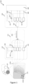
- Figure 1 shows a schematic diagram of a sensor-based communication apparatus 100 according to an embodiment of the present disclosure.
- the apparatus 100 includes a communication medium 110 and a receiver 130.
- the communication medium 110 includes a layer of electronic skin shown in Figure 1 covering or worn by a robotic hand.
- the receiver 130 further includes a plurality of threshold circuit 133 associated with the filters 132, respectively.
- Each threshold circuit 133 is configured to suppress an indication pulse in the corresponding indication signal 400 if the corresponding result of correlation operation is below a correlation threshold value. For example, with an example correlation threshold value of 7 (e.g., if the intermediate signal 300' correlates concurrently with at least seven pulses of the respective signature 200 at a given time point), if the result of a correlation operation for a signature is 6 (i.e., below the correlation threshold value), the indication pulse generated by the corresponding filter is suppressed by the corresponding threshold circuit 133 due to the likelihood of error (i.e., low correlation).
- pulse signatures 200 of the same pulse positions and different (e.g., opposite) pulse polarities may be used by each sensor node 112 to indicate respective two states in the corresponding sensory signal 113a.
- the polarity of each pulse, or "pulse polarity” means the potential of the pulse, either the positive voltage potential ("Vdd") or the negative voltage potential ("Vss").
- Vdd positive voltage potential
- Vss negative voltage potential
- the number of filters 132 should match the total number of unique pulse signatures 200 assigned to the sensor nodes 112.
- the FA sensors 113 are configured to respond only to dynamic deformation of the conductive fabric 111 and to be insensitive to static forces. Each FA sensor 113 is configured to indicate a first state of pressure increase and a second state of press decrease in its sensory signal 113a. That is to say, for each FA sensor 113, the sensory signal 113a generated by the FA sensor 113 has the first and second states.
- the corresponding sensor node 112 of each FA sensor 113 is associated with first and second unique pulse signatures 200 to indicate the first and second states of the sensory signal 113a, respectively.
- the firmware model in the sensor node 112 for the FA behaviour causes the microcontroller 116 to generate and transmit the first and second unique pulse signatures 200 according to the state of the corresponding sensory signal 113a.
- Each sensor node 112 is triggered, upon receipt of the corresponding sensory signal 113a in the first state, to transmit the associated first unique pulse signature 200, and upon receipt of the corresponding sensory signal 113a in the second state, to transmit the associated second unique pulse signature 200 independently through the transmission medium.
- the microcontroller 116 is caused by the firmware model to generate and transmit the first unique pulse signature 200 for each increment of more than 50 mV detected in the corresponding sensory signal 113a, and to generate and transmit the second unique pulse signature 200 for each decrement of more than 50 mV detected in the corresponding sensory signal 113a.
- the sensor node 112 of each FA sensor 113 is able to indicate to the receiver 130 the state of the sensory signal 113a (increase and decrease of pressure).
- the first and second unique pulse signatures 200 of each sensor node 112 may have different (e.g., opposite) pulse polarities.
- the SA sensors 113 are further configured to respond to static pressure and to be insensitive to dynamic deformation of the conductive fabric 111.
- Each SA sensor 113 is configured to indicate a current value of static pressure in its sensory signal 113a, and the corresponding sensor node 112 transmits the corresponding signature 200 at a frequency dependent on the current value.
- the signature transmission frequency is in a positive relative to the current value of detected static pressure in the sensory signal 113a. That is, the higher the current value of detected pressure, the shorter the interval between two corresponding consecutive signature transmissions.
- the firmware model for SA behaviour causes the microcontroller 116 to generate and transmit multiple instances of the respective unique pulse signature 200 with an interval proportional to the 8 point averaged ADC digital value.
- Each sensor node 112 may, in other arrangements, be associated with a sensor 113 of any type, and be configured to transmit consecutive instances of an associated unique pulse signature 200 to indicate, by a corresponding interval between current and previous ones of the associated unique pulse signature 200, a current value of the sensory signal 113a generated by the sensor 113.
- each sensor node 112 is, in the example of Figures 11A and 11B , configured by way of firmware to recognise and be associated with the respective sensor 113. That is, the sensor node 112 chooses a mode of operation based on the type or configuration of the associated sensor 113 (SA or FA). Whilst the FA and SA sensors 112 are described to be different types of sensors, they may be implemented using the same component (e.g., a piezoresistive element). In such a case, whether the sensor 112 is to function or be treated as an FA sensor or an SA sensor can be determined by the firmware of the respective sensor node 113.
- SA type or configuration of the associated sensor 113
- each sensor node 112 is configured to transmit another associated unique pulse signature 200 independently through the transmission medium to indicate an internal state of the respective sensor node.
- the sensor node 112 may be associated with one or more additional unique pulse signatures for each additional internal state to be reported.
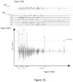
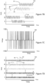
- Figure 11A shows a plot of dynamic force increases and decreases sensed by one of the FA sensors 113 in relation to a load cell over time, and a plot of static forces detected by one of the SA sensors 113 against the load cell over time, obtained based on the corresponding indication signals 400 shown in Figure 11B .
- the detected states of force increase and force decrease are marked by opposite respective triangular symbols.
- the values of detected static force are marked by respective square symbols.
- the SA sensors 113 can accurately detect static force and indicate the respective detected values in their respective sensory signals 113a.
- the FA sensors 113 can accurately detect dynamic force and indicate the detected states of force increase and force decrease in their sensory signals 113a.
- Figures 12A and 12C show photographic representations of flexible pressure sensors implemented with heterogeneous transduction profiles developed by altering the Young's modulus of elastomers used to construct the micro-pyramidal piezo-resistive sensors.
- Figure 12B shows a plot of resistance values versus pressures. This allows sensors of various tactile sensitivities to be distributed spatially on the same substrate (i.e., the conductive fabric 111). With such a construction, the sensors can be made to be sensitive to both light touches and higher loads without saturation. The wide dynamic pressure range enables continued pressure detection under typical manipulation forces when gripping an object.
- Figure 13A shows a photographic representation of an array of pressure and temperature sensors on a robotic effector in the shape of a human hand in association with a cup of hot liquid.
- Figure 13B shows a plot of resistivity versus temperature obtained using the temperature sensors of Figure 13A.
- Figure 13C shows an optical microscopic image of one of the temperature sensors of Figure 13A .
- the temperature sensors are flexible resistive sensors implemented on a single substrate (i.e. conductive fabric).
- the temperature sensor is designed to have a main sensitivity range from 20°C to 50°C, which similar to the cold receptor afferents in human skin.
- the associated sensor node transmits the unique pulse signature at a reduced frequency (i.e., increased interval) as the detected temperature rises above 25°C (see Figure 13D).
- Figure 13E shows an example arrangement of resistive pressure and temperature sensors on a single substrate (i.e., conductive fabric).
- Figures 14A and 14B show diagrams in relation to the application of Figure 13A (holding a cup containing hot liquid).
- Figure 14A shows a diagram of indication signals versus time obtained from pulse signatures transmitted by the temperature and pressure (SA) sensors.
- Figure 14B shows a diagram of stimulation detection based on the indications signals shown in Figure 14A . It can be seen from these figures that simultaneous or near simultaneous detection of tactile and thermal stimuli by the SA and temperature sensors can be achieved.
- the FA sensors 113 can be employed by, for example, a robotic effector to detect slippage of an object held by the effector.
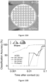
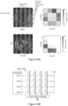
- Figure 15A (part i) shows a spatiotemporal representation or pattern of tactile stimuli detected by the FA sensors 113 over time, with the FA sensors 113 provided on the effector.
- a spiking convolutional network is implemented to compute the magnitude and direction of slippage in an event-driven manner. As slippage of the object starts to occur, stimulus detection by the FA sensors 113 triggers the computation of movement to estimate the onset of slippage.
- movement estimates can be calculated immediately upon slippage onset, and the downward movement of the object can be accurately identified.
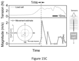
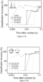
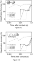
- Figure 15C shows that the same implementation can be used to detect the slippage of a needle with 1 ms of latency.
- the directional estimates show higher deviations due to the smaller number of stimulated FA sensors 112 and the reduced contact area. Higher sensor densities are thus required for dextrous manipulation tasks of varying object form factor.
- an acrylic disk of 1cm diameter and a needle of 0.8 mm diameter is held respectively and vertically between two flat opposing surfaces of a bench vice.
- An array of 80 pressure sensors (similar to the one in Figure 14A but without the thermal sensors), are arranged to interface with a corresponding array of sensor nodes mimicking FA behaviour.
- the sensors are pasted on one of the surfaces of the vice.
- a thread connects the object to a load cell.
- a separate thread is connected to the opposite side of the load cell and adapted to be pulled to cause slippage of the object from the vice.
- Data generated by the 80 sensor nodes is sampled together with an analog output of the load cell at 125 MHz using an oscilloscope (Picoscope 3406D). Computation of slip detection is processed offline in MATLAB.
- the global movement estimate (part iii, Figure 15A ) is obtained as the moving average (exponential kernel of 5 ms time constant) for all the local movement estimates.
- the conductive fabric 111 is made of a conductive polymer (e.g., PEDOT:PSS).
- a conductive polymer e.g., PEDOT:PSS
- any conductive medium e.g., conductive knitted wires, carbon based nanomaterials, metal nanowires, metal films, and metal wires
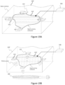
- the conductive fabric 111 of this example is electrically connected to the sensor nodes 112. It is to be emphasized that the conductive fabric 111 is just one possible form of the conductive medium. Some other example forms are described below with reference to Figures 19 and 20 .
Landscapes
- Engineering & Computer Science (AREA)
- General Engineering & Computer Science (AREA)
- Theoretical Computer Science (AREA)
- Physics & Mathematics (AREA)
- Human Computer Interaction (AREA)
- General Physics & Mathematics (AREA)
- General Health & Medical Sciences (AREA)
- Health & Medical Sciences (AREA)
- Biomedical Technology (AREA)
- Mechanical Engineering (AREA)
- Computing Systems (AREA)
- Neurosurgery (AREA)
- Neurology (AREA)
- Dermatology (AREA)
- Robotics (AREA)
- Computer Networks & Wireless Communication (AREA)
- Signal Processing (AREA)
- Evolutionary Computation (AREA)
- Mathematical Physics (AREA)
- Software Systems (AREA)
- Life Sciences & Earth Sciences (AREA)
- Molecular Biology (AREA)
- Artificial Intelligence (AREA)
- Data Mining & Analysis (AREA)
- Computational Linguistics (AREA)
- Biophysics (AREA)
- Medical Informatics (AREA)
- Arrangements For Transmission Of Measured Signals (AREA)
- Measuring And Recording Apparatus For Diagnosis (AREA)
Claims (15)
- Appareil de communication basé sur des capteurs (100) comprenant :une pluralité de nœuds de capteur (112) associés à des signatures impulsionnelles uniques respectives (200) et adaptés à communiquer avec des capteurs (113) respectifs ;dans lequel chaque nœud de capteur de la pluralité de nœuds de capteur (112) est configuré pour recevoir un signal sensoriel (113a) correspondant qui est généré par un capteur correspondant en réponse à un stimulus (113b) respectif,dans lequel chacun desdits nœuds de capteur (112) est configuré, dès réception du signal sensoriel (113a) correspondant, pour transmettre de manière indépendante et asynchrone la signature impulsionnelle unique (200) associée par le biais d'un support de transmission (110) partagé par les nœuds de capteur (112), les signatures impulsionnelles uniques (200) transmises par les nœuds de capteur (112) étant une représentation d'un événement de stimulation associé aux stimuli (113b) détectés par les capteurs correspondants (113),dans lequel chacun des nœuds de capteur (112) est associé à une signature impulsionnelle unique (200) donnée comprenant une pluralité d'impulsions, dans lequel l'intervalle entre chaque combinaison possible de deux impulsions parmi ladite pluralité d'impulsions représente un intervalle entre impulsions de ladite signature d'impulsion donnée, etdans lequel chaque intervalle entre impulsions de la signature impulsionnelle unique (200) de chacun des nœuds de capteur (112) présente une durée unique parmi les durées de tous les intervalles entre impulsions des signatures impulsionnelles uniques (200) de la totalité des nœuds de capteur (112).
- Appareil de communication basé sur des capteurs (100) selon la revendication 1, dans lequel la signature impulsionnelle unique (200) présente huit ou dix impulsions.
- Appareil de communication basé sur des capteurs (100) selon la revendication 1 ou 2, dans lequel la signature impulsionnelle unique (200) d'un des nœuds de capteur (112) présente un premier nombre d'impulsions et la signature impulsionnelle unique (200) d'un autre des nœuds de capteur (112) présente un deuxième nombre d'impulsions différent du premier nombre.
- Appareil de communication basé sur des capteurs (100) selon l'une quelconque des revendications 1 à 3, dans lequel la signature impulsionnelle unique (200) d'un des nœuds de capteur (112) présente une première durée de signature et la signature impulsionnelle unique (200) d'un autre des nœuds de capteur (112) présente une deuxième durée de signature différente de la première durée de signature.
- Appareil de communication basé sur des capteurs (100) selon l'une quelconque des revendications 1 à 4, comprenant en outre :
un récepteur configuré pour recevoir, par le biais du support de transmission (110), un signal entrant concernant les signatures impulsionnelles uniques (200) transmises, pour corréler la signature impulsionnelle unique (200) associée de chaque nœud de capteur (112) avec un signal intermédiaire concernant le signal entrant, et pour fournir des signaux d'indication indiquant des heures respectives de déclenchement des nœuds de capteur (112) en fonction d'un résultat de corrélation pour une représentation de l'événement de stimulation. - Appareil de communication basé sur des capteurs (100) selon l'une quelconque des revendications 1 à 5, dans lequel le support de transmission (110) inclut un support conducteur (111) ; et dans lequel les nœuds de capteur (112) sont répartis le long du support conducteur (111) et couplés électriquement entre eux par le biais du support conducteur (111).
- Appareil de communication basé sur des capteurs (100) selon la revendication 6, dans lequel les nœuds de capteur (112) sont incorporés dans le support conducteur (111).
- Appareil de communication basé sur des capteurs (100) selon la revendication 6 ou 7, dans lequel le support conducteur (111) est élastique et souple.
- Appareil de communication basé sur des capteurs (100) selon l'une quelconque des revendications 6 à 8, dans lequel le support conducteur (111) se présente sous une forme de maillage ou une forme plane.
- Appareil de communication basé sur des capteurs (100) selon la revendication 6 ou 7, dans lequel le support conducteur (111) inclut au moins un matériau parmi un tissu conducteur (111), un matériau conducteur à conductance interne, un substrat conducteur, un solide conducteur, un gel conducteur et un fluide conducteur.
- Appareil de communication basé sur des capteurs (100) selon une quelconque revendication précédente, dans lequel chaque nœud de capteur (112) est en outre associé à une signature impulsionnelle unique (200) supplémentaire, chaque nœud de capteur (112) étant déclenché, dès réception du signal sensoriel (113a) correspondant dans un premier état, pour transmettre la signature impulsionnelle unique (200) associée et, dès réception du signal sensoriel (113a) correspondant dans un deuxième état, pour transmettre de manière indépendante la signature impulsionnelle unique (200) supplémentaire associée par le biais du support de transmission (110).
- Appareil de communication basé sur des capteurs (100) selon l'une quelconque des revendications 1 à 10, dans lequel chaque nœud de capteur (112) est en outre associé à une signature impulsionnelle unique (200) supplémentaire et dans lequel chaque nœud de capteur (112) est configuré pour transmettre de manière indépendante la signature impulsionnelle unique (200) supplémentaire associée par le biais du support de transmission (110) pour indiquer un état interne du nœud de capteur (112) respectif.
- Appareil de communication basé sur des capteurs (100) selon une quelconque revendication précédente, dans lequel chaque nœud de capteur (112) est en outre associé à une signature impulsionnelle unique (200) supplémentaire et dans lequel les signatures impulsionnelles uniques (200) de chaque nœud de capteur (112) présentent des polarités d'impulsion différentes.
- Appareil de communication basé sur des capteurs (100) selon une quelconque revendication précédente, dans lequel la représentation de l'événement de stimulation est une représentation spatiotemporelle.
- Procédé de communication basé sur des capteurs comprenant :la réception, par chaque nœud de capteur d'une pluralité de nœuds de capteur (112), d'un signal sensoriel (113a) généré par un capteur (113) correspondant en réponse à une stimulation (113b) respective, etdès réception du signal sensoriel (113a), la transmission de manière indépendante et asynchrone, par un nœud de capteur respectif de la pluralité de nœuds de capteur (112), d'une signature impulsionnelle unique (200) associée par le biais d'un support de transmission (110) partagé par les nœuds de capteur (112), les signatures impulsionnelles uniques (200) transmises par les nœuds de capteur (112) étant une représentation d'un événement de stimulation associé aux stimuli détectés par les capteurs (113) correspondants ;dans lequel chacun des nœuds de capteur (112) est associé à une signature impulsionnelle unique donnée comprenant une pluralité d'impulsions,dans lequel l'intervalle entre chaque combinaison possible de deux impulsions parmi ladite pluralité d'impulsions représente un intervalle entre impulsions de ladite signature impulsionnelle donnée, etdans lequel chaque intervalle entre impulsions de la signature impulsionnelle unique (200) de chacun des nœuds de capteur (112) présente une durée unique parmi les durées de la totalité des intervalles entre impulsions des signatures impulsionnelles uniques de la totalité des nœuds de capteur.
Applications Claiming Priority (2)
| Application Number | Priority Date | Filing Date | Title |
|---|---|---|---|
| SG10201710041S | 2017-12-04 | ||
| PCT/SG2018/050590 WO2019112516A1 (fr) | 2017-12-04 | 2018-12-03 | Appareil et procédé de communication orientés capteurs, et support de communication |
Publications (3)
| Publication Number | Publication Date |
|---|---|
| EP3721323A1 EP3721323A1 (fr) | 2020-10-14 |
| EP3721323A4 EP3721323A4 (fr) | 2021-12-15 |
| EP3721323B1 true EP3721323B1 (fr) | 2025-04-16 |
Family
ID=66749897
Family Applications (1)
| Application Number | Title | Priority Date | Filing Date |
|---|---|---|---|
| EP18886967.1A Active EP3721323B1 (fr) | 2017-12-04 | 2018-12-03 | Appareil et procédé de communication basés sur des capteurs |
Country Status (4)
| Country | Link |
|---|---|
| US (1) | US11474601B2 (fr) |
| EP (1) | EP3721323B1 (fr) |
| JP (1) | JP7202025B2 (fr) |
| WO (1) | WO2019112516A1 (fr) |
Families Citing this family (5)
| Publication number | Priority date | Publication date | Assignee | Title |
|---|---|---|---|---|
| US11491651B2 (en) * | 2020-03-03 | 2022-11-08 | The Boeing Company | Data communication network with gigabit plastic optical fiber for robotic arm system |
| US12257727B2 (en) | 2020-06-15 | 2025-03-25 | National University Of Singapore | Event-driven visual-tactile sensing and learning for robots |
| CN114370891A (zh) * | 2021-12-30 | 2022-04-19 | 菱感能源科技(苏州)有限公司 | 一种在线监测数据的温湿度传感器故障诊断装置 |
| TW202344959A (zh) * | 2022-05-03 | 2023-11-16 | 神煜電子股份有限公司 | 光學壓力感測裝置及其應用 |
| US20240394070A1 (en) * | 2023-05-23 | 2024-11-28 | GM Global Technology Operations LLC | Characterizing notification distinctiveness for a finite-state machine modeled system |
Family Cites Families (13)
| Publication number | Priority date | Publication date | Assignee | Title |
|---|---|---|---|---|
| CA2371343A1 (fr) | 1999-05-21 | 2000-11-30 | Ralph J. Koerner | Systeme d'identification pour surveiller la presence/l'absence des elements d'un ensemble defini |
| AU2003231277B2 (en) | 2000-10-27 | 2007-02-01 | Lightwaves Systems, Inc. | High bandwidth data transport system |
| JP2004007448A (ja) * | 2001-10-12 | 2004-01-08 | Serukurosu:Kk | 通信装置 |
| JP2005323205A (ja) * | 2004-05-10 | 2005-11-17 | Sharp Corp | 無線信号送信装置および無線信号受信装置ならびに無線信号伝送システム |
| US20100036207A1 (en) * | 2008-07-24 | 2010-02-11 | Michael Zack Eckblad | Relative response system including reprogramming capability for autonomous or interrelated stimulus and sensor systems for measuring biological response data relative to either an absolute reference and/or relative to other biological response |
| WO2010124021A2 (fr) * | 2009-04-21 | 2010-10-28 | Arizona Board Of Regents For And On Behalf Of Arizona State University | Interface de communication pour stimulation sensorielle |
| US9311593B2 (en) | 2010-03-26 | 2016-04-12 | Brain Corporation | Apparatus and methods for polychronous encoding and multiplexing in neuronal prosthetic devices |
| US9405975B2 (en) | 2010-03-26 | 2016-08-02 | Brain Corporation | Apparatus and methods for pulse-code invariant object recognition |
| JP5687467B2 (ja) * | 2010-10-12 | 2015-03-18 | 国立大学法人東北大学 | 触覚センサシステム |
| US8988386B2 (en) * | 2012-01-27 | 2015-03-24 | Sony Corporation | Sensor managed apparatus, method and computer program product |
| JP6644296B2 (ja) * | 2014-12-19 | 2020-02-12 | 国立大学法人 名古屋工業大学 | 波形選択フィルタを用いた通話システム、通信端末 |
| KR101781542B1 (ko) | 2015-02-27 | 2017-09-27 | 서울대학교산학협력단 | 피부 보철용 신축성 전자장치 |
| KR102307055B1 (ko) * | 2015-04-28 | 2021-10-01 | 삼성전자주식회사 | 이벤트 기반 센서의 출력에 기초하여 정적 패턴을 추출하는 방법 및 장치 |
-
2018
- 2018-12-03 EP EP18886967.1A patent/EP3721323B1/fr active Active
- 2018-12-03 WO PCT/SG2018/050590 patent/WO2019112516A1/fr not_active Ceased
- 2018-12-03 US US16/769,060 patent/US11474601B2/en active Active
- 2018-12-03 JP JP2020548852A patent/JP7202025B2/ja active Active
Also Published As
| Publication number | Publication date |
|---|---|
| JP2021506194A (ja) | 2021-02-18 |
| WO2019112516A1 (fr) | 2019-06-13 |
| EP3721323A4 (fr) | 2021-12-15 |
| US20200333881A1 (en) | 2020-10-22 |
| US11474601B2 (en) | 2022-10-18 |
| JP7202025B2 (ja) | 2023-01-11 |
| EP3721323A1 (fr) | 2020-10-14 |
Similar Documents
| Publication | Publication Date | Title |
|---|---|---|
| EP3721323B1 (fr) | Appareil et procédé de communication basés sur des capteurs | |
| Lee et al. | A neuro-inspired artificial peripheral nervous system for scalable electronic skins | |
| US12504843B2 (en) | Position indicator, position detecting device, position detecting circuit, and position detecting method | |
| Navaraj et al. | Fingerprint‐enhanced capacitive‐piezoelectric flexible sensing skin to discriminate static and dynamic tactile stimuli | |
| Chun et al. | A self‐powered sensor mimicking slow‐and fast‐adapting cutaneous mechanoreceptors | |
| CN103105949B (zh) | 用于多区域输入装置中的电力节约的方法和系统 | |
| US8272278B2 (en) | Enhancements to improve the function of a biomimetic tactile sensor | |
| Hughes et al. | Texture recognition and localization in amorphous robotic skin | |
| Speeter | A tactile sensing system for robotic manipulation | |
| Prakash et al. | Novel force myography sensor to measure muscle contractions for controlling hand prostheses | |
| Hirai et al. | Fabric interface with proximity and tactile sensation for human-robot interaction | |
| Schurmann et al. | A modular high-speed tactile sensor for human manipulation research | |
| Reinschmidt et al. | Realtime hand-gesture recognition based on novel charge variation sensor and IMU | |
| Zhang et al. | Vibecheck: Using active acoustic tactile sensing for contact-rich manipulation | |
| Backus et al. | Robust resonant frequency-based contact detection with applications in robotic reaching and grasping | |
| Gupta et al. | A neuromorphic approach to tactile texture recognition | |
| JP7374188B2 (ja) | 触覚センサ、それを用いた触覚刺激検知方法、ロボット皮膚、及びそれを含むロボット | |
| McCammon et al. | Tactile sensing and control for the Utah/MIT hand | |
| Dahiya et al. | Biomimetic tactile sensing | |
| Mittendorfer | From a multi-modal intelligent cell to a self-organizing robotic skin-realizing self and enriching robot tactile interaction | |
| Lorussi et al. | Wearable sensing garment for posture detection, rehabilitation and tele-medicine | |
| Teja et al. | Fault tolerant tactile sensor arrays for prosthesis | |
| Kim et al. | A flexible fingertip tactile sensor | |
| Rupavatharam | Omnidirectional and blindspot-free pre-touch sensing systems | |
| Lastra | OLLI-PEKKA KARJALAINEN CAPACITIVE MEASUREMENT FOR ROBOT Z-AXIS POSITION |
Legal Events
| Date | Code | Title | Description |
|---|---|---|---|
| STAA | Information on the status of an ep patent application or granted ep patent |
Free format text: STATUS: THE INTERNATIONAL PUBLICATION HAS BEEN MADE |
|
| PUAI | Public reference made under article 153(3) epc to a published international application that has entered the european phase |
Free format text: ORIGINAL CODE: 0009012 |
|
| STAA | Information on the status of an ep patent application or granted ep patent |
Free format text: STATUS: REQUEST FOR EXAMINATION WAS MADE |
|
| 17P | Request for examination filed |
Effective date: 20200806 |
|
| AK | Designated contracting states |
Kind code of ref document: A1 Designated state(s): AL AT BE BG CH CY CZ DE DK EE ES FI FR GB GR HR HU IE IS IT LI LT LU LV MC MK MT NL NO PL PT RO RS SE SI SK SM TR |
|
| AX | Request for extension of the european patent |
Extension state: BA ME |
|
| DAV | Request for validation of the european patent (deleted) | ||
| DAX | Request for extension of the european patent (deleted) | ||
| RIC1 | Information provided on ipc code assigned before grant |
Ipc: H04L 29/08 20060101ALI20210805BHEP Ipc: H04B 14/02 20060101ALI20210805BHEP Ipc: G06N 3/04 20060101ALI20210805BHEP Ipc: B25J 13/08 20060101ALI20210805BHEP Ipc: G06F 3/01 20060101AFI20210805BHEP |
|
| A4 | Supplementary search report drawn up and despatched |
Effective date: 20211111 |
|
| RIC1 | Information provided on ipc code assigned before grant |
Ipc: H04L 29/08 20060101ALI20211105BHEP Ipc: H04B 14/02 20060101ALI20211105BHEP Ipc: G06N 3/04 20060101ALI20211105BHEP Ipc: B25J 13/08 20060101ALI20211105BHEP Ipc: G06F 3/01 20060101AFI20211105BHEP |
|
| STAA | Information on the status of an ep patent application or granted ep patent |
Free format text: STATUS: EXAMINATION IS IN PROGRESS |
|
| 17Q | First examination report despatched |
Effective date: 20230713 |
|
| REG | Reference to a national code |
Ref legal event code: R079 Free format text: PREVIOUS MAIN CLASS: G06F0003010000 Ref country code: DE Ref legal event code: R079 Ref document number: 602018081212 Country of ref document: DE Free format text: PREVIOUS MAIN CLASS: G06F0003010000 Ipc: H04L0067120000 |
|
| GRAP | Despatch of communication of intention to grant a patent |
Free format text: ORIGINAL CODE: EPIDOSNIGR1 |
|
| STAA | Information on the status of an ep patent application or granted ep patent |
Free format text: STATUS: GRANT OF PATENT IS INTENDED |
|
| RIC1 | Information provided on ipc code assigned before grant |
Ipc: G06F 3/01 20060101ALI20241101BHEP Ipc: G06N 3/049 20230101ALI20241101BHEP Ipc: H04B 14/02 20060101ALI20241101BHEP Ipc: B25J 13/08 20060101ALI20241101BHEP Ipc: H04L 67/12 20220101AFI20241101BHEP |
|
| INTG | Intention to grant announced |
Effective date: 20241121 |
|
| GRAS | Grant fee paid |
Free format text: ORIGINAL CODE: EPIDOSNIGR3 |
|
| GRAA | (expected) grant |
Free format text: ORIGINAL CODE: 0009210 |
|
| STAA | Information on the status of an ep patent application or granted ep patent |
Free format text: STATUS: THE PATENT HAS BEEN GRANTED |
|
| AK | Designated contracting states |
Kind code of ref document: B1 Designated state(s): AL AT BE BG CH CY CZ DE DK EE ES FI FR GB GR HR HU IE IS IT LI LT LU LV MC MK MT NL NO PL PT RO RS SE SI SK SM TR |
|
| REG | Reference to a national code |
Ref country code: GB Ref legal event code: FG4D |
|
| REG | Reference to a national code |
Ref country code: CH Ref legal event code: EP Ref country code: DE Ref legal event code: R096 Ref document number: 602018081212 Country of ref document: DE |
|
| REG | Reference to a national code |
Ref country code: IE Ref legal event code: FG4D |
|
| REG | Reference to a national code |
Ref country code: NL Ref legal event code: MP Effective date: 20250416 |
|
| PG25 | Lapsed in a contracting state [announced via postgrant information from national office to epo] |
Ref country code: NL Free format text: LAPSE BECAUSE OF FAILURE TO SUBMIT A TRANSLATION OF THE DESCRIPTION OR TO PAY THE FEE WITHIN THE PRESCRIBED TIME-LIMIT Effective date: 20250416 |
|
| REG | Reference to a national code |
Ref country code: AT Ref legal event code: MK05 Ref document number: 1786624 Country of ref document: AT Kind code of ref document: T Effective date: 20250416 |
|
| PG25 | Lapsed in a contracting state [announced via postgrant information from national office to epo] |
Ref country code: ES Free format text: LAPSE BECAUSE OF FAILURE TO SUBMIT A TRANSLATION OF THE DESCRIPTION OR TO PAY THE FEE WITHIN THE PRESCRIBED TIME-LIMIT Effective date: 20250416 Ref country code: FI Free format text: LAPSE BECAUSE OF FAILURE TO SUBMIT A TRANSLATION OF THE DESCRIPTION OR TO PAY THE FEE WITHIN THE PRESCRIBED TIME-LIMIT Effective date: 20250416 Ref country code: PT Free format text: LAPSE BECAUSE OF FAILURE TO SUBMIT A TRANSLATION OF THE DESCRIPTION OR TO PAY THE FEE WITHIN THE PRESCRIBED TIME-LIMIT Effective date: 20250818 |
|
| REG | Reference to a national code |
Ref country code: LT Ref legal event code: MG9D |
|
| PG25 | Lapsed in a contracting state [announced via postgrant information from national office to epo] |
Ref country code: GR Free format text: LAPSE BECAUSE OF FAILURE TO SUBMIT A TRANSLATION OF THE DESCRIPTION OR TO PAY THE FEE WITHIN THE PRESCRIBED TIME-LIMIT Effective date: 20250717 Ref country code: NO Free format text: LAPSE BECAUSE OF FAILURE TO SUBMIT A TRANSLATION OF THE DESCRIPTION OR TO PAY THE FEE WITHIN THE PRESCRIBED TIME-LIMIT Effective date: 20250716 |
|
| PG25 | Lapsed in a contracting state [announced via postgrant information from national office to epo] |
Ref country code: PL Free format text: LAPSE BECAUSE OF FAILURE TO SUBMIT A TRANSLATION OF THE DESCRIPTION OR TO PAY THE FEE WITHIN THE PRESCRIBED TIME-LIMIT Effective date: 20250416 |
|
| PG25 | Lapsed in a contracting state [announced via postgrant information from national office to epo] |
Ref country code: BG Free format text: LAPSE BECAUSE OF FAILURE TO SUBMIT A TRANSLATION OF THE DESCRIPTION OR TO PAY THE FEE WITHIN THE PRESCRIBED TIME-LIMIT Effective date: 20250416 |
|
| PG25 | Lapsed in a contracting state [announced via postgrant information from national office to epo] |
Ref country code: HR Free format text: LAPSE BECAUSE OF FAILURE TO SUBMIT A TRANSLATION OF THE DESCRIPTION OR TO PAY THE FEE WITHIN THE PRESCRIBED TIME-LIMIT Effective date: 20250416 |
|
| PG25 | Lapsed in a contracting state [announced via postgrant information from national office to epo] |
Ref country code: AT Free format text: LAPSE BECAUSE OF FAILURE TO SUBMIT A TRANSLATION OF THE DESCRIPTION OR TO PAY THE FEE WITHIN THE PRESCRIBED TIME-LIMIT Effective date: 20250416 |
|
| PG25 | Lapsed in a contracting state [announced via postgrant information from national office to epo] |
Ref country code: RS Free format text: LAPSE BECAUSE OF FAILURE TO SUBMIT A TRANSLATION OF THE DESCRIPTION OR TO PAY THE FEE WITHIN THE PRESCRIBED TIME-LIMIT Effective date: 20250716 |
|
| PG25 | Lapsed in a contracting state [announced via postgrant information from national office to epo] |
Ref country code: IS Free format text: LAPSE BECAUSE OF FAILURE TO SUBMIT A TRANSLATION OF THE DESCRIPTION OR TO PAY THE FEE WITHIN THE PRESCRIBED TIME-LIMIT Effective date: 20250816 |
|
| PG25 | Lapsed in a contracting state [announced via postgrant information from national office to epo] |
Ref country code: LV Free format text: LAPSE BECAUSE OF FAILURE TO SUBMIT A TRANSLATION OF THE DESCRIPTION OR TO PAY THE FEE WITHIN THE PRESCRIBED TIME-LIMIT Effective date: 20250416 |
|
| PG25 | Lapsed in a contracting state [announced via postgrant information from national office to epo] |
Ref country code: DK Free format text: LAPSE BECAUSE OF FAILURE TO SUBMIT A TRANSLATION OF THE DESCRIPTION OR TO PAY THE FEE WITHIN THE PRESCRIBED TIME-LIMIT Effective date: 20250416 Ref country code: SM Free format text: LAPSE BECAUSE OF FAILURE TO SUBMIT A TRANSLATION OF THE DESCRIPTION OR TO PAY THE FEE WITHIN THE PRESCRIBED TIME-LIMIT Effective date: 20250416 |
|
| REG | Reference to a national code |
Ref country code: DE Ref legal event code: R097 Ref document number: 602018081212 Country of ref document: DE |
|
| PG25 | Lapsed in a contracting state [announced via postgrant information from national office to epo] |
Ref country code: CZ Free format text: LAPSE BECAUSE OF FAILURE TO SUBMIT A TRANSLATION OF THE DESCRIPTION OR TO PAY THE FEE WITHIN THE PRESCRIBED TIME-LIMIT Effective date: 20250416 |
|
| PG25 | Lapsed in a contracting state [announced via postgrant information from national office to epo] |
Ref country code: EE Free format text: LAPSE BECAUSE OF FAILURE TO SUBMIT A TRANSLATION OF THE DESCRIPTION OR TO PAY THE FEE WITHIN THE PRESCRIBED TIME-LIMIT Effective date: 20250416 |
|
| PG25 | Lapsed in a contracting state [announced via postgrant information from national office to epo] |
Ref country code: SK Free format text: LAPSE BECAUSE OF FAILURE TO SUBMIT A TRANSLATION OF THE DESCRIPTION OR TO PAY THE FEE WITHIN THE PRESCRIBED TIME-LIMIT Effective date: 20250416 Ref country code: RO Free format text: LAPSE BECAUSE OF FAILURE TO SUBMIT A TRANSLATION OF THE DESCRIPTION OR TO PAY THE FEE WITHIN THE PRESCRIBED TIME-LIMIT Effective date: 20250416 |
|
| PG25 | Lapsed in a contracting state [announced via postgrant information from national office to epo] |
Ref country code: IT Free format text: LAPSE BECAUSE OF FAILURE TO SUBMIT A TRANSLATION OF THE DESCRIPTION OR TO PAY THE FEE WITHIN THE PRESCRIBED TIME-LIMIT Effective date: 20250416 |
|
| PLBE | No opposition filed within time limit |
Free format text: ORIGINAL CODE: 0009261 |
|
| STAA | Information on the status of an ep patent application or granted ep patent |
Free format text: STATUS: NO OPPOSITION FILED WITHIN TIME LIMIT |
|
| REG | Reference to a national code |
Ref country code: CH Ref legal event code: L10 Free format text: ST27 STATUS EVENT CODE: U-0-0-L10-L00 (AS PROVIDED BY THE NATIONAL OFFICE) Effective date: 20260225 |
|
| 26N | No opposition filed |
Effective date: 20260119 |
|
| PGFP | Annual fee paid to national office [announced via postgrant information from national office to epo] |
Ref country code: GB Payment date: 20260106 Year of fee payment: 8 |
|
| PGFP | Annual fee paid to national office [announced via postgrant information from national office to epo] |
Ref country code: DE Payment date: 20251230 Year of fee payment: 8 |