EP3721514B1 - Adaptateur de montage de composants électrotechniques - Google Patents
Adaptateur de montage de composants électrotechniques Download PDFInfo
- Publication number
- EP3721514B1 EP3721514B1 EP18811534.9A EP18811534A EP3721514B1 EP 3721514 B1 EP3721514 B1 EP 3721514B1 EP 18811534 A EP18811534 A EP 18811534A EP 3721514 B1 EP3721514 B1 EP 3721514B1
- Authority
- EP
- European Patent Office
- Prior art keywords
- adapter
- mounting
- fastening means
- component
- front plate
- Prior art date
- Legal status (The legal status is an assumption and is not a legal conclusion. Google has not performed a legal analysis and makes no representation as to the accuracy of the status listed.)
- Active
Links
Images

Classifications
-
- H—ELECTRICITY
- H05—ELECTRIC TECHNIQUES NOT OTHERWISE PROVIDED FOR
- H05K—PRINTED CIRCUITS; CASINGS OR CONSTRUCTIONAL DETAILS OF ELECTRIC APPARATUS; MANUFACTURE OF ASSEMBLAGES OF ELECTRICAL COMPONENTS
- H05K7/00—Constructional details common to different types of electric apparatus
- H05K7/02—Arrangements of circuit components or wiring on supporting structure
- H05K7/023—Stackable modules
-
- H—ELECTRICITY
- H01—ELECTRIC ELEMENTS
- H01H—ELECTRIC SWITCHES; RELAYS; SELECTORS; EMERGENCY PROTECTIVE DEVICES
- H01H71/00—Details of the protective switches or relays covered by groups H01H73/00 - H01H83/00
- H01H71/02—Housings; Casings; Bases; Mountings
- H01H71/0264—Mountings or coverplates for complete assembled circuit breakers, e.g. snap mounting in panel
-
- H—ELECTRICITY
- H02—GENERATION; CONVERSION OR DISTRIBUTION OF ELECTRIC POWER
- H02B—BOARDS, SUBSTATIONS OR SWITCHING ARRANGEMENTS FOR THE SUPPLY OR DISTRIBUTION OF ELECTRIC POWER
- H02B1/00—Frameworks, boards, panels, desks, casings; Details of substations or switching arrangements
- H02B1/015—Boards, panels, desks; Parts thereof or accessories therefor
- H02B1/04—Mounting thereon of switches or of other devices in general, the switch or device having, or being without, casing
- H02B1/052—Mounting on rails
-
- H—ELECTRICITY
- H02—GENERATION; CONVERSION OR DISTRIBUTION OF ELECTRIC POWER
- H02B—BOARDS, SUBSTATIONS OR SWITCHING ARRANGEMENTS FOR THE SUPPLY OR DISTRIBUTION OF ELECTRIC POWER
- H02B1/00—Frameworks, boards, panels, desks, casings; Details of substations or switching arrangements
- H02B1/015—Boards, panels, desks; Parts thereof or accessories therefor
- H02B1/04—Mounting thereon of switches or of other devices in general, the switch or device having, or being without, casing
- H02B1/042—Mounting on perforated supports by means of screws or locking members
-
- H—ELECTRICITY
- H02—GENERATION; CONVERSION OR DISTRIBUTION OF ELECTRIC POWER
- H02B—BOARDS, SUBSTATIONS OR SWITCHING ARRANGEMENTS FOR THE SUPPLY OR DISTRIBUTION OF ELECTRIC POWER
- H02B1/00—Frameworks, boards, panels, desks, casings; Details of substations or switching arrangements
- H02B1/26—Casings; Parts thereof or accessories therefor
- H02B1/30—Cabinet-type casings; Parts thereof or accessories therefor
- H02B1/32—Mounting of devices therein
Definitions
- the present disclosure relates to an adapter for mounting electrical components.
- Support rails are metal profile rails to which electrical components such as electrical circuit breakers, relays and terminals are attached in distribution boxes, control cabinets, junction boxes and the like. A component can be pushed onto a support rail from the side or plugged in from the front and clamped in place.
- Support rails can have a shape standardized in accordance with DIN EN 60715 (DIN rail for short).
- DIN EN 60715 DIN rail for short
- An example of such a DIN rail is the so-called top hat rail in accordance with DIN EN 60715 TH35, which has a U-shaped, particularly hat-shaped profile.
- This top hat rail is also known as a DIN rail.
- Components must be specially prepared for mounting on a top hat rail. This is usually the case with components that are intended for mounting in a control cabinet.
- German utility model specification DE 295 08 611 U1 A universal motor protection relay with a molded housing is known, in which a mounting rail is integrated on the front by molding, so that it can be easily connected to an electromagnetic switching device such as a contactor.
- the German disclosure document DE 196 27 295 A1 discloses an amplifier module in which a mounting rail is also formed on the front of the housing in order to be able to attach a contactor to it, for example.
- a bus-capable, sequential connection and/or function module for controlling and/or monitoring technical processes with a block-like structure which has a base unit for attachment to a mounting rail.
- German utility model specification DE 20 2008 015309 U1 discloses a mounting system for mounting electrical and/or mechanical components on a mounting base having at least one mounting base profile or at least one mounting base body.
- German disclosure document DE 197 48 531 A1 describes a consumer branch for switching and protecting a consumer that can be connected in a main circuit for voltages above 100 volts, comprising a branch assembly and a carrier part with first plug connections for connection to a power bus with main power lines, to a data bus and, if necessary, to an auxiliary power bus, wherein the branch assembly can be mechanically adapted to the carrier part and can be contacted with the first plug connections via first mating plug connections.
- the US patent US 6 531 940 B1 describes a combination consisting of a contactor and a soft starter mounted on the contactor.
- the European patent application EP 0 762 581 A1 relates to a device for fastening an electrical device to an adapter, wherein the electrical device is provided with a clamping foot that can be snapped onto a hat-shaped support rail and the support rail is fastened to the adapter in a displaceable and lockable manner in order to facilitate the connection of the electrical device to an electrical connection fixedly arranged on the adapter by moving the support rail intended to support the device in the connection direction of the electrical device.
- German patent specification DE 10 2005 009 993 B3 describes a device adapter with a base part which is provided on its underside with rail receptacles for attachment and contact with current busbars and which carries on its upper side a mounting device which is detachably fastened with connecting means and has two parallel, spaced-apart longitudinal strips for coupling electrical devices or installation units.
- German disclosure document DE 198 36 762 A1 describes a busbar adapter with at least one mounting rail for mounting and/or Fastening of installation devices or the like, which is improved in terms of simple construction, easy manufacture and easy movement of the support rail with secure locking at the desired location.
- an adapter for mounting electrical components is disclosed which is designed in the form of a standardized mounting rail, in particular a top hat rail. On its upper side, the adapter has fastening means for mounting an electrical component, and on its lower side it has fastening means for mounting on the front panel of an electrical component.
- Such an adapter enables a stacked arrangement of electrical components such as switching devices, contactors, motor protection switches or similar components in, for example, a control cabinet. This allows the space available in a control cabinet to be used efficiently compared to arranging the components next to one another on a mounting rail.
- the fastening means on the underside of the adapter have at least one latching hook that is designed to latch into a corresponding latching opening on the front panel of the electrical component.
- the fastening means on the underside of the adapter also have at least one snap hook that is designed to latch into a corresponding latching opening on the front panel of the electrical component.
- a component can be fixed to the adapter by latching and snapping into place.
- the fastening means fix the adapter to the front panel of the electrical component in such a way that the adapter cannot slip on the front panel.
- At least one protrusion may be provided on the top of the adapter.
- the at least one protrusion may In particular, it should be designed to prevent unintentional displacement of a component mounted on the adapter in the mounting plane.
- the fastening means on the underside of the adapter can comprise at least one screw that can be screwed into a corresponding threaded opening on the front panel of an electrical component.
- the fastening means on the top side of the adapter can have at least one thread into which a screw provided on the bottom side of an electrical component can be screwed.
- At least one of the fastening means on the underside of the adapter can be designed such that it can interact with a fastening means provided for mounting an additional component such as an auxiliary switch on the front panel of an electrical component, in particular a latching opening.
- the adapter can be mounted on conventional electrical components such as switching devices that are intended for control cabinet mounting and whose front panel is designed for mounting additional components such as auxiliary switches, for example instead of an additional component.
- the adapter can be made of plastic in particular.
- the adapter can be designed as a plastic injection-molded part or as a stamped or stamped-bent part made of a malleable material such as sheet metal, which means that it can be manufactured with relatively little technical effort.
- the adapter its dimensions in the mounting plane can be adapted to the front panel of at least one electrical component in such a way that no parts of the adapter protrude beyond the front panel protrude.
- This makes it possible, for example, to mount several components directly next to each other on a mounting rail of a control cabinet and to mount an adapter on the front panels of one or more of these components so that further components can be mounted on the corresponding components.
- Components mounted next to each other on the mounting rail can be removed without being hindered by mounted adapters, and components can also be mounted on the mounting rail.
- an electrotechnical component which is designed for mounting on a standardized mounting rail and has at least one latching opening, at least one snap-in opening and/or at least one threaded opening on its front plate for latching or snapping or screwing in at least one latching hook or snap hook or at least one screw of an adapter according to the first aspect and as described herein.
- a second aspect relates to a stacked arrangement of two electrotechnical components, in which an adapter according to the first aspect and as described herein is mounted on the front plate of a first component of the arrangement and a second component with fastening means on its underside is mounted on the fastening means on the top of the adapter.
- Fig. 1 shows a stack arrangement of a first and a second switching device 12 or 14.
- the undersides 12", 14" of the switching devices 12 or 14 are each designed for mounting the switching device 12 or 14 on a top hat rail.
- the front panels 12' or 14' opposite the undersides 12", 14' are designed for mounting a top hat rail adapter 10 and have corresponding openings for this purpose, which in Fig. 1 in the front panel 14'.
- the openings are two latching openings 102', 104' arranged next to one another and two snap-in openings 106', 108' arranged approximately diametrically opposite one another.
- the openings can be provided, for example, to mount an additional component such as an auxiliary switch on the front panel, i.e.
- top hat rail adapter 10 can be fastened to the front panel 12' by means of a screw connection.
- a screw connection for example, one or more screws can be passed through corresponding openings in the adapter and screwed into threaded openings in the front panel of the switching device.
- the stack arrangement of the two switching devices 12 and 14 can, for example, be mounted in a control cabinet on a top-hat rail provided therein in a space-saving manner by plugging the lower switching device 12 with its underside 12" onto the control cabinet top-hat rail and, for example, clamping it to it.
- the stack arrangement can be assembled in various ways: first, the lower switching device 12 can be mounted on the control cabinet top-hat rail, then the top-hat rail adapter 10 on the mounted switching device 12 and finally the upper switching device 14 on the adapter 10.
- the advantage of this type of assembly is that, for example, after the lower switching device 12 has been assembled, it can be wired before continuing with the assembly of the adapter 10 and second switching device 14.
- the pre-assembled stack arrangement of the switching devices 12 and 14 and the adapter 10 can be mounted directly on the control cabinet top-hat rail. This can shorten the assembly process.
- Fig. 2 shows the lower switching device 12 of the stack arrangement of Fig. 1 with the top hat rail adapter 10 mounted on the front plate 12'.
- the two clamping legs 110, 112 on the visible top of the adapter 10 are clamped into corresponding receptacles on the bottom 14" of the upper switching device 14 as with top hat rail mounting, so that a secure attachment of the two switching devices 12 and 14 to each other is ensured.
- the two corresponding receptacles on the underside 12" of the switching device 12 are designated with the reference numerals 110', 112'.
- the clamping legs of, for example, a control cabinet top-hat rail or another adapter can be clamped into these receptacles, for example in a stacked arrangement of three switching devices.
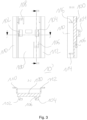
- Fig. 3 shows various views of another embodiment of a top hat rail adapter 10 ⁇ in detail.
- the adapter 10 ⁇ essentially fulfils the same function as the adapter 10 of the Fig. 1 and 2 .
- the view at the top left in Fig. 3 shows the underside of the adapter 10', which has a base plate 100 and two clamping legs 110, 112 arranged opposite each other on the long sides of the base plate 100.
- two snap-in hooks 102, 104 are also arranged on the base plate 100 approximately symmetrically to the long axis of the base plate 100.
- two snap-in hooks 106, 108 are arranged asymmetrically to the long axis.
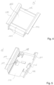
- the shape of the locking hooks 102, 104 is shown in the sectional views along the lines HH and JJ in the views at the top and bottom right and in Fig. 5 which shows the underside of the adapter 10 ⁇ in a perspective view.
- the locking hooks 102, 104 are designed to fit into corresponding openings 102', 104' ( Fig. 1 ) on the front panel 14 ⁇ ( Fig. 1 ) of a switching device 14 ( Fig. 1 ) and to engage in it by moving the adapter 10 ⁇ in the mounting plane in such a way that the adapter 10 ⁇ cannot fall off the switching device without moving.
- the snap hooks 106, 108 are designed in the form of tongues with projections at their free ends.
- the projections are designed to engage or snap into corresponding slot-shaped snap openings 106', 108 ⁇ ( Fig. 1 ) on the front panel 14 ⁇ ( Fig. 1 ) of a switching device 14 ( Fig. 1 ).
- the snap hooks 106, 108 are arranged and designed in such a way that the projections, after the snap hooks 102, 104 have snapped into place when the adapter 10' has been moved, are located approximately above the snap openings 106', 108' provided for them and can snap into them.
- the snap hooks 106, 108 Due to the tongue-shaped design of the snap hooks 106, 108, with the appropriate material selection they can act like springs which press the projections into the snap openings 106', 108', whereby slipping of the adapter 10' on the front panel in the assembled state, ie after everything has snapped into place, can be effectively prevented. Releasing the connection between adapter 10' and front panel then requires overcoming the spring forces of the snap hooks 106, 108 and moving the adapter 10' accordingly so that the snap-in hooks 102, 104 can be released from their locking position.
- Fig. 4 the adapter 10 ⁇ is shown in a perspective view from above.
- Two projections 114, 116 in the form of partitions can extend between the clamping legs 110, 112 arranged on the two long sides of the base plate 100.
- These projections 114, 116 can, for example, form a safeguard against slipping of a component mounted on the top of the adapter 10 ⁇ and/or serve as an assembly aid for aligning a component to be mounted. They can also improve the stability of the adapter 10 ⁇ because they form cross braces, which can prevent the adapter 10 ⁇ from twisting.
- the stabilization can reduce the material thickness of the base plate 100 under certain circumstances, which can save space in a stacked arrangement.
- the adapter 10, 10' can be made in one piece from a material which can in particular have sufficient strength and spring strength for the snap hooks.
- a particularly suitable material is plastic with sufficient spring stiffness.
- the adapter can also be designed as a stamped part, for example from spring steel.
Landscapes
- Engineering & Computer Science (AREA)
- Power Engineering (AREA)
- Microelectronics & Electronic Packaging (AREA)
- Mounting Components In General For Electric Apparatus (AREA)
- Casings For Electric Apparatus (AREA)
Claims (8)
- Adaptateur (10 ; 10') de montage de composants électrotechniques (12, 14) qui est réalisé sous la forme d'un rail DIN, en particulier d'un profilé chapeau, et qui présente, sur sa face supérieure, des moyens de fixation (110, 112) pour le montage d'un composant électrotechnique et, sur sa face inférieure, des moyens de fixation (102, 104, 106, 108) pour le montage sur la plaque frontale (12', 14') d'un composant électrotechnique (12, 14), les moyens de fixation présentant, sur la face inférieure de l'adaptateur, au moins un crochet d'encliquetage (102, 104) qui est conçu pour s'encliqueter dans une ouverture d'encliquetage correspondante (102', 104') sur la plaque frontale (14') du composant électrotechnique (14), caractérisé en ce que les moyens de fixation présentent, sur la face inférieure de l'adaptateur, au moins un crochet à déclic (106, 108), qui est conçu pour s'encliqueter dans une ouverture d'encliquetage correspondante (106', 108') sur la plaque frontale (14') du composant électrotechnique (14), les moyens de fixation étant adaptés à fixer l'adaptateur (10, 10') sur la plaque frontale (12', 14') du composant électrotechnique (12, 14) de façon que l'adaptateur (10, 10') ne puisse pas glisser sur la plaque frontale (14').
- Adaptateur selon la revendication 1, caractérisé en ce qu'au moins une saillie (114, 116) est disposée sur la face supérieure de l'adaptateur (10').
- Adaptateur selon l'une quelconque des revendications précédentes, caractérisé en ce que les moyens de fixation, sur la face inférieure de l'adaptateur, présentent au moins une vis qui peut être vissée dans une ouverture filetée correspondante sur la plaque frontale (12', 14') d'un composant électrotechnique (12, 14).
- Adaptateur selon l'une quelconque des revendications précédentes, caractérisé en ce que les moyens de fixation, sur la face supérieure de l'adaptateur, présentent au moins un filet dans lequel peut être vissée une vis disposée sur la face inférieure d'un composant électrotechnique (12, 14).
- Adaptateur selon l'une quelconque des revendications précédentes, caractérisé en ce qu'au moins l'un des moyens de fixation (102, 104, 106, 108) sur la face inférieure de l'adaptateur (10 ; 10') est conçu de manière à pouvoir coopérer avec une ouverture d'encliquetage (102', 104') qui sert au montage d'un composant supplémentaire sur la plaque frontale (12', 14') d'un composant électrotechnique (12, 14).
- Adaptateur selon l'une quelconque des revendications précédentes, caractérisé en ce qu'il est fabriqué en matière plastique.
- Adaptateur selon l'une quelconques des revendications précédentes, caractérisé en ce que ses dimensions dans le plan de montage sont adaptées à la plaque frontale (12', 14') d'au moins un composant électrotechnique (12, 14), de façon qu'aucune partie de l'adaptateur ne dépasse de la ou des plaques frontales.
- Ensemble empilé de deux composants électrotechniques (12, 14), dans lequel un adaptateur (10) selon l'une des revendications 1 à 7, est monté sur la plaque frontale d'un premier composant (12) de l'ensemble et un second composant (14) comprenant des moyens de fixation sur sa face inférieure est monté sur les moyens de fixation sur la face supérieure de l'adaptateur (10).
Applications Claiming Priority (2)
| Application Number | Priority Date | Filing Date | Title |
|---|---|---|---|
| DE102017129217.9A DE102017129217A1 (de) | 2017-12-08 | 2017-12-08 | Adapter zur Montage elektrotechnischer Bauteile |
| PCT/EP2018/082988 WO2019110414A1 (fr) | 2017-12-08 | 2018-11-29 | Adaptateur pour le montage de composants électrotechniques |
Publications (2)
| Publication Number | Publication Date |
|---|---|
| EP3721514A1 EP3721514A1 (fr) | 2020-10-14 |
| EP3721514B1 true EP3721514B1 (fr) | 2024-11-27 |
Family
ID=64559706
Family Applications (1)
| Application Number | Title | Priority Date | Filing Date |
|---|---|---|---|
| EP18811534.9A Active EP3721514B1 (fr) | 2017-12-08 | 2018-11-29 | Adaptateur de montage de composants électrotechniques |
Country Status (5)
| Country | Link |
|---|---|
| US (1) | US11140795B2 (fr) |
| EP (1) | EP3721514B1 (fr) |
| CN (1) | CN111684675B (fr) |
| DE (1) | DE102017129217A1 (fr) |
| WO (1) | WO2019110414A1 (fr) |
Families Citing this family (4)
| Publication number | Priority date | Publication date | Assignee | Title |
|---|---|---|---|---|
| BE1028671B1 (de) | 2020-10-05 | 2022-05-03 | Phoenix Contact Gmbh & Co | Montageanordnung zur Montage von zumindest zwei etagenweise übereinander anordenbaren elektrischen Modulen und eine Geräteanordnung |
| DE102020126019A1 (de) | 2020-10-05 | 2022-04-07 | Phoenix Contact Gmbh & Co. Kg | Montageanordnung zur Montage von zumindest zwei etagenweise übereinander anordenbaren elektrischen Modulen und eine Geräteanordnung |
| US11576275B2 (en) * | 2021-02-26 | 2023-02-07 | Adlink Technology Inc. | DIN rail installation kit and its operation method |
| US20250372316A1 (en) * | 2024-05-29 | 2025-12-04 | Arushi Singh | Method for forming a supercapacitor |
Citations (5)
| Publication number | Priority date | Publication date | Assignee | Title |
|---|---|---|---|---|
| EP0762581A1 (fr) * | 1995-09-04 | 1997-03-12 | Sprecher + Schuh Ag | Dispositif pour fixer un appareil électrique sur un adaptateur |
| DE19836762A1 (de) * | 1998-08-13 | 2000-02-17 | Woehner Gmbh & Co Kg | Sammelschienen-Adapter |
| DE102005009993B3 (de) * | 2005-03-04 | 2006-06-14 | Rittal Gmbh & Co. Kg | Geräteadapter |
| DE102012016094B4 (de) * | 2012-08-14 | 2016-09-22 | Phoenix Contact Gmbh & Co. Kg | Montageadaptereinrichtung |
| DE202016103379U1 (de) * | 2016-06-27 | 2017-09-29 | Wago Verwaltungsgesellschaft Mbh | Tragschienenadapter |
Family Cites Families (16)
| Publication number | Priority date | Publication date | Assignee | Title |
|---|---|---|---|---|
| FR2447132A1 (fr) | 1979-01-18 | 1980-08-14 | Telemecanique Electrique | Dispositif de support pour appareils electriques |
| DE4127253A1 (de) * | 1991-08-17 | 1993-02-18 | Abb Patent Gmbh | Zur wand- oder bodenbefestigung geeignetes gehaeuse |
| DE29508611U1 (de) * | 1995-05-24 | 1995-08-03 | Klöckner-Moeller GmbH, 53115 Bonn | Universal-Motorschutzrelais und Anordnungen hierzu |
| DE29518349U1 (de) | 1995-11-18 | 1997-03-27 | Moeller GmbH, 53115 Bonn | Verstärkerbaustein für mit rückseitigen Mitteln zur Tragschienenbefestigung versehene Schütze |
| DE19748531A1 (de) | 1997-11-03 | 1999-05-06 | Siemens Ag | Aufbausystem für Verbraucherabzweige mit stehender Verdrahtung |
| DE19809293C1 (de) | 1998-03-05 | 1999-09-30 | Moeller Gmbh | Schutzeinrichtung für ein Elektroenergiesystem |
| US6531940B1 (en) | 1999-08-12 | 2003-03-11 | Siemens Aktiengesellschaft | Combined contactor/soft starter |
| US7073971B2 (en) * | 2004-02-10 | 2006-07-11 | Egs Electrical Group, Llc | Apparatus and methods for detachably mounting devices to rails |
| DE202008015309U1 (de) | 2008-02-02 | 2009-08-13 | Weidmüller Interface GmbH & Co. KG | Montagesystem für elektrische und/oder mechanische Komponenten |
| EP2086077A3 (fr) * | 2008-02-02 | 2013-07-24 | Weidmüller Interface GmbH & Co. KG | Système de montage pour composants électriques et/ou mécaniques |
| CN201708101U (zh) * | 2010-05-21 | 2011-01-12 | 薛文锋 | 用于导轨与断路器连接的卡扣 |
| DE102012014980A1 (de) * | 2012-07-25 | 2014-05-15 | Friedrich Lütze GmbH | Montagesystem für die Anordnung von beispielsweise elektrischen Einrichtungen insbesondere in Schaltschränken |
| CN202817505U (zh) * | 2012-09-27 | 2013-03-20 | 德力西电气有限公司 | 一种小型低压开关底座安装结构 |
| US20140357095A1 (en) * | 2013-06-03 | 2014-12-04 | Toyota Motor Engineering & Manufacturing North America, Inc. | Block connector holder |
| DE202014101491U1 (de) | 2014-03-28 | 2015-07-06 | Weidmüller Interface GmbH & Co. KG | Busfähiges aneinanderreihbares Anschluss- und/oder Funktionsmodul |
| CN204046995U (zh) * | 2014-09-09 | 2014-12-24 | 泰科电子(上海)有限公司 | 固定支架和控制设备 |
-
2017
- 2017-12-08 DE DE102017129217.9A patent/DE102017129217A1/de not_active Withdrawn
-
2018
- 2018-11-29 CN CN201880087361.0A patent/CN111684675B/zh active Active
- 2018-11-29 WO PCT/EP2018/082988 patent/WO2019110414A1/fr not_active Ceased
- 2018-11-29 US US16/770,088 patent/US11140795B2/en active Active
- 2018-11-29 EP EP18811534.9A patent/EP3721514B1/fr active Active
Patent Citations (5)
| Publication number | Priority date | Publication date | Assignee | Title |
|---|---|---|---|---|
| EP0762581A1 (fr) * | 1995-09-04 | 1997-03-12 | Sprecher + Schuh Ag | Dispositif pour fixer un appareil électrique sur un adaptateur |
| DE19836762A1 (de) * | 1998-08-13 | 2000-02-17 | Woehner Gmbh & Co Kg | Sammelschienen-Adapter |
| DE102005009993B3 (de) * | 2005-03-04 | 2006-06-14 | Rittal Gmbh & Co. Kg | Geräteadapter |
| DE102012016094B4 (de) * | 2012-08-14 | 2016-09-22 | Phoenix Contact Gmbh & Co. Kg | Montageadaptereinrichtung |
| DE202016103379U1 (de) * | 2016-06-27 | 2017-09-29 | Wago Verwaltungsgesellschaft Mbh | Tragschienenadapter |
Also Published As
| Publication number | Publication date |
|---|---|
| US20210014993A1 (en) | 2021-01-14 |
| WO2019110414A1 (fr) | 2019-06-13 |
| CN111684675A (zh) | 2020-09-18 |
| DE102017129217A1 (de) | 2019-06-13 |
| EP3721514A1 (fr) | 2020-10-14 |
| US11140795B2 (en) | 2021-10-05 |
| CN111684675B (zh) | 2022-07-01 |
Similar Documents
| Publication | Publication Date | Title |
|---|---|---|
| DE3903752C2 (fr) | ||
| EP3721514B1 (fr) | Adaptateur de montage de composants électrotechniques | |
| EP3639334B1 (fr) | Fixation a un rail de support | |
| DE202013104785U1 (de) | Reihenbausteinanordnung mit einem Energiebussystem | |
| DE68903836T2 (de) | Verbrauchereinheiten. | |
| EP1701369B1 (fr) | Disjoncteur électromécanique | |
| DE102012102170A1 (de) | Montageeinheit und verfahren zur montage einer montageschiene an einer montageplatte für einen schaltschrank | |
| EP2237383A2 (fr) | Armoire avec barres omnibus enfichables | |
| DE2616525C2 (de) | Elektrische Installationsverteilung | |
| EP1254495B1 (fr) | Disposition de fixation d'appareillages de commutation sur des profils supports | |
| EP2429037B1 (fr) | Elément de serrage de cadre pour commutateurs électromécaniques doté d'une pièce de raccordement intégrée | |
| DE102013110788B4 (de) | Sammelschienen-Adapter | |
| WO2007068351A1 (fr) | Appareillage d’installation électrique | |
| EP4107767B1 (fr) | Dispositif de protection contre les surtensions, ensembles de protection contre les surtensions comportant un tel dispositif de protection contre les surtensions et procédé d'assemblage d'un ensemble de protection contre les surtensions | |
| DE102018131963A1 (de) | Vorrichtung zur elektrischen Verbindung eines ersten und zweiten Sammelschienensystems in einem elektrischen Verteiler, sowie elektrischer Verteiler enthaltend eine solche Vorrichtung | |
| EP2339710B1 (fr) | Appareil d'installation électrique | |
| DE9403259U1 (de) | Gehäuseaufbau für einen Niederspannungs-Schutzschalter mit Hilfsschalterblock | |
| DE202016103379U1 (de) | Tragschienenadapter | |
| DE102016111847A1 (de) | Durchführungsklemme | |
| DE3037405A1 (de) | Elektrisches niederspannungsschaltegeraet | |
| DE10260371B4 (de) | Niederspannungs-Leistungsschalter | |
| DE102006053415B3 (de) | Befestigungsvorrichtung | |
| EP3993189A1 (fr) | Dispositif de fixation pour un module sur un rail de support | |
| EP1376793B1 (fr) | Adaptateur pour l'installation de blocs de connection dans des dispositifs de distribution électrique | |
| DE202021001123U1 (de) | Zählersteckklemme zm Anschließen von elektrischen Leitungen an einem Stromzähler mit Dreipunktbefestigung |
Legal Events
| Date | Code | Title | Description |
|---|---|---|---|
| STAA | Information on the status of an ep patent application or granted ep patent |
Free format text: STATUS: UNKNOWN |
|
| STAA | Information on the status of an ep patent application or granted ep patent |
Free format text: STATUS: THE INTERNATIONAL PUBLICATION HAS BEEN MADE |
|
| PUAI | Public reference made under article 153(3) epc to a published international application that has entered the european phase |
Free format text: ORIGINAL CODE: 0009012 |
|
| STAA | Information on the status of an ep patent application or granted ep patent |
Free format text: STATUS: REQUEST FOR EXAMINATION WAS MADE |
|
| 17P | Request for examination filed |
Effective date: 20200605 |
|
| AK | Designated contracting states |
Kind code of ref document: A1 Designated state(s): AL AT BE BG CH CY CZ DE DK EE ES FI FR GB GR HR HU IE IS IT LI LT LU LV MC MK MT NL NO PL PT RO RS SE SI SK SM TR |
|
| AX | Request for extension of the european patent |
Extension state: BA ME |
|
| DAV | Request for validation of the european patent (deleted) | ||
| DAX | Request for extension of the european patent (deleted) | ||
| STAA | Information on the status of an ep patent application or granted ep patent |
Free format text: STATUS: EXAMINATION IS IN PROGRESS |
|
| 17Q | First examination report despatched |
Effective date: 20220221 |
|
| P01 | Opt-out of the competence of the unified patent court (upc) registered |
Effective date: 20230521 |
|
| GRAP | Despatch of communication of intention to grant a patent |
Free format text: ORIGINAL CODE: EPIDOSNIGR1 |
|
| STAA | Information on the status of an ep patent application or granted ep patent |
Free format text: STATUS: GRANT OF PATENT IS INTENDED |
|
| RIC1 | Information provided on ipc code assigned before grant |
Ipc: H02B 1/32 20060101ALN20240725BHEP Ipc: H02B 1/04 20060101ALN20240725BHEP Ipc: H01H 71/02 20060101ALI20240725BHEP Ipc: H02B 1/052 20060101AFI20240725BHEP |
|
| INTG | Intention to grant announced |
Effective date: 20240805 |
|
| GRAS | Grant fee paid |
Free format text: ORIGINAL CODE: EPIDOSNIGR3 |
|
| GRAA | (expected) grant |
Free format text: ORIGINAL CODE: 0009210 |
|
| STAA | Information on the status of an ep patent application or granted ep patent |
Free format text: STATUS: THE PATENT HAS BEEN GRANTED |
|
| AK | Designated contracting states |
Kind code of ref document: B1 Designated state(s): AL AT BE BG CH CY CZ DE DK EE ES FI FR GB GR HR HU IE IS IT LI LT LU LV MC MK MT NL NO PL PT RO RS SE SI SK SM TR |
|
| REG | Reference to a national code |
Ref country code: GB Ref legal event code: FG4D Free format text: NOT ENGLISH |
|
| REG | Reference to a national code |
Ref country code: CH Ref legal event code: EP |
|
| REG | Reference to a national code |
Ref country code: DE Ref legal event code: R096 Ref document number: 502018015371 Country of ref document: DE |
|
| REG | Reference to a national code |
Ref country code: IE Ref legal event code: FG4D Free format text: LANGUAGE OF EP DOCUMENT: GERMAN |
|
| REG | Reference to a national code |
Ref country code: LT Ref legal event code: MG9D |
|
| REG | Reference to a national code |
Ref country code: NL Ref legal event code: MP Effective date: 20241127 |
|
| PG25 | Lapsed in a contracting state [announced via postgrant information from national office to epo] |
Ref country code: IS Free format text: LAPSE BECAUSE OF FAILURE TO SUBMIT A TRANSLATION OF THE DESCRIPTION OR TO PAY THE FEE WITHIN THE PRESCRIBED TIME-LIMIT Effective date: 20250327 Ref country code: HR Free format text: LAPSE BECAUSE OF FAILURE TO SUBMIT A TRANSLATION OF THE DESCRIPTION OR TO PAY THE FEE WITHIN THE PRESCRIBED TIME-LIMIT Effective date: 20241127 Ref country code: PT Free format text: LAPSE BECAUSE OF FAILURE TO SUBMIT A TRANSLATION OF THE DESCRIPTION OR TO PAY THE FEE WITHIN THE PRESCRIBED TIME-LIMIT Effective date: 20250327 |
|
| PG25 | Lapsed in a contracting state [announced via postgrant information from national office to epo] |
Ref country code: NL Free format text: LAPSE BECAUSE OF FAILURE TO SUBMIT A TRANSLATION OF THE DESCRIPTION OR TO PAY THE FEE WITHIN THE PRESCRIBED TIME-LIMIT Effective date: 20241127 Ref country code: FI Free format text: LAPSE BECAUSE OF FAILURE TO SUBMIT A TRANSLATION OF THE DESCRIPTION OR TO PAY THE FEE WITHIN THE PRESCRIBED TIME-LIMIT Effective date: 20241127 |
|
| PG25 | Lapsed in a contracting state [announced via postgrant information from national office to epo] |
Ref country code: BG Free format text: LAPSE BECAUSE OF FAILURE TO SUBMIT A TRANSLATION OF THE DESCRIPTION OR TO PAY THE FEE WITHIN THE PRESCRIBED TIME-LIMIT Effective date: 20241127 |
|
| PG25 | Lapsed in a contracting state [announced via postgrant information from national office to epo] |
Ref country code: ES Free format text: LAPSE BECAUSE OF FAILURE TO SUBMIT A TRANSLATION OF THE DESCRIPTION OR TO PAY THE FEE WITHIN THE PRESCRIBED TIME-LIMIT Effective date: 20241127 |
|
| PG25 | Lapsed in a contracting state [announced via postgrant information from national office to epo] |
Ref country code: NO Free format text: LAPSE BECAUSE OF FAILURE TO SUBMIT A TRANSLATION OF THE DESCRIPTION OR TO PAY THE FEE WITHIN THE PRESCRIBED TIME-LIMIT Effective date: 20250227 |
|
| PG25 | Lapsed in a contracting state [announced via postgrant information from national office to epo] |
Ref country code: GR Free format text: LAPSE BECAUSE OF FAILURE TO SUBMIT A TRANSLATION OF THE DESCRIPTION OR TO PAY THE FEE WITHIN THE PRESCRIBED TIME-LIMIT Effective date: 20250228 Ref country code: LV Free format text: LAPSE BECAUSE OF FAILURE TO SUBMIT A TRANSLATION OF THE DESCRIPTION OR TO PAY THE FEE WITHIN THE PRESCRIBED TIME-LIMIT Effective date: 20241127 |
|
| PG25 | Lapsed in a contracting state [announced via postgrant information from national office to epo] |
Ref country code: PL Free format text: LAPSE BECAUSE OF FAILURE TO SUBMIT A TRANSLATION OF THE DESCRIPTION OR TO PAY THE FEE WITHIN THE PRESCRIBED TIME-LIMIT Effective date: 20241127 |
|
| PG25 | Lapsed in a contracting state [announced via postgrant information from national office to epo] |
Ref country code: RS Free format text: LAPSE BECAUSE OF FAILURE TO SUBMIT A TRANSLATION OF THE DESCRIPTION OR TO PAY THE FEE WITHIN THE PRESCRIBED TIME-LIMIT Effective date: 20250227 |
|
| REG | Reference to a national code |
Ref country code: CH Ref legal event code: PL |
|
| PG25 | Lapsed in a contracting state [announced via postgrant information from national office to epo] |
Ref country code: SM Free format text: LAPSE BECAUSE OF FAILURE TO SUBMIT A TRANSLATION OF THE DESCRIPTION OR TO PAY THE FEE WITHIN THE PRESCRIBED TIME-LIMIT Effective date: 20241127 |
|
| PG25 | Lapsed in a contracting state [announced via postgrant information from national office to epo] |
Ref country code: DK Free format text: LAPSE BECAUSE OF FAILURE TO SUBMIT A TRANSLATION OF THE DESCRIPTION OR TO PAY THE FEE WITHIN THE PRESCRIBED TIME-LIMIT Effective date: 20241127 |
|
| PG25 | Lapsed in a contracting state [announced via postgrant information from national office to epo] |
Ref country code: LU Free format text: LAPSE BECAUSE OF NON-PAYMENT OF DUE FEES Effective date: 20241129 |
|
| REG | Reference to a national code |
Ref country code: CH Ref legal event code: PL |
|
| PG25 | Lapsed in a contracting state [announced via postgrant information from national office to epo] |
Ref country code: EE Free format text: LAPSE BECAUSE OF FAILURE TO SUBMIT A TRANSLATION OF THE DESCRIPTION OR TO PAY THE FEE WITHIN THE PRESCRIBED TIME-LIMIT Effective date: 20241127 |
|
| PG25 | Lapsed in a contracting state [announced via postgrant information from national office to epo] |
Ref country code: CH Free format text: LAPSE BECAUSE OF NON-PAYMENT OF DUE FEES Effective date: 20241130 |
|
| PG25 | Lapsed in a contracting state [announced via postgrant information from national office to epo] |
Ref country code: RO Free format text: LAPSE BECAUSE OF FAILURE TO SUBMIT A TRANSLATION OF THE DESCRIPTION OR TO PAY THE FEE WITHIN THE PRESCRIBED TIME-LIMIT Effective date: 20241127 |
|
| PG25 | Lapsed in a contracting state [announced via postgrant information from national office to epo] |
Ref country code: SK Free format text: LAPSE BECAUSE OF FAILURE TO SUBMIT A TRANSLATION OF THE DESCRIPTION OR TO PAY THE FEE WITHIN THE PRESCRIBED TIME-LIMIT Effective date: 20241127 |
|
| PG25 | Lapsed in a contracting state [announced via postgrant information from national office to epo] |
Ref country code: CZ Free format text: LAPSE BECAUSE OF FAILURE TO SUBMIT A TRANSLATION OF THE DESCRIPTION OR TO PAY THE FEE WITHIN THE PRESCRIBED TIME-LIMIT Effective date: 20241127 |
|
| PG25 | Lapsed in a contracting state [announced via postgrant information from national office to epo] |
Ref country code: IT Free format text: LAPSE BECAUSE OF FAILURE TO SUBMIT A TRANSLATION OF THE DESCRIPTION OR TO PAY THE FEE WITHIN THE PRESCRIBED TIME-LIMIT Effective date: 20241127 |
|
| REG | Reference to a national code |
Ref country code: BE Ref legal event code: MM Effective date: 20241130 Ref country code: DE Ref legal event code: R097 Ref document number: 502018015371 Country of ref document: DE |
|
| PG25 | Lapsed in a contracting state [announced via postgrant information from national office to epo] |
Ref country code: SE Free format text: LAPSE BECAUSE OF FAILURE TO SUBMIT A TRANSLATION OF THE DESCRIPTION OR TO PAY THE FEE WITHIN THE PRESCRIBED TIME-LIMIT Effective date: 20241127 |
|
| PG25 | Lapsed in a contracting state [announced via postgrant information from national office to epo] |
Ref country code: MC Free format text: LAPSE BECAUSE OF FAILURE TO SUBMIT A TRANSLATION OF THE DESCRIPTION OR TO PAY THE FEE WITHIN THE PRESCRIBED TIME-LIMIT Effective date: 20241127 |
|
| PLBE | No opposition filed within time limit |
Free format text: ORIGINAL CODE: 0009261 |
|
| STAA | Information on the status of an ep patent application or granted ep patent |
Free format text: STATUS: NO OPPOSITION FILED WITHIN TIME LIMIT |
|
| PG25 | Lapsed in a contracting state [announced via postgrant information from national office to epo] |
Ref country code: BE Free format text: LAPSE BECAUSE OF NON-PAYMENT OF DUE FEES Effective date: 20241130 |
|
| PG25 | Lapsed in a contracting state [announced via postgrant information from national office to epo] |
Ref country code: IE Free format text: LAPSE BECAUSE OF NON-PAYMENT OF DUE FEES Effective date: 20241129 |
|
| 26N | No opposition filed |
Effective date: 20250828 |
|
| PGFP | Annual fee paid to national office [announced via postgrant information from national office to epo] |
Ref country code: DE Payment date: 20251022 Year of fee payment: 8 |
|
| PGFP | Annual fee paid to national office [announced via postgrant information from national office to epo] |
Ref country code: GB Payment date: 20251023 Year of fee payment: 8 |
|
| PG25 | Lapsed in a contracting state [announced via postgrant information from national office to epo] |
Ref country code: AT Free format text: LAPSE BECAUSE OF NON-PAYMENT OF DUE FEES Effective date: 20241129 |
|
| PGFP | Annual fee paid to national office [announced via postgrant information from national office to epo] |
Ref country code: FR Payment date: 20251022 Year of fee payment: 8 |
|
| REG | Reference to a national code |
Ref country code: AT Ref legal event code: MM01 Ref document number: 1746660 Country of ref document: AT Kind code of ref document: T Effective date: 20241129 |
|
| PG25 | Lapsed in a contracting state [announced via postgrant information from national office to epo] |
Ref country code: HU Free format text: LAPSE BECAUSE OF FAILURE TO SUBMIT A TRANSLATION OF THE DESCRIPTION OR TO PAY THE FEE WITHIN THE PRESCRIBED TIME-LIMIT; INVALID AB INITIO Effective date: 20181129 |
|
| PG25 | Lapsed in a contracting state [announced via postgrant information from national office to epo] |
Ref country code: CY Free format text: LAPSE BECAUSE OF FAILURE TO SUBMIT A TRANSLATION OF THE DESCRIPTION OR TO PAY THE FEE WITHIN THE PRESCRIBED TIME-LIMIT; INVALID AB INITIO Effective date: 20181129 |