EP3721741A1 - Système d'alarme pour joggeurs - Google Patents
Système d'alarme pour joggeurs Download PDFInfo
- Publication number
- EP3721741A1 EP3721741A1 EP20168315.8A EP20168315A EP3721741A1 EP 3721741 A1 EP3721741 A1 EP 3721741A1 EP 20168315 A EP20168315 A EP 20168315A EP 3721741 A1 EP3721741 A1 EP 3721741A1
- Authority
- EP
- European Patent Office
- Prior art keywords
- alarm
- trigger
- alarm system
- hand
- designed
- Prior art date
- Legal status (The legal status is an assumption and is not a legal conclusion. Google has not performed a legal analysis and makes no representation as to the accuracy of the status listed.)
- Granted
Links
Images



Classifications
-
- G—PHYSICS
- G08—SIGNALLING
- G08B—SIGNALLING SYSTEMS, e.g. PERSONAL CALLING SYSTEMS; ORDER TELEGRAPHS; ALARM SYSTEMS
- G08B25/00—Alarm systems in which the location of the alarm condition is signalled to a central station, e.g. fire or police telegraphic systems
- G08B25/01—Alarm systems in which the location of the alarm condition is signalled to a central station, e.g. fire or police telegraphic systems characterised by the transmission medium
- G08B25/016—Personal emergency signalling and security systems
-
- G—PHYSICS
- G08—SIGNALLING
- G08B—SIGNALLING SYSTEMS, e.g. PERSONAL CALLING SYSTEMS; ORDER TELEGRAPHS; ALARM SYSTEMS
- G08B15/00—Identifying, scaring or incapacitating burglars, thieves or intruders, e.g. by explosives
- G08B15/004—Identifying, scaring or incapacitating burglars, thieves or intruders, e.g. by explosives using portable personal devices
Definitions
- the WO 2008/113846 A1 describes a handheld device with a receiver and a system for personal security. When an alarm is activated on the handset, a flash of light can be emitted, a siren sounded or pepper gas can be sprayed.
- the device also has a video camera, a GPS receiver, a microphone and an LCD display. When activated, a video and sound recording is started.
- the device can be attached to the hand using loops.
- the housing is made of plastic and can break if dropped. Due to the multitude of functions, the expected dimensions and the expected weight, the device is unsuitable for sporting activities and especially when jogging.
- the fastening by means of loops in particular proves to be disadvantageous with regard to the fixing of the position of the hand-held device on the user.
- the hand-held device does not lie firmly on the user's hand or is held there. As a result, relative movements in relation to the user's hand are promoted, which can lead to minor but nevertheless annoying and permanent blows to the hand. This can lead to skin irritation and even to local abrasion of the skin and thus to injuries.
- Security devices which can be worn on the person and which can emit a very loud alarm tone have also become known.
- a safety device can be worn around the wrist similar to a bracelet or a wristwatch.
- the safety device is linked to a smartphone via a program. If the alarm is triggered, an alarm tone sounds, a beacon is sent out and stored contacts can be sent via Email and SMS will be informed.
- the current position can be determined using GPS and sent to a stored contact via SMS. In any case, two hands are required to trigger an alarm, so that actuation may no longer be possible in the event of an unexpected attack from behind. Therefore, such a safety device does not meet the safety needs of women, for example, when jogging.
- Personal locating devices have also become known which have their own SIM card, a GSM receiver and a GPS positioning system.
- the person tracking device is worn on a loop around the neck. If the SOS button is pressed for a few seconds, an emergency call is made. In particular, the device is activated in the event of a fall or severe vibration. This has the disadvantage that unintentional triggering is possible even while jogging. Therefore the person tracking device is unsuitable for joggers.
- a personal protection device which includes a stun gun and a gas spray device.
- the alarm system can be activated by pressing a button or voice command.
- the device must be held in hand at all times. Due to the large number of functions and the resulting dimensions, the device is quite large and unsuitable for being constantly held in hand while jogging. But if you put it in a pocket of a jacket or something similar. stored, it is not directly available in the event of an unexpected attack. Therefore the device is unsuitable for joggers.
- the US 2015/0109123 A1 discloses a personal security apparatus that is embedded in a jewelry element such as an amulet or a wrist watch.
- the device is activated by pressing a switch.
- the security device can be linked to a smartphone which, when activated, makes contact with previously stored emergency contacts.
- jogging jewelry items are generally a hindrance.
- Decorative items are particularly annoying during sporting activities and especially when jogging, as they can sometimes hang down and swing on the body.
- the alarm cannot be triggered directly in the event of an unexpected attack. They also pose an additional risk of injury, for example if they fall or if they get caught in another object.
- Decorative items can also lead to skin irritation during endurance sports and even to skin abrasions if they are constantly moved relative to one another.
- the alarm device has at least one data interface with at least one sending and / or receiving unit for sending and / or receiving data, the data interface being designed and set up to have a (particularly permanent) radio connection with at least one mobile radio unit such as a local one during normal operation To hold mobile radio device or a remote mobile radio base or mobile radio station, wherein the carrying device is provided and designed to be captured on a body of a user in a captive manner.
- the alarm device comprises a housing and at least one trigger for actuation as required in the event of an alarm.
- the housing has a top and a bottom (and side surfaces).
- the trigger is located on the top of the housing.
- the carrying device is provided and designed to be received on a body and in particular on a hand of the user in a captive manner and in particular in a form-fitting manner.
- the carrying device is designed such that, when used as intended, it at least partially encloses the palm of the hand and also the back of the hand of the metacarpal of a user.
- a glove for example, completely encloses the metacarpal of a user and over at least part of the length of the metacarpal. Accordingly, the carrying device can be designed like a glove and preferably only enclose the metacarpal over part of the length of the metacarpal.
- the underside of the housing rests directly or adjacent to the user's palm, for example via some fabric or the like, so that the trigger located on the top of the housing is completely unencumbered and freely accessible when the hand is open and in the event of imminent danger one-handed by closing the hand or by z.
- the pressure of a curved finger can be actuated to trigger the alarm.
- the Carrying device encloses the metacarpal over the entire circumference.
- the trigger and in particular the alarm device are arranged on and in particular within the palm of the hand of the user so that the trigger can be actuated with one hand by pressing a curved or curving finger or by closing the hand in the event of imminent danger.
- the trigger can in particular be actuated indirectly and / or directly, for example with a finger or the thumb of the hand.
- the alarm system is securely arranged on the user's hand. This means that the alarm system does not have to be kept active by the user himself. (At least individual) shaped elements of the carrying device are preferably adapted in a form-fitting manner to the shape of the metacarpal or hand, so that a particularly good hold is achieved. In particular, the alarm system therefore does not interfere with outdoor activities and especially not when jogging. A user is not restricted in his freedom of movement and can devote himself to his sporting activity with full concentration undisturbed. There are thus great advantages over the entire prior art.
- An alarm is preferably triggered by actuating the trigger.
- An alarm event in the context of the present invention is understood to mean an alarm.
- the term “alarm case” can be consistently replaced by the term “alarm”.
- the carrying device When worn as intended, the carrying device preferably surrounds at least two metacarpal bones of a hand of a user or a jogger on both sides of the palm and the back of the hand, at least in sections and / or in part.
- the alarm system can have additional devices such as a hair tie device or a head lamp device or another additional device. In the event of an alarm, these can take on additional functions that are detailed elsewhere.
- the support device of the alarm system preferably comprises at least partially a flexible material.
- the carrying device can comprise fabrics, leather, elastic plastic fibers or also naturally occurring materials. The list is not exhaustive. As a result, the carrying device can preferably adapt to the contour of the user's hand. Reflectors are preferably arranged on the carrying device and / or the carrying device can itself have striking colors and in particular preferably reflectors. This supports visual identification of the jogger. This is not only beneficial at dusk or in complete darkness. In particular, such a material is used which is compatible with the human body and the skin. It could also be designed as inconspicuously as possible.
- the support device comprises at least one closing element.
- the closing element is designed and / or at least comprises a Velcro fastener, a snap fastener or in the form of a button with a buttonhole and / or a buckle and / or a loop and / or a loop such an element. It is also conceivable to design the closing element as a click lock or as a hook connection.
- the closing element can also have or comprise at least one buckle, a loop and / or a quick release.
- a support device designed as a flexible band can be threaded into a buckle. A quick change of the length for tensioning and / or removal is possible.
- the band device may comprise a fabric and / or an elastic fabric band. If the band device comprises a fabric, the fabric preferably lies seamlessly against the skin of the user. This means that preferably no seam comes into direct contact with the skin of a user. This is advantageous because z. B. in a marathon, even the seams of clothing can lead to minor skin injuries or abrasions. This is reliably avoided if there is no seam on the skin.
- the belt device is essentially or completely formed from a textile fabric.
- the textile fabric or textile fabric can be tubular.
- the textile fabric is particularly advantageously elastic, so that a particularly good hold on the metacarpal is achieved.
- the textile fabric can in particular be connected to the alarm device via a closing element or can accommodate the alarm device inside or be arranged on it.
- the fabric can consist of one or more materials or also comprise several materials.
- the bracket device contains at least one U-shaped and / or V-shaped and / or one O-shaped bracket.
- the bracket partially encloses the middle hand of the user at least on the inside or the outside of the middle hand.
- the secure hold on the user's hand is promoted by the bracket.
- the brackets can be made from a metallic material and / or a plastic and / or an elastic material. In particular, such materials are used that are compatible with the human body and skin.
- connection between the alarm device and the carrying device is designed in particular to be detachable. In this way, simple maintenance and cleaning of the alarm device is particularly advantageous.
- the alarm device can for example be sewn into the carrying device in preferred embodiments. This enables the alarm device to be held securely on the carrying device.
- the alarm device can also be glued to the support device. In this way, the alarm device can simply be removed from the carrying device for maintenance or replacement.
- the alarm device can also in particular be at least partially screwed, in particular riveted, to the support device. In these embodiments, a firm hold, in particular a hold that cannot be released without further ado, is achieved between the carrying device and the alarm device.
- a releasable connection is also created by a tab or buckle, through which a flexible fabric strap is passed through and tensioned as a carrying device, such as in a backpack.
- All electrical or electronic components are preferably contained or received in the housing of the alarm device and are protected against damage in the event of a fall or in the event of violence. This is particularly favorable for printed circuit boards, circuit boards, processors and electrically conductive connections, in particular cables with thin cross-sections, which can be quickly damaged in a bending movement.
- all components can advantageously be contained in a common housing in a space-saving and secure manner.
- the housing can particularly preferably be received in the palm of the user's hand.
- the alarm device can in particular adapt very well to the shape of the palm.
- the trigger is connected to the alarm device via a short cable.
- the two-part design is particularly notable for its space-saving and variable arrangement.
- a distance between the alarm device and the trigger of preferably a maximum of 20 cm, in particular a maximum of 10 cm, is provided.
- the alarm device can advantageously be arranged on the carrying device in such a way that the trigger can only be actuated indirectly or indirectly. This can be done, for example, by exerting pressure on the housing.
- the alarm device can preferably also be actuated by pressing the housing against another object or another body part, such as one's own body or the body of an attacker or against an object.
- the housing comprises an at least partially elastic material and has rounded edges.
- the housing can be made at least partially from plastic and / or metal, in particular from a light metal such as aluminum or magnesium.
- the housing preferably has no sharp-edged element.
- the housing is designed and constructed in such a way that no sharp-edged parts are created if the housing breaks. Reliable protection against injuries is thereby achieved.
- the housing has a maximum diameter of less than 6 cm or 5 cm or 4 cm or 2.5 cm. Diameters less than 2 cm or less than 1.5 cm are possible. A maximum height of the housing is in particular less than 2 cm and preferably less than 1.5 cm and also less than 1.25 cm or less than 1 cm. A maximum height of the housing of 8 mm or less than 7 mm or 6 mm or 5 mm or even 4 mm is also possible.
- the trigger preferably extends over a substantial portion of the surface of the top of the housing. The area of the trigger is in particular greater than 1 and preferably greater than 1.5 or 2 square centimeters.
- the housing is advantageously modeled at least partially on the palm of a person or a user. In this way, a particularly good reception and, in particular, a good and, in particular, secure hold can be made possible without slipping in the palm of the hand.
- the trigger extends over a substantial part of at least one surface the top of the housing, in particular over at least 25% or 50% of the surface of the top of the housing and preferably over more than 75% of the surface of the top. This ensures particularly simple handling and actuation in the event of an alarm.
- actuation in the form of a dead man's switch is also conceivable, in which the trigger must be actuated at regular intervals in order not to trigger the alarm.
- the alarm device is preferably convex at least on the underside of the housing.
- the alarm device When used as intended, the alarm device preferably rests flat against the (convex) palm of the user, at least on the underside.
- a minimum radius of curvature on the underside of the alarm device towards the side and end surfaces is particularly preferably at least 5 mm and in particular at least 7 mm or also 10 mm.
- the minimum rounding radius of 5 mm ensures an adapted shape and ideal adaptation to the palm of a user. Sharp transitions or sharp edges are avoided. Even a stepped transition with many small steps (more than 5 or 10) can be viewed as a continuous transition with an average rounding radius.
- the trigger also has a convex and outwardly curved contour.
- the trigger can particularly advantageously be actuated by several or all fingers. A possible actuation of the trigger with the thumb is advantageous.
- the alarm device has at least one trigger, which is designed as a cable switch.
- the cable switch can be integrated into the alarm device or be present on it.
- the cable of the cable switch can be worn around a wrist of the user in particular as a hand strap.
- the hand strap, the carrying device and / or the alarm device are removed from the hand of the user, the cable pull switch is preferably actuated. In this way, an alarm can be triggered even if the user does not actively press the trigger himself.
- the alarm system preferably comprises at least one control unit which is provided and designed to control the alarm.
- the control unit can be designed as a microcontroller with control software or hardwired be.
- the control unit can also include a program and / or an app which can be installed on an external device, such as a mobile radio device, and in particular a mobile phone or particularly preferably a smartphone or a smartwatch, and can also be executed from there.
- the control unit is advantageously provided and designed to coordinate, carry out and in particular carry out the individual functions of the alarm system by the control unit.
- the alarm system preferably comprises a mobile radio device as a mobile radio unit with at least one acoustic unit and / or at least one video unit, the mobile radio device being wirelessly coupled to the data interface of the alarm device via the radio link.
- the alarm when the trigger is actuated, the alarm is triggered (immediately) and at least one alarm signal is output to the mobile radio device.
- the mobile radio device is designed and set up to start a video recording and / or a sound recording on the mobile radio device after receiving an alarm signal via the data interface (preferably immediately and directly).
- the data interface of the alarm device can also be suitable for establishing a direct connection to a mobile radio unit or a remote mobile radio device.
- the data interface of the alarm device can also be suitable for connection to an additional device. This enables communication between the alarm device and the additional device and / or the mobile radio device, or a data connection is established.
- the data interface has at least one transmitting unit and at least one receiving unit and in particular at least one Sending and receiving unit for sending and / or receiving data.
- the data interface is therefore advantageously suitable for coupling the alarm device to the mobile radio device via control software, for example in the form of an app.
- control software for example in the form of an app.
- control software is advantageously included in the control unit and / or represents at least one component of the control unit.
- the mobile radio device is preferably designed and set up to establish the connection only after a waiting period.
- the waiting time can be set permanently, but can also be preset and changed.
- the alarm system, the alarm device and / or the mobile radio device or the control unit is designed and suitable for multiple and immediately successive actuation of the To recognize the trigger.
- a connection to a contact and / or the emergency call center is immediately established when the trigger is actuated multiple times.
- a multiple actuation of the trigger is understood to mean a multiple actuation in a short period of time, e.g. B. (more than) pressing the button three times within 3 or 5 seconds. Repeated actuation can be a sign that the user is at risk.
- control unit a multiple actuation (multiple actuation) of the release that takes place with a short time delay is recognized by the control unit.
- control unit it is also possible for the control unit to be suitable and designed to also detect a time length of the actuation of the trigger. In this way, for example, multiple triggering of an alarm can be prevented.
- a specific operating sequence e.g. long-short-long
- the alarm system is particularly preferably used only for alarm signals or for use in the event of an alarm.
- the alarm system is designed and set up to output a warning tone signal immediately after actuation of the trigger and to start data recording with audio and / or video data and to store it in an internal memory or external memory (local and / or remote).
- the recorded data are preferably also stored directly on cloud storage on the Internet.
- the alarm system is particularly preferably designed and set up to trigger an alarm if a data connection between the alarm device and the mobile radio unit or the (local) mobile radio device is lost.
- an alarm is triggered when the Movement speed of the user is recorded beyond physically possible values.
- an alarm is triggered immediately and a warning tone signal is output and data recording with audio and / or video data is started.
- the data are stored in an internal memory and / or external memory.
- the alarm system and in particular the alarm device can preferably comprise at least one acoustic unit.
- the acoustic unit is particularly set up and designed to record an ambient noise after the trigger has been actuated and to transmit it via the data interface.
- the alarm device preferably has at least one sound output unit and is set up and designed to output a warning sound signal in particular immediately and directly after the trigger has been actuated.
- existing video units and / or acoustic units from a coupled mobile radio device and / or an additional device can also be integrated into the alarm system and used in particular for the purposes of the alarm system. This makes it possible, in particular by actuating the shutter release, to control the acoustic unit and in particular the video unit and to initiate recordings.
- actuation of the trigger initiates an alarm and at least one alarm signal, which can be output and in particular forwarded in particular by the alarm device, particularly preferably by the mobile radio device.
- the alarm signal is output immediately after the alarm is actuated or triggered. It is possible for the alarm device and in particular the mobile radio device to return feedback to the user in the form of mechanical oscillation, in particular by vibration.
- the alarm device can comprise a separate vibration unit which generates vibrations that the user can feel.
- the audio signal can basically be output at any frequency. In this way, attackers can advantageously be driven to flight.
- the sound signal can be output by an acoustic unit in or on the alarm device or also by an acoustic unit on the mobile radio device.
- the audio signal is preferably emitted in at least one defined frequency spectrum. This means that the frequencies of the audio signal are precisely specified or result. In this way, the sound signal can advantageously be filtered out when a sound is recorded at the same time and it can e.g. an analysis or recognition of an attacker's voice can also be carried out afterwards.
- a sound signal is preferably used in at least one limited frequency band.
- a frequency band with a frequency width (half-width) less than 2000 Hz or less than 1500 Hz or less than 1000 Hz is preferred.
- the half-width is less than 800 Hz or less than 500 Hz.
- the half-width is preferably less than 25% and in particular less 15% or less than 10% of an average frequency of the respective frequency band.
- a sound signal with an average frequency of a frequency band of 5 kHz (or 4 or 6 kHz) and with a half width of less than 1000 Hz or 1500 Hz is used.
- a continuous audio signal is possible, but also a clocked one with a predetermined or adjustable frequency of e.g. 1 Hz or 2 Hz or 3 Hz.
- a clocked signal can attract even more attention.
- the output of the audio signal and a sound and / or video recording take place simultaneously.
- the audio signal can also be recorded. It is also possible that the audio signal is filtered out during the recording. Filtering out is also possible afterwards. For a transmission of the recorded sound, it is advantageous to at least largely filter out the sound signal in order to enable a distant listener to better understand the situation directly.
- the sound signal is preferably output by a piezo sound generator.
- the or at least one alarm signal is particularly preferably taken from a group of alarm signals which comprises radio signals, sound signals, light signals, video signals and audio signals.
- an audio signal in particular at least partially consisting of a sound signal such as a loud alarm tone and / or a siren tone, is initially output on the alarm device itself and / or on an additional device coupled or connected to it.
- video and audio signals can advantageously be recorded directly.
- the recording (audio and / or video recording) is preferably stored at least locally and / or transmitted as a radio signal to a mobile radio device and / or other additional devices connected via the data interface.
- the video recording and / or the sound recording is preferably initiated at least partially by a mobile radio device connected via the data interface, either directly or with a predefinable time delay after the trigger has been actuated by the control unit, or can be initiated via the data interface.
- a mobile radio device connected via the data interface
- the video unit and acoustic unit do not have to be integrated into the alarm device and the alarm device can be made smaller.
- error-prone electronic units do not have to be integrated into the alarm device.
- the immediate start of a recording after actuation makes it possible to record and save important details, for example of an attack, such as voices and / or appearance and / or background noises.
- a delayed start of a recording or its storage and transmission can also be useful.
- the sound recording and / or video recording is stored at least locally on the alarm system and preferably on the mobile radio device.
- a mobile radio device is designed in particular as a mobile phone and in particular as a smartphone or smartwatch or comprises at least one of these devices. The list is not exhaustive. Further other devices, radio devices or mobile radio devices can also be included.
- the control unit when the trigger is actuated, the establishment of a telephone connection with an emergency call center and / or previously stored and changeable contacts via the connected mobile radio device is initiated by the control unit.
- two, three or more changeable contacts can be stored in a ranking, which can be contacted one after the other and / or simultaneously. This ensures that the emergency contact or contacts who are in the immediate vicinity and / or can be reached at this moment are preferably alerted.
- an emergency contact Before jogging, an emergency contact can be selected before the sporting activity, which in the event of an acute alarm z. B. is in the vicinity and / or is available in time.
- at least one connection to a contact is preferably established.
- a contact comprises at least one telephone number and / or an email address and / or a messenger address and / or another protocol which are called or informed when the alarm is triggered.
- the notification of stored contacts can be initiated at least partially by at least one of the elements of the group, consisting of SMS, email and messenger message, via the activation of the alarm by a connected mobile radio device.
- notification of the stored emergency contacts can be ensured, even if they cannot accept the telephone connection at the moment and / or can only be reached by email and / or SMS and / or messenger.
- the notification of the stored contacts is preferably initiated immediately or particularly preferably with a time delay after actuation of the trigger.
- the jogger thus has sufficient time to deactivate the system in the event of unintentional triggering or the all-clear. However, this does not delete the alarm. If the emergency contacts are notified immediately after the trigger has been actuated, security is particularly high.
- the current GPS position data which can be determined in particular by a mobile radio device or additional device with a GPS receiver, are z. B. can be transmitted via SMS and / or email or another protocol. It is particularly advantageous here that the current GPS position data are transmitted or can be transmitted by radio signal.
- GPS data For the purposes of the present application, for the sake of simplicity, all satellite position data such as data about the GPS system or Galileo system or the Glonass system or also the Beidou system etc. are referred to as GPS data.
- the recordings can at least partially be transmitted and stored via a data connection, in particular via a coupled mobile radio device, to an in particular external database.
- the recordings or recordings can also be stored in at least one cloud storage device.
- the process is advantageously triggered and controlled by the control unit.
- the video recording of a video unit and a sound recording of an acoustic unit can be saved.
- At least some of the data of the video recording and the sound recording can also be stored locally on the mobile radio device or on another local device. This is particularly advantageous because it decouples the storage of the recorded data from the alarm device and a connected mobile radio device. Storage in the database enables the recorded data to be evaluated independently of the mobile phone and alarm device.
- the alarm device preferably has at least one energy storage device and in particular at least one rechargeable battery which supplies the alarm device with electrical energy and ensures its function.
- the energy store can also be designed as a capacitive store and in particular as a capacitor.
- the rechargeable battery can be replaced when the maximum number of charging cycles has been reached.
- the rechargeable battery charged contactlessly by at least one charging station.
- the control unit is advantageously suitable and designed to determine the speed of a user and to automatically trigger an alarm as a function of a change in speed.
- the determined GPS data of a GPS receiver of a connected mobile radio device can preferably be evaluated.
- the GPS data are preferably determined continuously or at predetermined time intervals and evaluated by the control unit. If a threshold value of a predetermined change in speed is exceeded over a predetermined period of time, an alarm signal is preferably triggered automatically.
- the change in speed or the measured values used for this are preferably filtered in order to rule out false alarms as far as possible.
- the alarm system in particular the alarm device, comprises at least one acceleration sensor in order to detect the change in speed. It is thus advantageously possible to determine when a user experiences an unpredictable and unusually high change in speed while jogging.
- a threshold value for the change in speed or acceleration can be specified or set manually or automatically, also depending on the outdoor activity.
- the threshold value of the change in speed may be derived from a known history of previously determined speed values.
- the control unit is particularly preferably suitable and designed to trigger an alarm if the connection of the
- the alarm device is torn off via the data interface, for example to a mobile radio device, and in particular is unpredictably disconnected and / or interrupted. This can be the case, for example, if the alarm device is removed from the hand in the event of an attack. This is also the case if the mobile device is stolen, especially if it falls out of your pocket or is stolen.
- the control unit is expediently provided and designed to filter out an alarm signal from a recorded audio signal.
- a loud audio signal can be output and, at the same time, audio recording is started in which the audio signal is filtered out or can be filtered out.
- the audio signal it is advantageously possible here for the audio signal to encompass an exactly predetermined frequency range.
- the frequency range of the audio signal is advantageously in an audible range which is at least predominantly outside the frequency range of human speech. In this way, important information about an attacker and the course of events can be determined. At the same time it is possible to have a sound signal as a defense and also as a call for help.
- the invention is directed to a method and a use of the alarm system.
- the method is carried out in particular with an alarm system, as described above.
- the alarm system is used to enable users to trigger an alarm while jogging and other outdoor activities.
- a user operates the trigger of the alarm device by closing his hand while jogging or other outdoor activities.
- the alarm device is attached to the user's hand.
- the underside of the housing of the alarm device rests against the palm of the hand of the middle edge of the user.
- the user actuates the trigger, which is preferably arranged on the top of the alarm device, in order to trigger an alarm.
- an alarm signal and a Warning signal emitted.
- the alarm system 1 comprises a carrying device 3 and an electrical or electronic alarm device 4 here, which are carried by a user 2 (not shown here) during outdoor activities and in particular when jogging.
- the alarm device 4 comprises electrical components and circuits and is connected bidirectionally via a data interface 29 to a mobile radio device 30 by radio, here in the form of a Bluetooth interface.
- a hair tie device 23 that is not specifically detailed and a head lamp device 24 that is not detailed can be present as additional devices and are only shown schematically here.
- the alarm system 1 has at least one trigger 5 in order to trigger an alarm if necessary.
- a trigger 5 is arranged on the alarm device 4 and preferably integrated directly therein.
- the trigger 5 is located freely within the hand 6 and can be closed by closing the hand 6 as a whole or only by suitably curving a finger 11 or the thumb 12 (see FIG Figure 2 ) are operated. This triggers an alarm.
- the alarm device 4 is attached to the carrying device 3 or integrated therein. If the alarm device 4 is integrated in the carrying device 3, it is possible that the trigger 5 cannot be recognized from the outside.
- the trigger 5 can be of a cover layer such. B. be covered with a cloth. As in Figure 1 recognizable, the trigger 5 can largely and possibly also almost occupy the entire surface 22a of the housing 22 of the alarm device 4 (cf. Figure 4 ). This enables operation in all situations, even if there is an unexpected attack on the jogger from behind and the arms are immediately held. A user 2 can almost always close the hand 6 and thus trigger an alarm or press the trigger against an object or the attacker.
- the housing 22 here contains all of the electrical components of the alarm device 4. These are thus particularly reliably protected against damage from external force, for example from a fall or a blow.
- the alarm device serves as a trigger for an alarm state and causes the mobile radio device 30 to output an alarm signal.
- the alarm device 4 is particularly small and compact. It is also possible and preferred that the alarm device 4 itself has an acoustic unit 32 with a loudspeaker or an audio output unit such as e.g. includes a piezo device. A piezo device or, in simple cases, a piezo buzzer can effectively generate very loud sound signals.
- a contact stored in a memory of the alarm system is notified in particular immediately (or, if necessary, can also be set with a time delay).
- a sound recording and / or a video recording are also started immediately.
- a video recording makes sense, but requires a camera with preferably a clear view.
- the local position e.g. determined by GPS or Glossnass etc. or at least determined via the radio cell
- the local position is transmitted directly when the trigger 5 is pressed.
- the local position is preferably determined continuously or at short time intervals (e.g. less than 60 seconds and in particular less than 30 seconds) and / or preferably only once or at least when an alarm is triggered. In any case, an (approximate) location is transmitted immediately.
- the alarm system 1 is controlled and the stored contacts of the alarm device 4 are changed via control software 31 in the control unit 37.
- the alarm system 1 is controlled via an app of the control unit 37, which is installed on the mobile radio device 30.
- An actuation of the trigger 5 of the alarm device results in an alarm signal 34 being transmitted to the mobile radio device 30 by radio.
- the additional devices 23, 24 can be activated directly by the alarm signal 34 or indirectly by the mobile radio device 30.
- the mobile radio device 30 sets up a data connection if it is not already being held in the background.
- the video recording and the sound recording can be transmitted to an (Internet or local) memory or a database 35 (e.g. in a cloud memory on the Internet) and stored there for evaluation.
- the mobile radio device 30 calls a number of stored and changeable contacts according to a previously established and changeable ranking via telephone connection or messenger connection.
- the stored contacts are informed of the activation of the alarm via SMS, email and messenger message.
- the current GPS position data is then determined and transmitted to the contacts, which the mobile device uses 30 can be called or contacted.
- the GPS position data can e.g. B. be transmitted via SMS, email and / or messenger message.
- the alarm device 4, the mobile radio device 30 and the additional devices, here the hair tie device 23 and the head lamp device 24, can each or all of them have at least one acoustic unit 32 and one video unit 33.
- a video and / or audio recording can preferably be started immediately when the trigger 5 is actuated. It is possible that the alarm device 4 has at least one acoustic unit 32 in order to output a loud warning signal.
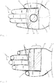
- FIG 2 a hand 6 of a user 2 is shown, which shows a support device 3, shown here hatched, with an alarm device 4.
- the alarm device 4 and the trigger 5 are arranged on the palm 8 visible here.
- the carrying device 3 has a belt device 16.
- the band device 16 can be designed as an (elastic) band 18.
- the large-area trigger 5 can be actuated at any time with almost all fingers 11 and the thumb 12.
- FIG 3 the back of the hand 9 of a hand 6 of a user 2 is shown.
- the hinge device 16 shown hatched is here in the variant made significantly narrower than in the embodiment according to Figure 2 and completely and completely encloses the metacarpal 7 and in particular the metacarpal bones.
- the knuckles 13 remain free here.
- the fingers 11 and the thumb 12 can move freely, however, so that there is practically no impairment of the movement.
- FIG 4 a perspective schematic representation of a variant of an alarm device 4 of the alarm system 1 according to the invention is illustrated.
- An alarm device 4 is let into or integrated into the carrying device 3.
- the carrying device 3 here consists of a flexible material 14 and is designed as a hose 19.
- the flexible material 14 can consist of fabric or a rubber material or the like or comprise such a material.
- the trigger 5 of the alarm device 4 takes up a large part of the surface 22a of the housing 22 of the alarm device.
- a data interface 29 and an energy source, here in the form of a battery 36, are shown schematically within the housing 22.
- an acoustic unit 32 and / or a video unit 33 can be integrated in particular on the opposite side on the back of the hand 9.
- data can be captured better when the trigger is triggered, since the trigger 5 is covered by the fingers.
- At least one acoustic unit 32 for recording the ambient noise or also for outputting warning signals can also be accommodated in the alarm device 4.
- a control unit 37 is provided and a vibration unit 38 can be provided. Information such as an incoming telephone call or an incoming notification on the connected mobile radio device could be communicated to the user 2 by the vibration unit 38.
- the control unit essentially coordinates the data flow between the mobile radio device 30 and the alarm device.
- the control unit 37 can also control the video unit 33 and the acoustic unit 32 of the mobile radio device 30 here.
- FIG 5 is a schematic view of a further embodiment of the alarm device 4 and the support device 3 of an alarm system 1 according to the invention in a sectional view.
- the carrying device 3 here comprises a bracket device 17.
- the brackets 20 are through a one end Joint 21 connected.
- the bracket device 17 as a whole can be surrounded by an elastic element 18. It is also possible that an elastic element 18 connects the brackets 20 at the lower opening here or that the brackets consist at least partially of an elastic and / or flexible material.
- the closure and thus the secure hold of the carrying device 3 are achieved by the closing element 15, here in the form of a Velcro fastener 15a or a push button 15a.
- the alarm device 4 has rounded edges 26 on the surface 22a of the housing 22, which are intended to prevent injury in the event of a fall.
- the trigger is designed as a mechanical element 28.
- the actual housing can be encased in an elastic sleeve, for example made of silicone or the like.
- FIG 6 a schematic plan view of an alarm device 4 is shown.
- the alarm device 4 is made here of an elastic material 25 and has a maximum diameter 27.
- Below the trigger 5, the schematically illustrated data interface 29, a possible acoustic unit 32, a possible video unit 33 and an energy source are shown here in the form of a battery 36.
- the alarm device 4 here also comprises a control unit 37 and a vibration unit 38.
- the control unit 37 is suitable and designed to detect multiple actuation of the trigger 5. Multiple false tripping can be effectively prevented here by repeated actuation of the trigger in quick succession, in particular in immediate succession.
- the carrying device 3 is designed as a band 18 or a cloth tube which completely surrounds the metacarpal 7 and whose low elastic properties enable it to be held on the hand 6 comfortably.
- the alarm device 4 finally comprises a trigger 5, a data interface 29 with a transmitter unit, an energy source here in the form of a battery 36 and possibly a loudspeaker which can emit an acoustic alarm tone in the event of an alarm.
- a trigger 5 a data interface 29 with a transmitter unit, an energy source here in the form of a battery 36 and possibly a loudspeaker which can emit an acoustic alarm tone in the event of an alarm.
- the alarm device 4 particularly preferably has a very low weight and very small geometric dimensions with a diameter 27 of less than 5.0 cm or 4.5 cm.
- the alarm device 4 is preferably designed roughly disk-like in all of its configurations and has a height which is (considerably) less than the diameter.
- a ratio of the diameter 27 of the alarm device 4 (or of the trigger 5) to the height of the alarm device 4 is preferably greater than 3: 2 and in particular greater than 2: 1.
- the data interface 29 is designed in all configurations in particular as a Bluetooth interface or as an interface with ANT +, ZigBee, Wlan or the like.
- the invention provides an alarm system 1 which is worn on the metacarpal 7 and z. B. is fixed by cloth and / or tape and is designed in particular as an elastic textile tape.
- An alarm device 4 is arranged centrally in the palm of the hand 8 so that the exposed trigger 5 can be actuated by bending a finger or, for example, solely by closing the hand 6 or by forming a fist.
- the alarm device 4 is preferably wireless z. B. coupled to a mobile device 30 via Bluetooth.
- Optional additional devices such as a hair tie device 23 or a head lamp device 24 or other devices can be integrated into the system.
- the information can be transmitted to the mobile radio device 30 (in particular by radio signal). At least one stored contact is notified and location information is transmitted to the contact. An audible alarm tone is preferred by the Alarm device 4 and / or the mobile radio device 30 and / or an additional device output.
- Various presettable and changeable contacts can also be notified after a pre-programmable waiting time after activating the alarm from a group of notification elements consisting of a telephone connection, SMS, email and messenger message or another protocol.
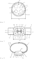
- FIG 7 shows a schematic front view of yet another exemplary embodiment of the alarm system 1.
- the alarm device 4 here has a rounded housing 22 which is made somewhat longer than it is wide. The case is about 30% longer than it is wide. The edges 26 and corners are rounded. The underside of the housing resting on the palm 8 and the opposite upper side of the housing 22 are arched. As a result, the alarm device 4 rests particularly well on the palm 8 of the hand.
- the alarm device is advantageously received in the palm 8 and enclosed by the palm 8.
- the alarm device 4 is thus advantageously adapted to the natural shape of the palm 8. As a result, the alarm device 4 is guided particularly well and safely in the palm of the hand 8 even with rapid movements of the hand 6. Relative movements are minimized.
- the alarm device 4 all necessary components and circuits are included here. These include above all the large-area trigger 5 and the data interface 29.
- a connection to the mobile radio device 30 is established and maintained via the data interface 29.
- At least one acoustic unit 32 is preferably included.
- the acoustic unit 32 can be used for sound output in order to output an alarm sound. It is also possible for the acoustic unit or a further acoustic unit 32 to be used to record ambient noises.
- a vibration unit 38 can also be included.
- An optional video unit 33 is possible.
- the trigger 5 is designed as a mechanical button, which takes up a large part of the upper surface and here approx. 75% of the surface 22a of the housing 22.
- the trigger is convexly curved in profile to match the surface 22a of the housing 22. This advantageously makes it possible for all fingers 11 and thumb 12 of hand 6 of a user 2 to reach the trigger easily.
- the alarm device 4 has a maximum diameter between 3 cm and 5 cm and here of approximately 4 cm.
- the alarm device 4 can thus advantageously be received within the palm 8 of the hand 6.
- the alarm device 4 including the carrying device 3 has a weight of between about 40 grams and 100 grams and here of less than 60 grams, depending on the equipment.
- the alarm device itself weighs less than 60 grams. As a result of these properties, the alarm device 4 can be worn effortlessly and unnoticed for several hours by a user 2 without being perceived as annoying.
- the alarm device 4 is arranged on the carrying device 3 and is detachably connected to the carrying device 3.
- the support device 3 is designed here as a band device 16, which consists of a band 18 made of a flexible material 14, such as a plastic.
- the band 18 can comprise an elastic fabric.
- Figure 8 are the carrying device 3 and the alarm device 4 according to Figure 7 shown purely schematically in a side view.
- the rounded edges 26 and the rounded convex shape of the housing 22 can be seen particularly well.
- the housing 22 of the alarm device 4 has a type of teardrop shape which can be received particularly well in the palm 8 of the hand 6 of a user 2.
- the housing 22 is here preferably designed essentially mirror-symmetrically, so that the lower side and the upper side are convex and radii of curvature greater than 5 mm and in particular greater than 7 mm at the transition from the upper side or have underside to the respective side surfaces.
- the convex surface of the trigger can be reached particularly well by all fingers 11 and the thumb 12 of the hand 6. This is particularly advantageous in the event of an alarm, since the force is particularly advantageously transmitted to the convex trigger 5 by a finger 11 or the thumb 12. A malfunction, i.e. H. failure to operate when the trigger 5 is pressed is reliably prevented. This is particularly important for reliable functioning of the alarm device 4 in all dangerous situations.
- the support device 3 which is designed here as a belt device 16, is connected to the housing 22 on both sides thereof.
- a closing element 15 in the form of a buckle or the like is arranged on the right side.
- the strap 18 is passed through the buckle.
- the buckle is designed like a backpack and its shape prevents the strap 18 from loosening.
- Figure 9 shows the carrying device 3 and the alarm device 4 Figure 7 in a perspective view.
- the rounded edges 26 of the housing 22 are clearly visible again.
- the band device 18 is approximately 20% to 30% narrower than the alarm device 4. A uniform overall effect is created.
- the control unit 37 is provided and designed to control and monitor the functions of the alarm system 1.
- the control unit 37 is therefore able, in addition to a simple actuation of the trigger 5, to recognize multiple actuations which differ in the number of actuations and their individual time lengths. This prevents multiple alarms from being triggered if the trigger is pressed irregularly at short intervals.
- a preprogrammed sequence of Actuations a telephone connection can be established directly through a connected mobile radio device 30 without a time delay. This primarily makes it possible to adapt the function of the alarm device to the personal needs of the user 2.
- the vibration unit 38 gives feedback to the user 2 by vibration as to whether an alarm was triggered by the actuation.
- the alarm system 1 here also includes a headset, which is not shown, so that the user 2 can telephone while jogging.
- other functions are possible that are not described in detail here, but are based on the same principle.
- Figure 10 shows the alarm device 4 according to Figure 7 in an open state with a hand strap 39 to additionally secure the alarm device 4 to the hand.
- the hand strap 39 is connected to the alarm device 4.
- the hand strap 39 is connected to a cable switch 39 inside the alarm device 4.
- the cable switch 39 is also used to operate the trigger 5, but could also be connected to a separate trigger.
- the hand strap 39 can advantageously be worn around the hand 6 and in particular around the wrist.
- the hand strap 39 is here securely and positively arranged around the mechanical trigger 5 included.
- the hand strap 39 and the cable switch 39 are also designed as a trigger 5. If the alarm device 4 is forcibly stolen by the hand 6 of the user 2, the trigger 5 can be actuated. A particularly reliable function of the alarm system 1 is thus guaranteed.
- the housing 22 of the alarm device 4 can be at least partially opened as shown.
- the rope of the hand strap 39 of the rope switch 39 is wrapped around the trigger 5 laid around. After the housing 22 has been closed, the assembly is complete.
- the size of the hand strap 39 can be specifically adapted to a user 2 by means of the setting element 39.
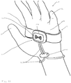
- FIG 11 the carrying device 3 with the alarm device 4 is shown in the intended use directly on the hand 6 of a user 2.
- the carrying device 3 completely encloses the metacarpal 7 of the hand 6 of the user 2.
- the alarm device 4 is received within the palm 8.
- the rounded edges 26 of the housing 22 follow the natural shape of the palm 8.
- the hand strap 39 wraps around the wrist of the hand 6 of the user 2.
- the setting element 39a enables the size of the hand strap 39 to be adjusted.
- the alarm device 4 is accommodated in the middle of the palm 8 and can be reached immediately and directly by practically every finger 11 and the thumb 12. In a dangerous situation such as an attack, the alarm system 1 can thus be operated directly and immediately with one hand.
- a video and / or audio recording is started immediately by a mobile radio device 30 connected via the data interface 29, which is transmitted locally and externally to a database 35 for storage.
- feedback is given to the user 2 about the actuation of the trigger 5 via the vibration unit 38 by means of vibration of the alarm device 4.
- the control unit 37 After a set waiting time, such as about 15 seconds or one minute, the control unit 37 initiates the establishment of a telephone connection to previously established emergency contacts or to an emergency call center.
Landscapes
- Physics & Mathematics (AREA)
- General Physics & Mathematics (AREA)
- Engineering & Computer Science (AREA)
- Computer Security & Cryptography (AREA)
- Business, Economics & Management (AREA)
- Emergency Management (AREA)
- Alarm Systems (AREA)
- Telephone Function (AREA)
Applications Claiming Priority (1)
| Application Number | Priority Date | Filing Date | Title |
|---|---|---|---|
| DE202019101983.2U DE202019101983U1 (de) | 2019-04-05 | 2019-04-05 | Alarmsystem für Jogger |
Publications (2)
| Publication Number | Publication Date |
|---|---|
| EP3721741A1 true EP3721741A1 (fr) | 2020-10-14 |
| EP3721741B1 EP3721741B1 (fr) | 2021-07-28 |
Family
ID=70224295
Family Applications (1)
| Application Number | Title | Priority Date | Filing Date |
|---|---|---|---|
| EP20168315.8A Active EP3721741B1 (fr) | 2019-04-05 | 2020-04-06 | Système d'alarme pour joggeurs |
Country Status (2)
| Country | Link |
|---|---|
| EP (1) | EP3721741B1 (fr) |
| DE (2) | DE202019101983U1 (fr) |
Cited By (3)
| Publication number | Priority date | Publication date | Assignee | Title |
|---|---|---|---|---|
| WO2023001335A1 (fr) | 2021-07-22 | 2023-01-26 | Not Just A Jewel GmbH | Accessoire qui peut être porté au poignet et se présente sous la forme d'un bijou |
| CN116645786A (zh) * | 2023-07-24 | 2023-08-25 | 山东省第二人民医院(山东省耳鼻喉医院、山东省耳鼻喉研究所) | 一种摔倒报警检测装置 |
| EP4310809A1 (fr) * | 2022-07-18 | 2024-01-24 | JT International SA | Dispositif de vapotage électronique doté d'une fonctionnalité anti-agression |
Families Citing this family (1)
| Publication number | Priority date | Publication date | Assignee | Title |
|---|---|---|---|---|
| CN116453291B (zh) * | 2023-04-11 | 2024-06-21 | 上海慰宁健康管理咨询有限公司南京分公司 | 一种基于随身通的智能预警方法 |
Citations (9)
| Publication number | Priority date | Publication date | Assignee | Title |
|---|---|---|---|---|
| DE2910016C2 (de) | 1978-03-15 | 1984-09-27 | Electronique Marcel Dassault S.A., Paris | Notrufvorrichtung |
| WO1995006302A1 (fr) | 1993-08-27 | 1995-03-02 | Alertcall, Inc. | Appareil d'alarme personnel |
| GB2295910A (en) * | 1994-12-06 | 1996-06-12 | Telko Inc | Personal alarm |
| WO2008113846A1 (fr) | 2007-03-21 | 2008-09-25 | Intermultilock Ab | Protection par flash |
| DE202009008030U1 (de) * | 2009-06-09 | 2009-09-24 | Gehde, Heinz | Alarmgeber |
| DE102012024000A1 (de) * | 2012-12-06 | 2014-06-12 | Cosi - Elektronik Gmbh | Notrufsender |
| US20150065082A1 (en) * | 2013-08-27 | 2015-03-05 | Akhil SEHGAL | Personal safety device, system and a method |
| US20150109123A1 (en) | 2013-03-04 | 2015-04-23 | Fear-Less Solutions, Inc. | Interchangeable personal security device with a communication accessory |
| EP3255619A1 (fr) | 2016-06-10 | 2017-12-13 | Micro APPS Group Inventions LLC | Dispositif de sécurité personnel sans fil |
-
2019
- 2019-04-05 DE DE202019101983.2U patent/DE202019101983U1/de not_active Expired - Lifetime
-
2020
- 2020-04-06 DE DE102020109586.4A patent/DE102020109586A1/de not_active Withdrawn
- 2020-04-06 EP EP20168315.8A patent/EP3721741B1/fr active Active
Patent Citations (9)
| Publication number | Priority date | Publication date | Assignee | Title |
|---|---|---|---|---|
| DE2910016C2 (de) | 1978-03-15 | 1984-09-27 | Electronique Marcel Dassault S.A., Paris | Notrufvorrichtung |
| WO1995006302A1 (fr) | 1993-08-27 | 1995-03-02 | Alertcall, Inc. | Appareil d'alarme personnel |
| GB2295910A (en) * | 1994-12-06 | 1996-06-12 | Telko Inc | Personal alarm |
| WO2008113846A1 (fr) | 2007-03-21 | 2008-09-25 | Intermultilock Ab | Protection par flash |
| DE202009008030U1 (de) * | 2009-06-09 | 2009-09-24 | Gehde, Heinz | Alarmgeber |
| DE102012024000A1 (de) * | 2012-12-06 | 2014-06-12 | Cosi - Elektronik Gmbh | Notrufsender |
| US20150109123A1 (en) | 2013-03-04 | 2015-04-23 | Fear-Less Solutions, Inc. | Interchangeable personal security device with a communication accessory |
| US20150065082A1 (en) * | 2013-08-27 | 2015-03-05 | Akhil SEHGAL | Personal safety device, system and a method |
| EP3255619A1 (fr) | 2016-06-10 | 2017-12-13 | Micro APPS Group Inventions LLC | Dispositif de sécurité personnel sans fil |
Cited By (6)
| Publication number | Priority date | Publication date | Assignee | Title |
|---|---|---|---|---|
| WO2023001335A1 (fr) | 2021-07-22 | 2023-01-26 | Not Just A Jewel GmbH | Accessoire qui peut être porté au poignet et se présente sous la forme d'un bijou |
| DE102021119079A1 (de) | 2021-07-22 | 2023-01-26 | Not Just A Jewel GmbH | Am Handgelenk tragbares und als Schmuckstück ausgebildetes Wearable |
| DE102021119079B4 (de) | 2021-07-22 | 2023-06-01 | Not Just A Jewel GmbH | Am Handgelenk tragbares und als Schmuckstück ausgebildetes Wearable |
| EP4310809A1 (fr) * | 2022-07-18 | 2024-01-24 | JT International SA | Dispositif de vapotage électronique doté d'une fonctionnalité anti-agression |
| CN116645786A (zh) * | 2023-07-24 | 2023-08-25 | 山东省第二人民医院(山东省耳鼻喉医院、山东省耳鼻喉研究所) | 一种摔倒报警检测装置 |
| CN116645786B (zh) * | 2023-07-24 | 2023-12-19 | 山东省第二人民医院(山东省耳鼻喉医院、山东省耳鼻喉研究所) | 一种摔倒报警检测装置 |
Also Published As
| Publication number | Publication date |
|---|---|
| EP3721741B1 (fr) | 2021-07-28 |
| DE102020109586A1 (de) | 2020-10-08 |
| DE202019101983U1 (de) | 2020-07-09 |
Similar Documents
| Publication | Publication Date | Title |
|---|---|---|
| EP3721741B1 (fr) | Système d'alarme pour joggeurs | |
| EP2394253B1 (fr) | Appareil d'appels d'urgence | |
| DE60021125T2 (de) | Warnsystem mit sendergesteuerter mehrfachauslösung und tragbarem empfänger-vibrator | |
| DE69926290T2 (de) | Tragbares Kommunikationsgerät mit Anordnung zum Knochenleitungshören | |
| EP3571681B1 (fr) | Sirène portable et appareil d'appel d'urgence ainsi que leur combinaison | |
| DE69724079T2 (de) | Armbandtelefongerät | |
| WO2001035791A2 (fr) | Ceinture de securite | |
| DE102012024000B4 (de) | Notrufsender | |
| US10881326B1 (en) | Wearable safety device | |
| DE29922991U1 (de) | Sicherheitsgürtel | |
| DE4211386A1 (de) | Alarmeinrichtung | |
| DE202017000492U1 (de) | Armband | |
| AT517097B1 (de) | Notrufgerät | |
| DE102021119079B4 (de) | Am Handgelenk tragbares und als Schmuckstück ausgebildetes Wearable | |
| DE10004041A1 (de) | Personen-Notruf-System und Verfahren zur Alarmübermittlung eines Personen-Notruf-Systems | |
| DE202016005422U1 (de) | Multifunktions-Abwehrsystem. Handhalterung, zur Aufnahme von Schutzspray(Reizgas, Pfefferspray, Farbspray etc.) mit integriertem akustischen Alarmgeber, GPS-Ortung und Not-SMS Sendung bei Auslösen des Systems. | |
| EP2378496A2 (fr) | Appareil d'appel d'urgence | |
| DE20107966U1 (de) | Mobiles Nothilfegerät auf fernmeldetechnischer Grundlage (I) | |
| JP2847478B2 (ja) | 埋没脱出器 | |
| EP3396644A2 (fr) | Unité de signalisation mobile, unité de commande mobile ainsi que système de défense mobile | |
| DE10305934B4 (de) | Mobiles Körperphon | |
| JP3122297U (ja) | 視聴覚データの記録装置 | |
| DE202005013367U1 (de) | Alarmvorrichtung | |
| DE20107967U1 (de) | Mobiles Nothilfegerät auf fernmeldetechnischer Grundlage (II) | |
| DE20019401U1 (de) | Wecksystem mit Vibrationsalarm |
Legal Events
| Date | Code | Title | Description |
|---|---|---|---|
| PUAI | Public reference made under article 153(3) epc to a published international application that has entered the european phase |
Free format text: ORIGINAL CODE: 0009012 |
|
| STAA | Information on the status of an ep patent application or granted ep patent |
Free format text: STATUS: THE APPLICATION HAS BEEN PUBLISHED |
|
| AK | Designated contracting states |
Kind code of ref document: A1 Designated state(s): AL AT BE BG CH CY CZ DE DK EE ES FI FR GB GR HR HU IE IS IT LI LT LU LV MC MK MT NL NO PL PT RO RS SE SI SK SM TR |
|
| AX | Request for extension of the european patent |
Extension state: BA ME |
|
| STAA | Information on the status of an ep patent application or granted ep patent |
Free format text: STATUS: REQUEST FOR EXAMINATION WAS MADE |
|
| 17P | Request for examination filed |
Effective date: 20201009 |
|
| RBV | Designated contracting states (corrected) |
Designated state(s): AL AT BE BG CH CY CZ DE DK EE ES FI FR GB GR HR HU IE IS IT LI LT LU LV MC MK MT NL NO PL PT RO RS SE SI SK SM TR |
|
| GRAP | Despatch of communication of intention to grant a patent |
Free format text: ORIGINAL CODE: EPIDOSNIGR1 |
|
| STAA | Information on the status of an ep patent application or granted ep patent |
Free format text: STATUS: GRANT OF PATENT IS INTENDED |
|
| RIC1 | Information provided on ipc code assigned before grant |
Ipc: A44C 5/00 20060101AFI20201130BHEP Ipc: G08B 25/01 20060101ALI20201130BHEP |
|
| GRAS | Grant fee paid |
Free format text: ORIGINAL CODE: EPIDOSNIGR3 |
|
| INTG | Intention to grant announced |
Effective date: 20201223 |
|
| GRAA | (expected) grant |
Free format text: ORIGINAL CODE: 0009210 |
|
| STAA | Information on the status of an ep patent application or granted ep patent |
Free format text: STATUS: THE PATENT HAS BEEN GRANTED |
|
| AK | Designated contracting states |
Kind code of ref document: B1 Designated state(s): AL AT BE BG CH CY CZ DE DK EE ES FI FR GB GR HR HU IE IS IT LI LT LU LV MC MK MT NL NO PL PT RO RS SE SI SK SM TR |
|
| REG | Reference to a national code |
Ref country code: GB Ref legal event code: FG4D Free format text: NOT ENGLISH |
|
| REG | Reference to a national code |
Ref country code: CH Ref legal event code: EP |
|
| REG | Reference to a national code |
Ref country code: DE Ref legal event code: R096 Ref document number: 502020000106 Country of ref document: DE |
|
| REG | Reference to a national code |
Ref country code: AT Ref legal event code: REF Ref document number: 1413907 Country of ref document: AT Kind code of ref document: T Effective date: 20210815 |
|
| REG | Reference to a national code |
Ref country code: IE Ref legal event code: FG4D Free format text: LANGUAGE OF EP DOCUMENT: GERMAN |
|
| REG | Reference to a national code |
Ref country code: LT Ref legal event code: MG9D |
|
| REG | Reference to a national code |
Ref country code: NL Ref legal event code: MP Effective date: 20210728 |
|
| PG25 | Lapsed in a contracting state [announced via postgrant information from national office to epo] |
Ref country code: FI Free format text: LAPSE BECAUSE OF FAILURE TO SUBMIT A TRANSLATION OF THE DESCRIPTION OR TO PAY THE FEE WITHIN THE PRESCRIBED TIME-LIMIT Effective date: 20210728 Ref country code: HR Free format text: LAPSE BECAUSE OF FAILURE TO SUBMIT A TRANSLATION OF THE DESCRIPTION OR TO PAY THE FEE WITHIN THE PRESCRIBED TIME-LIMIT Effective date: 20210728 Ref country code: NL Free format text: LAPSE BECAUSE OF FAILURE TO SUBMIT A TRANSLATION OF THE DESCRIPTION OR TO PAY THE FEE WITHIN THE PRESCRIBED TIME-LIMIT Effective date: 20210728 Ref country code: NO Free format text: LAPSE BECAUSE OF FAILURE TO SUBMIT A TRANSLATION OF THE DESCRIPTION OR TO PAY THE FEE WITHIN THE PRESCRIBED TIME-LIMIT Effective date: 20211028 Ref country code: PT Free format text: LAPSE BECAUSE OF FAILURE TO SUBMIT A TRANSLATION OF THE DESCRIPTION OR TO PAY THE FEE WITHIN THE PRESCRIBED TIME-LIMIT Effective date: 20211129 Ref country code: LT Free format text: LAPSE BECAUSE OF FAILURE TO SUBMIT A TRANSLATION OF THE DESCRIPTION OR TO PAY THE FEE WITHIN THE PRESCRIBED TIME-LIMIT Effective date: 20210728 Ref country code: BG Free format text: LAPSE BECAUSE OF FAILURE TO SUBMIT A TRANSLATION OF THE DESCRIPTION OR TO PAY THE FEE WITHIN THE PRESCRIBED TIME-LIMIT Effective date: 20211028 Ref country code: ES Free format text: LAPSE BECAUSE OF FAILURE TO SUBMIT A TRANSLATION OF THE DESCRIPTION OR TO PAY THE FEE WITHIN THE PRESCRIBED TIME-LIMIT Effective date: 20210728 Ref country code: SE Free format text: LAPSE BECAUSE OF FAILURE TO SUBMIT A TRANSLATION OF THE DESCRIPTION OR TO PAY THE FEE WITHIN THE PRESCRIBED TIME-LIMIT Effective date: 20210728 Ref country code: RS Free format text: LAPSE BECAUSE OF FAILURE TO SUBMIT A TRANSLATION OF THE DESCRIPTION OR TO PAY THE FEE WITHIN THE PRESCRIBED TIME-LIMIT Effective date: 20210728 |
|
| PG25 | Lapsed in a contracting state [announced via postgrant information from national office to epo] |
Ref country code: PL Free format text: LAPSE BECAUSE OF FAILURE TO SUBMIT A TRANSLATION OF THE DESCRIPTION OR TO PAY THE FEE WITHIN THE PRESCRIBED TIME-LIMIT Effective date: 20210728 Ref country code: LV Free format text: LAPSE BECAUSE OF FAILURE TO SUBMIT A TRANSLATION OF THE DESCRIPTION OR TO PAY THE FEE WITHIN THE PRESCRIBED TIME-LIMIT Effective date: 20210728 Ref country code: GR Free format text: LAPSE BECAUSE OF FAILURE TO SUBMIT A TRANSLATION OF THE DESCRIPTION OR TO PAY THE FEE WITHIN THE PRESCRIBED TIME-LIMIT Effective date: 20211029 |
|
| PG25 | Lapsed in a contracting state [announced via postgrant information from national office to epo] |
Ref country code: DK Free format text: LAPSE BECAUSE OF FAILURE TO SUBMIT A TRANSLATION OF THE DESCRIPTION OR TO PAY THE FEE WITHIN THE PRESCRIBED TIME-LIMIT Effective date: 20210728 |
|
| REG | Reference to a national code |
Ref country code: DE Ref legal event code: R097 Ref document number: 502020000106 Country of ref document: DE |
|
| PG25 | Lapsed in a contracting state [announced via postgrant information from national office to epo] |
Ref country code: SM Free format text: LAPSE BECAUSE OF FAILURE TO SUBMIT A TRANSLATION OF THE DESCRIPTION OR TO PAY THE FEE WITHIN THE PRESCRIBED TIME-LIMIT Effective date: 20210728 Ref country code: SK Free format text: LAPSE BECAUSE OF FAILURE TO SUBMIT A TRANSLATION OF THE DESCRIPTION OR TO PAY THE FEE WITHIN THE PRESCRIBED TIME-LIMIT Effective date: 20210728 Ref country code: RO Free format text: LAPSE BECAUSE OF FAILURE TO SUBMIT A TRANSLATION OF THE DESCRIPTION OR TO PAY THE FEE WITHIN THE PRESCRIBED TIME-LIMIT Effective date: 20210728 Ref country code: EE Free format text: LAPSE BECAUSE OF FAILURE TO SUBMIT A TRANSLATION OF THE DESCRIPTION OR TO PAY THE FEE WITHIN THE PRESCRIBED TIME-LIMIT Effective date: 20210728 Ref country code: CZ Free format text: LAPSE BECAUSE OF FAILURE TO SUBMIT A TRANSLATION OF THE DESCRIPTION OR TO PAY THE FEE WITHIN THE PRESCRIBED TIME-LIMIT Effective date: 20210728 Ref country code: AL Free format text: LAPSE BECAUSE OF FAILURE TO SUBMIT A TRANSLATION OF THE DESCRIPTION OR TO PAY THE FEE WITHIN THE PRESCRIBED TIME-LIMIT Effective date: 20210728 |
|
| PLBE | No opposition filed within time limit |
Free format text: ORIGINAL CODE: 0009261 |
|
| STAA | Information on the status of an ep patent application or granted ep patent |
Free format text: STATUS: NO OPPOSITION FILED WITHIN TIME LIMIT |
|
| 26N | No opposition filed |
Effective date: 20220429 |
|
| PG25 | Lapsed in a contracting state [announced via postgrant information from national office to epo] |
Ref country code: IT Free format text: LAPSE BECAUSE OF FAILURE TO SUBMIT A TRANSLATION OF THE DESCRIPTION OR TO PAY THE FEE WITHIN THE PRESCRIBED TIME-LIMIT Effective date: 20210728 |
|
| REG | Reference to a national code |
Ref country code: BE Ref legal event code: MM Effective date: 20220430 |
|
| PG25 | Lapsed in a contracting state [announced via postgrant information from national office to epo] |
Ref country code: MC Free format text: LAPSE BECAUSE OF FAILURE TO SUBMIT A TRANSLATION OF THE DESCRIPTION OR TO PAY THE FEE WITHIN THE PRESCRIBED TIME-LIMIT Effective date: 20210728 Ref country code: LU Free format text: LAPSE BECAUSE OF NON-PAYMENT OF DUE FEES Effective date: 20220406 Ref country code: FR Free format text: LAPSE BECAUSE OF NON-PAYMENT OF DUE FEES Effective date: 20220430 |
|
| PG25 | Lapsed in a contracting state [announced via postgrant information from national office to epo] |
Ref country code: BE Free format text: LAPSE BECAUSE OF NON-PAYMENT OF DUE FEES Effective date: 20220430 |
|
| PG25 | Lapsed in a contracting state [announced via postgrant information from national office to epo] |
Ref country code: IE Free format text: LAPSE BECAUSE OF NON-PAYMENT OF DUE FEES Effective date: 20220406 |
|
| PG25 | Lapsed in a contracting state [announced via postgrant information from national office to epo] |
Ref country code: MK Free format text: LAPSE BECAUSE OF FAILURE TO SUBMIT A TRANSLATION OF THE DESCRIPTION OR TO PAY THE FEE WITHIN THE PRESCRIBED TIME-LIMIT Effective date: 20210728 Ref country code: CY Free format text: LAPSE BECAUSE OF FAILURE TO SUBMIT A TRANSLATION OF THE DESCRIPTION OR TO PAY THE FEE WITHIN THE PRESCRIBED TIME-LIMIT Effective date: 20210728 |
|
| PG25 | Lapsed in a contracting state [announced via postgrant information from national office to epo] |
Ref country code: HU Free format text: LAPSE BECAUSE OF FAILURE TO SUBMIT A TRANSLATION OF THE DESCRIPTION OR TO PAY THE FEE WITHIN THE PRESCRIBED TIME-LIMIT; INVALID AB INITIO Effective date: 20200406 |
|
| PGFP | Annual fee paid to national office [announced via postgrant information from national office to epo] |
Ref country code: DE Payment date: 20240517 Year of fee payment: 5 |
|
| PGFP | Annual fee paid to national office [announced via postgrant information from national office to epo] |
Ref country code: CH Payment date: 20240501 Year of fee payment: 5 |
|
| PG25 | Lapsed in a contracting state [announced via postgrant information from national office to epo] |
Ref country code: MT Free format text: LAPSE BECAUSE OF FAILURE TO SUBMIT A TRANSLATION OF THE DESCRIPTION OR TO PAY THE FEE WITHIN THE PRESCRIBED TIME-LIMIT Effective date: 20210728 |
|
| GBPC | Gb: european patent ceased through non-payment of renewal fee |
Effective date: 20240406 |
|
| PG25 | Lapsed in a contracting state [announced via postgrant information from national office to epo] |
Ref country code: GB Free format text: LAPSE BECAUSE OF NON-PAYMENT OF DUE FEES Effective date: 20240406 |
|
| PG25 | Lapsed in a contracting state [announced via postgrant information from national office to epo] |
Ref country code: GB Free format text: LAPSE BECAUSE OF NON-PAYMENT OF DUE FEES Effective date: 20240406 |
|
| PGFP | Annual fee paid to national office [announced via postgrant information from national office to epo] |
Ref country code: AT Payment date: 20250721 Year of fee payment: 5 |
|
| REG | Reference to a national code |
Ref country code: DE Ref legal event code: R119 Ref document number: 502020000106 Country of ref document: DE |
|
| REG | Reference to a national code |
Ref country code: CH Ref legal event code: H13 Free format text: ST27 STATUS EVENT CODE: U-0-0-H10-H13 (AS PROVIDED BY THE NATIONAL OFFICE) Effective date: 20251125 |
|
| PG25 | Lapsed in a contracting state [announced via postgrant information from national office to epo] |
Ref country code: TR Free format text: LAPSE BECAUSE OF FAILURE TO SUBMIT A TRANSLATION OF THE DESCRIPTION OR TO PAY THE FEE WITHIN THE PRESCRIBED TIME-LIMIT Effective date: 20210728 |
|
| PG25 | Lapsed in a contracting state [announced via postgrant information from national office to epo] |
Ref country code: DE Free format text: LAPSE BECAUSE OF NON-PAYMENT OF DUE FEES Effective date: 20251104 |
|
| PG25 | Lapsed in a contracting state [announced via postgrant information from national office to epo] |
Ref country code: CH Free format text: LAPSE BECAUSE OF NON-PAYMENT OF DUE FEES Effective date: 20250430 |