EP3721760B1 - Heissluftkochgerät mit vorderer öffnung zum einsetzen und entfernen eines kochbehälters - Google Patents
Heissluftkochgerät mit vorderer öffnung zum einsetzen und entfernen eines kochbehälters Download PDFInfo
- Publication number
- EP3721760B1 EP3721760B1 EP20169044.3A EP20169044A EP3721760B1 EP 3721760 B1 EP3721760 B1 EP 3721760B1 EP 20169044 A EP20169044 A EP 20169044A EP 3721760 B1 EP3721760 B1 EP 3721760B1
- Authority
- EP
- European Patent Office
- Prior art keywords
- cooking
- housing
- base
- cooking vessel
- hot air
- Prior art date
- Legal status (The legal status is an assumption and is not a legal conclusion. Google has not performed a legal analysis and makes no representation as to the accuracy of the status listed.)
- Active
Links
Images




Classifications
-
- A—HUMAN NECESSITIES
- A47—FURNITURE; DOMESTIC ARTICLES OR APPLIANCES; COFFEE MILLS; SPICE MILLS; SUCTION CLEANERS IN GENERAL
- A47J—KITCHEN EQUIPMENT; COFFEE MILLS; SPICE MILLS; APPARATUS FOR MAKING BEVERAGES
- A47J37/00—Baking; Roasting; Grilling; Frying
- A47J37/06—Roasters; Grills; Sandwich grills
- A47J37/0623—Small-size cooking ovens, i.e. defining an at least partially closed cooking cavity
- A47J37/0629—Small-size cooking ovens, i.e. defining an at least partially closed cooking cavity with electric heating elements
- A47J37/0641—Small-size cooking ovens, i.e. defining an at least partially closed cooking cavity with electric heating elements with forced air circulation, e.g. air fryers
-
- A—HUMAN NECESSITIES
- A47—FURNITURE; DOMESTIC ARTICLES OR APPLIANCES; COFFEE MILLS; SPICE MILLS; SUCTION CLEANERS IN GENERAL
- A47J—KITCHEN EQUIPMENT; COFFEE MILLS; SPICE MILLS; APPARATUS FOR MAKING BEVERAGES
- A47J37/00—Baking; Roasting; Grilling; Frying
- A47J37/06—Roasters; Grills; Sandwich grills
- A47J37/0623—Small-size cooking ovens, i.e. defining an at least partially closed cooking cavity
- A47J37/0664—Accessories
Definitions
- the present invention relates to hot air cooking appliances which make it possible to cook food by means of a circulation of hot air, said cooking being carried out using very little oil, or even no oil at all.
- Hot air cooking appliances of the type described in the documents US 2013/0180413 A1 Where EP3210507A1 are well known to those skilled in the art, these being generally referred to as “hot air fryer”.
- Such a cooking appliance makes it possible to greatly reduce the quantity of fat, or even to completely eliminate it, during the cooking of food which is carried out simply by means of hot air which circulates in a cooking chamber containing the food to be to cook.
- hot air which circulates in a cooking chamber containing the food to be to cook.
- it is possible to consume more dietetic foods these foods possibly being of plant or animal origin, for example chips, vegetables, meat or fish.
- a hot air cooking appliance generally comprises a closed base which incorporates a removable bowl, said bowl allowing the reception of the food to be cooked, either directly or by placing these foods to be cooked in a removable basket which is itself positioned in the tank. Once the food has been placed in the tank and the latter placed in the base, the cooking appliance is closed to constitute a cooking enclosure incorporating the tank, the possible basket and the food. Hot air then circulates in this cooking chamber by means of a heating block arranged in the upper part of the cooking appliance, above the base, the circulation of hot air making it possible to carry out the heating. cooking food placed in the bowl.
- the heating unit comprises a heating device and an air circulation device making it possible to ensure the circulation of the heated air in the cooking chamber.
- the appliance When the cooking of the food is finished, the appliance is opened and the tank extracted from the base, the cooked food then being transferred to a serving dish which is then placed on the table during the meal.
- traditional cooking appliances require a step of transferring the cooked food from the tank or from the basket possibly incorporated in this tank, to the serving dish which is placed on the table at the time of the meal.
- This transfer of cooked food to a serving dish - which is generally cold - causes the cooked food to cool before consumption. It is also necessary to wash this serving dish after use, in addition to the bowl and possibly the basket of the cooking appliance.
- the document US 2016/015 0915 A1 discloses a cooking appliance comprising a housing having a front opening for receiving a cooking vessel, and two side walls each provided with a free edge contiguous to the front opening and a cutout which is transverse to said side wall and which opens onto said free edge.
- Each of the cutouts is adapted to receive a gripping element of the cooking vessel so as to retain manual access to each gripping element of said cooking vessel via said side walls during the insertion of the cooking vessel into said housing or removal of the cooking receptacle from said housing and is adapted to allow the passage of the gripping elements of the cooking receptacle by letting them protrude outside the side walls when said cooking receptacle is inserted into the housing.
- the invention overcomes the various aforementioned drawbacks existing with traditional hot air cooking appliances and provides numerous advantages which will be explained below.
- the hot air cooking appliance comprises a heating unit arranged in the upper part and a base arranged in part lower, the base comprising a housing above which is the heating block.
- the housing is suitable for receiving a cooking receptacle provided with an upper opening intended to be placed opposite said heating block.
- the base comprises a front opening which communicates with the housing and which is able to allow the passage of the cooking receptacle for its insertion into the housing and its withdrawal therefrom.
- the base comprises two side walls each provided with a free edge contiguous to the front opening and with a cutout which is transverse on said side wall and which opens onto said free edge.
- Each of the cutouts is adapted to receive a gripping element of the cooking vessel so as to retain manual access to each gripping element of said cooking vessel via said side walls during the insertion of the cooking vessel into said housing or removal of the cooking receptacle from said housing and is adapted to allow the passage of the gripping elements of the cooking receptacle by letting them protrude outside the side walls when said cooking receptacle is inserted into the housing.
- the heating unit is mounted on the base in a removable manner, said heating unit being able to be placed directly on an upper opening of a cooking receptacle independently of said base.
- the design of the hot air cooking appliance according to the invention allows the food to be cooked to be placed directly in a cooking vessel which is used not only on the cooking appliance to carry out said cooking by means of the hot air circulating in said cooking vessel by virtue of the heating unit, but also for directly serving at the table without having to transfer the cooked food to an additional serving dish.
- it reduces the amount of dishes to be washed.
- the absence of transfer of the cooked food into a serving dish and the direct use of the cooking vessel which has just been used for cooking and whose wall is still hot allow the cooked food to be preserved. hot until they are served on the plates.
- the permanent presence of this front opening on the base makes it possible to reduce the quantity of material. necessary for the design of the cooking apparatus, which reduces its total cost of manufacture.
- the gripping elements of the cooking vessel can be properly maintained from the outside of the base, throughout the handling of said cooking vessel.
- This removable assembly is implemented thanks to the presence of an assembly device between the heating block and the base.
- the heating block can be removed from the base and placed on a cooking vessel which is placed directly on a table or kitchen surface.
- This cooking receptacle may comprise two gripping elements and be able to be placed in the housing of the base of the cooking appliance, as mentioned above.
- This cooking vessel may on the contrary be of any design, that is to say not adapted to said housing, but be able to receive the heating block; it can for example be a saucepan or a Dutch oven.
- the cooking appliance according to the invention can be marketed independently, the cook being able to use in this case one or more containers which he already has and which are adapted to be each placed in the housing of the base by positioning the two elements of gripping of said container in the cutouts of the side walls of this base, or even to directly receive the heating unit when the latter is removable from the base such as in the aforementioned variant of the cooking appliance.
- the cutouts are able to support the gripping elements of the cooking receptacle when said cooking receptacle is inserted into the housing.
- a base could be provided on the base, said base supporting the cooking receptacle while the gripping elements are simply slipped into the cutouts on the side walls of the base.
- This variant however conditions the height of the container which must be adapted in order to be able to slide the gripping elements into the cutouts when the container rests on the base.
- the base comprises a base arranged under the front opening and the housing.
- the base comprises a guide system capable of aligning the gripping elements of the cooking vessel in height with the cutouts at the start of insertion of the cooking vessel through the front opening. This facilitates the introduction of the container into the housing by correctly positioning the gripping elements of the container vis-à-vis the cutouts on the side walls, in an intuitive manner.
- this guidance system comprises at least one guide ramp, preferably three guide ramps.
- the hot air cooking appliance comprises an elevation system implemented on a base of the base or on the cutouts of the side walls of the base and capable of raising the container by cooking when it is inserted into the housing so as to bring the upper opening of the cooking vessel closer to the heating block.
- the hot air cooking appliance comprises a safety device capable of preventing the insertion of a cooking receptacle into the housing or the removal of a cooking receptacle from the housing.
- the side walls of the base each comprise on their internal face at least one support element capable of receiving a support element of a cooking utensil while keeping said cooking utensil away from the block. of heating.
- the cooking appliance is designed to receive above all a cooking receptacle, but also one or more other cooking utensils, as will appear below.
- the internal faces of the side walls each comprise at least two support elements arranged at different heights on each of said internal faces, said support elements being able to receive one or the other an element d. '' support a cooking utensil by keeping it away from the heating block according to at least two different heights.
- the cooking appliance comprises at least two positions for separating the cooking utensil from the heating block, when it is positioned in the housing.
- the invention also relates to a cooking system which comprises a hot air cooking appliance having one and / or the other of the aforementioned characteristics which are the subject of the invention.
- the cooking system comprises a cooking accessory kit comprising at least one cooking vessel provided with an upper opening and two gripping elements, said at least one cooking vessel being able to be inserted into the housing the base of the hot air cooking appliance by passing through the front opening and placing the two gripping elements respectively in the two cutouts on the side walls of the base of said cooking appliance.
- a sealing system is implemented between the upper opening of the at least one cooking receptacle and the heating block when said at least one cooking receptacle is inserted into the housing.
- This sealing system makes it possible to ensure circulation of hot air in the receptacle thanks to the heating unit, by preventing the escape of this hot air at the level of the junction between the upper opening of the receptacle and the heating block.
- the upper opening of the receptacle being in this case placed near the heating unit to concentrate the circulation of hot air in the receptacle while limiting the leaks of hot air by the space left between the top opening of the container and the heating block.
- this aforementioned sealing system comprises a seal arranged on an edge of the upper opening of the at least one cooking vessel or on an edge of a lower opening of the heating block.
- the gripping elements on the at least one cooking receptacle are flat and the cutouts on the side walls of the base of the cooking appliance have the shape of a slot.
- the at least one cooking receptacle is transparent. This allows visualization of the food during their cooking in the cooking vessel, in particular to monitor said cooking of the food. However, it is possible to envisage an opaque cooking vessel.
- the cooking accessory kit comprises at least one cover suitable for being placed on the upper opening of the at least one cooking receptacle.
- the accessory kit can either comprise as many lids as there are cooking vessels, the covers being adapted to the cooking vessels, or comprise a single cover suitable for all the cooking vessels. Such a cover makes it possible to keep the food warm once cooked and the cooking receptacle placed on the table, while awaiting service on the plates.
- the hot air cooking appliance comprises the aforementioned features consisting in providing on each of the internal faces of the side walls of the base at least one support element.
- the cooking accessory kit comprises at least one cooking utensil complementary to the at least one cooking receptacle, each cooking utensil comprising two support elements able to rest on the at least one support element of the internal faces of the two side walls of the base, so as to maintain said cooking utensil in the housing of the base with a distance from the heating block.
- the at least one cooking utensil is chosen from a grid, a plate and a flat rigid mold provided with imprints. Other cooking utensils could however be envisaged within the framework of the invention.
- appliance is used to denote a hot air cooking appliance 1 according to the invention.
- receptacle is used to denote the cooking receptacle according to the invention.
- same references are used to designate the identical or equivalent characteristics according to the various variant embodiments of the apparatus and of the container.
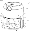
- the device 1 comprises in its upper part a heating block 2 and in its lower part a base 3.
- the base 3 comprises a base 4, two side walls 5, 6, a bottom wall 7 and a front opening 8
- the side walls 5, 6 each comprise a free edge 5a, 6a, said free edges 5a, 6a being contiguous with the front opening 8.
- the base 3 defines a housing 9 located below the heating block 2. This housing 9 allows the reception of a receptacle 10, as will be detailed below.
- the heating block 2 makes it possible to circulate hot air downwards in the direction of the housing 9 so that when the container 10 is placed in said housing 9, said hot air circulates in said container 10.
- the heating block 2 is designed to cycle this hot air so as to heat it and return it to said receptacle 10 placed under said heating block 2.
- This heating block 2 comprises an air inlet, an air heating device of the resistive type (not illustrated) and a device for circulating hot air of the fan type (not illustrated), as already traditionally exists on hot air cooking appliances of the hot air fryer type.
- the appliance 1 preferably provides for ensuring a seal between the heating block 2 and the container 10. when the latter is placed in the housing 9 on the base 3, so as to prevent the hot air circulating in the container 10 from escaping through the top of said container 10.
- a seal 11 can be placed on the edge 12 of the upper opening 13 of the container 10, as illustrated in figure 3 (the seal 11 is shown partially on the edge 12), this seal 11 being arranged to cooperate with the edge 14 of a lower opening 15 on the heating block 2.
- this seal 11 is also possible to consider placing this seal 11 on the edge 14 of the lower opening 15 of the heating block 2 rather than on the edge 12 of the upper opening 13 of the container 10, in particular when several containers 10 having different capacities and / or designed in different materials (stainless steel, transparent or opaque glass, aluminum, etc.) can be used with said device 1.
- This seal 11 will preferably be removable to facilitate cleaning, or even to position it on one or the another of the containers 10 usable with said apparatus 1, when said containers 10 are designed to receive such a seal 11.
- Variants are also possible without sealing between the container 10 and the heating block 2 of the device 1, while maintaining a slight gap 16 between the edge 12 of the upper opening 13 of the container 10 and the edge 14 of the opening. lower 15 of heating block 2, as shown in figure 1 .
- the hot air circulating in the receptacle 10 under the action of the heating block 2 can partially escape through said gap 16 left between said edges 12, 14.
- the side walls 5, 6 of the base 3 each comprise a cutout 17, 18.
- the two cutouts 17, 18 are arranged transversely on the side walls 5, 6 and open out on the free edges 5a, 6a of said side walls 5, 6.
- the container 10 comprises on its contour 19 two gripping elements 20, 21 arranged in opposition (not illustrated on the figure. figure 3 ) and each comprising a flat portion 20a, 21a extending at right angles to the contour 19 and a curved portion 20b, 21b disposed at right angles downward with respect to said flat portion 20a, 21a, so as to ensure a correct grip gripping elements 20, 21 without the risk of them slipping out of the hands during handling of the container 10.
- the cutouts 17, 18 preferably have the shape of a slot, the width of which is slightly greater than the thickness of the flat parts 20a, 21a of the gripping elements 20, 21, which makes it possible to introduce these flat parts 20a, 21a in the cutouts 17, 18 during the insertion of the container 10 in the housing 9, said insertion being done by moving the container 10 to the through the front opening 8.
- the cutouts 17, 18 are preferably slightly flared at the level of the free edges 5a, 6a of the side walls 5, 6 so as to facilitate the introduction of the flat parts 20a, 21a of the gripping elements 20, 21 da ns said cutouts 17, 18.
- the end portions of the flat parts 20a, 21a and the curved parts 20b, 21b protrude from the cutouts 17, 18 and are accessible from the outside of the side walls 5, 6, which allows the gripping elements 20, 21 to be correctly grasped during the insertion of the container 10 into the housing 9 and its withdrawal therefrom.
- the diameter of the contour 19 and / or the length of the flat parts 20a, 21a of the gripping elements 20, 21 on the container 10 are adapted according to the housing 9 and the distance between the two side walls 5, 6 on the base 3.
- the flat parts 20a, 21a of the gripping elements 20, 21 can come to bear on the lower faces 17a, 18a of the cutouts 17, 18 so that said gripping elements 20, 21 are supported by the side walls 5, 6 once the container 10 inserted into the housing 9.
- This makes it possible to position in the housing 9 containers 10 having different capacities, that is to say with different heights of contour 19, while maintaining an identical gap 16 between the edge 12 of the upper opening 13 of the container 10 and the edge 14 of the lower opening 15 of the heating block 2.
- the base 4 of the base 3 may also include on its upper face 23 a guide system, preferably three guide ramps 24a, 24b, 24c distributed in a triangle, two of these guide ramps 24a, 24b being arranged towards the 'front at the front opening 8 and the third guide ramp 24c being disposed near the bottom wall 7, as shown in figure 4 .
- These guide ramps 24a, 24b, 24c find their particular use with a container 10 occupying the entire volume of the housing 9, as on the figure 1 .
- the bottom 22 of the container 10 firstly bears on the two first guide ramps 24a, 24b then also on the third guide ramp 24c, which makes it possible to correctly position the flat parts 20a, 21a of the gripping elements 20, 21 facing the cutouts 17, 18 and thus prevents said flat parts 20a, 21a from coming into abutment against the free edges 5a, 6a of the side walls 5 , 6 at the time of insertion of the container 10 into the housing 9.
- the device 1 can for example include a safety device (not shown) making it possible to block the gripping elements 20. , 21 in position in the cutouts 17, 18.
- This safety device may for example include two locking parts which are articulated on the side walls 5, 6 to be moved directly by hand or indirectly by actuating operating members acting respectively on said locking pieces, in a first position where the locking pieces are released from the cutouts 17, 18 to allow the gripping elements 20, 21 to pass through the cutouts and in a second position where said locking pieces close the cutouts 17, 18 level free edges 5a, 6a of the side walls 5, 6 to prevent the extraction of the gripping elements 20, 21 from said cutouts 17, 18.
- this cooking utensil 25 may be a grid 26, illustrated in figure 5 , for making grilling, but one could consider a plate for making quiches or pizzas, or even a mold comprising a flat rigid surface on which one or more imprints are arranged.
- a cooking utensil 25 will be arranged in the housing 9 and supported by the side walls 5, 6.
- the internal faces 5b, 6b of the side walls 5, 6 will include support elements (not shown) for example under the in the form of transverse ribs on said side walls 5, 6, said cooking utensil 25 comprising on its lateral sides two support elements 27a, 27b which bear on these ribs.
- two opposite portions of the outline 27 of the grid 26 will bear on the two ribs arranged at the same height on the internal faces 5b, 6b of the side walls 5, 6.
- Several ribs can be arranged transversely at different heights on each.
- the heating block 2 will be used differently depending on whether a receptacle 10 or a cooking utensil 25 is placed in the housing 9 of the base 3. In fact, the heating device and the hot air circulation device of the heating block 2 are used concomitantly when a container 10 is placed in the housing. While with a cooking utensil 25 used, only the heating device of the heating block 2 can be used.
- the invention also relates to a cooking system which comprises an appliance 1 having the aforementioned characteristics and an accessory kit which comprises at least one container 10.
- the accessory kit will comprise several containers 10 which may have heights of. contour 19 different and / or be designed in different materials, for example transparent glass, opaque glass, stainless steel, aluminum or even other materials with a coating suitable for cooking food.
- the accessory kit may also include one or more lids adapted to the various receptacles so as to cover the receptacle 10 once the latter has been extracted from the housing 9 and to be able to retain the heat in said receptacle 10 containing the cooked food.
- This accessory kit may also include cooking utensils 25 as presented above, in a suitable version of the appliance 1.
- the gripping elements 20, 21 could be of a different shape and the cutouts 17, 18 on the side walls 5, 6 could have a shape different from that of a slot so as to adapt them to said gripping elements. 20, 21.
- the heating block 2 is removable from the base 3 so as to be able to release said heating block 2 from said base 3 and place it on a suitable container 10.
- an assembly device is arranged between the heating block 2 and the base 3. This assembly device can be implemented between two lower side portions 2a, 2b of the heating unit 2 and two upper side portions. 3a, 3b of the base 3, as referenced on the figures 1 and 4 .
- this assembly device comprises studs 28a, 28b extending downwardly below the lower lateral portions 2a, 2b of the heating unit 2, these studs 28a, 28b engaging in housings (not illustrated ) corresponding arranged on the upper lateral portions 3a, 3b of the base 3, when said heating unit 2 is placed on said base 3.
- a locking mechanism can be provided to block the pads 28a, 28b in said housings (not illustrated), this locking mechanism being able to be activated and deactivated by means of an operating member (not illustrated).
- the seal 11 will preferably be implemented on the edge 14 of the lower opening 15 of the heating unit 2 rather than on the edge 12 of the upper opening 13 of the container 10.
- the flat parts 20a, 21a of the two gripping elements 20, 21 of the container 10 may include orifices 29a, 29b allowing the reception of the pads 28a, 28b when the heating block 2 is placed on the container 10 with its lower side portions 2a, 2b positioned in correspondence with said gripping elements 20, 21.
- the heating unit 2 will have on top a gripping handle 30 in order to facilitate its handling.
- the heating block 2 can be placed on other types of cooking receptacle, for example a saucepan or a Dutch oven, the accessory kit possibly comprising such receptacles in addition to the receptacle 10.
Landscapes
- Engineering & Computer Science (AREA)
- Food Science & Technology (AREA)
- Cookers (AREA)
Claims (16)
- Heißluft-Kochgerät (1), das einen im oberen Teil angeordneten Heizblock (2) und einen im unteren Teil angeordneten Unterteil (3) umfasst und eine Aufnahme (9) umfasst, über der sich der Heizblock (2) befindet, wobei die Aufnahme (9) in der Lage ist, einen Kochbehälter (10) aufzunehmen, das mit einer oberen Öffnung (13) versehen ist, die dazu bestimmt ist, gegenüber dem Heizblock (2) angeordnet zu werden, wobei der Unterteil (3) eine vordere Öffnung (8) umfasst, die mit der Aufnahme (9) in Verbindung steht und in der Lage ist, den Durchgang des Kochbehälters (10) zu dessen Einsetzen in die Aufnahme (9) und dessen Herausnehmen aus dieser zu ermöglichen, wobei der Unterteil (3) weiter zwei Seitenwände (5, 6) umfasst, die jeweils mit einem freien Rand (5a, 6a) versehen sind, der an die vordere Öffnung (8) angrenzt, dadurch gekennzeichnet, dass die beiden Seitenwände ebenfalls mit einem Ausschnitt (17, 18) versehen sind, der quer zu der Seitenwand (5, 6) verläuft und in den freien Rand (5a, 6a) mündet, wobei jeder der Ausschnitte (17, 18) in der Lage ist, ein Greifelement (20, 21) des Kochbehälters (10) aufzunehmen, um den manuellen Zugang zu jedem Greifelement (20, 21) des Kochbehälters (10) durch die Seitenwände (5, 6) während des Einsetzens des Kochbehälters in die Aufnahme (9) oder während des Herausnehmens des Kochbehälters (10) aus der Aufnahme (9) aufrechtzuerhalten, und in der Lage ist, den Durchgang der Greifelemente (20, 21) des Kochbehälters (10) zuzulassen, indem sie beim Einsetzen des Kochbehälters (10) in die Aufnahme (9) aus den Seitenwänden (5, 6) herausragen, und dadurch, dass der Heizblock (2) abnehmbar auf dem Unterteil (3) montiert ist, wobei der Heizblock unabhängig vom Unterteil (3) direkt auf eine obere Öffnung (13) eines Kochbehälters (10) platziert werden kann.
- Heißluft-Kochgerät (1) nach Anspruch 1, wobei die Ausschnitte (17, 18) in der Lage sind, die Greifelemente (20, 21) des Kochbehälters (10) zu stützen, wenn der Kochbehälter (10) in die Aufnahme (9) eingesetzt ist.
- Heißluft-Kochgerät (1) nach einem der Ansprüche 1 oder 2, wobei das Unterteil (3) einen unter der vorderen Öffnung (8) und der Aufnahme (9) angeordneten Sockel (4) umfasst, wobei der Sockel ein Führungssystem umfasst, das in der Lage ist, die Höhe der Greifelemente (20, 21) des Kochbehälters (10) mit den Ausschnitten (17, 18) zu Beginn des Einsetzens des Kochbehälters (10) durch die vordere Öffnung (8) auszurichten.
- Heißluft-Kochgerät (1) nach Anspruch 3, wobei das Führungssystem mindestens eine Führungsrampe, bevorzugt drei Führungsrampen (24a, 24b, 24c) umfasst.
- Heißluft-Kochgerät (1) nach einem der Ansprüche 1 bis 4, das ein Hebesystem umfasst, das auf einem Sockel des Unterteils oder auf den Ausschnitten in den Seitenwänden des Unterteils ausgeführt ist und in der Lage ist, den Kochbehälter (10) während dessen Einsetzens in die Aufnahme (9) anzuheben, um die obere Öffnung (13) des Kochbehälters (10) näher an den Heizblock (2) zu bringen.
- Heißluft-Kochgerät (1) nach einem der Ansprüche 1 bis 5, das eine Sicherheitsvorrichtung umfasst, die in der Lage ist, das Einsetzen eines Kochbehälters in die Aufnahme oder das Herausnehmen eines Kochbehälters (10) aus der Aufnahme (9) zu verhindern.
- Heißluft-Kochgerät (1) nach einem der Ansprüche 1 bis 6, wobei die Seitenwände (5, 6) des Unterteils (3) auf ihrer Innenseite (5b, 6b) jeweils mindestens ein Stützelement umfassen, das in der Lage ist, ein Auflageelement (27a, 27b) eines Kochutensils (25) aufzunehmen, wobei das Kochgeschirr (25) vom Heizblock (2) beabstandet gehalten wird.
- Heißluft-Kochgerät (1) nach Anspruch 7, wobei die Innenseiten (5b, 6b) der Seitenwände (5, 6) jeweils mindestens zwei Stützelemente umfassen, die auf unterschiedlichen Höhen auf jeder der Innenseiten (5b, 6b) angeordnet sind, wobei die Stützelemente in der Lage sind, das eine oder andere Auflageelement (27a, 27b) eines Kochutensils (25) aufzunehmen, indem sie es auf mindestens zwei unterschiedlichen Höhen vom Heizblock (2) beabstandet halten.
- Kochsystem, das ein Heißluft-Kochgerät (1) mit den Merkmalen nach einem der Ansprüche 1 bis 8 und einen Kochzubehörsatz umfasst, der mindestens einen Kochbehälter (10) umfasst, der mit einer oberen Öffnung (13) und zwei Griffelementen (20, 21) versehen ist, wobei der mindestens eine Kochbehälter (10) in der Lage ist, in die Aufnahme (9) des Unterteils (3) des Heißluft-Kochgeräts (1) eingesetzt zu werden, indem es durch die vordere Öffnung (8) hindurchgeführt wird und die beiden Greifelemente (20, 21) jeweils in die beiden Ausschnitte (17, 18) an den Seitenwänden (5, 6) des Unterteils (3) platziert werden.
- Kochsystem nach Anspruch 9, wobei ein Abdichtungssystem zwischen der oberen Öffnung (13) des mindestens einen Kochbehälters (10) und dem Heizblock (2) ausgeführt ist, wenn der mindestens eine Kochbehälter (10) in die Aufnahme (9) eingesetzt ist.
- Kochsystem nach Anspruch 10, wobei das Abdichtungssystem eine Dichtungsverbindung (11) umfasst, die an einem Rand (12) der oberen Öffnung (13) des mindestens einen Kochbehälters (10) oder an einem Rand (14) einer unteren Öffnung (15) des Heizblocks (2) angeordnet ist.
- Kochsystem nach einem der Ansprüche 9 bis 11, wobei die Greifelemente (20, 21) an dem mindestens einen Kochbehälter (10) flach sind und die Ausschnitte (17, 18) an den Seitenwänden (5, 6) des Unterteils (3) des Kochgerätes eine Schlitzform aufweisen.
- Kochsystem nach einem der Ansprüche 9 bis 12, wobei der mindestens eine Kochbehälter (10) transparent ist.
- Kochsystem nach einem der Ansprüche 9 bis 13, wobei der Kochzubehörsatz mindestens einen Deckel umfasst, der auf die obere Öffnung (13) des mindestens einen Kochbehälters (10) platziert werden kann.
- Kochsystem nach einem der Ansprüche 9 bis 14, wobei das Heißluft-Kochgerät (1) die Merkmale nach einem der Ansprüche 1 bis 8 umfasst, wobei der Kochzubehörsatz mindestens ein Kochutensil (25) umfasst, das zu dem mindestens einen Kochbehälter (10) komplementär ist, wobei jedes Kochutensil (25) zwei Auflageelemente (27a, 27b) umfasst, die in der Lage sind, auf dem mindestens einen Stützelement der Innenseiten (5b, 6b) der beiden Seitenwände (5, 6) des Unterteils (3) aufzuliegen, um das Kochutensil (25) in der Aufnahme (9) des Unterteils (3) mit einem Abstand zum Heizblock (2) zu halten.
- Kochsystem nach Anspruch 15, wobei das mindestens eine Kochutensil (25) aus einem Gitter (26), einer Platte und einer flachen, starren, mit Vertiefungen versehenen Form ausgewählt ist.
Applications Claiming Priority (1)
| Application Number | Priority Date | Filing Date | Title |
|---|---|---|---|
| FR1903861A FR3094883B1 (fr) | 2019-04-11 | 2019-04-11 | Appareil de cuisson a air chaud avec une ouverture frontale pour l’insertion et le retrait d’un recipient de cuisson |
Publications (2)
| Publication Number | Publication Date |
|---|---|
| EP3721760A1 EP3721760A1 (de) | 2020-10-14 |
| EP3721760B1 true EP3721760B1 (de) | 2021-11-17 |
Family
ID=67875564
Family Applications (1)
| Application Number | Title | Priority Date | Filing Date |
|---|---|---|---|
| EP20169044.3A Active EP3721760B1 (de) | 2019-04-11 | 2020-04-09 | Heissluftkochgerät mit vorderer öffnung zum einsetzen und entfernen eines kochbehälters |
Country Status (3)
| Country | Link |
|---|---|
| EP (1) | EP3721760B1 (de) |
| CN (1) | CN111802922B (de) |
| FR (1) | FR3094883B1 (de) |
Cited By (4)
| Publication number | Priority date | Publication date | Assignee | Title |
|---|---|---|---|---|
| USD1075406S1 (en) | 2023-08-29 | 2025-05-20 | Sharkninja Operating Llc | Stacked air fryer |
| USD1100567S1 (en) | 2024-09-04 | 2025-11-04 | Sharkninja Operating Llc | Air fryer |
| USD1101481S1 (en) | 2024-09-04 | 2025-11-11 | Sharkninja Operating Llc | Air fryer adapter |
| USD1101472S1 (en) | 2024-09-04 | 2025-11-11 | Sharkninja Operating Llc | Air fryer |
Family Cites Families (10)
| Publication number | Priority date | Publication date | Assignee | Title |
|---|---|---|---|---|
| KR100330623B1 (ko) * | 1999-09-06 | 2002-03-29 | 옥재섭 | 가열식 남비뚜껑 |
| BR112013005507B1 (pt) * | 2010-09-10 | 2020-06-02 | Koninklijke Philips N.V | Aparelho de preparação de alimentos |
| FR2982755B1 (fr) * | 2011-11-22 | 2014-01-17 | Seb Sa | Appareil de cuisson comportant un accessoire de filtration pouvant occuper deux positions |
| CN203244284U (zh) * | 2013-03-12 | 2013-10-23 | 冯锦钊 | 一种可拆卸更换受热载体的加热装置 |
| CN203195501U (zh) * | 2013-04-03 | 2013-09-18 | 张一骋 | 一种矩形抽屉式无烟空气炸锅 |
| CN204033050U (zh) * | 2014-05-08 | 2014-12-24 | 泰诺博依斯克有限公司 | 食品烹调配合装置 |
| US10602869B2 (en) * | 2014-11-28 | 2020-03-31 | Kitchen Mate Inc. | Apparatus for automatic meal preparation |
| CN105595858B (zh) * | 2016-02-26 | 2017-12-29 | 宁波比依电器有限公司 | 空气炸锅 |
| CN206080273U (zh) * | 2016-07-19 | 2017-04-12 | 广东容声电器股份有限公司 | 一种新型的空气炸锅 |
| FR3064168B1 (fr) * | 2017-03-22 | 2019-03-22 | Seb S.A. | Appareil de cuisson muni d'un mecanisme a bras articules |
-
2019
- 2019-04-11 FR FR1903861A patent/FR3094883B1/fr active Active
-
2020
- 2020-04-09 EP EP20169044.3A patent/EP3721760B1/de active Active
- 2020-04-09 CN CN202010272008.9A patent/CN111802922B/zh active Active
Cited By (6)
| Publication number | Priority date | Publication date | Assignee | Title |
|---|---|---|---|---|
| USD1075406S1 (en) | 2023-08-29 | 2025-05-20 | Sharkninja Operating Llc | Stacked air fryer |
| USD1083485S1 (en) | 2023-08-29 | 2025-07-15 | Sharkninja Operating Llc | Stacked air fryer |
| USD1100567S1 (en) | 2024-09-04 | 2025-11-04 | Sharkninja Operating Llc | Air fryer |
| USD1101481S1 (en) | 2024-09-04 | 2025-11-11 | Sharkninja Operating Llc | Air fryer adapter |
| USD1101472S1 (en) | 2024-09-04 | 2025-11-11 | Sharkninja Operating Llc | Air fryer |
| USD1123517S1 (en) | 2024-09-04 | 2026-04-28 | Sharkninja Operating Llc | Air fryer adapter |
Also Published As
| Publication number | Publication date |
|---|---|
| CN111802922B (zh) | 2024-10-01 |
| FR3094883B1 (fr) | 2021-04-30 |
| EP3721760A1 (de) | 2020-10-14 |
| FR3094883A1 (fr) | 2020-10-16 |
| CN111802922A (zh) | 2020-10-23 |
Similar Documents
| Publication | Publication Date | Title |
|---|---|---|
| EP3721760B1 (de) | Heissluftkochgerät mit vorderer öffnung zum einsetzen und entfernen eines kochbehälters | |
| EP3785583B1 (de) | Heissluftkochgerät mit mehreren funktionseinstellungen | |
| EP3785582B1 (de) | Heissluftkochgerät mit reduziertem platzbedarf in einer lagerungskonfiguration | |
| EP1057437B1 (de) | Multifunktionelles elektrisches Kochgerät | |
| CA3037236C (fr) | Appareil de cuisson du type friteuse a air chaud | |
| EP2052654B1 (de) | Kochgerät mit Mittel zum Umrühren und entsprechendes Verfahren | |
| BE1005409A0 (fr) | Recipients a couvercle. | |
| EP3897318B1 (de) | Mit einem korb mit deflektoren ausgestattetes kochgerät vom heissluftfritteusentyp | |
| CA2821569A1 (fr) | Appareil de cuisson d'aliments avec pale de remuage | |
| EP2967254B1 (de) | Grill mit mindestens zwei abnehmbaren panelen | |
| EP3450855A1 (de) | Abdeckelement für eine öffnung eines backhohlraums eines miniofens | |
| FR3034972A3 (fr) | Kit de gril | |
| EP3597086A1 (de) | Kochgerät vom typ heissluft-friteuse mit kochzubehörteilen für verschiedene speisenzubereitungen | |
| EP3785584B1 (de) | Heissluftkochgerät, das mit einer aufnahmebasis für einen kochbehälter und einer verriegelungsvorrichtung zwischen dem behälter und der basis ausgestattet ist | |
| EP2536316A1 (de) | Korb für ein elektrisches gerät zum dampfgaren von speisen oder für ein kochuntensil | |
| WO2007009195A1 (fr) | Appareil de cuisson | |
| FR2682273A3 (en) | Utensil for performing a variety of cooking tasks | |
| EP0039631B1 (de) | Tragbares Grillgerät | |
| CA3220114A1 (fr) | Appareil de cuisson comprenant un dispositif de collecte configure pour collecter des jus de cuisson et des condensats | |
| EP0811346A1 (de) | Mehrzwecktischkochgerät | |
| EP3628197A1 (de) | Kochgerät, das mit einem fonduetopf mit umdrehbarem grill ausgestattet ist | |
| FR2481590A1 (fr) | Appareil de cuisson portatif | |
| EP3708044A1 (de) | Kit aus elementen zur montage eines behälters eines kochgeräts, wie ein heissluftfrittiergerät | |
| CH207698A (fr) | Fourneau de cuisine. | |
| WO2012153307A1 (fr) | Dispositif de cuisson a gaz |
Legal Events
| Date | Code | Title | Description |
|---|---|---|---|
| PUAI | Public reference made under article 153(3) epc to a published international application that has entered the european phase |
Free format text: ORIGINAL CODE: 0009012 |
|
| STAA | Information on the status of an ep patent application or granted ep patent |
Free format text: STATUS: THE APPLICATION HAS BEEN PUBLISHED |
|
| AK | Designated contracting states |
Kind code of ref document: A1 Designated state(s): AL AT BE BG CH CY CZ DE DK EE ES FI FR GB GR HR HU IE IS IT LI LT LU LV MC MK MT NL NO PL PT RO RS SE SI SK SM TR |
|
| AX | Request for extension of the european patent |
Extension state: BA ME |
|
| STAA | Information on the status of an ep patent application or granted ep patent |
Free format text: STATUS: REQUEST FOR EXAMINATION WAS MADE |
|
| 17P | Request for examination filed |
Effective date: 20210411 |
|
| RBV | Designated contracting states (corrected) |
Designated state(s): AL AT BE BG CH CY CZ DE DK EE ES FI FR GB GR HR HU IE IS IT LI LT LU LV MC MK MT NL NO PL PT RO RS SE SI SK SM TR |
|
| GRAP | Despatch of communication of intention to grant a patent |
Free format text: ORIGINAL CODE: EPIDOSNIGR1 |
|
| STAA | Information on the status of an ep patent application or granted ep patent |
Free format text: STATUS: GRANT OF PATENT IS INTENDED |
|
| RIC1 | Information provided on ipc code assigned before grant |
Ipc: A47J 37/06 20060101AFI20210428BHEP |
|
| INTG | Intention to grant announced |
Effective date: 20210602 |
|
| GRAS | Grant fee paid |
Free format text: ORIGINAL CODE: EPIDOSNIGR3 |
|
| GRAA | (expected) grant |
Free format text: ORIGINAL CODE: 0009210 |
|
| STAA | Information on the status of an ep patent application or granted ep patent |
Free format text: STATUS: THE PATENT HAS BEEN GRANTED |
|
| AK | Designated contracting states |
Kind code of ref document: B1 Designated state(s): AL AT BE BG CH CY CZ DE DK EE ES FI FR GB GR HR HU IE IS IT LI LT LU LV MC MK MT NL NO PL PT RO RS SE SI SK SM TR |
|
| REG | Reference to a national code |
Ref country code: GB Ref legal event code: FG4D Free format text: NOT ENGLISH |
|
| REG | Reference to a national code |
Ref country code: IE Ref legal event code: FG4D Free format text: LANGUAGE OF EP DOCUMENT: FRENCH |
|
| REG | Reference to a national code |
Ref country code: DE Ref legal event code: R096 Ref document number: 602020001012 Country of ref document: DE |
|
| REG | Reference to a national code |
Ref country code: AT Ref legal event code: REF Ref document number: 1447366 Country of ref document: AT Kind code of ref document: T Effective date: 20211215 |
|
| REG | Reference to a national code |
Ref country code: NL Ref legal event code: FP |
|
| REG | Reference to a national code |
Ref country code: LT Ref legal event code: MG9D |
|
| REG | Reference to a national code |
Ref country code: AT Ref legal event code: MK05 Ref document number: 1447366 Country of ref document: AT Kind code of ref document: T Effective date: 20211117 |
|
| PG25 | Lapsed in a contracting state [announced via postgrant information from national office to epo] |
Ref country code: RS Free format text: LAPSE BECAUSE OF FAILURE TO SUBMIT A TRANSLATION OF THE DESCRIPTION OR TO PAY THE FEE WITHIN THE PRESCRIBED TIME-LIMIT Effective date: 20211117 Ref country code: LT Free format text: LAPSE BECAUSE OF FAILURE TO SUBMIT A TRANSLATION OF THE DESCRIPTION OR TO PAY THE FEE WITHIN THE PRESCRIBED TIME-LIMIT Effective date: 20211117 Ref country code: FI Free format text: LAPSE BECAUSE OF FAILURE TO SUBMIT A TRANSLATION OF THE DESCRIPTION OR TO PAY THE FEE WITHIN THE PRESCRIBED TIME-LIMIT Effective date: 20211117 Ref country code: BG Free format text: LAPSE BECAUSE OF FAILURE TO SUBMIT A TRANSLATION OF THE DESCRIPTION OR TO PAY THE FEE WITHIN THE PRESCRIBED TIME-LIMIT Effective date: 20220217 Ref country code: AT Free format text: LAPSE BECAUSE OF FAILURE TO SUBMIT A TRANSLATION OF THE DESCRIPTION OR TO PAY THE FEE WITHIN THE PRESCRIBED TIME-LIMIT Effective date: 20211117 |
|
| PG25 | Lapsed in a contracting state [announced via postgrant information from national office to epo] |
Ref country code: IS Free format text: LAPSE BECAUSE OF FAILURE TO SUBMIT A TRANSLATION OF THE DESCRIPTION OR TO PAY THE FEE WITHIN THE PRESCRIBED TIME-LIMIT Effective date: 20220317 Ref country code: SE Free format text: LAPSE BECAUSE OF FAILURE TO SUBMIT A TRANSLATION OF THE DESCRIPTION OR TO PAY THE FEE WITHIN THE PRESCRIBED TIME-LIMIT Effective date: 20211117 Ref country code: PT Free format text: LAPSE BECAUSE OF FAILURE TO SUBMIT A TRANSLATION OF THE DESCRIPTION OR TO PAY THE FEE WITHIN THE PRESCRIBED TIME-LIMIT Effective date: 20220317 Ref country code: PL Free format text: LAPSE BECAUSE OF FAILURE TO SUBMIT A TRANSLATION OF THE DESCRIPTION OR TO PAY THE FEE WITHIN THE PRESCRIBED TIME-LIMIT Effective date: 20211117 Ref country code: NO Free format text: LAPSE BECAUSE OF FAILURE TO SUBMIT A TRANSLATION OF THE DESCRIPTION OR TO PAY THE FEE WITHIN THE PRESCRIBED TIME-LIMIT Effective date: 20220217 Ref country code: LV Free format text: LAPSE BECAUSE OF FAILURE TO SUBMIT A TRANSLATION OF THE DESCRIPTION OR TO PAY THE FEE WITHIN THE PRESCRIBED TIME-LIMIT Effective date: 20211117 Ref country code: HR Free format text: LAPSE BECAUSE OF FAILURE TO SUBMIT A TRANSLATION OF THE DESCRIPTION OR TO PAY THE FEE WITHIN THE PRESCRIBED TIME-LIMIT Effective date: 20211117 Ref country code: GR Free format text: LAPSE BECAUSE OF FAILURE TO SUBMIT A TRANSLATION OF THE DESCRIPTION OR TO PAY THE FEE WITHIN THE PRESCRIBED TIME-LIMIT Effective date: 20220218 |
|
| PG25 | Lapsed in a contracting state [announced via postgrant information from national office to epo] |
Ref country code: SM Free format text: LAPSE BECAUSE OF FAILURE TO SUBMIT A TRANSLATION OF THE DESCRIPTION OR TO PAY THE FEE WITHIN THE PRESCRIBED TIME-LIMIT Effective date: 20211117 Ref country code: SK Free format text: LAPSE BECAUSE OF FAILURE TO SUBMIT A TRANSLATION OF THE DESCRIPTION OR TO PAY THE FEE WITHIN THE PRESCRIBED TIME-LIMIT Effective date: 20211117 Ref country code: RO Free format text: LAPSE BECAUSE OF FAILURE TO SUBMIT A TRANSLATION OF THE DESCRIPTION OR TO PAY THE FEE WITHIN THE PRESCRIBED TIME-LIMIT Effective date: 20211117 Ref country code: ES Free format text: LAPSE BECAUSE OF FAILURE TO SUBMIT A TRANSLATION OF THE DESCRIPTION OR TO PAY THE FEE WITHIN THE PRESCRIBED TIME-LIMIT Effective date: 20211117 Ref country code: EE Free format text: LAPSE BECAUSE OF FAILURE TO SUBMIT A TRANSLATION OF THE DESCRIPTION OR TO PAY THE FEE WITHIN THE PRESCRIBED TIME-LIMIT Effective date: 20211117 Ref country code: DK Free format text: LAPSE BECAUSE OF FAILURE TO SUBMIT A TRANSLATION OF THE DESCRIPTION OR TO PAY THE FEE WITHIN THE PRESCRIBED TIME-LIMIT Effective date: 20211117 Ref country code: CZ Free format text: LAPSE BECAUSE OF FAILURE TO SUBMIT A TRANSLATION OF THE DESCRIPTION OR TO PAY THE FEE WITHIN THE PRESCRIBED TIME-LIMIT Effective date: 20211117 |
|
| REG | Reference to a national code |
Ref country code: DE Ref legal event code: R097 Ref document number: 602020001012 Country of ref document: DE |
|
| PLBE | No opposition filed within time limit |
Free format text: ORIGINAL CODE: 0009261 |
|
| STAA | Information on the status of an ep patent application or granted ep patent |
Free format text: STATUS: NO OPPOSITION FILED WITHIN TIME LIMIT |
|
| 26N | No opposition filed |
Effective date: 20220818 |
|
| PG25 | Lapsed in a contracting state [announced via postgrant information from national office to epo] |
Ref country code: AL Free format text: LAPSE BECAUSE OF FAILURE TO SUBMIT A TRANSLATION OF THE DESCRIPTION OR TO PAY THE FEE WITHIN THE PRESCRIBED TIME-LIMIT Effective date: 20211117 |
|
| PG25 | Lapsed in a contracting state [announced via postgrant information from national office to epo] |
Ref country code: SI Free format text: LAPSE BECAUSE OF FAILURE TO SUBMIT A TRANSLATION OF THE DESCRIPTION OR TO PAY THE FEE WITHIN THE PRESCRIBED TIME-LIMIT Effective date: 20211117 |
|
| PG25 | Lapsed in a contracting state [announced via postgrant information from national office to epo] |
Ref country code: MC Free format text: LAPSE BECAUSE OF FAILURE TO SUBMIT A TRANSLATION OF THE DESCRIPTION OR TO PAY THE FEE WITHIN THE PRESCRIBED TIME-LIMIT Effective date: 20211117 Ref country code: LU Free format text: LAPSE BECAUSE OF NON-PAYMENT OF DUE FEES Effective date: 20220409 |
|
| PG25 | Lapsed in a contracting state [announced via postgrant information from national office to epo] |
Ref country code: IE Free format text: LAPSE BECAUSE OF NON-PAYMENT OF DUE FEES Effective date: 20220409 |
|
| PG25 | Lapsed in a contracting state [announced via postgrant information from national office to epo] |
Ref country code: IT Free format text: LAPSE BECAUSE OF FAILURE TO SUBMIT A TRANSLATION OF THE DESCRIPTION OR TO PAY THE FEE WITHIN THE PRESCRIBED TIME-LIMIT Effective date: 20211117 |
|
| REG | Reference to a national code |
Ref country code: CH Ref legal event code: PL |
|
| PG25 | Lapsed in a contracting state [announced via postgrant information from national office to epo] |
Ref country code: LI Free format text: LAPSE BECAUSE OF NON-PAYMENT OF DUE FEES Effective date: 20230430 Ref country code: CH Free format text: LAPSE BECAUSE OF NON-PAYMENT OF DUE FEES Effective date: 20230430 |
|
| PG25 | Lapsed in a contracting state [announced via postgrant information from national office to epo] |
Ref country code: MK Free format text: LAPSE BECAUSE OF FAILURE TO SUBMIT A TRANSLATION OF THE DESCRIPTION OR TO PAY THE FEE WITHIN THE PRESCRIBED TIME-LIMIT Effective date: 20211117 Ref country code: CY Free format text: LAPSE BECAUSE OF FAILURE TO SUBMIT A TRANSLATION OF THE DESCRIPTION OR TO PAY THE FEE WITHIN THE PRESCRIBED TIME-LIMIT Effective date: 20211117 |
|
| PG25 | Lapsed in a contracting state [announced via postgrant information from national office to epo] |
Ref country code: HU Free format text: LAPSE BECAUSE OF FAILURE TO SUBMIT A TRANSLATION OF THE DESCRIPTION OR TO PAY THE FEE WITHIN THE PRESCRIBED TIME-LIMIT; INVALID AB INITIO Effective date: 20200409 |
|
| PG25 | Lapsed in a contracting state [announced via postgrant information from national office to epo] |
Ref country code: TR Free format text: LAPSE BECAUSE OF FAILURE TO SUBMIT A TRANSLATION OF THE DESCRIPTION OR TO PAY THE FEE WITHIN THE PRESCRIBED TIME-LIMIT Effective date: 20211117 |
|
| PG25 | Lapsed in a contracting state [announced via postgrant information from national office to epo] |
Ref country code: MT Free format text: LAPSE BECAUSE OF FAILURE TO SUBMIT A TRANSLATION OF THE DESCRIPTION OR TO PAY THE FEE WITHIN THE PRESCRIBED TIME-LIMIT Effective date: 20211117 |
|
| PGFP | Annual fee paid to national office [announced via postgrant information from national office to epo] |
Ref country code: DE Payment date: 20250411 Year of fee payment: 6 |
|
| PGFP | Annual fee paid to national office [announced via postgrant information from national office to epo] |
Ref country code: GB Payment date: 20250417 Year of fee payment: 6 |
|
| PGFP | Annual fee paid to national office [announced via postgrant information from national office to epo] |
Ref country code: BE Payment date: 20250423 Year of fee payment: 6 |
|
| PGFP | Annual fee paid to national office [announced via postgrant information from national office to epo] |
Ref country code: FR Payment date: 20250429 Year of fee payment: 6 |
|
| PGFP | Annual fee paid to national office [announced via postgrant information from national office to epo] |
Ref country code: NL Payment date: 20260326 Year of fee payment: 7 |