EP3721837B1 - Système d'endoprothèse d'articulation de la hanche - Google Patents
Système d'endoprothèse d'articulation de la hanche Download PDFInfo
- Publication number
- EP3721837B1 EP3721837B1 EP20164509.0A EP20164509A EP3721837B1 EP 3721837 B1 EP3721837 B1 EP 3721837B1 EP 20164509 A EP20164509 A EP 20164509A EP 3721837 B1 EP3721837 B1 EP 3721837B1
- Authority
- EP
- European Patent Office
- Prior art keywords
- joint
- protective element
- ball
- femoral
- endoprosthesis system
- Prior art date
- Legal status (The legal status is an assumption and is not a legal conclusion. Google has not performed a legal analysis and makes no representation as to the accuracy of the status listed.)
- Active
Links
Images


Classifications
-
- A—HUMAN NECESSITIES
- A61—MEDICAL OR VETERINARY SCIENCE; HYGIENE
- A61F—FILTERS IMPLANTABLE INTO BLOOD VESSELS; PROSTHESES; DEVICES PROVIDING PATENCY TO, OR PREVENTING COLLAPSING OF, TUBULAR STRUCTURES OF THE BODY, e.g. STENTS; ORTHOPAEDIC, NURSING OR CONTRACEPTIVE DEVICES; FOMENTATION; TREATMENT OR PROTECTION OF EYES OR EARS; BANDAGES, DRESSINGS OR ABSORBENT PADS; FIRST-AID KITS
- A61F2/00—Filters implantable into blood vessels; Prostheses, i.e. artificial substitutes or replacements for parts of the body; Appliances for connecting them with the body; Devices providing patency to, or preventing collapsing of, tubular structures of the body, e.g. stents
- A61F2/02—Prostheses implantable into the body
- A61F2/30—Joints
- A61F2/32—Joints for the hip
- A61F2/34—Acetabular cups
-
- A—HUMAN NECESSITIES
- A61—MEDICAL OR VETERINARY SCIENCE; HYGIENE
- A61F—FILTERS IMPLANTABLE INTO BLOOD VESSELS; PROSTHESES; DEVICES PROVIDING PATENCY TO, OR PREVENTING COLLAPSING OF, TUBULAR STRUCTURES OF THE BODY, e.g. STENTS; ORTHOPAEDIC, NURSING OR CONTRACEPTIVE DEVICES; FOMENTATION; TREATMENT OR PROTECTION OF EYES OR EARS; BANDAGES, DRESSINGS OR ABSORBENT PADS; FIRST-AID KITS
- A61F2/00—Filters implantable into blood vessels; Prostheses, i.e. artificial substitutes or replacements for parts of the body; Appliances for connecting them with the body; Devices providing patency to, or preventing collapsing of, tubular structures of the body, e.g. stents
- A61F2/02—Prostheses implantable into the body
- A61F2/30—Joints
- A61F2/32—Joints for the hip
- A61F2/36—Femoral heads ; Femoral endoprostheses
- A61F2/3607—Femoral heads ; Femoral endoprostheses including proximal or total replacement of the femur
-
- A—HUMAN NECESSITIES
- A61—MEDICAL OR VETERINARY SCIENCE; HYGIENE
- A61F—FILTERS IMPLANTABLE INTO BLOOD VESSELS; PROSTHESES; DEVICES PROVIDING PATENCY TO, OR PREVENTING COLLAPSING OF, TUBULAR STRUCTURES OF THE BODY, e.g. STENTS; ORTHOPAEDIC, NURSING OR CONTRACEPTIVE DEVICES; FOMENTATION; TREATMENT OR PROTECTION OF EYES OR EARS; BANDAGES, DRESSINGS OR ABSORBENT PADS; FIRST-AID KITS
- A61F2/00—Filters implantable into blood vessels; Prostheses, i.e. artificial substitutes or replacements for parts of the body; Appliances for connecting them with the body; Devices providing patency to, or preventing collapsing of, tubular structures of the body, e.g. stents
- A61F2/02—Prostheses implantable into the body
- A61F2/30—Joints
- A61F2/32—Joints for the hip
- A61F2/36—Femoral heads ; Femoral endoprostheses
- A61F2/3609—Femoral heads or necks; Connections of endoprosthetic heads or necks to endoprosthetic femoral shafts
-
- A—HUMAN NECESSITIES
- A61—MEDICAL OR VETERINARY SCIENCE; HYGIENE
- A61F—FILTERS IMPLANTABLE INTO BLOOD VESSELS; PROSTHESES; DEVICES PROVIDING PATENCY TO, OR PREVENTING COLLAPSING OF, TUBULAR STRUCTURES OF THE BODY, e.g. STENTS; ORTHOPAEDIC, NURSING OR CONTRACEPTIVE DEVICES; FOMENTATION; TREATMENT OR PROTECTION OF EYES OR EARS; BANDAGES, DRESSINGS OR ABSORBENT PADS; FIRST-AID KITS
- A61F2/00—Filters implantable into blood vessels; Prostheses, i.e. artificial substitutes or replacements for parts of the body; Appliances for connecting them with the body; Devices providing patency to, or preventing collapsing of, tubular structures of the body, e.g. stents
- A61F2/02—Prostheses implantable into the body
- A61F2/30—Joints
- A61F2/32—Joints for the hip
- A61F2/36—Femoral heads ; Femoral endoprostheses
- A61F2/3662—Femoral shafts
- A61F2/367—Proximal or metaphyseal parts of shafts
-
- A—HUMAN NECESSITIES
- A61—MEDICAL OR VETERINARY SCIENCE; HYGIENE
- A61F—FILTERS IMPLANTABLE INTO BLOOD VESSELS; PROSTHESES; DEVICES PROVIDING PATENCY TO, OR PREVENTING COLLAPSING OF, TUBULAR STRUCTURES OF THE BODY, e.g. STENTS; ORTHOPAEDIC, NURSING OR CONTRACEPTIVE DEVICES; FOMENTATION; TREATMENT OR PROTECTION OF EYES OR EARS; BANDAGES, DRESSINGS OR ABSORBENT PADS; FIRST-AID KITS
- A61F2/00—Filters implantable into blood vessels; Prostheses, i.e. artificial substitutes or replacements for parts of the body; Appliances for connecting them with the body; Devices providing patency to, or preventing collapsing of, tubular structures of the body, e.g. stents
- A61F2/02—Prostheses implantable into the body
- A61F2/30—Joints
- A61F2002/30001—Additional features of subject-matter classified in A61F2/28, A61F2/30 and subgroups thereof
- A61F2002/30316—The prosthesis having different structural features at different locations within the same prosthesis; Connections between prosthetic parts; Special structural features of bone or joint prostheses not otherwise provided for
- A61F2002/30329—Connections or couplings between prosthetic parts, e.g. between modular parts; Connecting elements
- A61F2002/30331—Connections or couplings between prosthetic parts, e.g. between modular parts; Connecting elements made by longitudinally pushing a protrusion into a complementarily-shaped recess, e.g. held by friction fit
- A61F2002/30332—Conically- or frustoconically-shaped protrusion and recess
-
- A—HUMAN NECESSITIES
- A61—MEDICAL OR VETERINARY SCIENCE; HYGIENE
- A61F—FILTERS IMPLANTABLE INTO BLOOD VESSELS; PROSTHESES; DEVICES PROVIDING PATENCY TO, OR PREVENTING COLLAPSING OF, TUBULAR STRUCTURES OF THE BODY, e.g. STENTS; ORTHOPAEDIC, NURSING OR CONTRACEPTIVE DEVICES; FOMENTATION; TREATMENT OR PROTECTION OF EYES OR EARS; BANDAGES, DRESSINGS OR ABSORBENT PADS; FIRST-AID KITS
- A61F2/00—Filters implantable into blood vessels; Prostheses, i.e. artificial substitutes or replacements for parts of the body; Appliances for connecting them with the body; Devices providing patency to, or preventing collapsing of, tubular structures of the body, e.g. stents
- A61F2/02—Prostheses implantable into the body
- A61F2/30—Joints
- A61F2002/30001—Additional features of subject-matter classified in A61F2/28, A61F2/30 and subgroups thereof
- A61F2002/30316—The prosthesis having different structural features at different locations within the same prosthesis; Connections between prosthetic parts; Special structural features of bone or joint prostheses not otherwise provided for
- A61F2002/30535—Special structural features of bone or joint prostheses not otherwise provided for
- A61F2002/30574—Special structural features of bone or joint prostheses not otherwise provided for with an integral complete or partial collar or flange
-
- A—HUMAN NECESSITIES
- A61—MEDICAL OR VETERINARY SCIENCE; HYGIENE
- A61F—FILTERS IMPLANTABLE INTO BLOOD VESSELS; PROSTHESES; DEVICES PROVIDING PATENCY TO, OR PREVENTING COLLAPSING OF, TUBULAR STRUCTURES OF THE BODY, e.g. STENTS; ORTHOPAEDIC, NURSING OR CONTRACEPTIVE DEVICES; FOMENTATION; TREATMENT OR PROTECTION OF EYES OR EARS; BANDAGES, DRESSINGS OR ABSORBENT PADS; FIRST-AID KITS
- A61F2/00—Filters implantable into blood vessels; Prostheses, i.e. artificial substitutes or replacements for parts of the body; Appliances for connecting them with the body; Devices providing patency to, or preventing collapsing of, tubular structures of the body, e.g. stents
- A61F2/02—Prostheses implantable into the body
- A61F2/30—Joints
- A61F2002/30001—Additional features of subject-matter classified in A61F2/28, A61F2/30 and subgroups thereof
- A61F2002/30621—Features concerning the anatomical functioning or articulation of the prosthetic joint
- A61F2002/30649—Ball-and-socket joints
- A61F2002/30662—Ball-and-socket joints with rotation-limiting means
-
- A—HUMAN NECESSITIES
- A61—MEDICAL OR VETERINARY SCIENCE; HYGIENE
- A61F—FILTERS IMPLANTABLE INTO BLOOD VESSELS; PROSTHESES; DEVICES PROVIDING PATENCY TO, OR PREVENTING COLLAPSING OF, TUBULAR STRUCTURES OF THE BODY, e.g. STENTS; ORTHOPAEDIC, NURSING OR CONTRACEPTIVE DEVICES; FOMENTATION; TREATMENT OR PROTECTION OF EYES OR EARS; BANDAGES, DRESSINGS OR ABSORBENT PADS; FIRST-AID KITS
- A61F2/00—Filters implantable into blood vessels; Prostheses, i.e. artificial substitutes or replacements for parts of the body; Appliances for connecting them with the body; Devices providing patency to, or preventing collapsing of, tubular structures of the body, e.g. stents
- A61F2/02—Prostheses implantable into the body
- A61F2/30—Joints
- A61F2/32—Joints for the hip
- A61F2002/3208—Bipolar or multipolar joints, e.g. having a femoral head articulating within an intermediate acetabular shell whilst said shell articulates within the natural acetabular socket or within an artificial outer shell
-
- A—HUMAN NECESSITIES
- A61—MEDICAL OR VETERINARY SCIENCE; HYGIENE
- A61F—FILTERS IMPLANTABLE INTO BLOOD VESSELS; PROSTHESES; DEVICES PROVIDING PATENCY TO, OR PREVENTING COLLAPSING OF, TUBULAR STRUCTURES OF THE BODY, e.g. STENTS; ORTHOPAEDIC, NURSING OR CONTRACEPTIVE DEVICES; FOMENTATION; TREATMENT OR PROTECTION OF EYES OR EARS; BANDAGES, DRESSINGS OR ABSORBENT PADS; FIRST-AID KITS
- A61F2/00—Filters implantable into blood vessels; Prostheses, i.e. artificial substitutes or replacements for parts of the body; Appliances for connecting them with the body; Devices providing patency to, or preventing collapsing of, tubular structures of the body, e.g. stents
- A61F2/02—Prostheses implantable into the body
- A61F2/30—Joints
- A61F2/32—Joints for the hip
- A61F2/34—Acetabular cups
- A61F2002/3401—Acetabular cups with radial apertures, e.g. radial bores for receiving fixation screws
- A61F2002/3403—Polar aperture
-
- A—HUMAN NECESSITIES
- A61—MEDICAL OR VETERINARY SCIENCE; HYGIENE
- A61F—FILTERS IMPLANTABLE INTO BLOOD VESSELS; PROSTHESES; DEVICES PROVIDING PATENCY TO, OR PREVENTING COLLAPSING OF, TUBULAR STRUCTURES OF THE BODY, e.g. STENTS; ORTHOPAEDIC, NURSING OR CONTRACEPTIVE DEVICES; FOMENTATION; TREATMENT OR PROTECTION OF EYES OR EARS; BANDAGES, DRESSINGS OR ABSORBENT PADS; FIRST-AID KITS
- A61F2/00—Filters implantable into blood vessels; Prostheses, i.e. artificial substitutes or replacements for parts of the body; Appliances for connecting them with the body; Devices providing patency to, or preventing collapsing of, tubular structures of the body, e.g. stents
- A61F2/02—Prostheses implantable into the body
- A61F2/30—Joints
- A61F2/32—Joints for the hip
- A61F2/34—Acetabular cups
- A61F2002/3445—Acetabular cups having a number of shells different from two
- A61F2002/3448—Multiple cups made of three or more concentric shells fitted or nested into one another
-
- A—HUMAN NECESSITIES
- A61—MEDICAL OR VETERINARY SCIENCE; HYGIENE
- A61F—FILTERS IMPLANTABLE INTO BLOOD VESSELS; PROSTHESES; DEVICES PROVIDING PATENCY TO, OR PREVENTING COLLAPSING OF, TUBULAR STRUCTURES OF THE BODY, e.g. STENTS; ORTHOPAEDIC, NURSING OR CONTRACEPTIVE DEVICES; FOMENTATION; TREATMENT OR PROTECTION OF EYES OR EARS; BANDAGES, DRESSINGS OR ABSORBENT PADS; FIRST-AID KITS
- A61F2/00—Filters implantable into blood vessels; Prostheses, i.e. artificial substitutes or replacements for parts of the body; Appliances for connecting them with the body; Devices providing patency to, or preventing collapsing of, tubular structures of the body, e.g. stents
- A61F2/02—Prostheses implantable into the body
- A61F2/30—Joints
- A61F2/32—Joints for the hip
- A61F2/34—Acetabular cups
- A61F2002/348—Additional features
- A61F2002/3493—Spherical shell significantly greater than a hemisphere, e.g. extending over more than 200 degrees
-
- A—HUMAN NECESSITIES
- A61—MEDICAL OR VETERINARY SCIENCE; HYGIENE
- A61F—FILTERS IMPLANTABLE INTO BLOOD VESSELS; PROSTHESES; DEVICES PROVIDING PATENCY TO, OR PREVENTING COLLAPSING OF, TUBULAR STRUCTURES OF THE BODY, e.g. STENTS; ORTHOPAEDIC, NURSING OR CONTRACEPTIVE DEVICES; FOMENTATION; TREATMENT OR PROTECTION OF EYES OR EARS; BANDAGES, DRESSINGS OR ABSORBENT PADS; FIRST-AID KITS
- A61F2/00—Filters implantable into blood vessels; Prostheses, i.e. artificial substitutes or replacements for parts of the body; Appliances for connecting them with the body; Devices providing patency to, or preventing collapsing of, tubular structures of the body, e.g. stents
- A61F2/02—Prostheses implantable into the body
- A61F2/30—Joints
- A61F2/32—Joints for the hip
- A61F2/36—Femoral heads ; Femoral endoprostheses
- A61F2/3609—Femoral heads or necks; Connections of endoprosthetic heads or necks to endoprosthetic femoral shafts
- A61F2002/3611—Heads or epiphyseal parts of femur
-
- A—HUMAN NECESSITIES
- A61—MEDICAL OR VETERINARY SCIENCE; HYGIENE
- A61F—FILTERS IMPLANTABLE INTO BLOOD VESSELS; PROSTHESES; DEVICES PROVIDING PATENCY TO, OR PREVENTING COLLAPSING OF, TUBULAR STRUCTURES OF THE BODY, e.g. STENTS; ORTHOPAEDIC, NURSING OR CONTRACEPTIVE DEVICES; FOMENTATION; TREATMENT OR PROTECTION OF EYES OR EARS; BANDAGES, DRESSINGS OR ABSORBENT PADS; FIRST-AID KITS
- A61F2/00—Filters implantable into blood vessels; Prostheses, i.e. artificial substitutes or replacements for parts of the body; Appliances for connecting them with the body; Devices providing patency to, or preventing collapsing of, tubular structures of the body, e.g. stents
- A61F2/02—Prostheses implantable into the body
- A61F2/30—Joints
- A61F2/32—Joints for the hip
- A61F2/36—Femoral heads ; Femoral endoprostheses
- A61F2/3609—Femoral heads or necks; Connections of endoprosthetic heads or necks to endoprosthetic femoral shafts
- A61F2002/365—Connections of heads to necks
Definitions
- the present invention relates to a hip joint endoprosthesis system comprising a joint socket and a joint head designed to correspond to the joint socket for forming a ball joint, which joint head can be coupled to a femoral shaft, wherein the joint socket has a joint socket shell with an insert recess into which a joint socket insert with a hollow spherical joint socket surface is inserted, wherein the joint head is designed in two parts and comprises at least one ball head that can be coupled to the femoral shaft and a joint head shell, and wherein the joint head shell is coupled on the one hand to the at least one ball head in a ball-joint manner and on the other hand to the joint socket insert in a ball-joint manner.
- Hip joint endoprosthesis systems of the type described above are increasingly being used in hip revision operations.
- the special feature of these hip joint endoprosthesis systems is their dual mobility due to the ball-and-socket connection of the joint head with the joint head shell on the one hand and the joint socket insert with the joint head shell on the other.
- Such mobility concepts offer certain advantages in terms of joint stability, particularly in cases of soft tissue deficiencies.
- Impingement can lead to undesirable damage to the components of the hip joint endoprosthesis system that come into contact with each other This can lead to damage, particularly to the joint head shell.
- the at least one ball head comprises a protective element for limiting a movement of the joint head shell in the direction of the femoral shaft.
- a hip joint endoprosthesis system of the type described at the outset makes it possible in particular to minimize the risk of damage to the joint head shell.
- This is achieved in particular by the protective element limiting movement of the joint head shell in the direction of the femoral shaft.
- a surface of the protective element can be designed in such a way that the risk of damage to the joint head shell in the event of contact with the protective element is significantly reduced compared to contact of the joint head shell with the femoral shaft or a femoral neck thereof if no protective element were present.
- the proposed hip joint endoprosthesis system can in particular be combined with femoral shafts that have already been implanted, the prosthesis necks of which can have a roughness and in particular also edges that pose the risk of damage to the joint head shell.
- the protective element prevents contact between the joint head shell and the femoral shaft or a prosthesis neck thereof.
- a combination of the hip joint endoprosthesis system with prosthesis shafts that have already been implanted is particularly gentle for a patient, especially when the implanted prosthesis shaft still has sufficient stability and is well anchored in the femur.
- the protective element can in particular be designed and shaped in such a way that there is no risk of damage the joint head shell is minimal.
- the protective element can therefore in particular prevent disadvantageous contact between the joint head shell and the femoral shaft or a femoral neck or prosthetic neck thereof.
- the disadvantageous contact between the joint head shell and the femoral shaft as described is then replaced by suitable contact with the protective element.
- the protective element can in particular minimize the risk of damage to the joint head shell, regardless of whether a new prosthetic shaft is implanted or an already implanted prosthetic shaft is continued to be used, regardless of how the prosthetic shaft is designed.
- the hip joint endoprosthesis system can be designed in a simple and compact manner, particularly if the protective element and the at least one ball head are designed as one piece.
- the protective element can be designed in the form of a protective sleeve protruding from the at least one ball head.
- the at least one ball head has an inner cone for forming a, in particular self-locking, cone connection with a corresponding femoral cone of the femoral shaft.
- the ball head can be designed to be particularly compatible with existing hip joint endoprostheses, in particular compatible with femoral shafts that are available on the market and, for example, have already been implanted.
- the protective element surrounds the femoral shaft in a sleeve-like manner. This allows protection from all sides, regardless of any movement of the joint head shell and the at least one joint head relative to each other. contact between the joint head shell and the femoral shaft, in particular a femoral neck thereof, can be safely prevented. It then no longer matters how the femoral shaft or the femoral neck is designed. Damage to the joint head shell can be avoided in particular by a suitable design of the protective element.
- the protective element is arranged at a distance from the femoral shaft, in particular a femoral neck thereof, in order to form an annular space between the protective element and the femoral shaft.
- the coupling of the joint head to the femoral shaft can be implemented in a simple manner.
- this can prevent the protective element from entering into a force-locking coupling with the femoral shaft, which would hinder or impair a coupling of the femoral shaft to the at least one ball head.
- the inner cone defines an inner cone surface and if an inner surface of the protective element pointing towards the femoral shaft is spaced apart from an extension surface that virtually extends the inner cone surface. In this way, it can be ensured in particular that the protective element cannot come into direct contact with the femoral shaft or a femoral neck thereof. In particular, this also simplifies the coupling of the at least one joint head to the femoral shaft.
- the distance between the protective element and the femoral shaft and/or the distance between the virtual extension surface and the inner cone surface is a maximum of 1 mm.
- Such a thin-walled design of the protective element makes it possible in particular to obtain the greatest possible mobility of the parts that move relative to one another. In other words, an excessive restriction of the range of motion of the hip joint endoprosthesis system is avoided.
- the inner cone widens in the transition area to the protective element in the inner diameter.
- the inner cone widens in the transition area to the protective element in the inner diameter in one step. This makes it easy to ensure that the protective element is kept at a distance from the femoral shaft, in particular from its femoral neck. For example, this also makes it easy to form an annular space between the protective element and the femoral shaft. Furthermore, this also makes it possible to effectively prevent the protective element from interacting with a femoral cone of the femoral shaft that corresponds to the inner cone.
- a free end of the protective element pointing away from the at least one ball head is designed to be thickened in a bead-like manner.
- a bead-like thickening can point away from the longitudinal axis of the inner cone.
- an outer surface of the protective element facing away from the femoral shaft is polished.
- An outer surface of the protective element machined in this way minimizes the risk of damage to the joint head shell, particularly if it is made of a plastic.
- the protective element can in particular be made of a metallic material. Polishing the outer surface serves in particular to form the protective element with minimal roughness and in particular without any edges that could come into contact with the joint head shell in the event of impingement and damage it.
- the protective element has a maximum thickness of 1 mm.
- the at least one ball head is made of a metallic material. This enables a secure connection to a prosthetic shaft, in particular, if the latter is also made of a metallic material.
- the joint head shell is made of a plastic. This allows an optimal sliding pairing between the joint head shell and the at least one ball head to be achieved.
- the plastic is advantageously polyethylene.
- the plastic can be ultra-high molecular weight polyethylene (UHMWPE).
- an outer contour of the joint head shell is shaped in such a way that when it is in contact with the protective element, it touches the protective element at least linearly, in particular flatly. In this way, the risk of damage to the joint head shell in the event of an impingement, i.e. contact with the protective element, can be significantly reduced.
- the outer contour of the joint head shell has a conical joint head shell stop surface pointing in the direction of the femoral neck and if a first intersection line of the joint head shell stop surface with a cutting plane in which a joint center of the ball-joint connection between the joint head shell and the at least one ball head is located runs parallel or essentially parallel to a second intersection line of the protective element with the cutting plane.
- the described design enables in particular a linear, in particular flat, contact between the joint head shell and the protective element in the event of an impingement.
- the hip joint endoprosthesis system comprises two or more ball heads and if the inner cones of the two or more ball heads are designed to different depths.
- the femoral shaft is left in the patient's femur and a position of a joint center of the hip joint endoprosthesis system can be positioned in the desired manner relative to the femoral shaft by appropriately selecting one of the two or more ball heads.
- the inner cones can be designed to have different depths so that a position of the joint center can be specified in the desired manner.
- an outer diameter defined by the two or more ball heads is identical or essentially identical. This makes it possible in particular to achieve a high degree of variability in the hip joint endoprosthesis system. The position of the joint center of the hip joint endoprosthesis can then be easily varied simply by selecting a ball head accordingly. All other components of the hip joint endoprosthesis system can remain unchanged.
- the ball-joint connection between the joint head shell and the at least one ball head defines a first center of rotation
- the ball-joint connection between the joint head shell and the joint socket insert defines a second center of rotation and if the first center of rotation and the second center of rotation are identical or essentially identical.
- a single center of rotation can be defined in the manner described, around which the components of the hip joint endoprosthesis system coupled to one another by means of a ball joint can be rotated relative to one another.
- the hip joint endoprosthesis system comprises a femoral shaft with a femoral neck, on which femoral neck a femoral cone is formed, which femoral cone forms a free end of the femoral neck.
- a femoral shaft can be axially and rotationally fixedly connected to the at least one ball head of the hip joint endoprosthesis system, in particular via a cone coupling. coupled, for example via a self-locking cone connection.
- a ratio of a protective element holding force between the protective element and the femoral cone and/or the femoral neck and a cone holding force of the conical connection on the other hand is in a range from about 1:20 to about 1:500.
- the ratio can be in a range from about 1:50 to about 1:200.
- it can be about 1:100.
- a deformation ratio of a deformation force for deforming the protective element by striking the joint head shell on the one hand and a holding force of the conical connection on the other hand is in a range from about 1:20 to about 1:500.
- the deformation ratio can be in a range from about 1:50 to about 1:200. In particular, it can be about 1:100.
- Providing a deformation ratio in the specified ranges has the particular advantage that deformation of the protective element is easier than detaching the at least one ball head from the femoral shaft. In this way, a secure and permanent connection between the at least one ball head and the femoral shaft can be achieved.
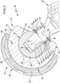
- a first embodiment of a hip joint endoprosthesis system 10 is shown schematically in Figure 1 It comprises a joint socket 10 and a joint head 14 corresponding to this to form a ball joint 16.
- the joint head 14 can be coupled to a femoral shaft 18, i.e. can be detachably connected.
- the hip joint endoprosthesis system 10 also includes the femoral shaft 18.
- the acetabulum 12 comprises an acetabular cup 20 which can be anchored in a patient's pelvis in a known manner.
- the acetabular shell 20 comprises an insert recess 22 into which an acetabular insert 24 is inserted.
- the acetabular shell 20 and the acetabular insert 24 are coupled to one another via a self-locking conical connection.
- the acetabular shell 20 has an inner conical surface 26 and the acetabular insert 24 has an outer conical surface 28 corresponding to the conical surface 26.
- the acetabular shell 20 and the acetabular insert 24 are made of a metallic material.
- both components can be made of titanium.
- the acetabular insert 24, which is received in the insert recess 22 of the acetabular shell 20, has a hollow spherical acetabular surface 30.
- the joint head 14 is made of two parts. It comprises a ball head 32 that can be coupled to the femoral shaft 18 and a joint head shell 34.
- the joint head shell 34 has a spherical outer surface 36 and a hollow spherical inner surface 38.
- the outer surface 36 and the inner surface 38 are concentric to each other and define a common joint center 40.
- the joint center 40 forms a center point of both the inner surface 38 and the outer surface 36.
- the joint head shell 34 is coupled to the joint socket insert 24 by a ball joint.
- joint head shell 34 the inner surface 38 of which is designed to correspond to a spherical ball head surface 42 of the ball head 32, is coupled to the ball head 32 in a ball-joint manner.
- the joint head shell 34 and the joint socket insert 24 form a first sliding pair. Furthermore, the joint head shell 34 and the joint head 32 form a second sliding pair.
- the joint head shell 34 is made of a plastic.
- the plastic is polyethylene.
- the joint head shell 34 is made of an ultra-high molecular weight polyethylene.
- the joint head 32 is made of a metallic material.
- the joint head 32 is made of an implant steel.
- a conical connection is used to couple the joint head 14 to the femoral shaft 18. This comprises an inner cone 44 defining a longitudinal axis 46 on the ball head 32.
- the joint center 40 lies on the longitudinal axis 46.
- the femoral shaft 18 comprises a femoral neck 48, on which a femoral cone 50 is formed.
- the femoral cone 50 forms a free end of the femoral neck 48.
- the femoral cone 50 is designed to correspond to the inner cone 44 and has a cone angle which, in conjunction with the inner cone 44, enables the formation of a self-locking cone connection between the ball head 32 and the femoral shaft 18.
- the ball head 32 can thus be secured in a rotationally fixed and axial manner to the femoral shaft 18 in a simple manner.
- the joint head shell 34 has a joint head shell stop surface 52 pointing in the direction of the longitudinal axis 46. This is conical and widens away from the joint head shell 34 in the direction of the femoral shaft 18.
- the ball head 32 comprises a protective element 54. It limits a movement of the joint head shell 34 in the direction of the femoral shaft 18 or in the direction of the longitudinal axis 46.
- the protective element 54 and the joint head are formed in one piece.
- the protective element 54 is designed as a sleeve-shaped enclosure surrounding the femoral shaft 18 in the region of the femoral neck 48.
- the protective element 54 which can also be referred to as the collar of the ball head 32 or as a protective sleeve, is from the femoral shaft 18, in particular from its femoral neck 48.
- an annular space 56 is formed between the protective element 54 and the femoral shaft 18.
- This annular space 56 is in the Figures 1 to 3 illustrated embodiment is opened in a direction pointing away from the ball head 32.
- the inner cone 44 defines an inner cone surface 58.
- the protective element 54 defines a protective element inner surface 60 pointing in the direction of the longitudinal axis 46.
- the protective element inner surface 60 is spaced from a conical extension surface 62 which virtually extends the inner cone surface 58.
- a distance 64 of the protective element 54 from the femoral shaft 18 is a maximum of 1 mm. Furthermore, a distance 66 of the extension surface 62 from the inner conical surface 58 is a maximum of 1 mm.
- the protective element inner surface 60 is set back slightly relative to the inner cone surface 48 with respect to the longitudinal axis 46. In order to achieve this, the inner cone 44 widens slightly in the inner diameter in a transition region 68 between the inner cone 44 and the protective element 54, in particular in one stage.
- a free end 70 of the protective element 54 pointing away from the ball head 32 is designed to be bead-shaped and thickened.
- the bead-shaped thickening points in particular away from the longitudinal axis 46 of the inner cone 44.
- the protective element 54 has a sleeve wall with a thickness 72.
- the thickness 72 is a maximum of 1 mm in the exemplary embodiment.
- the thickness 72 of the protective element 54 in the region of the end 70 can in particular be more than 1 mm. This is particularly possible and not disadvantageous, since the bead-shaped thickened end 70 does not limit a range of motion of the joint head shell 34 and the ball head 32 relative to each other.
- An outer surface 74 of the protective element 54 facing away from the longitudinal axis 46 is polished.
- the outer surface 74 has minimal, at most microscopic roughness and has neither corners nor edges.
- an outer contour of the joint head shell 34 is shaped in such a way that the joint head shell 34, when it is in contact with the protective element 54, touches the protective element 54 at least linearly, in particular flatly. This is achieved in the Figures 1 to 3 illustrated embodiment in that the outer contour of the joint head shell 34 includes the conical joint head shell stop surface 52.
- a cone angle of the joint head shell stop surface 52 is selected such that an intersection line of the same with a cutting plane containing the joint center 40 defines a first cutting line 76.
- a second cutting line 78 which is defined by the cutting plane intersecting the outer surface 74, runs parallel to the first cutting line 76 when the joint head shell stop surface 52 rests against the outer surface 74. This is shown schematically in Figure 3 shown.
- the ball-joint connection between the joint head shell 34 and the ball head 32 defines a first center of rotation. Furthermore, the ball-joint connection between the joint head shell 34 and the joint socket insert 24 defines a second center of rotation.
- the first and second centers of rotation are in the Figures 1 to 3 illustrated embodiment and coincide with the joint center 40.
- the hip joint endoprosthesis system 10 comprises several ball heads 32.
- ball heads 32a, 32b, 32c and 32d are shown as examples.
- Each of the ball heads 32a, 32b, 32c and 32d has an inner cone 44a, 44b, 44c and 44d respectively.
- the inner cones 44a, 44b, 44c and 44d are formed with different depths.
- a depth 80a, 80b, 80c or 80d of the inner cones 44a, 44b, 44c and 44d decreases successively from the ball head 32a to the ball head 32d. In this way, a position of the joint center 40 relative to the femoral shaft 18 can be varied. The further a free end 82 protrudes into the respective ball head 32a, 32b, 32c or 32d, the further away the joint center 40 is from the end 82.
- An outer diameter of 84 of the ball heads 32a, 32b, 32c and 32d is in the Figures 4 to 7 illustrated embodiments. This makes it possible to couple all ball heads 32, 32a, 32b, 32c and 32d with the same joint head shell 34 in a ball-joint manner.
- the joint head shell 34 defines an insertion opening which is limited in particular by the joint head shell stop surface 52. Its free cross-section is somewhat smaller than a cross-section of the ball heads 32, 32a, 32b, 32c and 32d which corresponds to the outer diameter 84. This makes it possible to snap the joint head shell 34 made of a plastic onto one of the ball heads 32, 32a, 32b, 32c or 32d.
- the cone connection between the ball head 32 and the femoral cone 50 defines a cone retention force.
- a protective element retention force is defined.
- a ratio of the protective element retention force and the cone retention force is in a range of about 1:20 to about 1:500. In an embodiment, this ratio is in a range of about 1:50 to about 1:200. In an embodiment, the ratio is about 1:100.
- a deformation force is required to deform the protective element 54 by striking the joint head shell 34.
- a deformation ratio of the deformation force and the holding force of the conical connection is in a range from approximately 1:20 to approximately 1:500. In one embodiment, the deformation ratio is in a range from approximately 1:50 to approximately 1:200. In another embodiment, the deformation ratio is approximately 1:100.
- hip joint endoprosthesis systems 10 make it possible in particular to use a femoral shaft 18 implanted in a patient in order to couple it to one of the described joint heads 14.
- the protective element 54 prevents direct contact between the joint head shell 34 and the femoral shaft 18, in particular its femoral neck 48.
- the special surface treatment of the outer surface 74 minimizes the risk of damage to the joint head shell 34, in particular in the area of its joint head shell stop surface 52.
Landscapes
- Health & Medical Sciences (AREA)
- Orthopedic Medicine & Surgery (AREA)
- Cardiology (AREA)
- Oral & Maxillofacial Surgery (AREA)
- Transplantation (AREA)
- Engineering & Computer Science (AREA)
- Biomedical Technology (AREA)
- Heart & Thoracic Surgery (AREA)
- Vascular Medicine (AREA)
- Life Sciences & Earth Sciences (AREA)
- Animal Behavior & Ethology (AREA)
- General Health & Medical Sciences (AREA)
- Public Health (AREA)
- Veterinary Medicine (AREA)
- Prostheses (AREA)
Claims (15)
- Système d'endoprothèse de la hanche (10) comprenant un cotyle (12) et un condyle (14), conçu de façon à correspondre au cotyle (12), pour la conception d'une articulation sphérique (16), lequel condyle (14) peut être couplé avec une tige fémorale (18), dans lequel le cotyle (12) présente une coque de cotyle (20) avec un évidement d'insert (22) dans lequel est inséré un insert de cotyle (24) avec une surface de cotyle (30) sphérique et creuse, dans lequel le condyle (14) est conçu en deux parties et comprend au moins une tête sphérique (32, 32a, 32b, 32c, 32d), qui peut être couplée avec la tige fémorale (18), et une coque de condyle (34) et dans lequel la coque de condyle (34) est couplée d'une part côté par articulation sphérique avec la au moins une tête sphérique (32, 32a, 32b, 32c, 32d) et d'autre part par articulation sphérique avec l'insert de cotyle (24), caractérisé en ce que la au moins une tête sphérique (32, 32a, 32b, 32c, 32d) comprend un élément de protection (54) pour limiter un mouvement de la coque de condyle (34) dans la direction de la tige fémorale (18).
- Système d'endoprothèse de la hanche selon la revendication 1, caractérisé en ce que l'élément de protection (54) et la au moins une tête sphérique (32, 32a, 32b, 32c, 32d) sont conçus en une seule pièce.
- Système d'endoprothèse de la hanche selon l'une des revendications précédentes, caractérisé en ce que la au moins une tête sphérique (32, 32a, 32b, 32c, 32d) présente un cône intérieur (44, 44a, 44b, 44c, 44d) pour la conception d'une liaison conique, en particulier autobloquante, avec un cône de fémur (50) correspondant de la tige fémorale (18).
- Système d'endoprothèse de la hanche selon la revendication 3, caractérisé en ce que l'élément de protection (54) enrobe sous forme de douille la tige fémorale (18).
- Système d'endoprothèse de la hanche selon la revendication 3 ou 4, caractérisé en ce que l'élément de protection (54) est agencé à distance de la tige fémorale (18), en particulier d'un col de fémur (48) de celle-ci, pour la conception d'un espace annulaire (56) entre l'élément de protection (54) et la tige fémorale (18).
- Système d'endoprothèse de la hanche selon l'une des revendications 3 à 5, caractérisé en ce que le cône intérieur (44, 44a, 44b, 44c, 44d) définit une surface de cône intérieur (58) et en ce qu'une surface intérieure d'élément de protection (60), orientée en direction de la tige fémorale, de l'élément de protection (54) est à distance d'une surface de prolongement prolongeant virtuellement la surface de cône intérieur (58).
- Système d'endoprothèse de la hanche selon la revendication 5 ou 6, caractérisé en ce qu'une distance (64) de l'élément de protection (54) par rapport à la tige fémorale (18) et/ou une distance (66) de la surface de prolongement virtuelle (62) par rapport à la surface de cône intérieur (58) est au maximum de 1 mm.
- Système d'endoprothèse de la hanche selon l'une des revendications 3 à 7, caractérisé en ce que le cône intérieur (44, 44a, 44b, 44c, 44d) s'élargit en diamètre intérieur, en particulier en une étape, dans la zone de transition vers l'élément de protection (54).
- Système d'endoprothèse de la hanche selon l'une des revendications précédentes, caractérisé en ce quea) une extrémité (70) libre, orientée en s'éloignant de la au moins une tête sphérique (32, 32a, 32b, 32c, 32d), de l'élément de protection (54) est conçue de façon épaissie en forme de boudin, en particulier orientée en s'éloignant d'un axe longitudinal (46) du cône intérieur (44),
et/oub) une surface extérieure (74), orientée en s'éloignant de la tige fémorale (18), de l'élément de protection (54) est polie
et/ouc) l'élément de protection (54) présente une épaisseur (72) qui est au maximum de 1 mm. - Système d'endoprothèse de la hanche selon l'une des revendications précédentes, caractérisé en ce quea) la au moins une tête sphérique (32, 32a, 32b, 32c, 32d) est conçue dans un matériau métallique
et/oub) la coque de condyle (34) est conçue dans un matériau, en particulier dans un polyéthylène, davantage en particulier dans un polyéthylène à poids moléculaire ultra élevé (UHMWPE). - Système d'endoprothèse de la hanche selon l'une des revendications précédentes, caractérisé en ce qu'un contour extérieur de la coque de condyle (34) est façonné de sorte que, lorsqu'il est en contact avec l'élément de protection (54), il effleure l'élément de protection (54) au moins sous la forme d'une ligne, en particulier en surface,
dans lequel en particulier le contour extérieur de la coque de condyle (34) présente une surface de butée de coque de condyle (52) conique, orientée en direction du col de fémur (48), et en ce qu'une première intersection (76) de la surface de butée de coque de condyle (52) avec un plan de coupe dans lequel un centre d'articulation (40) de la liaison par articulation sphérique se situe entre la coque de condyle (34) et la au moins une tête sphérique (32, 32a, 32b, 32c, 32d), se déroule en parallèle ou sensiblement en parallèle d'une deuxième intersection (78) de l'élément de protection (54) avec le plan de coupe. - Système d'endoprothèse de la hanche selon l'une des revendications 3 à 11, caractérisé en ce que le système d'endoprothèse de la hanche (10) comprend deux ou plusieurs têtes sphériques (32, 32a, 32b, 32c, 32d) et en ce que des cônes intérieurs (44, 44a, 44b, 44c, 44d) des deux ou plusieurs têtes sphériques (32, 32a, 32b, 32c, 32d) sont conçus avec des profondeurs différentes,
dans lequel en particulier un diamètre extérieur (84) défini par les deux ou plusieurs têtes sphériques (32, 32a, 32b, 32c, 32d) est identique ou sensiblement identique. - Système d'endoprothèse de la hanche selon l'une des revendications précédentes, caractérisé en ce que la liaison par articulation sphérique définit un premier centre de rotation (40) entre la coque de condyle (34) et la au moins une tête sphérique (32, 32a, 32b, 32c, 32d), en ce que la liaison par articulation sphérique définit un deuxième centre de rotation (40) entre la coque de condyle (34) et l'insert de cotyle (24) et en ce que le premier centre de rotation (40) et le deuxième centre de rotation (40) sont identiques ou sensiblement identiques.
- Système d'endoprothèse de la hanche selon l'une des revendications précédentes, caractérisé par une tige fémorale (18) avec un col de fémur (48) au niveau duquel est conçu un cône de fémur (50), lequel cône de fémur (50) forme une extrémité libre du col de fémur (48).
- Système d'endoprothèse de la hanche selon la revendication 14, caractérisé en ce quea) un rapport d'une force de retenue d'élément de protection entre l'élément de protection (54) et le cône de fémur (50) et/ou le col de fémur (48) d'une part à une force de retenue de cône de la liaison conique d'autre part se situe dans une plage allant d'environ 1/20 à environ 1/500, en particulier dans une plage allant d'environ 1/50 à environ 1/200, davantage en particulier est d'environ 1/100,
et/oub) un rapport de déformation d'une force de déformation pour déformer l'élément de protection (54) par frappe de la coque de condyle (34) d'une part à une force de retenue de la liaison conique d'autre part se situe dans une plage allant d'environ 1/20 à environ 1/500, en particulier dans une plage allant d'environ 1/50 à environ 1/200, davantage en particulier est d'environ 1/100.
Applications Claiming Priority (1)
| Application Number | Priority Date | Filing Date | Title |
|---|---|---|---|
| DE102019107244.1A DE102019107244A1 (de) | 2019-03-21 | 2019-03-21 | Hüftgelenkendoprothesensystem |
Publications (3)
| Publication Number | Publication Date |
|---|---|
| EP3721837A1 EP3721837A1 (fr) | 2020-10-14 |
| EP3721837A3 EP3721837A3 (fr) | 2020-12-02 |
| EP3721837B1 true EP3721837B1 (fr) | 2024-10-23 |
Family
ID=70108026
Family Applications (1)
| Application Number | Title | Priority Date | Filing Date |
|---|---|---|---|
| EP20164509.0A Active EP3721837B1 (fr) | 2019-03-21 | 2020-03-20 | Système d'endoprothèse d'articulation de la hanche |
Country Status (2)
| Country | Link |
|---|---|
| EP (1) | EP3721837B1 (fr) |
| DE (1) | DE102019107244A1 (fr) |
Families Citing this family (2)
| Publication number | Priority date | Publication date | Assignee | Title |
|---|---|---|---|---|
| EP4281015B1 (fr) * | 2021-01-19 | 2025-04-02 | Smith & Nephew, Inc. | Implant acétabulaire à double mobilité pour la chirurgie de révision de la hanche |
| WO2026068966A1 (fr) * | 2024-09-30 | 2026-04-02 | Midland Medical Technology Ltd | Tête et col prothétique et composants de tige destinés à être utilisés dans une arthroplastie de la hanche |
Family Cites Families (6)
| Publication number | Priority date | Publication date | Assignee | Title |
|---|---|---|---|---|
| US4678472A (en) * | 1983-03-08 | 1987-07-07 | Joint Medical Products Corporation | Ball and socket bearing for artificial joint |
| CH675822A5 (fr) * | 1988-09-06 | 1990-11-15 | Sulzer Ag | |
| US6761741B2 (en) * | 2002-06-10 | 2004-07-13 | Kazuho Iesaka | Prosthetic joint |
| US20060217815A1 (en) * | 2002-09-24 | 2006-09-28 | Biomet Manufacturing Corp | Modular prosthetic head having a flat portion to be implanted into a constrained liner |
| DE102005028523A1 (de) * | 2005-05-19 | 2006-11-23 | Plus Orthopedics Ag | Gelenkpfanne für eine Hüftgelenkendoprothese, Prothese mit einer derartigen Gelenkpfanne und Protheseset |
| CN105263447A (zh) * | 2012-09-27 | 2016-01-20 | 马萨诸塞总医院运营总医院公司 | 用于整形外科植入物的股骨头、移动插件、髋臼部件和模块式接合部以及使用用于整形外科植入物的股骨头、移动插件、髋臼部件和模块式接合部的方法 |
-
2019
- 2019-03-21 DE DE102019107244.1A patent/DE102019107244A1/de not_active Withdrawn
-
2020
- 2020-03-20 EP EP20164509.0A patent/EP3721837B1/fr active Active
Also Published As
| Publication number | Publication date |
|---|---|
| EP3721837A3 (fr) | 2020-12-02 |
| EP3721837A1 (fr) | 2020-10-14 |
| DE102019107244A1 (de) | 2020-09-24 |
Similar Documents
| Publication | Publication Date | Title |
|---|---|---|
| EP0583711B1 (fr) | Endoprothèse à tête sphérique | |
| DE69001139T2 (de) | Hueftgelenkspfanne mit zwei radien. | |
| DE69822266T2 (de) | Modulare Ellenbogenprothese | |
| EP0388745B1 (fr) | Cuvette d'articulation de la hanche pour l'implantation sans ciment dans la cavité acétabulaire | |
| DE69921526T2 (de) | Bipolare Hüftprothese mit Verriegelungskopf | |
| DE69225472T2 (de) | Längliche hüftpfannenschale | |
| DE602004008018T2 (de) | Schulter- oder Hüftprothese und ihr Montageverfahren | |
| EP0808619B1 (fr) | Endoprothèse de l'articulation du coude | |
| EP0315795B1 (fr) | Cotyle | |
| DE69331586T2 (de) | Verbessertes femorales manschettenimplantat | |
| DE69005090T2 (de) | Pfanneprothese-Verbindung. | |
| DE69419540T2 (de) | Einstellbares Prothesenpfannenteil für anatomische Gelenke | |
| EP1924208B1 (fr) | Implant du femur | |
| DE69715264T2 (de) | Knochenprothese | |
| EP0187903B1 (fr) | Prothèse d'articulation de la hanche | |
| DE8304914U1 (de) | Kugelförmiges kinematisches Gelenk | |
| DE9301107U1 (de) | Oberschenkelknochenkomponente zur Verwendung in einem Hüftgelenkersatz | |
| DE69114050T2 (de) | Kugelgelenk für Prothese. | |
| DE10360390B4 (de) | Gelenkpfanne für eine Hüftendoprothese | |
| EP3721837B1 (fr) | Système d'endoprothèse d'articulation de la hanche | |
| EP0774937A1 (fr) | Articulation artificielle, utile notamment pour remplacer l'articulation de la hanche humaine | |
| EP3714840B1 (fr) | Cavité cotyloïde d'une endoprothèse de l'articulation de la hanche | |
| EP0119321A1 (fr) | Cuvette pour l'articulation de la hanche | |
| EP3386441B1 (fr) | Implant d'articulation artificielle et endoprothèse de la hanche | |
| EP1885294B1 (fr) | Prothese du col du femur |
Legal Events
| Date | Code | Title | Description |
|---|---|---|---|
| PUAI | Public reference made under article 153(3) epc to a published international application that has entered the european phase |
Free format text: ORIGINAL CODE: 0009012 |
|
| STAA | Information on the status of an ep patent application or granted ep patent |
Free format text: STATUS: THE APPLICATION HAS BEEN PUBLISHED |
|
| PUAB | Information related to the publication of an a document modified or deleted |
Free format text: ORIGINAL CODE: 0009199EPPU |
|
| PUAI | Public reference made under article 153(3) epc to a published international application that has entered the european phase |
Free format text: ORIGINAL CODE: 0009012 |
|
| PUAB | Information related to the publication of an a document modified or deleted |
Free format text: ORIGINAL CODE: 0009199EPPU |
|
| PUAF | Information related to the publication of a search report (a3 document) modified or deleted |
Free format text: ORIGINAL CODE: 0009199SEPU |
|
| AK | Designated contracting states |
Kind code of ref document: A1 Designated state(s): AL AT BE BG CH CY CZ DE DK EE ES FI FR GB GR HR HU IE IS IT LI LT LU LV MC MK MT NL NO PL PT RO RS SE SI SK SM TR |
|
| AX | Request for extension of the european patent |
Extension state: BA ME |
|
| RIC1 | Information provided on ipc code assigned before grant |
Ipc: A61F 2/36 20060101ALN20200918BHEP Ipc: A61F 2/32 20060101AFI20200918BHEP |
|
| PUAL | Search report despatched |
Free format text: ORIGINAL CODE: 0009013 |
|
| D17D | Deferred search report published (deleted) | ||
| AK | Designated contracting states |
Kind code of ref document: A3 Designated state(s): AL AT BE BG CH CY CZ DE DK EE ES FI FR GB GR HR HU IE IS IT LI LT LU LV MC MK MT NL NO PL PT RO RS SE SI SK SM TR |
|
| AX | Request for extension of the european patent |
Extension state: BA ME |
|
| STAA | Information on the status of an ep patent application or granted ep patent |
Free format text: STATUS: REQUEST FOR EXAMINATION WAS MADE |
|
| 17P | Request for examination filed |
Effective date: 20210304 |
|
| RBV | Designated contracting states (corrected) |
Designated state(s): AL AT BE BG CH CY CZ DE DK EE ES FI FR GB GR HR HU IE IS IT LI LT LU LV MC MK MT NL NO PL PT RO RS SE SI SK SM TR |
|
| GRAP | Despatch of communication of intention to grant a patent |
Free format text: ORIGINAL CODE: EPIDOSNIGR1 |
|
| STAA | Information on the status of an ep patent application or granted ep patent |
Free format text: STATUS: GRANT OF PATENT IS INTENDED |
|
| RIC1 | Information provided on ipc code assigned before grant |
Ipc: A61F 2/36 20060101ALN20240228BHEP Ipc: A61F 2/32 20060101AFI20240228BHEP |
|
| INTG | Intention to grant announced |
Effective date: 20240319 |
|
| GRAJ | Information related to disapproval of communication of intention to grant by the applicant or resumption of examination proceedings by the epo deleted |
Free format text: ORIGINAL CODE: EPIDOSDIGR1 |
|
| STAA | Information on the status of an ep patent application or granted ep patent |
Free format text: STATUS: REQUEST FOR EXAMINATION WAS MADE |
|
| INTC | Intention to grant announced (deleted) | ||
| GRAP | Despatch of communication of intention to grant a patent |
Free format text: ORIGINAL CODE: EPIDOSNIGR1 |
|
| STAA | Information on the status of an ep patent application or granted ep patent |
Free format text: STATUS: GRANT OF PATENT IS INTENDED |
|
| RIC1 | Information provided on ipc code assigned before grant |
Ipc: A61F 2/36 20060101ALN20240730BHEP Ipc: A61F 2/32 20060101AFI20240730BHEP |
|
| INTG | Intention to grant announced |
Effective date: 20240813 |
|
| GRAS | Grant fee paid |
Free format text: ORIGINAL CODE: EPIDOSNIGR3 |
|
| GRAA | (expected) grant |
Free format text: ORIGINAL CODE: 0009210 |
|
| STAA | Information on the status of an ep patent application or granted ep patent |
Free format text: STATUS: THE PATENT HAS BEEN GRANTED |
|
| AK | Designated contracting states |
Kind code of ref document: B1 Designated state(s): AL AT BE BG CH CY CZ DE DK EE ES FI FR GB GR HR HU IE IS IT LI LT LU LV MC MK MT NL NO PL PT RO RS SE SI SK SM TR |
|
| REG | Reference to a national code |
Ref country code: GB Ref legal event code: FG4D Free format text: NOT ENGLISH |
|
| REG | Reference to a national code |
Ref country code: CH Ref legal event code: EP |
|
| REG | Reference to a national code |
Ref country code: DE Ref legal event code: R096 Ref document number: 502020009539 Country of ref document: DE |
|
| REG | Reference to a national code |
Ref country code: IE Ref legal event code: FG4D Free format text: LANGUAGE OF EP DOCUMENT: GERMAN |
|
| P01 | Opt-out of the competence of the unified patent court (upc) registered |
Free format text: CASE NUMBER: APP_59262/2024 Effective date: 20241031 |
|
| REG | Reference to a national code |
Ref country code: LT Ref legal event code: MG9D |
|
| REG | Reference to a national code |
Ref country code: NL Ref legal event code: MP Effective date: 20241023 |
|
| PG25 | Lapsed in a contracting state [announced via postgrant information from national office to epo] |
Ref country code: NL Free format text: LAPSE BECAUSE OF FAILURE TO SUBMIT A TRANSLATION OF THE DESCRIPTION OR TO PAY THE FEE WITHIN THE PRESCRIBED TIME-LIMIT Effective date: 20241023 |
|
| PG25 | Lapsed in a contracting state [announced via postgrant information from national office to epo] |
Ref country code: NL Free format text: LAPSE BECAUSE OF FAILURE TO SUBMIT A TRANSLATION OF THE DESCRIPTION OR TO PAY THE FEE WITHIN THE PRESCRIBED TIME-LIMIT Effective date: 20241023 |
|
| PG25 | Lapsed in a contracting state [announced via postgrant information from national office to epo] |
Ref country code: HR Free format text: LAPSE BECAUSE OF FAILURE TO SUBMIT A TRANSLATION OF THE DESCRIPTION OR TO PAY THE FEE WITHIN THE PRESCRIBED TIME-LIMIT Effective date: 20241023 Ref country code: PT Free format text: LAPSE BECAUSE OF FAILURE TO SUBMIT A TRANSLATION OF THE DESCRIPTION OR TO PAY THE FEE WITHIN THE PRESCRIBED TIME-LIMIT Effective date: 20250224 Ref country code: IS Free format text: LAPSE BECAUSE OF FAILURE TO SUBMIT A TRANSLATION OF THE DESCRIPTION OR TO PAY THE FEE WITHIN THE PRESCRIBED TIME-LIMIT Effective date: 20250223 |
|
| PG25 | Lapsed in a contracting state [announced via postgrant information from national office to epo] |
Ref country code: FI Free format text: LAPSE BECAUSE OF FAILURE TO SUBMIT A TRANSLATION OF THE DESCRIPTION OR TO PAY THE FEE WITHIN THE PRESCRIBED TIME-LIMIT Effective date: 20241023 |
|
| PG25 | Lapsed in a contracting state [announced via postgrant information from national office to epo] |
Ref country code: BG Free format text: LAPSE BECAUSE OF FAILURE TO SUBMIT A TRANSLATION OF THE DESCRIPTION OR TO PAY THE FEE WITHIN THE PRESCRIBED TIME-LIMIT Effective date: 20241023 |
|
| PG25 | Lapsed in a contracting state [announced via postgrant information from national office to epo] |
Ref country code: ES Free format text: LAPSE BECAUSE OF FAILURE TO SUBMIT A TRANSLATION OF THE DESCRIPTION OR TO PAY THE FEE WITHIN THE PRESCRIBED TIME-LIMIT Effective date: 20241023 |
|
| PG25 | Lapsed in a contracting state [announced via postgrant information from national office to epo] |
Ref country code: NO Free format text: LAPSE BECAUSE OF FAILURE TO SUBMIT A TRANSLATION OF THE DESCRIPTION OR TO PAY THE FEE WITHIN THE PRESCRIBED TIME-LIMIT Effective date: 20250123 |
|
| PG25 | Lapsed in a contracting state [announced via postgrant information from national office to epo] |
Ref country code: LV Free format text: LAPSE BECAUSE OF FAILURE TO SUBMIT A TRANSLATION OF THE DESCRIPTION OR TO PAY THE FEE WITHIN THE PRESCRIBED TIME-LIMIT Effective date: 20241023 Ref country code: GR Free format text: LAPSE BECAUSE OF FAILURE TO SUBMIT A TRANSLATION OF THE DESCRIPTION OR TO PAY THE FEE WITHIN THE PRESCRIBED TIME-LIMIT Effective date: 20250124 |
|
| PG25 | Lapsed in a contracting state [announced via postgrant information from national office to epo] |
Ref country code: PL Free format text: LAPSE BECAUSE OF FAILURE TO SUBMIT A TRANSLATION OF THE DESCRIPTION OR TO PAY THE FEE WITHIN THE PRESCRIBED TIME-LIMIT Effective date: 20241023 |
|
| PG25 | Lapsed in a contracting state [announced via postgrant information from national office to epo] |
Ref country code: RS Free format text: LAPSE BECAUSE OF FAILURE TO SUBMIT A TRANSLATION OF THE DESCRIPTION OR TO PAY THE FEE WITHIN THE PRESCRIBED TIME-LIMIT Effective date: 20250123 |
|
| PG25 | Lapsed in a contracting state [announced via postgrant information from national office to epo] |
Ref country code: SM Free format text: LAPSE BECAUSE OF FAILURE TO SUBMIT A TRANSLATION OF THE DESCRIPTION OR TO PAY THE FEE WITHIN THE PRESCRIBED TIME-LIMIT Effective date: 20241023 |
|
| PG25 | Lapsed in a contracting state [announced via postgrant information from national office to epo] |
Ref country code: DK Free format text: LAPSE BECAUSE OF FAILURE TO SUBMIT A TRANSLATION OF THE DESCRIPTION OR TO PAY THE FEE WITHIN THE PRESCRIBED TIME-LIMIT Effective date: 20241023 |
|
| PG25 | Lapsed in a contracting state [announced via postgrant information from national office to epo] |
Ref country code: EE Free format text: LAPSE BECAUSE OF FAILURE TO SUBMIT A TRANSLATION OF THE DESCRIPTION OR TO PAY THE FEE WITHIN THE PRESCRIBED TIME-LIMIT Effective date: 20241023 |
|
| PGFP | Annual fee paid to national office [announced via postgrant information from national office to epo] |
Ref country code: CH Payment date: 20250401 Year of fee payment: 6 |
|
| PG25 | Lapsed in a contracting state [announced via postgrant information from national office to epo] |
Ref country code: RO Free format text: LAPSE BECAUSE OF FAILURE TO SUBMIT A TRANSLATION OF THE DESCRIPTION OR TO PAY THE FEE WITHIN THE PRESCRIBED TIME-LIMIT Effective date: 20241023 |
|
| REG | Reference to a national code |
Ref country code: DE Ref legal event code: R097 Ref document number: 502020009539 Country of ref document: DE |
|
| PG25 | Lapsed in a contracting state [announced via postgrant information from national office to epo] |
Ref country code: SK Free format text: LAPSE BECAUSE OF FAILURE TO SUBMIT A TRANSLATION OF THE DESCRIPTION OR TO PAY THE FEE WITHIN THE PRESCRIBED TIME-LIMIT Effective date: 20241023 |
|
| PG25 | Lapsed in a contracting state [announced via postgrant information from national office to epo] |
Ref country code: CZ Free format text: LAPSE BECAUSE OF FAILURE TO SUBMIT A TRANSLATION OF THE DESCRIPTION OR TO PAY THE FEE WITHIN THE PRESCRIBED TIME-LIMIT Effective date: 20241023 |
|
| PG25 | Lapsed in a contracting state [announced via postgrant information from national office to epo] |
Ref country code: IT Free format text: LAPSE BECAUSE OF FAILURE TO SUBMIT A TRANSLATION OF THE DESCRIPTION OR TO PAY THE FEE WITHIN THE PRESCRIBED TIME-LIMIT Effective date: 20241023 |
|
| PLBE | No opposition filed within time limit |
Free format text: ORIGINAL CODE: 0009261 |
|
| STAA | Information on the status of an ep patent application or granted ep patent |
Free format text: STATUS: NO OPPOSITION FILED WITHIN TIME LIMIT |
|
| PG25 | Lapsed in a contracting state [announced via postgrant information from national office to epo] |
Ref country code: SE Free format text: LAPSE BECAUSE OF FAILURE TO SUBMIT A TRANSLATION OF THE DESCRIPTION OR TO PAY THE FEE WITHIN THE PRESCRIBED TIME-LIMIT Effective date: 20241023 |
|
| 26N | No opposition filed |
Effective date: 20250724 |
|
| PG25 | Lapsed in a contracting state [announced via postgrant information from national office to epo] |
Ref country code: MC Free format text: LAPSE BECAUSE OF FAILURE TO SUBMIT A TRANSLATION OF THE DESCRIPTION OR TO PAY THE FEE WITHIN THE PRESCRIBED TIME-LIMIT Effective date: 20241023 |
|
| PG25 | Lapsed in a contracting state [announced via postgrant information from national office to epo] |
Ref country code: LU Free format text: LAPSE BECAUSE OF NON-PAYMENT OF DUE FEES Effective date: 20250320 |
|
| REG | Reference to a national code |
Ref country code: BE Ref legal event code: MM Effective date: 20250331 |
|
| PG25 | Lapsed in a contracting state [announced via postgrant information from national office to epo] |
Ref country code: BE Free format text: LAPSE BECAUSE OF NON-PAYMENT OF DUE FEES Effective date: 20250331 |
|
| REG | Reference to a national code |
Ref country code: CH Ref legal event code: U11 Free format text: ST27 STATUS EVENT CODE: U-0-0-U10-U11 (AS PROVIDED BY THE NATIONAL OFFICE) Effective date: 20260401 |
|
| PGFP | Annual fee paid to national office [announced via postgrant information from national office to epo] |
Ref country code: GB Payment date: 20260324 Year of fee payment: 7 |
|
| PGFP | Annual fee paid to national office [announced via postgrant information from national office to epo] |
Ref country code: DE Payment date: 20260320 Year of fee payment: 7 Ref country code: IE Payment date: 20260323 Year of fee payment: 7 |
|
| PGFP | Annual fee paid to national office [announced via postgrant information from national office to epo] |
Ref country code: FR Payment date: 20260325 Year of fee payment: 7 |