EP3721840A1 - Orthèse de pouce et ensemble pourvu d'une pluralité d'orthèses - Google Patents
Orthèse de pouce et ensemble pourvu d'une pluralité d'orthèses Download PDFInfo
- Publication number
- EP3721840A1 EP3721840A1 EP19169043.7A EP19169043A EP3721840A1 EP 3721840 A1 EP3721840 A1 EP 3721840A1 EP 19169043 A EP19169043 A EP 19169043A EP 3721840 A1 EP3721840 A1 EP 3721840A1
- Authority
- EP
- European Patent Office
- Prior art keywords
- thumb
- expansion body
- orthosis
- index finger
- holding
- Prior art date
- Legal status (The legal status is an assumption and is not a legal conclusion. Google has not performed a legal analysis and makes no representation as to the accuracy of the status listed.)
- Withdrawn
Links
- 210000003813 thumb Anatomy 0.000 title claims abstract description 216
- 210000003811 finger Anatomy 0.000 claims abstract description 71
- 230000008878 coupling Effects 0.000 claims description 18
- 238000010168 coupling process Methods 0.000 claims description 18
- 238000005859 coupling reaction Methods 0.000 claims description 18
- 210000003414 extremity Anatomy 0.000 claims description 18
- 230000002829 reductive effect Effects 0.000 claims description 10
- 239000004033 plastic Substances 0.000 claims description 9
- 229920003023 plastic Polymers 0.000 claims description 9
- 238000000926 separation method Methods 0.000 claims description 9
- 210000004247 hand Anatomy 0.000 claims description 6
- 210000002414 leg Anatomy 0.000 description 59
- 235000001674 Agaricus brunnescens Nutrition 0.000 description 12
- 210000005224 forefinger Anatomy 0.000 description 7
- 239000000463 material Substances 0.000 description 7
- 230000008859 change Effects 0.000 description 5
- 229910052751 metal Inorganic materials 0.000 description 5
- 239000002184 metal Substances 0.000 description 5
- 230000005489 elastic deformation Effects 0.000 description 3
- 230000009021 linear effect Effects 0.000 description 3
- 239000004753 textile Substances 0.000 description 3
- 230000007704 transition Effects 0.000 description 3
- 210000000707 wrist Anatomy 0.000 description 3
- 208000006115 C. S. Lewis type symphalangism Diseases 0.000 description 2
- 230000006978 adaptation Effects 0.000 description 2
- 239000002131 composite material Substances 0.000 description 2
- 238000005520 cutting process Methods 0.000 description 2
- 230000006378 damage Effects 0.000 description 2
- 230000000694 effects Effects 0.000 description 2
- 229920001971 elastomer Polymers 0.000 description 2
- 238000001746 injection moulding Methods 0.000 description 2
- 201000008482 osteoarthritis Diseases 0.000 description 2
- 230000009467 reduction Effects 0.000 description 2
- 239000000243 solution Substances 0.000 description 2
- 210000000689 upper leg Anatomy 0.000 description 2
- 230000000007 visual effect Effects 0.000 description 2
- 230000003313 weakening effect Effects 0.000 description 2
- MMICQXASNBCNBA-UHFFFAOYSA-N CC(C)(CCCN)CC1CC1 Chemical compound CC(C)(CCCN)CC1CC1 MMICQXASNBCNBA-UHFFFAOYSA-N 0.000 description 1
- 206010065433 Ligament rupture Diseases 0.000 description 1
- 239000004433 Thermoplastic polyurethane Substances 0.000 description 1
- 208000027418 Wounds and injury Diseases 0.000 description 1
- 230000009471 action Effects 0.000 description 1
- 238000004026 adhesive bonding Methods 0.000 description 1
- AZDRQVAHHNSJOQ-UHFFFAOYSA-N alumane Chemical group [AlH3] AZDRQVAHHNSJOQ-UHFFFAOYSA-N 0.000 description 1
- 229910052782 aluminium Inorganic materials 0.000 description 1
- XAGFODPZIPBFFR-UHFFFAOYSA-N aluminium Chemical compound [Al] XAGFODPZIPBFFR-UHFFFAOYSA-N 0.000 description 1
- 238000005452 bending Methods 0.000 description 1
- 210000000511 carpometacarpal joint Anatomy 0.000 description 1
- 210000000845 cartilage Anatomy 0.000 description 1
- 230000001684 chronic effect Effects 0.000 description 1
- 210000004439 collateral ligament Anatomy 0.000 description 1
- 238000010276 construction Methods 0.000 description 1
- 230000007423 decrease Effects 0.000 description 1
- 230000006735 deficit Effects 0.000 description 1
- 230000003412 degenerative effect Effects 0.000 description 1
- 230000001419 dependent effect Effects 0.000 description 1
- 238000011161 development Methods 0.000 description 1
- 230000018109 developmental process Effects 0.000 description 1
- 238000006073 displacement reaction Methods 0.000 description 1
- 239000006260 foam Substances 0.000 description 1
- 238000010438 heat treatment Methods 0.000 description 1
- 230000001771 impaired effect Effects 0.000 description 1
- 208000014674 injury Diseases 0.000 description 1
- 230000003993 interaction Effects 0.000 description 1
- 230000007794 irritation Effects 0.000 description 1
- 239000002655 kraft paper Substances 0.000 description 1
- 230000000670 limiting effect Effects 0.000 description 1
- 210000004932 little finger Anatomy 0.000 description 1
- 238000004519 manufacturing process Methods 0.000 description 1
- 210000000811 metacarpophalangeal joint Anatomy 0.000 description 1
- 239000000203 mixture Substances 0.000 description 1
- 230000000399 orthopedic effect Effects 0.000 description 1
- 230000036961 partial effect Effects 0.000 description 1
- 230000001575 pathological effect Effects 0.000 description 1
- 229920001296 polysiloxane Polymers 0.000 description 1
- 229920002635 polyurethane Polymers 0.000 description 1
- 239000004814 polyurethane Substances 0.000 description 1
- 230000002980 postoperative effect Effects 0.000 description 1
- 238000003825 pressing Methods 0.000 description 1
- 230000003449 preventive effect Effects 0.000 description 1
- 238000009958 sewing Methods 0.000 description 1
- 230000007480 spreading Effects 0.000 description 1
- 238000003892 spreading Methods 0.000 description 1
- 230000001225 therapeutic effect Effects 0.000 description 1
- 238000002560 therapeutic procedure Methods 0.000 description 1
- 229920002725 thermoplastic elastomer Polymers 0.000 description 1
- 239000012815 thermoplastic material Substances 0.000 description 1
- 229920002803 thermoplastic polyurethane Polymers 0.000 description 1
Images





Classifications
-
- A—HUMAN NECESSITIES
- A61—MEDICAL OR VETERINARY SCIENCE; HYGIENE
- A61F—FILTERS IMPLANTABLE INTO BLOOD VESSELS; PROSTHESES; DEVICES PROVIDING PATENCY TO, OR PREVENTING COLLAPSING OF, TUBULAR STRUCTURES OF THE BODY, e.g. STENTS; ORTHOPAEDIC, NURSING OR CONTRACEPTIVE DEVICES; FOMENTATION; TREATMENT OR PROTECTION OF EYES OR EARS; BANDAGES, DRESSINGS OR ABSORBENT PADS; FIRST-AID KITS
- A61F5/00—Orthopaedic methods or devices for non-surgical treatment of bones or joints; Nursing devices ; Anti-rape devices
- A61F5/01—Orthopaedic devices, e.g. long-term immobilising or pressure directing devices for treating broken or deformed bones such as splints, casts or braces
- A61F5/0102—Orthopaedic devices, e.g. long-term immobilising or pressure directing devices for treating broken or deformed bones such as splints, casts or braces specially adapted for correcting deformities of the limbs or for supporting them; Ortheses, e.g. with articulations
- A61F5/0104—Orthopaedic devices, e.g. long-term immobilising or pressure directing devices for treating broken or deformed bones such as splints, casts or braces specially adapted for correcting deformities of the limbs or for supporting them; Ortheses, e.g. with articulations without articulation
- A61F5/0118—Orthopaedic devices, e.g. long-term immobilising or pressure directing devices for treating broken or deformed bones such as splints, casts or braces specially adapted for correcting deformities of the limbs or for supporting them; Ortheses, e.g. with articulations without articulation for the arms, hands or fingers
-
- A—HUMAN NECESSITIES
- A61—MEDICAL OR VETERINARY SCIENCE; HYGIENE
- A61F—FILTERS IMPLANTABLE INTO BLOOD VESSELS; PROSTHESES; DEVICES PROVIDING PATENCY TO, OR PREVENTING COLLAPSING OF, TUBULAR STRUCTURES OF THE BODY, e.g. STENTS; ORTHOPAEDIC, NURSING OR CONTRACEPTIVE DEVICES; FOMENTATION; TREATMENT OR PROTECTION OF EYES OR EARS; BANDAGES, DRESSINGS OR ABSORBENT PADS; FIRST-AID KITS
- A61F5/00—Orthopaedic methods or devices for non-surgical treatment of bones or joints; Nursing devices ; Anti-rape devices
- A61F5/01—Orthopaedic devices, e.g. long-term immobilising or pressure directing devices for treating broken or deformed bones such as splints, casts or braces
- A61F5/04—Devices for stretching or reducing fractured limbs; Devices for distractions; Splints
- A61F5/05—Devices for stretching or reducing fractured limbs; Devices for distractions; Splints for immobilising
- A61F5/058—Splints
- A61F5/05841—Splints for the limbs
- A61F5/05858—Splints for the limbs for the arms
- A61F5/05866—Splints for the limbs for the arms for wrists, hands, fingers or thumbs
-
- A—HUMAN NECESSITIES
- A61—MEDICAL OR VETERINARY SCIENCE; HYGIENE
- A61F—FILTERS IMPLANTABLE INTO BLOOD VESSELS; PROSTHESES; DEVICES PROVIDING PATENCY TO, OR PREVENTING COLLAPSING OF, TUBULAR STRUCTURES OF THE BODY, e.g. STENTS; ORTHOPAEDIC, NURSING OR CONTRACEPTIVE DEVICES; FOMENTATION; TREATMENT OR PROTECTION OF EYES OR EARS; BANDAGES, DRESSINGS OR ABSORBENT PADS; FIRST-AID KITS
- A61F5/00—Orthopaedic methods or devices for non-surgical treatment of bones or joints; Nursing devices ; Anti-rape devices
- A61F5/01—Orthopaedic devices, e.g. long-term immobilising or pressure directing devices for treating broken or deformed bones such as splints, casts or braces
- A61F5/10—Devices for correcting deformities of the fingers
-
- A—HUMAN NECESSITIES
- A61—MEDICAL OR VETERINARY SCIENCE; HYGIENE
- A61F—FILTERS IMPLANTABLE INTO BLOOD VESSELS; PROSTHESES; DEVICES PROVIDING PATENCY TO, OR PREVENTING COLLAPSING OF, TUBULAR STRUCTURES OF THE BODY, e.g. STENTS; ORTHOPAEDIC, NURSING OR CONTRACEPTIVE DEVICES; FOMENTATION; TREATMENT OR PROTECTION OF EYES OR EARS; BANDAGES, DRESSINGS OR ABSORBENT PADS; FIRST-AID KITS
- A61F5/00—Orthopaedic methods or devices for non-surgical treatment of bones or joints; Nursing devices ; Anti-rape devices
- A61F5/01—Orthopaedic devices, e.g. long-term immobilising or pressure directing devices for treating broken or deformed bones such as splints, casts or braces
- A61F5/0102—Orthopaedic devices, e.g. long-term immobilising or pressure directing devices for treating broken or deformed bones such as splints, casts or braces specially adapted for correcting deformities of the limbs or for supporting them; Ortheses, e.g. with articulations
- A61F2005/0181—Protectors for articulations
- A61F2005/0186—Thumb protectors
Definitions
- Thumb orthoses are used in particular when it is to be ensured that a thumb of one hand assumes a basic position in which the thumb is at least partially spread apart from the index finger of the hand. For example, a tendency of a patient with rheumatism to place the thumb on the index finger to avoid pain can be taken into account by using a thumb orthosis.
- thumb orthosis makes sense
- the thumb orthosis to protect the thumb joints, for example from overexertion or (renewed) injury, as a preventive measure or to immobilize a carpometacarpal joint.
- thumb orthoses In addition to ensuring the basic position of the thumb, the requirements are also placed on thumb orthoses that they should ensure a high level of comfort, should enable a tweezer grip, if possible, in which the tips of the thumb and index finger can be brought closer together like tweezers to grasp an object and the orthosis on should have a visually appealing and as inconspicuous appearance as possible.
- the present invention relates to a thumb orthosis and a set with several such thumb orthoses.
- the thumb orthosis for correcting misalignments of the thumb in the saddle joint.
- the thumb orthosis has a ring-like expansion body.
- the thumb is pushed through the annular expansion body so that the distal end area of the annular expansion body lies in the transition area of the hand from the thumb to the index finger (which is also referred to as the "thumb arch" in the following), while the proximal end area of the annular expansion body is approximately in the area of the saddle joint of the thumb rests on the hand. In this position, the annular expansion body is secured with a retaining strap.
- the retaining strap is attached to the annular expansion body in one end area on the inside of the hand, extends around the hand in the area of the wrist and is reconnected to the annular expansion body in the other end area on the outside of the hand.
- the ring-shaped expansion body consists of a thermoplastic material that can be equipped with a pad.
- the retaining strap can be elastic and the retaining strap can be tensioned by means of a Velcro fastener.
- DE 10 2016 010 135 A1 discloses a thumb orthosis with an annular expansion body through which the thumb is inserted and with a retaining strap wrapping around the hand above the wrist.
- WO 2013/160478 A1 discloses an orthosis by means of which the thumb saddle and metacarpophalangeal joint is to be immobilized.
- the orthosis consists of a stiff metacarpal section and a stiff thumb section.
- the metacarpal section is designed as a complex circular ring and is intended to partially enclose the hand in the area of the palm, so that a position and orientation of the orthosis can be specified via the interaction of the metacarpal section with the hand in the area of the palm.
- the stiff thumb section protrudes from an end area of the metacarpal section and has an annular or ring segment-shaped thumb holding section into which the thumb of the hand can be inserted so that the thumb is supported against movement in the direction of the palm.
- the orthosis can be made of metal, in particular aluminum or plastic, or one with plastic surrounded metal core, in particular an aluminum core, be made.
- the orthosis can have padding in the contact area with the hand (in particular a textile pad, a foam pad, a gel pad or an air pad).
- An additional fixation of the orthosis can take place via a strap with a suitable closure element.
- the plastic used is in particular a thermoplastic elastomer.
- the invention relates to a thumb orthosis which initially has an expansion body which is used to spread a thumb and an index finger apart, that is to say to ensure the basic position. Furthermore, the thumb orthosis according to the invention has two holding devices. A first end region of the expansion body can be held on the thumb by means of a first holding device. In contrast, a second end region of the expansion body can be held on the index finger with a second holding device. The invention proposes that the thumb orthosis is held exclusively via the two holding devices on the hand of the person wearing the thumb orthosis.
- the thumb orthosis preferably consists exclusively of the expansion body and the two holding devices, which results in a particularly simple construction of the same.
- the expansion body of the thumb orthosis extends exclusively or primarily in the space between the thumb and the index finger and / or in the area of the thumb arch. According to the invention, it can be avoided that the thumb orthosis has to be designed as a type of “glove” or that a retaining strap has to extend from the expansion body around the entire hand. Rather, the thumb orthosis extends only to the side of the thumb, to the side of the index finger and in the area of the thumb arch.
- the thumb orthosis according to the invention with the expansion body can ensure the desired effect, namely the spreading of the thumb and index finger into a desired basic position, the thumb orthosis is very small and can therefore also be easily designed.
- the area of the hand impaired or covered by the thumb orthosis is opposite to the areas covered by thumb orthoses according to the prior art reduced, which can also reduce handicaps and the area of the hand in which the thumb orthosis is visible is reduced to the necessary minimum.
- the expansion body can have a high degree of rigidity.
- the expansion body is specifically equipped with elasticity.
- the elasticity of the expansion body is dimensioned such that it is possible to deform the expansion body so elastically that the distance between the end regions of the expansion body can be reduced. This deformation takes place here through the closing forces applied by the thumb and forefinger.
- the result of the resulting reduction in the distance between the end areas of the expansion body is that the thumb attached to the end areas of the expansion body via the first holding device can also move in the direction of the index finger other movements of the thumb are possible, and in particular the so-called tweezer grip can be made possible, simplified or improved due to the elasticity.
- the expansion body can have any geometry and in particular any course of the longitudinal axis and / or the cross section.
- the expansion body in a plan view (and in a possibly schematic view) has a curved base leg and two side legs.
- the side legs each extend from an associated end region of the base leg and diverge with increasing distance from the base leg.
- the curved base leg of the expansion body is intended to come to rest on the thumb arch.
- the thumb comes to rest on one side leg, while the index finger comes to rest on the other side leg.
- the expansion body is then connected to the thumb or index finger via the holding devices.
- the expansion body is to have elasticity, this elasticity is also or only present in the area of the curved base leg, which means it it is possible to deform the base leg by forces exerted by the thumb and the index finger, whereby the opening angle at which the thumb is spread apart by the index finger in the unloaded basic position can be changed.
- the expansion body can hardly be seen and with good guidance and extensive contact extend from the thumb over the thumb arch to the index finger, which improves wearing comfort and / or means that the thumb orthosis is not very visible and does not represent an obstacle when using the hand .
- the side legs can have any opening angle.
- the opening angle of the side legs is preferably 60 °, but the opening angle can also deviate by ⁇ 20% (in particular ⁇ 10% or ⁇ 5%) from an angle of 60 °. It has been found that an opening position of the index finger and thumb that is guaranteed in this way provides a particularly good therapeutic effect, although what is known as a “tweezer grip” may still be possible.
- the expansion body can have any cross-section (constant or variable over the extension).
- the expansion body can have a curved cross section.
- the curved cross-section is concave, in particular in the contact area with the thumb, the arch of the thumb and / or the index finger on the side facing the thumb, the arch of the thumb and / or index finger, so that the cross-section shows the thumb, the arch of the thumb and / or the index finger can partially enclose or absorb.
- the enclosure leads to an enlargement of the contact area, so that damage to the skin and pressure peaks can be avoided.
- the positive inclusion of the thumb, the arch of the thumb and / or the index finger in the concavely curved cross section of the expansion body due to the partial enclosure leads to good guidance and / or fixation of the thumb orthosis with respect to the thumb, the arch of the thumb and / or the index finger.
- the expansion body is made of plastic, which can be done, for example, in an injection molding process.
- At least one holding device has a (for example flexible, elastic and / or dimensionally stable) holding strip.
- the holding strip at least partially encloses the assigned thumb or forefinger, wherein the holding strip can also completely enclose the thumb or forefinger in a ring shape.
- the holding device, starting from the expansion body has two retaining strips or one retaining strip with two retaining strip sections which extend in opposite circumferential directions from the expansion body around the thumb or the forefinger.
- the holding strip can be a holding strip that is elastically deformable in the longitudinal direction and / or an elastically bendable holding strip, for example a holding strip made of rubber.
- the elasticity can then ensure that the holding device is braced with the thumb or index finger, with the result that the hold of the thumb orthosis on the hand can be improved.
- a plastically deformable retaining strip possibly also with heating, with the plastic deformation allowing the basically dimensionally stable retaining strip to be adapted to the size and / or geometry of the thumb or index finger of different people.
- a retaining strip that is plastically deformable for adaptability to the different users and then still provides a certain elasticity with which a good and possibly tight or tight retaining connection between the thumb or index finger and the retaining strip can be guaranteed. It is also possible to use a textile retaining strip or a Velcro strip.
- end regions of a holding strip of the holding device or of two holding strips of the holding device can be connected to one another via a connecting device.
- the connecting device preferably ensures a connection of the two end regions in different relative positions, which makes it possible for the holding device to be placed on the thumb or index finger and, depending on the relative position, to adapt to different dimensions of a thumb or an index finger or different ones Tensions against the thumb or index finger can be induced. If the retaining strips form a ring, the diameter of the ring provided can be set via the different relative positions of the connecting device in which the two end regions are connected.
- the connecting device can be designed as a Velcro fastener. It is also possible, however, for the connecting device to have a plug-in element, for example a mushroom head, formed by an end region of a retaining strip or of the expansion body. Furthermore, the connecting device has a recess formed by the retaining strip (in particular in an end region). The plug element is inserted into the recess to establish the connection.
- the recess is a bore or a hole in the holding strip into which the mushroom head, in particular carried by the expansion body, can be inserted. It is also possible for recesses to be connected to the mushroom head in both end regions of the retaining strip. If different relative positions are to be possible, several plug-in elements and / or recesses can be arranged over the longitudinal extension of the retaining strips.
- the expansion body is firmly connected to the holding device, for example by a material connection, sewn, glued, screwed and.
- the invention also proposes that the holding device be connected to the expansion body via a coupling device.
- This coupling device can, for example, be detachable so that it is possible under certain circumstances that the same holding devices with different expansion bodies (for example expansion bodies of different dimensions and / or different stiffnesses) can be used.
- a releasable coupling device can also enable the orthosis to be put on in a different way by first connecting the holding devices to the thumb and index finger and only then connecting the spreader body to the holding devices via the coupling devices.
- the coupling device provides a degree of freedom. It is possible, for example, that in the case of an elastic design of the expansion body, the elastic deformation of the same results in a relative movement between the hand and the expansion body. If, in this case, the holding device is connected to the expansion body without the coupling device having a degree of freedom, this can lead to the holding device rubbing against the thumb or index finger.
- a degree of freedom of displacement of the coupling device can ensure a compensating movement so that, despite elastic deformation of the expansion body, the contact area of the holding device with the thumb and forefinger does not change and no frictional forces are generated in the contact area.
- the expansion body has a guide element (in particular on the side facing away from the thumb, the arch of the thumb or the index finger).
- the guide element can be used to guide an object that is carried or gripped with the hand that is equipped with the thumb orthosis.
- the guide element can be, for example, a guide rib, a guide projection or a guide recess. If, for example, the hand wearing the thumb orthosis is to be used to write, the pen used is usually placed on the thumb arch of the hand, whereby the pin can be fixed and the alignment specified via the pressing force of the thumb arch on the pen. If, on the other hand, the pin is in contact with the expansion body, the fixing and specification of the orientation could be reduced here.
- a guide element such as a guide rib can be used to support the pen in a form-fitting manner, so that writing with the pen can be facilitated.
- thumb orthosis any shapes and dimensions of the thumb orthosis according to the invention and in particular of the expansion body can be made, with the dimensions of the thumb orthosis preferably being adapted to the size of the user's hand. It is also possible for thumb orthoses to be provided in a limited number of different dimensions, which are then intended for assigned sizes of the hands in a specified range of dimensions.
- the aforementioned dimensions can preferably be used for a hand in which the arch of the thumb has a radius of 25 mm +/- 3 mm or 25 mm +/- 2 mm or 25 mm +/- 1 mm for the index finger and thumb spread apart, with the corresponding Scaling for a different hand size accordingly adapted dimensions can be used.
- deviations from the specified lengths and / or radii of ⁇ 50%, ⁇ 20%, ⁇ 10% or ⁇ 5% are also possible.
- the dimensions a) to f) specified above can be implemented entirely or only partially on a thumb orthosis.
- an existing thumb orthosis can also be adapted in that the length of at least one side leg of the expansion body and / or the size of a holding device or the length of at least one holding strip can be changed. It is possible that a change the length is made possible by a predetermined separation point, in particular a material weakening, of the side leg of the expansion body or the holding strip. If it turns out for a hand that is to be equipped with the thumb orthosis that the side limb of the expansion body is too long, the side limb can be shortened by cutting through or breaking through the intended separation point. The same applies to the retaining strip. As a result of this separation of excess material areas, the visual appearance of the thumb orthosis can be improved, the weight of the thumb orthosis is reduced to the required extent and impairments due to the protruding material areas can also be avoided.
- Another solution to the problem on which the invention is based is a set which has several different thumb orthoses.
- Such a set of different thumb orthoses can, for example, be provided by a manufacturer or also be kept available by an orthopedic retailer so that a suitable thumb orthosis is provided for customers with different sizes of hands.
- the different thumb orthoses have different dimensions for hands of different sizes.
- the different thumb orthoses of the set can have expansion bodies which have different elasticities. This enables a thumb orthosis with an expansion body with a very low elasticity to be selected if a fixation of the thumb is desired, while, depending on the extent of the desired flexibility of the expansion body, expansion bodies with greater elasticity can then be used. It is also possible that the hand forces of different patients that can be generated by the hand are taken into account by choosing the elasticity of the expansion body.
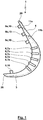
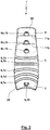
- FIGs. 1 to 7 an expansion body 1 of a thumb orthosis 2 is shown.
- the expansion body 1 has (in the plan view according to Fig. 1 ) via two basically straight side legs 3, 4, which are connected to one another via a curved base leg 5.
- the expansion body 1 is arched in its cross section in such a way that the expansion body 1 is concave in the contact area with the hand.
- the concave curvature of the cross-section changes over the longitudinal extension from the side limb 3 via the base limb 5 to the side limb 4.
- the transverse extent along the curvature also changes over the longitudinal extent of the expansion body 1, the transverse extent of the expansion body 1 in the area of the curved base leg 5 is larger than in the area of the side legs 3, 4.
- the transverse extension of the expansion body 1 decreases continuously from the maximum width approximately in the middle of the base leg 5 to the free end areas of the side legs 3, 4.
- the expansion body 1 can be placed on the The side that does not form the contact surface with the hand can be equipped with guide elements 6, here guide ribs 7a, 7b, 7c, 7d, 7e.
- the expansion body 1 optionally has at least one coupling device 8 or 9a, 9b, 9c in the area of the side limb 3 and / or in the area of the side limb 4.
- the coupling devices 8, 9 are mushroom heads 10 formed integrally by the expansion body 1.
- predetermined separation points 11a, 11b are provided in the area of at least one side leg 3, 4 predetermined separation points 11a, 11b.
- the intended separation points 11a, 11b enable a reduction in the length of the associated side limb 3, 4. It is possible that a coupling device 9a, 9b is also separated when the length of a side limb 3, 4 is shortened.
- the intended separation points 11a, 11b are designed as material recesses or weakenings in the form of grooves.
- a length 12 of the side leg 3 is 11 mm, while a length 13 of the side leg 4 can be 30 mm.
- the radius of curvature 14 of the base leg 5 can be 25 mm.
- An opening angle 15 of the two side legs 3, 4 can be 60 °, which is ensured by the corresponding circumferential angle and the curvature of the base leg 5.
- the transverse extent of the expansion body 1 changes over its longitudinal extent.
- the smallest transverse extent 16 of the side leg 3 in its free end area can be 19 mm, while the largest transverse extent 17 of the base leg 5 can be 24 mm and the smallest transverse extent 18 of the side leg 4 in its free end area can be 19 mm.
- the transverse extension changes continuously.
- the cross section of the expansion body 1 is curved with a radius of curvature 19 which can be 19 mm.
- the radius of curvature 20 can be 12 mm.
- the radius of curvature 21 can be 37 mm.
- the dimensions can be adapted, the aforementioned dimensions preferably applying to a hand size 25. It is possible that the opening angle 15 deviates by ⁇ 20 ° (preferably ⁇ 15 ° or ⁇ 10 ° or ⁇ 5 °) from the specified opening angle of 60 °. With regard to the other dimensions, it applies that these can deviate by ⁇ 50%, ⁇ 20%, ⁇ 15%, ⁇ 10% or ⁇ 5% from the specified dimensions.
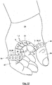
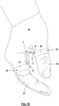
- Figs. 8-11 show a thumb orthosis 2, which consists of the expansion body 1 according to Figs. 1 to 7 and holding devices 22, 23 attached to the end and placed against a hand 24.
- the expansion body 1 rests with the concavely curved inside of the base leg 5 against the transition from the thumb 26 to the index finger 27, which is referred to here as the thumb arch 25.
- the thumb arch 25 Due to the concave curvature of the thumb arch 25 facing side of the expansion body 1, the cross section of the base leg 5 partially surrounds the thumb bow 25. In other words, the thumb bow 25 enters the concave recess of the base leg 5.
- the thumb 26 rests on the side leg 3.
- the length of the side leg 3 is preferably dimensioned in such a way that it extends approximately to the foremost thumb joint or ends shortly before it. As a result of the concave curvature of the side leg 3, it also partially surrounds the thumb 26 in cross section.
- the index finger 27 rests on the side leg 4.
- the cross section of the side leg 4 partially surrounds the index finger 27.
- the length of the side leg 4 is preferably dimensioned such that it extends approximately to the second foremost joint of the index finger 27 or short ends here.
- the side limb 3 carries the holding device 22 in a free end region 28.
- a free end region 29 of the side limb 4 accordingly bears the holding device 23.
- the holding devices 22, 23 each have a holding strip 30, 31.
- the holding strip 30 is designed in the manner of a ring or loop and completely surrounds the thumb 26.
- the side leg 3 is pressed against the thumb 26 by the holding strip 30, in particular under elastic pretension. The same applies to the holding strip 31 and the index finger 27.
- Fig. 8 shows the hand 24 with the thumb orthosis 2 in the applied state, whereby the user does not apply any force to the thumb 26 and the index finger 27, so that the alignment of the thumb 26 and the index finger 27 is predetermined by the spreader body 1 corresponding to the opening angle 15, whereby a basic position is guaranteed.
- Fig. 9 shows the thumb orthosis 2 in a state in which the expansion body 1 is elastically deformed by the user generating forces that move the thumb 26 in the direction of the index finger 27.
- the forces generated lead to the elastic deformation of the expansion body, especially in the area of the base leg 5, which reduces the opening angle 15 and thus the distance between the thumb 26 and the index finger 27 (in the area of its contact surface on the side legs 3, 4) can be reduced.
- Fig. 9 shows the so-called "forceps grip". It is possible that the opening angle of 60 ° in the basic position due to the applied forces up to 10 °, 0 ° or even according to Fig. 9 up to a negative angle such that the side legs 3, 4 no longer diverge, but rather converge, changes.
- Fig. 10 shows the use of the thumb orthosis 2 for writing with a pen 32. It can be seen that the pen 32 rests against the guide ribs 7 and is guided by them in a form-fitting manner.
- the holding strips 30, 31 are connected to one another at the ends by means of connecting devices 33, 34, which are designed here as Velcro fasteners 35, 36.
- the holding strips 30, 31 can be closed tightly around the thumb 26 or the index finger 27 via the Velcro fasteners 35, 36.
- the holding strips 30, 31 are designed as textile strips or Velcro strips that are firmly connected to the expansion body 1, for example by gluing or sewing.
- the holding strips 30, 31 are designed as perforated strips 37, 38.
- the holding strips 30 are preferably elastic, for example as rubber strips.
- a hole in one end area of the retaining strip 30, 31 is then plugged onto a mushroom head 10 of the expansion body 1 and after the thumb 26 or index finger 27 has been looped around another end area of the retaining strip is plugged onto the mushroom head 10 in the area of a further hole. Since the retaining strips 30, 31 have a large number of holes distributed over their length, depending on the choice of the hole for attachment to the mushroom head 10, an adaptation to different diameters of the thumb 26 or index finger 27 and / or to different desired contact forces respectively. It is possible that the holding strips 30, 31 also have predetermined separation points, via which an excess length of the holding strips 30, 31 can then be separated.
- Fig. 13 shows a different embodiment of the holding devices 22, 23.
- the holding strips 30, 31 are not flexible but are inherently rigid.
- holding strips 30a, 30b and 31a, 31b each extend from the base body of the expansion body 1 in different circumferential directions around the thumb 26 or the index finger 27, whereby these are guided past one another for the illustrated embodiment and thus have an overlap without this is necessarily the case.
- the holding strips 30a, 30b or 31a, 31b have elasticity and their inherently rigid shape is predetermined in such a way that when the thumb 26 or index finger 27 is threaded in, the holding strips 30a, 30b or 31a, 31b are elastically expanded, whereby the holding strips 30a, 30b or 31a, 31b are braced in the applied position with the thumb 26 or the index finger 27 and thus fix the thumb orthosis 2 on the hand 24. It is possible that (as in Fig. 13 shown) the retaining strips 30a, 30b, 31a, 31b are integrally connected to the expansion body 1, which is possible, for example, when the expansion body 1 with the retaining strips 30a, 30b, 31a, 31b is manufactured in an injection molding process.
- retaining strips 30a, 30b, 31a, 31b can be designed as a composite body. So shows Fig. 14 an embodiment in which metal strips 39a, 39b, 40a, 40b are embedded in the holding strips 30a, 30b, 31a, 31b, which are made, for example, of plastic, which on the one hand allow plastic deformation to adapt to the hand 24 and, on the other hand, any ensure the required elasticity.
- the expansion body 1 lies against the hand, namely the thumb 26, the thumb arch 25 and the index finger 27, over its entire extent.
- the expansion body 1 represents a type of clasp or bridge between the holding devices 22, 23, in which the expansion body 1 extends between the thumb 26 and the index finger 27 without contact with the thumb arch 25.
- the expansion body 1 can then have any desired geometry and, for example, be designed as an elastic bracket or bending bar or as an elastic pull and / or push rod.
- the holding devices 22, 23 are connected to the expansion body 1 via coupling devices 8, 9, which under certain circumstances also form a type of joint, thus ensuring a degree of pivoting freedom between the expansion body 1 and the holding devices 22, 23.
- FIG. 15 shows the basic position in which the expansion body 1 is not elastically clamped
- Fig. 16 elastic tensioning of the expansion body 1 as a result of the forces applied by the thumb 26 and index finger 27 for the purpose of bringing the thumb 26 closer to the index finger 27.
- Fig. 17 shows schematically the force 41 acting on the thumb orthosis 2, here the expansion body 1, during use.
- the expansion body 1 preferably consists of a thermoplastic polyurethane.
- the expansion body can have a Shore A hardness of 80 ( ⁇ 20 or 15 ⁇ or ⁇ 10 or ⁇ 5) or a Shore A hardness of 90 ( ⁇ 20 or 15 ⁇ or ⁇ 10 or ⁇ 5). It is also possible, however, for the expansion body 1 to be made of a polyurethane or silicone.
- the thumb orthosis 2 can be used in daily use without significantly impairing the use of the hand 24.
- the thumb orthosis 2 is easily removable and can be cleaned easily.
- the length of the retaining strips 30, 31 it is also possible for the length of the retaining strips 30, 31 to be adapted as required by cutting.
- a plurality of coupling devices 8, 9, in particular mushroom heads 10 are distributed in the direction of the longitudinal extension or also arranged next to one another on the expansion body 1. It is possible, for example, for coupling devices 8, 9 or mushroom heads 10 to be provided in the manner of double rows on the expansion body 1. Excess coupling devices 8, 9, in particular mushroom heads 10, can also be removed.
- a longer retaining strip can also be used, which then extends in the manner of a spiral around the thumb 26 or the index finger 27.
- the thumb orthosis 2 according to the invention can be put on and put down again in a particularly simple manner and is space-saving both when it is worn and when it is stored.
- the adaptability allows the number of models required for the required range of hand sizes to be reduced. It is also possible that the same thumb orthosis can be used for wearing on the right hand as well as on the left hand.
Landscapes
- Health & Medical Sciences (AREA)
- Nursing (AREA)
- Orthopedic Medicine & Surgery (AREA)
- Engineering & Computer Science (AREA)
- Biomedical Technology (AREA)
- Heart & Thoracic Surgery (AREA)
- Vascular Medicine (AREA)
- Life Sciences & Earth Sciences (AREA)
- Animal Behavior & Ethology (AREA)
- General Health & Medical Sciences (AREA)
- Public Health (AREA)
- Veterinary Medicine (AREA)
- Orthopedics, Nursing, And Contraception (AREA)
Priority Applications (4)
| Application Number | Priority Date | Filing Date | Title |
|---|---|---|---|
| EP19169043.7A EP3721840A1 (fr) | 2019-04-12 | 2019-04-12 | Orthèse de pouce et ensemble pourvu d'une pluralité d'orthèses |
| EP20714652.3A EP3952800B1 (fr) | 2019-04-12 | 2020-04-03 | Orthèse de pouce et ensemble pourvu d'une pluralité d'orthèses |
| PCT/EP2020/059547 WO2020207916A1 (fr) | 2019-04-12 | 2020-04-03 | Orthèse du pouce et ensemble comprenant plusieurs orthèses du pouce |
| US17/498,450 US12310872B2 (en) | 2019-04-12 | 2021-10-11 | Thumb orthosis and set of a plurality of thumb orthoses |
Applications Claiming Priority (1)
| Application Number | Priority Date | Filing Date | Title |
|---|---|---|---|
| EP19169043.7A EP3721840A1 (fr) | 2019-04-12 | 2019-04-12 | Orthèse de pouce et ensemble pourvu d'une pluralité d'orthèses |
Publications (1)
| Publication Number | Publication Date |
|---|---|
| EP3721840A1 true EP3721840A1 (fr) | 2020-10-14 |
Family
ID=66175295
Family Applications (2)
| Application Number | Title | Priority Date | Filing Date |
|---|---|---|---|
| EP19169043.7A Withdrawn EP3721840A1 (fr) | 2019-04-12 | 2019-04-12 | Orthèse de pouce et ensemble pourvu d'une pluralité d'orthèses |
| EP20714652.3A Active EP3952800B1 (fr) | 2019-04-12 | 2020-04-03 | Orthèse de pouce et ensemble pourvu d'une pluralité d'orthèses |
Family Applications After (1)
| Application Number | Title | Priority Date | Filing Date |
|---|---|---|---|
| EP20714652.3A Active EP3952800B1 (fr) | 2019-04-12 | 2020-04-03 | Orthèse de pouce et ensemble pourvu d'une pluralité d'orthèses |
Country Status (3)
| Country | Link |
|---|---|
| US (1) | US12310872B2 (fr) |
| EP (2) | EP3721840A1 (fr) |
| WO (1) | WO2020207916A1 (fr) |
Cited By (2)
| Publication number | Priority date | Publication date | Assignee | Title |
|---|---|---|---|---|
| US20230118557A1 (en) * | 2020-03-31 | 2023-04-20 | Bauerfeind Ag | Thumb orthosis |
| WO2024259460A1 (fr) | 2023-06-19 | 2024-12-26 | Eicher Stefan | Dispositif de support |
Families Citing this family (1)
| Publication number | Priority date | Publication date | Assignee | Title |
|---|---|---|---|---|
| US12004989B2 (en) * | 2020-04-01 | 2024-06-11 | Spl Int, Llc | Splint for supporting an injured limb and/or appendage |
Citations (8)
| Publication number | Priority date | Publication date | Assignee | Title |
|---|---|---|---|---|
| DE19511116A1 (de) | 1995-03-25 | 1996-09-26 | Heinz Scheffler | Daumenorthese |
| DE202006011664U1 (de) | 2006-07-26 | 2006-11-02 | Thämert Orthopädische Hilfsmittel GmbH & Co. KG | Mittelhand-Daumen-Orthese |
| JP2011194187A (ja) * | 2010-03-17 | 2011-10-06 | Shizune Nagano | 関節サポーター |
| US20120179081A1 (en) * | 2009-07-17 | 2012-07-12 | Gerard Anglada | Orthosis for treating rhizarthrosis |
| WO2013160478A1 (fr) | 2012-04-26 | 2013-10-31 | Bsn Medical Gmbh | Orthèse du pouce |
| US20160296359A1 (en) * | 2015-04-09 | 2016-10-13 | Ossur Iceland Ehf | Hand support and method for using the same |
| DE102016010135A1 (de) | 2015-08-21 | 2017-02-23 | WE Design B.V. | Orthese zur Ruhigstellung des Karpometakarpalgelenks I |
| JP2017080354A (ja) * | 2015-10-23 | 2017-05-18 | 邦子 平井 | 親指腱鞘炎用関節固定器具 |
Family Cites Families (10)
| Publication number | Priority date | Publication date | Assignee | Title |
|---|---|---|---|---|
| US4143653A (en) * | 1977-03-21 | 1979-03-13 | Heins Wichman | Splinting of members |
| US5584799A (en) * | 1989-09-11 | 1996-12-17 | Gray; James C. | Splint/therapeutic device |
| US5770297A (en) * | 1996-10-01 | 1998-06-23 | Grubich; Ivan J. | Gripping device |
| US5762621A (en) * | 1996-10-23 | 1998-06-09 | Schultz; Anne | Hand tendon support system |
| US6520925B1 (en) * | 2000-09-06 | 2003-02-18 | Calvin Thibodo, Jr. | Splint system for the thumb |
| JP4253235B2 (ja) | 2003-09-02 | 2009-04-08 | 日本シグマックス株式会社 | 関節サポーター用ステー及びその製造方法 |
| ITVR20050153A1 (it) * | 2005-12-06 | 2007-06-07 | Fgp Srl | Supporto ortopedico od ortesi per la mano, in particolare per il pollice |
| US9555567B2 (en) * | 2007-07-16 | 2017-01-31 | Madgrip Holdings, Llc | Utility glove |
| JP5587106B2 (ja) | 2010-09-13 | 2014-09-10 | 株式会社松本義肢製作所 | 作業用サポーター |
| DE202014005449U1 (de) * | 2014-07-04 | 2014-07-25 | Spörer AG | Handgelenkbandage zur Stabilisierung und/oder Entlastung des proximalen Handgelenkes bei der Durchführung von Montagearbeiten |
-
2019
- 2019-04-12 EP EP19169043.7A patent/EP3721840A1/fr not_active Withdrawn
-
2020
- 2020-04-03 EP EP20714652.3A patent/EP3952800B1/fr active Active
- 2020-04-03 WO PCT/EP2020/059547 patent/WO2020207916A1/fr not_active Ceased
-
2021
- 2021-10-11 US US17/498,450 patent/US12310872B2/en active Active
Patent Citations (8)
| Publication number | Priority date | Publication date | Assignee | Title |
|---|---|---|---|---|
| DE19511116A1 (de) | 1995-03-25 | 1996-09-26 | Heinz Scheffler | Daumenorthese |
| DE202006011664U1 (de) | 2006-07-26 | 2006-11-02 | Thämert Orthopädische Hilfsmittel GmbH & Co. KG | Mittelhand-Daumen-Orthese |
| US20120179081A1 (en) * | 2009-07-17 | 2012-07-12 | Gerard Anglada | Orthosis for treating rhizarthrosis |
| JP2011194187A (ja) * | 2010-03-17 | 2011-10-06 | Shizune Nagano | 関節サポーター |
| WO2013160478A1 (fr) | 2012-04-26 | 2013-10-31 | Bsn Medical Gmbh | Orthèse du pouce |
| US20160296359A1 (en) * | 2015-04-09 | 2016-10-13 | Ossur Iceland Ehf | Hand support and method for using the same |
| DE102016010135A1 (de) | 2015-08-21 | 2017-02-23 | WE Design B.V. | Orthese zur Ruhigstellung des Karpometakarpalgelenks I |
| JP2017080354A (ja) * | 2015-10-23 | 2017-05-18 | 邦子 平井 | 親指腱鞘炎用関節固定器具 |
Cited By (3)
| Publication number | Priority date | Publication date | Assignee | Title |
|---|---|---|---|---|
| US20230118557A1 (en) * | 2020-03-31 | 2023-04-20 | Bauerfeind Ag | Thumb orthosis |
| US12533253B2 (en) * | 2020-03-31 | 2026-01-27 | Bauerfeind Ag | Thumb orthosis |
| WO2024259460A1 (fr) | 2023-06-19 | 2024-12-26 | Eicher Stefan | Dispositif de support |
Also Published As
| Publication number | Publication date |
|---|---|
| US20220023084A1 (en) | 2022-01-27 |
| EP3952800C0 (fr) | 2023-07-12 |
| EP3952800B1 (fr) | 2023-07-12 |
| WO2020207916A1 (fr) | 2020-10-15 |
| US12310872B2 (en) | 2025-05-27 |
| EP3952800A1 (fr) | 2022-02-16 |
Similar Documents
| Publication | Publication Date | Title |
|---|---|---|
| DE4326751C2 (de) | Hand- und Handgelenkorthese | |
| EP2841030B1 (fr) | Orthèse du pouce | |
| EP0039323B1 (fr) | Eclisse pour la réduction et l'immobilisation des fractures des doigts et du métacarpe et procédé pour leur fabrication | |
| EP3171829B1 (fr) | Dispositif pour soulager les douleurs provoquées par une affection de l'articulation carpo-métacarpienne du pouce de type dégénératif, inflammatoire et rhumatismal | |
| EP3263086B1 (fr) | Orthèse de main, élément modulaire et moyen de fixation pour une orthèse de main | |
| EP3952800B1 (fr) | Orthèse de pouce et ensemble pourvu d'une pluralité d'orthèses | |
| WO1985002537A1 (fr) | Prothese orthopedique pour l'articulation du genou | |
| DE202015008342U1 (de) | Handorthese | |
| DE112014004784T5 (de) | Patientenschnittstelle | |
| EP2090273B1 (fr) | Bandage | |
| CH702784A1 (de) | Palmare Daumen- und Daumensattelgelenk-Schiene. | |
| DE102010001583A1 (de) | Schiene zur Ruhigstellung eines Gelenks | |
| DE202013004834U1 (de) | Gel-Seitenkissen | |
| DE60110762T2 (de) | Handgelenkstütze | |
| EP2184040B1 (fr) | Pince pour épicondylite | |
| EP3474790B1 (fr) | Orthèse de la main | |
| DE102016010135A1 (de) | Orthese zur Ruhigstellung des Karpometakarpalgelenks I | |
| EP3993659B1 (fr) | Dispositif de type équipement de protection individuelle pour la stabilisation et la décharge de l'articulation trapézo-métacarpienne humaine | |
| EP1894546A1 (fr) | Orthèse pour poignet | |
| DE202020102689U1 (de) | Elastisches Korrektur- und/oder Stabilisierungsband | |
| DE202023107556U1 (de) | Elastisch verformbarer Korrektur- und/oder Stabilisierungsstreifen, insbesondere zur Therapierung eines Daumensattelgelenks | |
| EP3871640A1 (fr) | Orthèse pour l'articulation carpo-métacarpienne de pouce | |
| EP2977031B1 (fr) | Orthèse épicondylienne | |
| DE102022115336B3 (de) | Orthese für das Daumensattelgelenk | |
| DE102013009260A1 (de) | Fingerschiene mit einer ersten und einer zweiten miteinander elastisch verbundenen Teilschiene |
Legal Events
| Date | Code | Title | Description |
|---|---|---|---|
| PUAI | Public reference made under article 153(3) epc to a published international application that has entered the european phase |
Free format text: ORIGINAL CODE: 0009012 |
|
| STAA | Information on the status of an ep patent application or granted ep patent |
Free format text: STATUS: THE APPLICATION HAS BEEN PUBLISHED |
|
| AK | Designated contracting states |
Kind code of ref document: A1 Designated state(s): AL AT BE BG CH CY CZ DE DK EE ES FI FR GB GR HR HU IE IS IT LI LT LU LV MC MK MT NL NO PL PT RO RS SE SI SK SM TR |
|
| AX | Request for extension of the european patent |
Extension state: BA ME |
|
| STAA | Information on the status of an ep patent application or granted ep patent |
Free format text: STATUS: THE APPLICATION IS DEEMED TO BE WITHDRAWN |
|
| 18D | Application deemed to be withdrawn |
Effective date: 20210415 |