EP3721940B1 - Erzeugung einer vielzahl von behandlungsplänen für die strahlentherapie - Google Patents
Erzeugung einer vielzahl von behandlungsplänen für die strahlentherapie Download PDFInfo
- Publication number
- EP3721940B1 EP3721940B1 EP19168982.7A EP19168982A EP3721940B1 EP 3721940 B1 EP3721940 B1 EP 3721940B1 EP 19168982 A EP19168982 A EP 19168982A EP 3721940 B1 EP3721940 B1 EP 3721940B1
- Authority
- EP
- European Patent Office
- Prior art keywords
- fluence
- treatment
- treatment plans
- radiation
- plans
- Prior art date
- Legal status (The legal status is an assumption and is not a legal conclusion. Google has not performed a legal analysis and makes no representation as to the accuracy of the status listed.)
- Active
Links
Images

Classifications
-
- A—HUMAN NECESSITIES
- A61—MEDICAL OR VETERINARY SCIENCE; HYGIENE
- A61N—ELECTROTHERAPY; MAGNETOTHERAPY; RADIATION THERAPY; ULTRASOUND THERAPY
- A61N5/00—Radiation therapy
- A61N5/10—X-ray therapy; Gamma-ray therapy; Particle-irradiation therapy
- A61N5/103—Treatment planning systems
-
- A—HUMAN NECESSITIES
- A61—MEDICAL OR VETERINARY SCIENCE; HYGIENE
- A61N—ELECTROTHERAPY; MAGNETOTHERAPY; RADIATION THERAPY; ULTRASOUND THERAPY
- A61N5/00—Radiation therapy
- A61N5/10—X-ray therapy; Gamma-ray therapy; Particle-irradiation therapy
- A61N5/103—Treatment planning systems
- A61N5/1031—Treatment planning systems using a specific method of dose optimization
-
- A—HUMAN NECESSITIES
- A61—MEDICAL OR VETERINARY SCIENCE; HYGIENE
- A61N—ELECTROTHERAPY; MAGNETOTHERAPY; RADIATION THERAPY; ULTRASOUND THERAPY
- A61N5/00—Radiation therapy
- A61N5/10—X-ray therapy; Gamma-ray therapy; Particle-irradiation therapy
- A61N5/1042—X-ray therapy; Gamma-ray therapy; Particle-irradiation therapy with spatial modulation of the radiation beam within the treatment head
- A61N5/1043—Scanning the radiation beam, e.g. spot scanning or raster scanning
-
- A—HUMAN NECESSITIES
- A61—MEDICAL OR VETERINARY SCIENCE; HYGIENE
- A61N—ELECTROTHERAPY; MAGNETOTHERAPY; RADIATION THERAPY; ULTRASOUND THERAPY
- A61N5/00—Radiation therapy
- A61N5/10—X-ray therapy; Gamma-ray therapy; Particle-irradiation therapy
- A61N5/1042—X-ray therapy; Gamma-ray therapy; Particle-irradiation therapy with spatial modulation of the radiation beam within the treatment head
- A61N5/1045—X-ray therapy; Gamma-ray therapy; Particle-irradiation therapy with spatial modulation of the radiation beam within the treatment head using a multi-leaf collimator, e.g. for intensity modulated radiation therapy or IMRT
-
- A—HUMAN NECESSITIES
- A61—MEDICAL OR VETERINARY SCIENCE; HYGIENE
- A61N—ELECTROTHERAPY; MAGNETOTHERAPY; RADIATION THERAPY; ULTRASOUND THERAPY
- A61N5/00—Radiation therapy
- A61N5/10—X-ray therapy; Gamma-ray therapy; Particle-irradiation therapy
- A61N5/1077—Beam delivery systems
- A61N5/1081—Rotating beam systems with a specific mechanical construction, e.g. gantries
-
- A—HUMAN NECESSITIES
- A61—MEDICAL OR VETERINARY SCIENCE; HYGIENE
- A61N—ELECTROTHERAPY; MAGNETOTHERAPY; RADIATION THERAPY; ULTRASOUND THERAPY
- A61N5/00—Radiation therapy
- A61N5/10—X-ray therapy; Gamma-ray therapy; Particle-irradiation therapy
- A61N2005/1085—X-ray therapy; Gamma-ray therapy; Particle-irradiation therapy characterised by the type of particles applied to the patient
- A61N2005/1087—Ions; Protons
Definitions
- the present disclosure relates to the field of radiation therapy and in particular to generating such plans while restricting to a subset of fluence elements.
- Multi-criteria optimization (MCO) for radiation therapy planning is a development that allows users to modify a navigated dose distribution, e.g. through a set of slider bars, where each slider bar represents a criterion affecting the dose distribution.
- the navigated dose is a convex combination of the dose distributions for a pre-calculated set of base plans (a convex combination is a weighted average where the weights are nonnegative and sum to one).
- the navigated dose distribution is updated in real-time based on the current slider positions.
- the navigation is directly deliverable if the navigated dose distribution can be recreated exactly by a feasible treatment plan, i.e. a plan that takes all limitations of the delivery system with respect to the plan parameters into account.
- Directly deliverable navigation for scanned ions is nontrivial despite that the relationship between physical dose and spot weights is linear.
- Linearity means that the convex combination of the spot weights of the base plans, where the convex coefficients are identical to those used for the navigated dose distribution, defines a treatment plan that exactly recreates the navigated dose distribution.
- These navigated spot weights must, however, satisfy certain limits that require each weight to either be zero or between some lower and upper bound. These bounds may be fixed or depend on beam energy.
- the spot weight bounds may also depend on the length of the spot segment.
- the navigated spot weights are in general not feasible with respect to the limits even if all the spot weights of the base plans are feasible.
- arc-based photon beam radiation therapy such as tomotherapy and volumetric modulated arc therapy (VMAT)
- VMAT volumetric modulated arc therapy
- post-processing can be used to arrive at a deliverable treatment plan. For example, navigated spot weights that are infeasible with respect to the spot weight limits are rounded to the closest feasible value.
- Such post-processing causes the dose distribution of the deliverable plan deviate from the navigated dose distribution. The need to compensate for discrepancies between the navigated dose distribution and the dose distribution of the deliverable plan can make the treatment planning workflow a time-consuming trial and error process.
- One objective is to improve how a deliverable treatment plan is achieved.
- a method for generating a plurality of treatment plans for radiation therapy each treatment plan specifying weights for a plurality of geometrically defined fluence elements.
- Each weight defines an amount of radiation fluence, to thereby provide radiation dose to a target volume.
- the method is performed in a treatment planning system and comprises the steps of: generating a first set of treatment plans; determining a subset of the fluence elements, based on the first set of treatment plans; and generating a second set of at least two treatment plans, wherein the treatment plans only contain weights for the subset of fluence elements.
- Each non-zero weight of a fluence element in the second set of treatment plans may be greater than or equal to a minimum weight.
- the first set of treatment plans may be a result of optimization with respect to a first multi-criteria optimization problem and the second set of treatment plans may be a result of optimization with respect to a second multi-criteria optimization problem.
- the method may further comprise the step of using the second set of treatment plans in an operator navigation system, which comprises calculating a navigated dose distribution by interpolation of dose distributions associated with the second set of treatment plans.
- the step of using the second set of treatment plans in the operator navigation system may comprise providing a graphical user interface visualizing the navigated dose distribution and a navigation control interface, the navigation control interface allowing an operator to adjust the navigated dose distribution.
- the step of determining a subset of the fluence elements may comprise discarding fluence elements having a statistical measure less than a threshold weight, the statistical measure being calculated for each fluence element across all treatment plans in the first set of treatment plans.
- the statistical measure may comprise a mean value and/or a percentile value.
- the step of determining a subset of the fluence elements may comprise ensuring there is a sufficient density of fluence elements across the whole target volume.
- Each treatment plan may be configured to be delivered using a scanned ion beam, wherein each fluence element is associated with a scanning spot of the beam, the scanning spot being defined by a scan position for the beam and a beam energy.
- Each treatment plan may be configured to be delivered using a radiation beam collimated by a binary multi-leaf collimator (MLC), wherein each leaf of the MLC can alternate between an open and a closed position.
- MLC binary multi-leaf collimator
- Each fluence element is then associated with a particular leaf of the MLC at a particular incidence direction of the beam relative to the target volume.
- Each treatment plan may be configured to be delivered using a radiation beam collimated by an MLC, wherein the leaves of the MLC are arranged into opposed leaf pairs and each leaf can assume any one of a plurality of positions between a minimum and a maximum position.
- an MLC is called a "continuous MLC.”
- Each fluence element is then associated with a bixel, each bixel being a surface element in a cross-section of the beam at a particular incidence direction relative to the target volume.
- Each incidence direction of the radiation beam relative to the target volume may be determined by either or both of a rotating gantry and a moveable couch.
- Each treatment plan may be configured to be delivered with the incidence direction of the radiation beam relative to the target volume changing during the course of the delivery.
- a treatment planning system for generating a plurality of treatment plans for radiation therapy, each treatment plan specifying weights for a plurality of geometrically defined fluence elements, each weight defining an amount of radiation fluence, to thereby provide radiation dose to a target volume.
- the treatment planning system comprises: a processor; and a memory storing instructions that, when executed by the processor, cause the treatment planning system to: generate a first set of treatment plans; determine a subset of the fluence elements, based on the first set of treatment plans; and generate a second set of at least two treatment plans, wherein the treatment plans only contain weights for the subset of fluence elements.
- a computer program for generating a plurality of treatment plans for radiation therapy, each treatment plan specifying weights for a plurality of geometrically defined fluence elements, each weight defining an amount of radiation fluence, to thereby provide radiation dose to a target volume
- the computer program comprising computer program code which, when run on a treatment planning system causes the treatment planning system to: generate a first set of treatment plans; determine a subset of the fluence elements, based on the first set of treatment plans; and generate a second set of at least two treatment plans, wherein the treatment plans only contain weights for the subset of fluence elements.
- a computer program product comprising a computer program according to claim the third aspect and a computer readable means on which the computer program is stored.
- FIG 1 is a schematic drawing illustrating an environment in which embodiments presented herein can be applied.
- a treatment planning system 1 determines how radiation is to be delivered to a target volume 3. More specifically, the treatment planning system supplies a treatment plan 12 to a radiation delivery system 2.
- the treatment plan 12 specifies weights for a plurality of geometrically defined fluence elements. Each weight defines an amount of radiation fluence, to thereby provide radiation dose to the target volume 3.
- the radiation delivery system 2 generates the beam and delivers the dose differs depending on the treatment modality (such as photons, electrons, or ions) and geometric configuration, as is well known in the art per se.
- the common goal is to deliver a dose to the target volume 3 (i.e. the tumor) that is as close as possible to a prescribed dose while minimizing the dose to organs at risk 5, which depends on where the tumor is located.
- the treatment plan is delivered using a scanned ion beam.
- each fluence element is associated with a scanning spot of the beam.
- the scanning spot is defined by a lateral scan position for the beam and a beam energy.
- the fluence element of a spot is defined as the fluence delivered between two scan positions.
- the treatment plan is made up of a set of energy layers, each containing a distribution of scanning spots for ion beam therapy. This is communicated as a treatment plan 12 to an ion beam system.
- the ion beam system Based on the treatment plan 12, the ion beam system generates an ion beam 7 that is scanned spot by spot over the target volume 3 of a patient. Each scanning spot generates a spot dose distribution in the target volume 3 of the patient.
- depth is represented along a z-axis and the y-axis is upwards.
- the view in Fig 1 can thus be considered to be a side view.
- the location of the dose maximum (Bragg peak) of a spot dose distribution depth-wise, i.e. along the z-axis, is controlled by the kinetic energy of the ions; higher energy results in a deeper location of the dose maximum.
- the lateral position, along the y-axis and x-axis is controlled using electromagnets to deflect the beam 7.
- scanning spots can be provided to achieve a dose distribution covering the target volume 3 in three dimensions.
- the treatment plan is delivered during rotational movement of the machine gantry and/or patient couch.
- the patient couch can be subject to translational movements during the course of the delivery.
- the positions of the machine gantry and patient couch at any one time defines an incidence direction.
- the treatment machine is equipped with a binary MLC. While moving, the configuration of the binary MLC can be adjusted by having each leaf fully open or fully closed, i.e. in a binary configuration.
- Each treatment plan is then delivered using a radiation beam collimated by the binary MLC, such that each leaf of the MLC can alternate between an open and a closed position.
- each fluence element is associated with a particular leaf of the MLC at a particular incidence direction of the beam relative to the target volume.
- the MLC can be a continuous MLC, in which the leaves can assume any one of a plurality of positions between a maximum position (e.g. fully open) and a minimum position (e.g. fully closed).
- each fluence element is associated with a bixel, which is a surface element in a cross-section of the beam at a particular incidence direction relative to the target volume.
- each incidence direction of the radiation beam relative to the target volume is determined by either or both of a rotating machine gantry and a moveable patient couch.
- Fig 2 is a schematic diagram illustrating functional modules of the treatment planning system of Fig 1 according to one embodiment.
- the treatment planning system comprises an optimization module 10 and a navigation module 11. Each of these modules 10, 11 can be implemented in software.
- the optimization module 10 creates several base plans which are optimized for different criteria. According to embodiments presented below, the base plans correspond to the second set of treatment plans.
- the navigation module 11 allows the user to modify a navigated dose distribution through a set of slider bars, where each slider bar represents a criterion affecting the dose distribution.
- the navigated dose distribution is a convex combination of the dose distributions for the set of base plans.
- the navigated dose distribution is updated in real-time based on the current slider positions. According to embodiments presented herein, the navigated dose distribution is directly deliverable by the radiation delivery system.
- Fig 3 is a schematic drawing illustrating the Bragg peak positions of the energy layers of the target volume 3 of Fig 1 when radiation is delivered using a scanned ion beam.
- Fig 3 is a side view, from the same perspective as the view of Fig 1 .
- the depth of the Bragg peak depends on energy level.
- the Bragg peak depths of four energy levels 17a-d are shown in the target volume 3.
- a first energy level 17a is illustrated by a line where the Bragg peaks occur for that energy level when ions of a first amount of energy, but with different lateral deflections are supplied using the ion beam therapy in the system of Fig 1 .
- a second energy level 17b is illustrated by a line where the Bragg peaks occur when ions of a second amount of energy are supplied, etc. It is to be noted that the density of tissue that the ion beam passes through affects the depth. For instance, if the beam passes through bone this results in a different depth of the Bragg peak than if the beam passes through only soft tissue. Consequently, the Bragg peak depth of each energy level 17a-d does not need to be a straight line of a certain depth.
- Fig 4 is a schematic drawing illustrating the lateral distribution of scanning spots in one of the energy layers (see 17a-d) of Fig 3 according to one embodiment.
- the energy layer is shown along an x-y plane. While the energy layer does not need to be completely flat in the target volume of the patient, the energy layer is here depicted as a flattened layer.
- Scanning spots 14, illustrated as circles in Fig 4 are provided throughout the energy layer to cover the target volume 3 at that energy layer.
- the weight which can e.g. be applied by controlling the scanning time at a certain spot, can differ between scanning spots.
- the weight of each scanning spot must be greater than or equal to a minimum spot weight, which may be dependent on how fast a kicker magnet is able to open and close the beam line of the ion beam delivery system.
- Fig 4 only discloses the distribution of scanning spots in one energy layer, there are corresponding distributions of scanning spots for each energy layer to be used for a target volume.
- Fig 5 is a schematic perspective view of a treatment machine, illustrating a radiation delivery system for arc-based radiation therapy.
- a Cartesian coordinate system in dimensions x, y, and z is also shown. It is to be noted that this coordinate system differs from the coordinate system of Fig 1, Fig 3 and Fig 4 .
- a gantry 31 is rotatable around a gantry axis which is here parallel to the z-axis.
- a gantry angle 36 defines the extent of the gantry rotation. It is not important from where the gantry angle 36 is defined, as long as this definition is consistent.
- a couch 30 is provided on which the patient (not shown) lies during treatment.
- Various fixation mechanisms known per se, can be applied to ensure the patient and the treatment volume is fixated in a known position.
- the couch 30 is rotatable around a couch axis which is here parallel to the y axis.
- a couch angle 35 defines the extent of the couch rotation. It is not important from where the couch angle 35 is defined, as long as this definition is consistent.
- the couch may be movable in the z direction.
- An MLC 33 is provided mounted to the gantry 31, through which the radiation is provided during treatment.
- the MLC 33 can be rotatable around a collimator axis.
- the collimator axis varies in its orientation (of the Cartesian coordinate system) depending on the rotation of the gantry 31.
- a collimator angle 37 defines the extent of the rotation of the MLC. It is not important from where the collimator angle 37 is defined, as long as this definition is consistent.
- a combination of values of the couch angle 35, the gantry angle 36 and optionally the collimator angle 37 define an incidence direction.
- the incidence direction defines at what angle radiation will treat the patient.
- a beam plane is a normal plane to a beam direction, i.e. the collimator axis.
- Each trajectory occurs in an arc from a start time to an end time and defines motion between incidence directions.
- the motion is in a helical form for helical tomotherapy, in which case translational movement between the couch and the gantry is enabled along the z-axis.
- Tomotherapy is a form of photon beam therapy where the patient is irradiated by a slit beam that rotates continuously around the patient.
- the rotation is discretized into a number of projections for planning purposes (normally 51 projections per rotation).
- the width of the slit is defined by a pair of movable jaws, with typical widths being 0.5 to 5 cm, and the irradiation through the slit is collimated by a set of pneumatically driven MLC leaves.
- the collimation introduced by the leaves can be binary in the sense that the leaves can only be either completely open or completely closed.
- the weights of the fluence elements correspond to the open times of the MLC leaves at a particular incidence direction. The weights, i.e.
- the leaf open times need to be greater than or equal to a lower bound for all open MLC leaves.
- the lower bound corresponds to the minimum leaf open time, which may be dependent on the shortest possible time a leaf can be in open configuration due to the finite leaf speed of the MLC.
- a weight of zero which corresponds to a closed leaf, is also possible. Weights between consecutive projection must also satisfy a minimum (non-zero) close time constraint. A close time of zero is also possible because a leaf need not close between two consecutive projections.
- the motion is performed for VMAT.
- the arc trajectory defines a motion implemented using a change in one or more of the couch angle 35, the collimator angle 37, and the gantry angle 36.
- the MLC is here in a continuous configuration, in which each leaf of the MLC can assume any one of a plurality of positions between a fully open and a closed position.
- the leaf positions for the continuous MLC are generally controlled by mechanical motors.
- the leaves are also arranged into opposed leaf pairs.
- each fluence element is associated with a bixel, which is a surface element in a cross-section of the beam (i.e. the beam plane) at a particular incidence direction relative to the target volume.
- the weight of a fluence element correspond to the amount of radiation fluence that is delivered while the bixel is not blocked by the MLC leaves.
- the bixel weight must be greater than or equal to a lower bound, which may dependent on the minimum tip gap between opposed leaves and a finite maximum leaf speed. Bixel weights of zero may also be feasible, corresponding to bixels that are always shielded by the MLC leaves.
- radiation is turned on for the whole duration of each arc trajectory.
- the speed of motion during the arc trajectory can be constant or can vary.
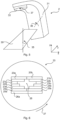
- Fig 6 is a schematic drawing illustrating the MLC 33 of Fig 5 , when applied in continuous configuration.
- the MLC 33 comprises pairs of leaves 20a-b, 21a-b, ..., 26a-b. Each leaf is movable in one dimension only.
- Each pair of opposing leaves can be positioned to provide a space in between the leaves. In this way, an opening 28 can be defined through which radiation can flow.
- the opening 28 can be tailored to cover a target volume 3, while reducing radiation to surrounding tissue. Since the leaves 20a-b, 20a-b, ..., 26a-b are only movable along a single dimension, the possible shapes of the opening 28 depend on the rotation angle 37 of the MLC 33.
- each leaf can only rest in a fully open position or a fully closed position.
- there may be leaf pairs similar to what is shown in Fig 6 , or there may be only one leaf per configurable opening, corresponding to each vertical position in Fig 6 .
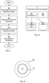
- Fig 7 is a flow chart illustrating embodiments of methods for generating a plurality of treatment plans for radiation therapy. The methods are performed in the treatment planning system of Fig 1 .
- Each treatment plan specifies weights for a plurality of geometrically defined fluence elements. Furthermore, each weight defines an amount of radiation fluence, to thereby provide radiation dose to a target volume.
- the treatment planning system In a generate 1 st set of treatment plans step 40, the treatment planning system generates a first set of treatment plans. In the generation of the first set of treatment plans, these are generated with respect to an initial set of fluence elements being selected equal for all plans in the first set of treatment plans. Moreover, the plans are generated without consideration to any (non-zero) minimum weight for the fluence elements. Nevertheless, a consideration of a maximum weight can be included in the generation of the first set of treatment plans. Each treatment plan in the first set of treatment plans can represent a particular optimization criterion, or a particular weighting of more than one criterion.
- the treatment planning system determines a subset of the fluence elements, based on the first set of treatment plans. This can comprise discarding fluence elements having a statistical measure less than a threshold weight.
- the statistical measure is calculated for each fluence element across all treatment plans in the first set of treatment plans.
- the statistical measure can comprise a mean value or a percentile value. In this way, fluence elements which e.g. have too little weight (measured as mean value or a percentile value) across the treatment plans in the first set, are discarded since their contribution is to small to the treatment plans and may be under the minimum weight to be deliverable.
- this step comprises ensuring there is a sufficient density of fluence elements across the whole target volume. Hence, fluence elements that might have been discarded in the preceding comparison with threshold weight are not discarded in order to keep fluence elements with sufficient coverage for the target volume.
- the treatment planning system In a generate 2 nd set of treatment plans step 44, the treatment planning system generates a second set of at least two treatment plans. These treatment plans only contain weights for the subset of fluence elements, and the weight for each fluence element in the subset of fluence elements is constrained to satisfy the minimum and maximum weight requirements. Each treatment plan in the second set may correspond to a treatment plan in the first set.
- each non-zero weight of a fluence element in the second set of treatment plans is greater than or equal to a minimum weight, and less than or equal to a maximum weight.
- the minimum weight and the maximum weight can be determined based on physical limitations of the radiation delivery system.
- the fluence element is a scanning spot.
- the fluence element corresponds to a particular leaf of the MLC at a particular incidence direction of the beam relative to the target volume.
- the fluence element corresponds to a bixel being a surface element in a plane perpendicular to a particular incidence direction of the beam relative to the target volume.
- the treatment planning system uses the second set of treatment plans in an operator navigation system, such as the navigation module described above and shown in Fig 2 .
- This comprises calculating a navigated dose distribution by interpolation of dose distributions associated with the second set of treatment plans.
- the interpolation can e.g. be implemented by means of forming convex combinations of the dose distributions associated with the second set of treatment plans.
- This can comprise providing a graphical user interface visualizing the navigated dose distribution.
- a navigation control interface is also provided. The navigation control interface allows an operator to adjust the navigated dose distribution, e.g. using slider bars.
- the first set of treatment plans can be a result of optimization with respect to a first multi-criteria optimization problem
- the second set of treatment plans can be a result of optimization with respect to a second multi-criteria optimization problem.
- the optimization problems can differ between the first set and the second set of treatment plans.
- each treatment plan is configured to be delivered using a scanned ion beam (see Figs 3 and 4 ).
- each fluence element is associated with a scanning spot of the ion beam.
- each treatment plan is configured to be delivered using a radiation beam collimated by an MLC.
- the MLC can be in the form of a binary configuration or continuous configuration.
- Each treatment plan can be configured to be delivered with the incidence direction of the radiation beam relative to the target volume changing during the course of the delivery.
- the convex combination of treatment plans from the second set is directly deliverable, i.e. can be used directly in the treatment machine, which simplifies clinical decision making. Moreover, no post-processing after the MCO navigation is thus necessary to make the combination of plans deliverable. This is of great value, since post-processing can introduce errors and takes time to execute.
- Fig 8 is a schematic diagram illustrating components of the treatment planning system of Fig 1 according to one embodiment.
- a processor 60 is provided using any combination of one or more of a suitable central processing unit (CPU), multiprocessor, microcontroller, digital signal processor (DSP), application specific integrated circuit etc., capable of executing software instructions 67 stored in a memory 64, which can thus be a computer program product.
- the processor 60 can be configured to execute the method described with reference to Fig 7 above.
- the memory 64 can be any combination of random-access memory (RAM) and read only memory (ROM).
- the memory 64 also comprises persistent storage, which, for example, can be any single one or combination of magnetic memory, optical memory, solid-state memory or even remotely mounted memory.
- a data memory 66 is also provided for reading and/or storing data during execution of software instructions in the processor 60.
- the data memory 66 can be any combination of random-access memory (RAM) and read only memory (ROM).
- the treatment planning system 1 further comprises an I/O interface 62 for communicating with other external entities.
- the I/O interface 62 also includes a user interface.
- Fig 9 shows one example of a computer program product comprising computer readable means.
- a computer program 91 can be stored, which computer program can cause a processor to execute a method according to embodiments described herein.
- the computer program product is an optical disc, such as a CD (compact disc) or a DVD (digital versatile disc) or a Blu-Ray disc.
- the computer program product could also be embodied in a memory of a device, such as the computer program product 64 of Fig 8 .
- the computer program 91 is here schematically shown as a track on the depicted optical disk, the computer program can be stored in any way which is suitable for the computer program product, such as a removable solid-state memory, e.g. a Universal Serial Bus (USB) drive.
- USB Universal Serial Bus
Landscapes
- Health & Medical Sciences (AREA)
- Engineering & Computer Science (AREA)
- Biomedical Technology (AREA)
- Pathology (AREA)
- Nuclear Medicine, Radiotherapy & Molecular Imaging (AREA)
- Radiology & Medical Imaging (AREA)
- Life Sciences & Earth Sciences (AREA)
- Animal Behavior & Ethology (AREA)
- General Health & Medical Sciences (AREA)
- Public Health (AREA)
- Veterinary Medicine (AREA)
- Radiation-Therapy Devices (AREA)
Claims (15)
- Computer-implementiertes Verfahren zum Erzeugen einer Vielzahl von Behandlungsplänen (12) für die Strahlentherapie, wobei jeder Behandlungsplan Gewichte für eine Vielzahl von geometrisch definierten Fluenzelementen angibt, wobei ein Fluenzelement einem Scanpunkt eines gescannten lonenstrahls zugeordnet ist oder einer festgelegten Lamelle eines Multilamellenkollimators zugeordnet ist oder einem Bixel zugeordnet ist, wobei jedes Gewicht eine Strahlenfluenzmenge definiert, wobei dadurch einem Zielvolumen (3) eine Strahlendosis bereitgestellt wird, wobei das Verfahren in einem Behandlungsplanungssystem (1) durchgeführt wird und umfassend die Schritte:Erzeugen (40) eines ersten Satzes von Behandlungsplänen;Bestimmen (42) einer Teilmenge der Fluenzelemente, basierend auf dem ersten Satz von Behandlungsplänen, wobei Fluenzelemente, die ein statistisches Maß von weniger als einem Schwellengewicht aufweisen, verworfen werden, wobei das statistische Maß für jedes Fluenzelement über alle Behandlungspläne in dem ersten Satz von Behandlungsplänen hinweg berechnet wird; undErzeugen (44) eines zweiten Satzes von mindestens zwei Behandlungsplänen (12) derart, dass jeder Behandlungsplan in dem zweiten Satz einem Behandlungsplan in dem ersten Satz entspricht, wobei die Behandlungspläne nur Gewichte für die Teilmenge der Fluenzelemente enthalten.
- Verfahren nach Anspruch 1, wobei jedes Gewicht ungleich Null eines Fluenzelements in dem zweiten Satz von Behandlungsplänen größer als oder gleich einem Mindestgewicht ist.
- Verfahren nach Anspruch 1 oder 2, wobei der erste Satz von Behandlungsplänen ein Ergebnis einer Optimierung in Bezug auf ein erstes multikriterielles Optimierungsproblem ist und der zweite Satz von Behandlungsplänen ein Ergebnis der Optimierung in Bezug auf ein zweites multikriterielles Optimierungsproblem ist.
- Verfahren nach einem der vorstehenden Ansprüche, ferner umfassend den Schritt eines Verwendens (46) des zweiten Satzes von Behandlungsplänen in einem Bedienernavigationssystem, das das Berechnen einer navigierten Dosisverteilung durch Interpolation von Dosisverteilungen umfasst, die dem zweiten Satz von Behandlungsplänen zugeordnet sind.
- Verfahren nach Anspruch 4, wobei der Schritt des Verwendens (46) des zweiten Satzes von Behandlungsplänen in dem Bedienernavigationssystem das Bereitstellen einer grafischen Benutzeroberfläche, die die navigierte Dosisverteilung visualisiert, und einer Navigationssteueroberfläche umfasst, wobei die Navigationssteueroberfläche es einem Bediener ermöglicht, die navigierte Dosisverteilung anzupassen.
- Verfahren nach einem der vorstehenden Ansprüche, wobei das statistische Maß einen Durchschnittswert oder einen Perzentilwert umfasst.
- Verfahren nach einem der vorstehenden Ansprüche, wobei der Schritt des Bestimmens (42) einer Teilmenge der Fluenzelemente ein Sicherstellen einer ausreichenden Dichte von Fluenzelementen über das gesamte Zielvolumen (3) hinweg umfasst.
- Verfahren nach einem der vorstehenden Ansprüche, wobei jeder Behandlungsplan konfiguriert ist, um unter Verwendung eines gescannten lonenstrahls abgegeben zu werden, wobei jedes Fluenzelement einem Scanpunkt des Strahls zugeordnet ist und der Scanpunkt durch eine Scanposition für den Strahl und eine Strahlenergie definiert ist.
- Verfahren nach einem der Ansprüche 1 bis 7, wobei jeder Behandlungsplan konfiguriert ist, um unter Verwendung eines Strahlenbündels abgegeben zu werden, das durch einen binären Multilamellenkollimator, MLC, kollimiert wird, wobei jede Lamelle des MLC zwischen einer offenen und einer geschlossenen Position wechseln kann und wobei jedes Fluenzelement einer festgelegten Lamelle des MLC bei einer festgelegten Einfallsrichtung des Strahls relativ zu dem Zielvolumen zugeordnet ist.
- Verfahren nach einem der Ansprüche 1 bis 7, wobei jeder Behandlungsplan konfiguriert ist, um unter Verwendung eines Strahlenbündels abgegeben zu werden, das durch einen MLC kollimiert wird, wobei die Lamellen des MLC in gegenüberliegenden Lamellenpaaren angeordnet sind und jede Lamelle eine beliebige von einer Vielzahl von Positionen zwischen einer minimalen und einer maximalen Position einnehmen kann, wobei jedes Fluenzelement einem Bixel zugeordnet ist und jedes Bixel ein Oberflächenelement in einem Querschnitt des Strahls in einer festgelegten Einfallsrichtung relativ zu dem Zielvolumen ist.
- Verfahren nach Anspruch 9 oder 10, wobei jede Einfallsrichtung des Strahlenbündels relativ zu dem Zielvolumen durch entweder eine rotierende Gantry (31) oder eine bewegbare Liege (30) oder beidem bestimmt wird.
- Verfahren nach einem der Ansprüche 9 bis 11, wobei jeder Behandlungsplan konfiguriert ist, um mit der Einfallsrichtung des Strahlenbündels relativ zu dem Zielvolumen abgegeben zu werden, das sich im Verlauf der Abgabe ändert.
- Behandlungsplanungssystem (1) zum Erzeugen einer Vielzahl von Behandlungsplänen (12) für die Strahlentherapie, wobei jeder Behandlungsplan Gewichte für eine Vielzahl von geometrisch definierten Fluenzelementen angibt, wobei ein Fluenzelement einem Scanpunkt eines gescannten lonenstrahls zugeordnet ist oder einer festgelegten Lamelle eines Multilamellenkollimators zugeordnet ist oder einem Bixel zugeordnet ist, wobei jedes Gewicht eine Strahlenfluenzmenge definiert, wobei dadurch einem Zielvolumen (3) eine Strahlendosis bereitgestellt wird, das Behandlungsplanungssystem (1) umfassend:einen Prozessor (60); undeinen Speicher (64), der Anweisungen (67) speichert, die, wenn sie durch den Prozessor ausgeführt werden, das Behandlungsplanungssystem (1) veranlassen, das Verfahren nach Anspruch 1 durchzuführen.
- Computerprogramm (67, 91) zum Erzeugen einer Vielzahl von Behandlungsplänen (12) für eine Strahlentherapie, wobei jeder Behandlungsplan Gewichte für eine Vielzahl von geometrisch definierten Fluenzelementen angibt, wobei ein Fluenzelement einem Scanpunkt eines gescannten lonenstrahls zugeordnet ist oder einer festgelegten Lamelle eines Multilamellenkollimators zugeordnet ist oder einem Bixel zugeordnet ist, wobei jedes Gewicht eine Strahlenfluenzmenge definiert, wobei dadurch einem Zielvolumen (3) eine Strahlendosis bereitgestellt wird, das Computerprogramm umfassend Computerprogrammcode, der, wenn er auf einem Behandlungsplanungssystem (1) laufen gelassen wird, das Behandlungsplanungssystem (1) veranlasst, das Verfahren nach Anspruch 1 auszuführen.
- Computerprogrammprodukt (64, 90), umfassend ein Computerprogramm nach Anspruch 14 und ein computerlesbares Mittel, auf dem das Computerprogramm gespeichert ist.
Priority Applications (5)
| Application Number | Priority Date | Filing Date | Title |
|---|---|---|---|
| EP19168982.7A EP3721940B1 (de) | 2019-04-12 | 2019-04-12 | Erzeugung einer vielzahl von behandlungsplänen für die strahlentherapie |
| US17/594,307 US11517767B2 (en) | 2019-04-12 | 2020-03-30 | Generating a plurality of treatment plans for radiation therapy |
| PCT/EP2020/058928 WO2020207838A1 (en) | 2019-04-12 | 2020-03-30 | Generating a plurality of treatment plans for radiation therapy |
| JP2021559985A JP7737310B2 (ja) | 2019-04-12 | 2020-03-30 | 放射線療法のための複数の治療計画の生成 |
| CN202080026355.1A CN113646040B (zh) | 2019-04-12 | 2020-03-30 | 为辐射疗法生成多个治疗计划 |
Applications Claiming Priority (1)
| Application Number | Priority Date | Filing Date | Title |
|---|---|---|---|
| EP19168982.7A EP3721940B1 (de) | 2019-04-12 | 2019-04-12 | Erzeugung einer vielzahl von behandlungsplänen für die strahlentherapie |
Publications (2)
| Publication Number | Publication Date |
|---|---|
| EP3721940A1 EP3721940A1 (de) | 2020-10-14 |
| EP3721940B1 true EP3721940B1 (de) | 2024-11-13 |
Family
ID=66175267
Family Applications (1)
| Application Number | Title | Priority Date | Filing Date |
|---|---|---|---|
| EP19168982.7A Active EP3721940B1 (de) | 2019-04-12 | 2019-04-12 | Erzeugung einer vielzahl von behandlungsplänen für die strahlentherapie |
Country Status (5)
| Country | Link |
|---|---|
| US (1) | US11517767B2 (de) |
| EP (1) | EP3721940B1 (de) |
| JP (1) | JP7737310B2 (de) |
| CN (1) | CN113646040B (de) |
| WO (1) | WO2020207838A1 (de) |
Families Citing this family (6)
| Publication number | Priority date | Publication date | Assignee | Title |
|---|---|---|---|---|
| WO2022104497A1 (zh) * | 2020-11-17 | 2022-05-27 | 西安大医集团股份有限公司 | 靶点的权重确定方法、装置及放射治疗系统 |
| EP4039325B1 (de) * | 2021-02-08 | 2024-06-26 | RaySearch Laboratories AB | Strahlungsmodulatoranordnung und strahlungsabgabevorrichtung zur verwendung in der ionenbasierten strahlentherapie und planungsverfahren für ionenbasierte strahlentherapie |
| CN115154924A (zh) * | 2022-05-31 | 2022-10-11 | 深圳市奥沃医学新技术发展有限公司 | 一种辐射递送控制方法、计算机设备及存储介质 |
| CN115845279B (zh) * | 2022-12-28 | 2025-11-07 | 中国科学院近代物理研究所 | 一种离子束快速扫描照射系统 |
| US20250387644A1 (en) * | 2024-06-25 | 2025-12-25 | Siemens Healthineers International Ag | Systems and methods for generating treatment plan alternatives for radiation therapy |
| CN120393316B (zh) * | 2025-06-25 | 2025-10-03 | 华硼中子科技(杭州)有限公司 | 基于屏障算法的bnct治疗计划生成方法、装置、介质与终端 |
Family Cites Families (12)
| Publication number | Priority date | Publication date | Assignee | Title |
|---|---|---|---|---|
| DE10151987C2 (de) | 2001-10-22 | 2003-11-06 | Fraunhofer Ges Forschung | Vorbereiten der Auswahl von Steuergrößen für eine zeitlich und räumlich einzustellende Dosisverteilung eines Strahlengerätes |
| JP5521225B2 (ja) * | 2010-06-23 | 2014-06-11 | 独立行政法人放射線医学総合研究所 | 照射計画作成装置および照射計画作成プログラム |
| JP5454989B2 (ja) * | 2010-09-07 | 2014-03-26 | 独立行政法人放射線医学総合研究所 | 治療計画装置、治療計画プログラムおよび生物学的効果比算出方法 |
| DE102010062079B4 (de) * | 2010-11-26 | 2013-09-05 | Fraunhofer-Gesellschaft zur Förderung der angewandten Forschung e.V. | Anpassen einer Dosisverteilungs-Einstellung für ein technisches Gerät der Tumortherapie |
| US9700739B2 (en) * | 2014-06-17 | 2017-07-11 | Intuitive Therapeutics Sa | System and computer program product for inverse treatment planning |
| EP3103519B1 (de) * | 2015-06-12 | 2021-06-02 | RaySearch Laboratories AB | Ein verfahren, ein computerprogrammprodukt und ein computersystem für die strahlentherapie-optimierung |
| US11565126B2 (en) * | 2015-09-11 | 2023-01-31 | Varian Medical Systems International Ag | Knowledge based multi-criteria optimization for radiotherapy treatment planning |
| JP6865765B2 (ja) * | 2016-03-09 | 2021-04-28 | コーニンクレッカ フィリップス エヌ ヴェKoninklijke Philips N.V. | 強度変調放射線治療における臨床目標の達成可能性を迅速に予測する事前最適化方法 |
| EP3426345B1 (de) * | 2016-03-09 | 2021-06-23 | RefleXion Medical, Inc. | Fluenzkartenerzeugungsverfahren für strahlentherapie |
| EP3228356B1 (de) | 2016-04-07 | 2018-03-14 | RaySearch Laboratories AB | Verfahren, computerprogramm und system für optimierung eines strahlentherapiebehandlungsplans |
| JP2018108284A (ja) * | 2017-01-04 | 2018-07-12 | 株式会社東芝 | 情報処理装置、情報処理方法およびコンピュータプログラム |
| EP3421085A1 (de) * | 2017-06-28 | 2019-01-02 | RaySearch Laboratories AB | Bestimmung einer verteilung von spoten von varying grössen für ion beam therapie mit optimierung |
-
2019
- 2019-04-12 EP EP19168982.7A patent/EP3721940B1/de active Active
-
2020
- 2020-03-30 WO PCT/EP2020/058928 patent/WO2020207838A1/en not_active Ceased
- 2020-03-30 CN CN202080026355.1A patent/CN113646040B/zh active Active
- 2020-03-30 US US17/594,307 patent/US11517767B2/en active Active
- 2020-03-30 JP JP2021559985A patent/JP7737310B2/ja active Active
Also Published As
| Publication number | Publication date |
|---|---|
| CN113646040B (zh) | 2023-03-21 |
| JP2022527400A (ja) | 2022-06-01 |
| US11517767B2 (en) | 2022-12-06 |
| WO2020207838A1 (en) | 2020-10-15 |
| JP7737310B2 (ja) | 2025-09-10 |
| EP3721940A1 (de) | 2020-10-14 |
| US20220143424A1 (en) | 2022-05-12 |
| CN113646040A (zh) | 2021-11-12 |
Similar Documents
| Publication | Publication Date | Title |
|---|---|---|
| EP3721940B1 (de) | Erzeugung einer vielzahl von behandlungsplänen für die strahlentherapie | |
| EP3459595B1 (de) | Planung der vmat-behandlung mit mehrfachkriterienoptimierung und progressivem optimierungsschema | |
| CN112203723B (zh) | 用于放射治疗计划的系统 | |
| CN111936204B (zh) | 放射疗法治疗计划和递送的系统和方法 | |
| CN111093768B (zh) | 用于确定治疗计划的弧成本的方法和治疗计划系统和计算机可读装置 | |
| US8009804B2 (en) | Dose calculation method for multiple fields | |
| JP5074394B2 (ja) | 放射線治療の計画及び照射方法並びに装置 | |
| JP3775993B2 (ja) | 放射線治療計画を作成するシステム | |
| US7162008B2 (en) | Method for the planning and delivery of radiation therapy | |
| US7961843B2 (en) | Radiotherapeutic apparatus | |
| JP2022522033A (ja) | 粒子を用いた回転式の放射線治療を提供する方法 | |
| CN101848745B (zh) | 用于调强弧形治疗序列化与最优化的方法和装置 | |
| US12036422B2 (en) | Expansion of search space for multicriteria optimization in radiation treatment planning | |
| EP3175885B1 (de) | System und verfahren zur bestimmung eines bestrahlungsplans und strahlentherapiegerät | |
| JP2021175513A (ja) | ビームジオメトリを選択する方法 | |
| EP3869517A1 (de) | Erzeugen einer vielzahl potenzieller behandlungspläne zur mehrkriterienoptimierung | |
| JP7481589B2 (ja) | イオンpbs治療最適化の方法、この方法を実行するためのコンピュータプログラム製品及びコンピュータシステム | |
| JP2022514092A (ja) | パッシブイオン放射線治療計画のためのシステムおよび方法 | |
| EP4260902A2 (de) | Partikelstrahlmodulationssysteme und -verfahren | |
| JP2025513167A (ja) | 外部ビーム放射線治療プランニングのためのコンピュータベースの方法、この方法を実行するためのコンピュータプログラム及びコンピュータ | |
| WO2024137585A1 (en) | Beam filtration apparatus and method for efficient scanned beam particle arc therapy | |
| HK40006259B (en) | Vmat treatment planning using multicriteria optimization and a progressive optimization scheme | |
| HK40009062A (en) | Interactive dose manipulation using prioritized constraints |
Legal Events
| Date | Code | Title | Description |
|---|---|---|---|
| PUAI | Public reference made under article 153(3) epc to a published international application that has entered the european phase |
Free format text: ORIGINAL CODE: 0009012 |
|
| STAA | Information on the status of an ep patent application or granted ep patent |
Free format text: STATUS: THE APPLICATION HAS BEEN PUBLISHED |
|
| AK | Designated contracting states |
Kind code of ref document: A1 Designated state(s): AL AT BE BG CH CY CZ DE DK EE ES FI FR GB GR HR HU IE IS IT LI LT LU LV MC MK MT NL NO PL PT RO RS SE SI SK SM TR |
|
| AX | Request for extension of the european patent |
Extension state: BA ME |
|
| STAA | Information on the status of an ep patent application or granted ep patent |
Free format text: STATUS: REQUEST FOR EXAMINATION WAS MADE |
|
| 17P | Request for examination filed |
Effective date: 20210518 |
|
| RBV | Designated contracting states (corrected) |
Designated state(s): AL AT BE BG CH CY CZ DE DK EE ES FI FR GB GR HR HU IE IS IT LI LT LU LV MC MK MT NL NO PL PT RO RS SE SI SK SM TR |
|
| RAP3 | Party data changed (applicant data changed or rights of an application transferred) |
Owner name: RAYSEARCH LABORATORIES AB |
|
| P01 | Opt-out of the competence of the unified patent court (upc) registered |
Effective date: 20230731 |
|
| STAA | Information on the status of an ep patent application or granted ep patent |
Free format text: STATUS: EXAMINATION IS IN PROGRESS |
|
| 17Q | First examination report despatched |
Effective date: 20240208 |
|
| GRAP | Despatch of communication of intention to grant a patent |
Free format text: ORIGINAL CODE: EPIDOSNIGR1 |
|
| STAA | Information on the status of an ep patent application or granted ep patent |
Free format text: STATUS: GRANT OF PATENT IS INTENDED |
|
| INTG | Intention to grant announced |
Effective date: 20240812 |
|
| RIN1 | Information on inventor provided before grant (corrected) |
Inventor name: JANSON, MARTIN Inventor name: BOKRANTZ, RASMUS |
|
| GRAS | Grant fee paid |
Free format text: ORIGINAL CODE: EPIDOSNIGR3 |
|
| GRAA | (expected) grant |
Free format text: ORIGINAL CODE: 0009210 |
|
| STAA | Information on the status of an ep patent application or granted ep patent |
Free format text: STATUS: THE PATENT HAS BEEN GRANTED |
|
| AK | Designated contracting states |
Kind code of ref document: B1 Designated state(s): AL AT BE BG CH CY CZ DE DK EE ES FI FR GB GR HR HU IE IS IT LI LT LU LV MC MK MT NL NO PL PT RO RS SE SI SK SM TR |
|
| REG | Reference to a national code |
Ref country code: GB Ref legal event code: FG4D |
|
| RIN1 | Information on inventor provided before grant (corrected) |
Inventor name: JANSON, MARTIN Inventor name: BOKRANTZ, RASMUS |
|
| REG | Reference to a national code |
Ref country code: CH Ref legal event code: EP |
|
| REG | Reference to a national code |
Ref country code: DE Ref legal event code: R096 Ref document number: 602019061821 Country of ref document: DE |
|
| REG | Reference to a national code |
Ref country code: IE Ref legal event code: FG4D |
|
| REG | Reference to a national code |
Ref country code: LT Ref legal event code: MG9D |
|
| REG | Reference to a national code |
Ref country code: NL Ref legal event code: MP Effective date: 20241113 |
|
| PG25 | Lapsed in a contracting state [announced via postgrant information from national office to epo] |
Ref country code: IS Free format text: LAPSE BECAUSE OF FAILURE TO SUBMIT A TRANSLATION OF THE DESCRIPTION OR TO PAY THE FEE WITHIN THE PRESCRIBED TIME-LIMIT Effective date: 20250313 Ref country code: PT Free format text: LAPSE BECAUSE OF FAILURE TO SUBMIT A TRANSLATION OF THE DESCRIPTION OR TO PAY THE FEE WITHIN THE PRESCRIBED TIME-LIMIT Effective date: 20250313 Ref country code: HR Free format text: LAPSE BECAUSE OF FAILURE TO SUBMIT A TRANSLATION OF THE DESCRIPTION OR TO PAY THE FEE WITHIN THE PRESCRIBED TIME-LIMIT Effective date: 20241113 |
|
| PG25 | Lapsed in a contracting state [announced via postgrant information from national office to epo] |
Ref country code: NL Free format text: LAPSE BECAUSE OF FAILURE TO SUBMIT A TRANSLATION OF THE DESCRIPTION OR TO PAY THE FEE WITHIN THE PRESCRIBED TIME-LIMIT Effective date: 20241113 Ref country code: FI Free format text: LAPSE BECAUSE OF FAILURE TO SUBMIT A TRANSLATION OF THE DESCRIPTION OR TO PAY THE FEE WITHIN THE PRESCRIBED TIME-LIMIT Effective date: 20241113 |
|
| REG | Reference to a national code |
Ref country code: AT Ref legal event code: MK05 Ref document number: 1741223 Country of ref document: AT Kind code of ref document: T Effective date: 20241113 |
|
| PG25 | Lapsed in a contracting state [announced via postgrant information from national office to epo] |
Ref country code: BG Free format text: LAPSE BECAUSE OF FAILURE TO SUBMIT A TRANSLATION OF THE DESCRIPTION OR TO PAY THE FEE WITHIN THE PRESCRIBED TIME-LIMIT Effective date: 20241113 |
|
| PG25 | Lapsed in a contracting state [announced via postgrant information from national office to epo] |
Ref country code: ES Free format text: LAPSE BECAUSE OF FAILURE TO SUBMIT A TRANSLATION OF THE DESCRIPTION OR TO PAY THE FEE WITHIN THE PRESCRIBED TIME-LIMIT Effective date: 20241113 |
|
| PG25 | Lapsed in a contracting state [announced via postgrant information from national office to epo] |
Ref country code: NO Free format text: LAPSE BECAUSE OF FAILURE TO SUBMIT A TRANSLATION OF THE DESCRIPTION OR TO PAY THE FEE WITHIN THE PRESCRIBED TIME-LIMIT Effective date: 20250213 |
|
| PG25 | Lapsed in a contracting state [announced via postgrant information from national office to epo] |
Ref country code: AT Free format text: LAPSE BECAUSE OF FAILURE TO SUBMIT A TRANSLATION OF THE DESCRIPTION OR TO PAY THE FEE WITHIN THE PRESCRIBED TIME-LIMIT Effective date: 20241113 Ref country code: LV Free format text: LAPSE BECAUSE OF FAILURE TO SUBMIT A TRANSLATION OF THE DESCRIPTION OR TO PAY THE FEE WITHIN THE PRESCRIBED TIME-LIMIT Effective date: 20241113 Ref country code: GR Free format text: LAPSE BECAUSE OF FAILURE TO SUBMIT A TRANSLATION OF THE DESCRIPTION OR TO PAY THE FEE WITHIN THE PRESCRIBED TIME-LIMIT Effective date: 20250214 |
|
| PG25 | Lapsed in a contracting state [announced via postgrant information from national office to epo] |
Ref country code: PL Free format text: LAPSE BECAUSE OF FAILURE TO SUBMIT A TRANSLATION OF THE DESCRIPTION OR TO PAY THE FEE WITHIN THE PRESCRIBED TIME-LIMIT Effective date: 20241113 |
|
| PG25 | Lapsed in a contracting state [announced via postgrant information from national office to epo] |
Ref country code: RS Free format text: LAPSE BECAUSE OF FAILURE TO SUBMIT A TRANSLATION OF THE DESCRIPTION OR TO PAY THE FEE WITHIN THE PRESCRIBED TIME-LIMIT Effective date: 20250213 |
|
| PG25 | Lapsed in a contracting state [announced via postgrant information from national office to epo] |
Ref country code: SM Free format text: LAPSE BECAUSE OF FAILURE TO SUBMIT A TRANSLATION OF THE DESCRIPTION OR TO PAY THE FEE WITHIN THE PRESCRIBED TIME-LIMIT Effective date: 20241113 |
|
| PGFP | Annual fee paid to national office [announced via postgrant information from national office to epo] |
Ref country code: DE Payment date: 20250410 Year of fee payment: 7 |
|
| PG25 | Lapsed in a contracting state [announced via postgrant information from national office to epo] |
Ref country code: DK Free format text: LAPSE BECAUSE OF FAILURE TO SUBMIT A TRANSLATION OF THE DESCRIPTION OR TO PAY THE FEE WITHIN THE PRESCRIBED TIME-LIMIT Effective date: 20241113 |
|
| PG25 | Lapsed in a contracting state [announced via postgrant information from national office to epo] |
Ref country code: EE Free format text: LAPSE BECAUSE OF FAILURE TO SUBMIT A TRANSLATION OF THE DESCRIPTION OR TO PAY THE FEE WITHIN THE PRESCRIBED TIME-LIMIT Effective date: 20241113 |
|
| PG25 | Lapsed in a contracting state [announced via postgrant information from national office to epo] |
Ref country code: RO Free format text: LAPSE BECAUSE OF FAILURE TO SUBMIT A TRANSLATION OF THE DESCRIPTION OR TO PAY THE FEE WITHIN THE PRESCRIBED TIME-LIMIT Effective date: 20241113 |
|
| PG25 | Lapsed in a contracting state [announced via postgrant information from national office to epo] |
Ref country code: SK Free format text: LAPSE BECAUSE OF FAILURE TO SUBMIT A TRANSLATION OF THE DESCRIPTION OR TO PAY THE FEE WITHIN THE PRESCRIBED TIME-LIMIT Effective date: 20241113 |
|
| PG25 | Lapsed in a contracting state [announced via postgrant information from national office to epo] |
Ref country code: CZ Free format text: LAPSE BECAUSE OF FAILURE TO SUBMIT A TRANSLATION OF THE DESCRIPTION OR TO PAY THE FEE WITHIN THE PRESCRIBED TIME-LIMIT Effective date: 20241113 |
|
| PG25 | Lapsed in a contracting state [announced via postgrant information from national office to epo] |
Ref country code: IT Free format text: LAPSE BECAUSE OF FAILURE TO SUBMIT A TRANSLATION OF THE DESCRIPTION OR TO PAY THE FEE WITHIN THE PRESCRIBED TIME-LIMIT Effective date: 20241113 |
|
| REG | Reference to a national code |
Ref country code: DE Ref legal event code: R097 Ref document number: 602019061821 Country of ref document: DE |
|
| PG25 | Lapsed in a contracting state [announced via postgrant information from national office to epo] |
Ref country code: SE Free format text: LAPSE BECAUSE OF FAILURE TO SUBMIT A TRANSLATION OF THE DESCRIPTION OR TO PAY THE FEE WITHIN THE PRESCRIBED TIME-LIMIT Effective date: 20241113 |
|
| PLBE | No opposition filed within time limit |
Free format text: ORIGINAL CODE: 0009261 |
|
| STAA | Information on the status of an ep patent application or granted ep patent |
Free format text: STATUS: NO OPPOSITION FILED WITHIN TIME LIMIT |
|
| 26N | No opposition filed |
Effective date: 20250814 |
|
| REG | Reference to a national code |
Ref country code: CH Ref legal event code: H13 Free format text: ST27 STATUS EVENT CODE: U-0-0-H10-H13 (AS PROVIDED BY THE NATIONAL OFFICE) Effective date: 20251125 |
|
| PG25 | Lapsed in a contracting state [announced via postgrant information from national office to epo] |
Ref country code: LU Free format text: LAPSE BECAUSE OF NON-PAYMENT OF DUE FEES Effective date: 20250412 |
|
| PG25 | Lapsed in a contracting state [announced via postgrant information from national office to epo] |
Ref country code: MC Free format text: LAPSE BECAUSE OF FAILURE TO SUBMIT A TRANSLATION OF THE DESCRIPTION OR TO PAY THE FEE WITHIN THE PRESCRIBED TIME-LIMIT Effective date: 20241113 |
|
| REG | Reference to a national code |
Ref country code: BE Ref legal event code: MM Effective date: 20250430 |
|
| PG25 | Lapsed in a contracting state [announced via postgrant information from national office to epo] |
Ref country code: BE Free format text: LAPSE BECAUSE OF NON-PAYMENT OF DUE FEES Effective date: 20250430 |
|
| PG25 | Lapsed in a contracting state [announced via postgrant information from national office to epo] |
Ref country code: CH Free format text: LAPSE BECAUSE OF NON-PAYMENT OF DUE FEES Effective date: 20250430 |
|
| PGFP | Annual fee paid to national office [announced via postgrant information from national office to epo] |
Ref country code: GB Payment date: 20260319 Year of fee payment: 8 |
|
| PG25 | Lapsed in a contracting state [announced via postgrant information from national office to epo] |
Ref country code: IE Free format text: LAPSE BECAUSE OF NON-PAYMENT OF DUE FEES Effective date: 20250412 |
|
| PGFP | Annual fee paid to national office [announced via postgrant information from national office to epo] |
Ref country code: FR Payment date: 20260319 Year of fee payment: 8 |