EP3721964A1 - Couche tissée, matériau plat, élément filtrant, filtre et procédé de fabrication d'une couche tissée - Google Patents
Couche tissée, matériau plat, élément filtrant, filtre et procédé de fabrication d'une couche tissée Download PDFInfo
- Publication number
- EP3721964A1 EP3721964A1 EP19195274.6A EP19195274A EP3721964A1 EP 3721964 A1 EP3721964 A1 EP 3721964A1 EP 19195274 A EP19195274 A EP 19195274A EP 3721964 A1 EP3721964 A1 EP 3721964A1
- Authority
- EP
- European Patent Office
- Prior art keywords
- fabric
- weave
- strip
- flat material
- type
- Prior art date
- Legal status (The legal status is an assumption and is not a legal conclusion. Google has not performed a legal analysis and makes no representation as to the accuracy of the status listed.)
- Granted
Links
Images
Classifications
-
- D—TEXTILES; PAPER
- D03—WEAVING
- D03D—WOVEN FABRICS; METHODS OF WEAVING; LOOMS
- D03D1/00—Woven fabrics designed to make specified articles
-
- B—PERFORMING OPERATIONS; TRANSPORTING
- B01—PHYSICAL OR CHEMICAL PROCESSES OR APPARATUS IN GENERAL
- B01D—SEPARATION
- B01D39/00—Filtering material for liquid or gaseous fluids
- B01D39/08—Filter cloth, i.e. woven, knitted or interlaced material
- B01D39/083—Filter cloth, i.e. woven, knitted or interlaced material of organic material
-
- B—PERFORMING OPERATIONS; TRANSPORTING
- B01—PHYSICAL OR CHEMICAL PROCESSES OR APPARATUS IN GENERAL
- B01D—SEPARATION
- B01D29/00—Filters with filtering elements stationary during filtration, e.g. pressure or suction filters, not covered by groups B01D24/00 - B01D27/00; Filtering elements therefor
- B01D29/11—Filters with filtering elements stationary during filtration, e.g. pressure or suction filters, not covered by groups B01D24/00 - B01D27/00; Filtering elements therefor with bag, cage, hose, tube, sleeve or like filtering elements
- B01D29/13—Supported filter elements
- B01D29/15—Supported filter elements arranged for inward flow filtration
- B01D29/21—Supported filter elements arranged for inward flow filtration with corrugated, folded or wound sheets
-
- B—PERFORMING OPERATIONS; TRANSPORTING
- B01—PHYSICAL OR CHEMICAL PROCESSES OR APPARATUS IN GENERAL
- B01D—SEPARATION
- B01D29/00—Filters with filtering elements stationary during filtration, e.g. pressure or suction filters, not covered by groups B01D24/00 - B01D27/00; Filtering elements therefor
- B01D29/11—Filters with filtering elements stationary during filtration, e.g. pressure or suction filters, not covered by groups B01D24/00 - B01D27/00; Filtering elements therefor with bag, cage, hose, tube, sleeve or like filtering elements
- B01D29/13—Supported filter elements
- B01D29/23—Supported filter elements arranged for outward flow filtration
-
- B—PERFORMING OPERATIONS; TRANSPORTING
- B01—PHYSICAL OR CHEMICAL PROCESSES OR APPARATUS IN GENERAL
- B01D—SEPARATION
- B01D39/00—Filtering material for liquid or gaseous fluids
- B01D39/08—Filter cloth, i.e. woven, knitted or interlaced material
-
- B—PERFORMING OPERATIONS; TRANSPORTING
- B01—PHYSICAL OR CHEMICAL PROCESSES OR APPARATUS IN GENERAL
- B01D—SEPARATION
- B01D39/00—Filtering material for liquid or gaseous fluids
- B01D39/08—Filter cloth, i.e. woven, knitted or interlaced material
- B01D39/086—Filter cloth, i.e. woven, knitted or interlaced material of inorganic material
-
- B—PERFORMING OPERATIONS; TRANSPORTING
- B01—PHYSICAL OR CHEMICAL PROCESSES OR APPARATUS IN GENERAL
- B01D—SEPARATION
- B01D46/00—Filters or filtering processes specially modified for separating dispersed particles from gases or vapours
- B01D46/52—Particle separators, e.g. dust precipitators, using filters embodying folded corrugated or wound sheet material
- B01D46/521—Particle separators, e.g. dust precipitators, using filters embodying folded corrugated or wound sheet material using folded, pleated material
-
- D—TEXTILES; PAPER
- D03—WEAVING
- D03D—WOVEN FABRICS; METHODS OF WEAVING; LOOMS
- D03D13/00—Woven fabrics characterised by the special disposition of the warp or weft threads, e.g. with curved weft threads, with discontinuous warp threads, with diagonal warp or weft
- D03D13/004—Woven fabrics characterised by the special disposition of the warp or weft threads, e.g. with curved weft threads, with discontinuous warp threads, with diagonal warp or weft with weave pattern being non-standard or providing special effects
-
- D—TEXTILES; PAPER
- D03—WEAVING
- D03D—WOVEN FABRICS; METHODS OF WEAVING; LOOMS
- D03D15/00—Woven fabrics characterised by the material, structure or properties of the fibres, filaments, yarns, threads or other warp or weft elements used
-
- B—PERFORMING OPERATIONS; TRANSPORTING
- B01—PHYSICAL OR CHEMICAL PROCESSES OR APPARATUS IN GENERAL
- B01D—SEPARATION
- B01D2239/00—Aspects relating to filtering material for liquid or gaseous fluids
- B01D2239/06—Filter cloth, e.g. knitted, woven non-woven; self-supported material
- B01D2239/0604—Arrangement of the fibres in the filtering material
- B01D2239/064—The fibres being mixed
-
- B—PERFORMING OPERATIONS; TRANSPORTING
- B01—PHYSICAL OR CHEMICAL PROCESSES OR APPARATUS IN GENERAL
- B01D—SEPARATION
- B01D2239/00—Aspects relating to filtering material for liquid or gaseous fluids
- B01D2239/06—Filter cloth, e.g. knitted, woven non-woven; self-supported material
- B01D2239/065—More than one layer present in the filtering material
- B01D2239/0654—Support layers
-
- D—TEXTILES; PAPER
- D10—INDEXING SCHEME ASSOCIATED WITH SUBLASSES OF SECTION D, RELATING TO TEXTILES
- D10B—INDEXING SCHEME ASSOCIATED WITH SUBLASSES OF SECTION D, RELATING TO TEXTILES
- D10B2101/00—Inorganic fibres
- D10B2101/20—Metallic fibres
Definitions
- the invention relates to a fabric layer for a corrugated or folded flat material of a filter element with the features of the preamble of claim 1.
- a fabric layer is, for example, from WO 2009/026978 A2 known.
- the invention further relates to a flat material with such a fabric layer, a filter element, a filter and a method for producing a fabric layer.
- this object is achieved with a view to the fabric layer by the subject matter of claim 1.
- the object is achieved with regard to the flat material by the subject matter of claim 10, with regard to the filter element by the subject matter of claim 11, with regard to the filter by the subject matter of claim 14 and with regard to the method by the subject matter of claim 15 solved.
- the first fabric area is preferably a first fabric strip, that is to say an elongated structure which extends in the form of a band in the fabric layer.
- Other geometries are possible. The advantages of the invention are described below with reference to the fabric strips, but apply equally to the general fabric areas.
- a second type of weave that is different from the first type of weave in the areas that are critical in the processing of the fabric layer and that enables the threads to be fixed better in the layer of fabric than in the area of the first type of weave. This simplifies the processing of the fabric layer, since there is no post-processing of the flat material, at least with regard to the fabric layer.
- the second fabric strip forms a fixing bond that fixes the threads, in particular the warp threads, of the first fabric strip.
- This embodiment is particularly suitable for simplifying the processing of the fabric layer because the second type of weave prevents the threads from becoming detached from the fabric layer.
- This embodiment is particularly suitable for fixing the edge threads of the fabric layer.
- the second type of weave of the second fabric strip preferably comprises a plain weave (also called a plain weave) or a leno weave. It has been shown that the linen weave or the leno weave enable the threads, in particular the warp threads, to be fixed better in the fabric layer than, for example, a twill weave. By combining the different types of weave, the optimal properties of the respective type of weave are retained and used specifically to improve the properties of the fabric layer.
- the second fabric strip forms the edge, in particular the front edge of the fabric layer. More preferably, a second fabric strip each forms the two frontal edges of the fabric layer.
- a front edge of the fabric layer is understood to mean that edge which, in the case of the flat material in which the fabric layer is integrated, is arranged at the end in the axial direction of the filter element, ie in the region of the respective end disk of the filter element. In other words, the front edge of the flat material, which is cylindrical in the assembled state, forms the upper edge or the lower edge of the flat material.
- the first fabric strip in particular the main fabric, can have a larger area than the second fabric strip.
- the flow properties of the flat material are mainly determined by the first fabric strip of the fabric layer.
- the first fabric strip forms a flow area of the corrugated or folded flat material through which the fluid can flow, wherein the flow area has a flow resistance that is smaller than the flow resistance of the second fabric strip.
- the first type of weave of the first fabric strip in particular the main fabric, comprises a twill weave, in particular an alternate twill weave, in particular a herringbone twill weave, or a satin weave.
- the twill weave has the advantage that the mechanical resilience of the corrugated or folded flat material produced with such a fabric layer increases and the risk damage in the event of pressure fluctuations is reduced.
- the flat material formed in this way has a low flow resistance.
- the combination of a twill weave for the first fabric strip and a plain weave or leno weave for the second fabric strip is particularly preferred.
- the invention is not restricted to this combination, but also extends to other combinations of types of weave.
- the first fabric strip in particular the main fabric, and / or the second fabric strip can form a hybrid fabric with first and second threads, the first threads, in particular the warp threads, being made of plastic and the second threads, in particular the weft threads, being made of metal. This extends the life of the flat material.
- the claimed flat material has at least one fabric layer according to the invention. Regarding the advantages of such a flat material, reference is made to the explanations in connection with the fabric layer.
- the flat material has a hollow cylindrical shape and is connected to an end plate on at least one end face.
- a second fabric strip of the fabric layer is at least partially covered by the end disk. This advantageously ensures that, for example, in the case of fixing the edge threads, the second fabric strip with the second type of weave is not part of the effective surface of the filter element, that is, fluid does not flow through it.
- the second fabric strip can be arranged at least partially in the adhesive bed of the end disk and is therefore in a region of the filter element through which there is no flow.
- the disadvantage of the second fabric strip with regard to the flow behavior therefore does not affect the pressure loss of the filter element.
- the claimed filter has a filter element according to the invention, ie a filter element with a flat material which comprises a fabric layer according to the invention.
- a first fabric strip and at least one second fabric strip are woven, the threads of which, in particular weft threads, merge into one another.
- a change is made from a first type of weave of the first fabric strip to a second type of weave of the second fabric strip during weaving.
- the second type of binding is different from the first type of binding.
- a functional layer of the flat material is connected to the fabric layer according to the invention.
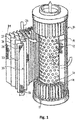
- a filter element is shown schematically, which is used, for example, in a hydraulic filter. Use in a hydraulic filter is particularly preferred. It is possible to use the filter element in other filters. It comprises a perforated frame or a cylindrical support tube 12 through which a plurality of flow openings 13 pass in the radial direction. In the circumferential direction, the support tube 12 is surrounded by a multilayer filter bellows 15, which in FIG Fig. 1 for clarity is partially shown in the manner of an exploded view.
- the filter bellows 15 can also be referred to as a corrugated or folded flat material.
- the filter bellows 15 is folded in a star shape by folds 17 running parallel to the longitudinal axis of the support tube 12 in such a way that fold tips 18 lying radially outside and bottoms 19 lying radially inside alternately follow one another along its circumference.
- the filter bellows 15 specifically has a three-layer filter material 22 with a fine filter layer in the form of a fleece 24, which is covered on the raw side by a pre-filter fleece 27 and on the clean side by a protective fleece 28 in the flow direction 26, i.e. in the illustrated embodiment in the radial direction from the outside to the inside .
- the fleeces can for example be made of a plastic or fiberglass material.
- the invention is not restricted to such a filter material, but is also suitable for other filter materials which are intended for filtration, for example with more or less than three layers.
- the filter material 22 is supported on the clean side on a support fabric 30, which lies flat against the protective fleece 28 of the filter material 22 and is also folded in a star shape.
- the support fabric 30 in turn is supported in the flow direction 26 in the area of the fold bases 19 on the support tube 12.
- a protective fabric 31 is arranged which lies flat against the pre-filter fleece 27 of the filter material 22 and is also folded in a star shape.
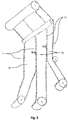
- the support fabric 30 and the protective fabric 31 are each made of a fabric layer according to the embodiment of the invention, which is based on Fig. 2 is explained in more detail. It is possible that only the support fabric 30 or only the protective fabric 31 are made from the fabric layer described in more detail below.
- the fabric layer according to the exemplary embodiment according to the invention has a first fabric strip 10.
- the first fabric strip 10 can also be referred to as the main fabric.
- the main fabric is characterized in that it enables the main function of the filter element, namely the flow through the filter material 22 required for the filtration.
- the first fabric strip 10 therefore has a particularly large effective area.
- the first fabric strip 10 extends in the longitudinal direction of the fabric layer according to FIG Fig. 2 . In the assembled state, ie in the filter element, the first fabric strip 10 extends in the circumferential direction of the filter element.
- first and second fabric strips 10, 11 can be provided.
- first fabric strips 10 and four second fabric strips 11 are provided, the first fabric strips 10 each extending between two second fabric strips 11.
- the entire fabric layer is cut so that partial fabric layers are created which each have a first fabric strip 10 and two second fabric strips 11 which extend along the edges of the fabric layer.
- the edges of the partial fabric layers form the front edges of the bellows 15, as in FIG Fig. 1 to see.
- three partial fabric layers are formed.
- the width of the partial fabric layers can differ. The width depends on the distance between the second fabric strips 11 from one another. This has the advantage that the fabric layer can be tailored for different filter bellows sizes.
- the main fabric that is to say the first fabric strip 10
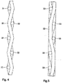
- the first fabric strip 10 is produced in the "twill weave” type of weave.
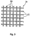
- the second fabric strips 11 are each produced in the type of weave "plain weave”.
- the first type of weave of the first fabric strip 10 can specifically have a twill weave or a herringbone twill weave. It is also possible that the first type of weave comprises a satin weave.
- the second type of weave can be plain weave or plain weave, as in Fig. 2 , or a leno weave. These second types of weave are characterized by the fact that they fix the warp threads well in the fabric layer (fixation weave).
- the fabric layer is not consistently woven in one and the same type of weave, for example in a twill weave, as in the prior art. Rather, at the points where the fabric layer is cut later, i. H. Woven on defined widths, each with a strip with a certain number of warp threads in a different type of weave, in particular in linen weave or linen weave.
- the main advantage is that the plain weave at the edge of the edge thread by the more frequent change, i. H. the more frequent cranking of the thread, is fixed much better in the fabric than with a pure twill weave. As a result, the edge thread tends to be much less likely to jump out of the fabric or to be pulled out.
- the filter element in addition to the fabric layer, is claimed with a filter bellows in which at least one fabric layer is integrated according to the exemplary embodiment according to the invention.
- the filter bellows contains several layers of material that are folded together to form a star-shaped pattern.
- One or two of these layers consist of a body tissue that has a positive effect on the performance data and, in particular, the pressure loss of the filter element.
- the first fabric strip 10 is designed in this way.
- Additional zones or strips with a plain weave can also be introduced between the actual cutting lanes, for example to create more flexible options after weaving to be able to cut to different tape widths.
- the plain weave on the edge ie in the second fabric strip
- other types of weave that differ from the actual first type of weave of the fabric can also be used on the edge, which hold the edge thread in the fabric much better than the twill weave.
- the leno weave comes into question here, for example. The manual reworking by jumping out of the edge threads is no longer necessary, which results in a significant improvement in production for the filter element production.
Landscapes
- Chemical & Material Sciences (AREA)
- Chemical Kinetics & Catalysis (AREA)
- Engineering & Computer Science (AREA)
- Textile Engineering (AREA)
- Inorganic Chemistry (AREA)
- Filtering Materials (AREA)
Applications Claiming Priority (2)
| Application Number | Priority Date | Filing Date | Title |
|---|---|---|---|
| DE202019102088.1U DE202019102088U1 (de) | 2019-04-11 | 2019-04-11 | Gewebelage, Flachmaterial, Filterelement und Filter |
| DE102019109617.0A DE102019109617B3 (de) | 2019-04-11 | 2019-04-11 | Gewebelage, Flachmaterial, Filterelement, Filter und Verfahren zur Herstellung einer Gewebelage |
Publications (2)
| Publication Number | Publication Date |
|---|---|
| EP3721964A1 true EP3721964A1 (fr) | 2020-10-14 |
| EP3721964B1 EP3721964B1 (fr) | 2026-04-29 |
Family
ID=72018365
Family Applications (1)
| Application Number | Title | Priority Date | Filing Date |
|---|---|---|---|
| EP19195274.6A Active EP3721964B1 (fr) | 2019-04-11 | 2019-09-04 | Matériau plat, élément filtrant, filtre et procédé de fabrication d'un matériau plat |
Country Status (3)
| Country | Link |
|---|---|
| US (2) | US11358075B2 (fr) |
| EP (1) | EP3721964B1 (fr) |
| CN (2) | CN111809288B (fr) |
Families Citing this family (1)
| Publication number | Priority date | Publication date | Assignee | Title |
|---|---|---|---|---|
| US11358075B2 (en) * | 2019-04-11 | 2022-06-14 | Argo-Hytos Group Ag | Fabric layer, flat material, filter element, filter and method for the production of a fabric layer |
Citations (2)
| Publication number | Priority date | Publication date | Assignee | Title |
|---|---|---|---|---|
| WO2009026978A2 (fr) | 2007-08-24 | 2009-03-05 | Fsp Fluid Systems Partners Holding Ag | Matériau plat ondulé ou plissé |
| DE102010025218A1 (de) * | 2010-06-23 | 2011-12-29 | Hydac Filtertechnik Gmbh | Filtermaterial für Fluide |
Family Cites Families (10)
| Publication number | Priority date | Publication date | Assignee | Title |
|---|---|---|---|---|
| US2365766A (en) * | 1939-04-10 | 1944-12-26 | Oscar H Levier | Oil filter |
| PL161586B1 (pl) * | 1990-01-04 | 1993-07-30 | Inst Inzynierii Materialow Wlo | Koszulka filtracyjna PL |
| US5713399A (en) * | 1997-02-07 | 1998-02-03 | Albany International Corp. | Ultrasonic seaming of abutting strips for paper machine clothing |
| US20140034580A1 (en) * | 2010-04-22 | 2014-02-06 | Kaydon Custom Filtration Corporation | Apparatus and method for removing contaminants from industrial fluid |
| US10060054B2 (en) * | 2014-05-09 | 2018-08-28 | The North Face Apparel Corp. | Unitary woven fabric construct of multiple zones |
| DE102014117506A1 (de) * | 2014-11-28 | 2016-06-02 | Filta Co., Ltd | Filtermedium mit großem Faltenabstand |
| CN204509608U (zh) | 2015-03-25 | 2015-07-29 | 浙江恒泰网业有限公司 | 一种凸条过滤网布 |
| CN107613799A (zh) | 2015-06-02 | 2018-01-19 | Gsm(运营)有限公司 | 特别适用于水上活动的衣物 |
| CN109440273A (zh) * | 2018-11-28 | 2019-03-08 | 泰安三英新材料有限公司 | 一种无机纤维织物热熔胶线固结装置及操作方法 |
| US11358075B2 (en) * | 2019-04-11 | 2022-06-14 | Argo-Hytos Group Ag | Fabric layer, flat material, filter element, filter and method for the production of a fabric layer |
-
2019
- 2019-08-23 US US16/549,366 patent/US11358075B2/en active Active
- 2019-09-04 EP EP19195274.6A patent/EP3721964B1/fr active Active
- 2019-10-09 CN CN201910955511.1A patent/CN111809288B/zh active Active
- 2019-10-09 CN CN201921683701.4U patent/CN211284735U/zh not_active Expired - Fee Related
-
2022
- 2022-05-13 US US17/663,301 patent/US12226718B2/en active Active
Patent Citations (2)
| Publication number | Priority date | Publication date | Assignee | Title |
|---|---|---|---|---|
| WO2009026978A2 (fr) | 2007-08-24 | 2009-03-05 | Fsp Fluid Systems Partners Holding Ag | Matériau plat ondulé ou plissé |
| DE102010025218A1 (de) * | 2010-06-23 | 2011-12-29 | Hydac Filtertechnik Gmbh | Filtermaterial für Fluide |
Also Published As
| Publication number | Publication date |
|---|---|
| US11358075B2 (en) | 2022-06-14 |
| US20200324228A1 (en) | 2020-10-15 |
| EP3721964B1 (fr) | 2026-04-29 |
| CN111809288A (zh) | 2020-10-23 |
| US12226718B2 (en) | 2025-02-18 |
| CN211284735U (zh) | 2020-08-18 |
| CN111809288B (zh) | 2022-11-29 |
| US20220288509A1 (en) | 2022-09-15 |
Similar Documents
| Publication | Publication Date | Title |
|---|---|---|
| EP2180931B1 (fr) | Matériau plat ondulé ou plissé | |
| EP0261488B1 (fr) | Feutre pour papeterie et son procédé de fabrication | |
| EP1525041A1 (fr) | Element de filtrage et procede de fabrication | |
| DE3337517A1 (de) | Filterelement und verfahren zu seiner herstellung | |
| EP3721964A1 (fr) | Couche tissée, matériau plat, élément filtrant, filtre et procédé de fabrication d'une couche tissée | |
| EP3698861A1 (fr) | Dispositif filtrant | |
| EP2945722B1 (fr) | Matériau de filtration | |
| EP1418261B1 (fr) | Tissu de fils métalliques | |
| DE2209928A1 (de) | Dreidimensionales gewebe und verfahren zu dessen herstellung | |
| DE102019109617B3 (de) | Gewebelage, Flachmaterial, Filterelement, Filter und Verfahren zur Herstellung einer Gewebelage | |
| DE202019102088U1 (de) | Gewebelage, Flachmaterial, Filterelement und Filter | |
| DE102017127057B4 (de) | Verbundfilter | |
| EP3454970B1 (fr) | Filtre plissé avec element de structuration | |
| WO2019007561A1 (fr) | Habillage et procédé de fabrication pour ledit habillage | |
| EP1412571A1 (fr) | Sangle tissee pour machine de collage de carton ondule | |
| EP3475481B1 (fr) | Toile pour une machine de fabrication d'une bande de matériau fibreux et procédé de fabrication d'une telle toile | |
| DE102020113073A1 (de) | Bespannung und Herstellverfahren für eine solche Bespannung | |
| DE102023201391B4 (de) | Ringfilterelement | |
| DE102016200320A1 (de) | Filtereinheit für Dunstabzugshaube | |
| DE102021122220B4 (de) | Webblatt und Verfahren zur Herstellung eines Webblatts | |
| DE102021122217B4 (de) | Webblatt und Verfahren zur Herstellung eines Webblatts | |
| DE20208865U1 (de) | Siebboden für eine Siebeinrichtung | |
| AT502437B1 (de) | Filterelement | |
| CH686420A5 (de) | Verfahren zur Herstellung einer,zur Vermeidung von Laufmaschen ausgebildeten Filterhulle eines Drainageelementes. | |
| DE4419104C2 (de) | Kerzenfilter mit schraubenförmiger Erhebung |
Legal Events
| Date | Code | Title | Description |
|---|---|---|---|
| PUAI | Public reference made under article 153(3) epc to a published international application that has entered the european phase |
Free format text: ORIGINAL CODE: 0009012 |
|
| STAA | Information on the status of an ep patent application or granted ep patent |
Free format text: STATUS: THE APPLICATION HAS BEEN PUBLISHED |
|
| AK | Designated contracting states |
Kind code of ref document: A1 Designated state(s): AL AT BE BG CH CY CZ DE DK EE ES FI FR GB GR HR HU IE IS IT LI LT LU LV MC MK MT NL NO PL PT RO RS SE SI SK SM TR |
|
| AX | Request for extension of the european patent |
Extension state: BA ME |
|
| STAA | Information on the status of an ep patent application or granted ep patent |
Free format text: STATUS: REQUEST FOR EXAMINATION WAS MADE |
|
| 17P | Request for examination filed |
Effective date: 20210312 |
|
| RBV | Designated contracting states (corrected) |
Designated state(s): AL AT BE BG CH CY CZ DE DK EE ES FI FR GB GR HR HU IE IS IT LI LT LU LV MC MK MT NL NO PL PT RO RS SE SI SK SM TR |
|
| RAP3 | Party data changed (applicant data changed or rights of an application transferred) |
Owner name: ARGO-HYTOS GROUP AG |
|
| STAA | Information on the status of an ep patent application or granted ep patent |
Free format text: STATUS: EXAMINATION IS IN PROGRESS |
|
| 17Q | First examination report despatched |
Effective date: 20220914 |
|
| P01 | Opt-out of the competence of the unified patent court (upc) registered |
Effective date: 20230613 |
|
| REG | Reference to a national code |
Ref country code: DE Ref legal event code: R079 Free format text: PREVIOUS MAIN CLASS: B01D0039080000 Ipc: D01D0013000000 Ref country code: DE Ref legal event code: R079 Ref document number: 502019014623 Country of ref document: DE Free format text: PREVIOUS MAIN CLASS: B01D0039080000 Ipc: D01D0013000000 |
|
| GRAP | Despatch of communication of intention to grant a patent |
Free format text: ORIGINAL CODE: EPIDOSNIGR1 |
|
| STAA | Information on the status of an ep patent application or granted ep patent |
Free format text: STATUS: GRANT OF PATENT IS INTENDED |
|
| RIC1 | Information provided on ipc code assigned before grant |
Ipc: D01D 13/00 20060101AFI20251105BHEP Ipc: B01D 39/08 20060101ALI20251105BHEP |
|
| GRAJ | Information related to disapproval of communication of intention to grant by the applicant or resumption of examination proceedings by the epo deleted |
Free format text: ORIGINAL CODE: EPIDOSDIGR1 |
|
| STAA | Information on the status of an ep patent application or granted ep patent |
Free format text: STATUS: EXAMINATION IS IN PROGRESS |
|
| INTG | Intention to grant announced |
Effective date: 20251126 |
|
| GRAP | Despatch of communication of intention to grant a patent |
Free format text: ORIGINAL CODE: EPIDOSNIGR1 |
|
| STAA | Information on the status of an ep patent application or granted ep patent |
Free format text: STATUS: GRANT OF PATENT IS INTENDED |
|
| INTC | Intention to grant announced (deleted) | ||
| INTG | Intention to grant announced |
Effective date: 20260126 |
|
| GRAS | Grant fee paid |
Free format text: ORIGINAL CODE: EPIDOSNIGR3 |
|
| GRAA | (expected) grant |
Free format text: ORIGINAL CODE: 0009210 |
|
| STAA | Information on the status of an ep patent application or granted ep patent |
Free format text: STATUS: THE PATENT HAS BEEN GRANTED |