EP3721973A1 - Dispositif et procédé de fabrication de fils laqués - Google Patents
Dispositif et procédé de fabrication de fils laqués Download PDFInfo
- Publication number
- EP3721973A1 EP3721973A1 EP19168503.1A EP19168503A EP3721973A1 EP 3721973 A1 EP3721973 A1 EP 3721973A1 EP 19168503 A EP19168503 A EP 19168503A EP 3721973 A1 EP3721973 A1 EP 3721973A1
- Authority
- EP
- European Patent Office
- Prior art keywords
- exhaust gas
- nozzle
- reducing agent
- pipe section
- nitrogen oxides
- Prior art date
- Legal status (The legal status is an assumption and is not a legal conclusion. Google has not performed a legal analysis and makes no representation as to the accuracy of the status listed.)
- Ceased
Links
Images


Classifications
-
- B—PERFORMING OPERATIONS; TRANSPORTING
- B01—PHYSICAL OR CHEMICAL PROCESSES OR APPARATUS IN GENERAL
- B01D—SEPARATION
- B01D53/00—Separation of gases or vapours; Recovering vapours of volatile solvents from gases; Chemical or biological purification of waste gases, e.g. engine exhaust gases, smoke, fumes, flue gases, aerosols
- B01D53/34—Chemical or biological purification of waste gases
- B01D53/74—General processes for purification of waste gases; Apparatus or devices specially adapted therefor
- B01D53/86—Catalytic processes
- B01D53/8621—Removing nitrogen compounds
- B01D53/8625—Nitrogen oxides
-
- H—ELECTRICITY
- H01—ELECTRIC ELEMENTS
- H01B—CABLES; CONDUCTORS; INSULATORS; SELECTION OF MATERIALS FOR THEIR CONDUCTIVE, INSULATING OR DIELECTRIC PROPERTIES
- H01B13/00—Apparatus or processes specially adapted for manufacturing conductors or cables
- H01B13/06—Insulating conductors or cables
- H01B13/065—Insulating conductors with lacquers or enamels
-
- B—PERFORMING OPERATIONS; TRANSPORTING
- B01—PHYSICAL OR CHEMICAL PROCESSES OR APPARATUS IN GENERAL
- B01D—SEPARATION
- B01D53/00—Separation of gases or vapours; Recovering vapours of volatile solvents from gases; Chemical or biological purification of waste gases, e.g. engine exhaust gases, smoke, fumes, flue gases, aerosols
- B01D53/34—Chemical or biological purification of waste gases
- B01D53/74—General processes for purification of waste gases; Apparatus or devices specially adapted therefor
- B01D53/86—Catalytic processes
- B01D53/90—Injecting reactants
-
- F—MECHANICAL ENGINEERING; LIGHTING; HEATING; WEAPONS; BLASTING
- F01—MACHINES OR ENGINES IN GENERAL; ENGINE PLANTS IN GENERAL; STEAM ENGINES
- F01N—GAS-FLOW SILENCERS OR EXHAUST APPARATUS FOR MACHINES OR ENGINES IN GENERAL; GAS-FLOW SILENCERS OR EXHAUST APPARATUS FOR INTERNAL-COMBUSTION ENGINES
- F01N3/00—Exhaust or silencing apparatus having means for purifying, rendering innocuous, or otherwise treating exhaust
- F01N3/08—Exhaust or silencing apparatus having means for purifying, rendering innocuous, or otherwise treating exhaust for rendering innocuous
- F01N3/10—Exhaust or silencing apparatus having means for purifying, rendering innocuous, or otherwise treating exhaust for rendering innocuous by thermal or catalytic conversion of noxious components of exhaust
- F01N3/18—Exhaust or silencing apparatus having means for purifying, rendering innocuous, or otherwise treating exhaust for rendering innocuous by thermal or catalytic conversion of noxious components of exhaust characterised by methods of operation; Control
- F01N3/20—Exhaust or silencing apparatus having means for purifying, rendering innocuous, or otherwise treating exhaust for rendering innocuous by thermal or catalytic conversion of noxious components of exhaust characterised by methods of operation; Control specially adapted for catalytic conversion
- F01N3/206—Adding periodically or continuously substances to exhaust gases for promoting purification, e.g. catalytic material in liquid form, NOx reducing agents
- F01N3/2066—Selective catalytic reduction [SCR]
-
- H—ELECTRICITY
- H01—ELECTRIC ELEMENTS
- H01B—CABLES; CONDUCTORS; INSULATORS; SELECTION OF MATERIALS FOR THEIR CONDUCTIVE, INSULATING OR DIELECTRIC PROPERTIES
- H01B13/00—Apparatus or processes specially adapted for manufacturing conductors or cables
- H01B13/0016—Apparatus or processes specially adapted for manufacturing conductors or cables for heat treatment
-
- H—ELECTRICITY
- H01—ELECTRIC ELEMENTS
- H01B—CABLES; CONDUCTORS; INSULATORS; SELECTION OF MATERIALS FOR THEIR CONDUCTIVE, INSULATING OR DIELECTRIC PROPERTIES
- H01B13/00—Apparatus or processes specially adapted for manufacturing conductors or cables
- H01B13/06—Insulating conductors or cables
- H01B13/16—Insulating conductors or cables by passing through or dipping in a liquid bath; by spraying
- H01B13/165—Insulating conductors or cables by passing through or dipping in a liquid bath; by spraying by spraying
-
- H—ELECTRICITY
- H01—ELECTRIC ELEMENTS
- H01B—CABLES; CONDUCTORS; INSULATORS; SELECTION OF MATERIALS FOR THEIR CONDUCTIVE, INSULATING OR DIELECTRIC PROPERTIES
- H01B13/00—Apparatus or processes specially adapted for manufacturing conductors or cables
- H01B13/30—Drying; Impregnating
-
- B—PERFORMING OPERATIONS; TRANSPORTING
- B01—PHYSICAL OR CHEMICAL PROCESSES OR APPARATUS IN GENERAL
- B01D—SEPARATION
- B01D2251/00—Reactants
- B01D2251/20—Reductants
- B01D2251/206—Ammonium compounds
- B01D2251/2067—Urea
-
- B—PERFORMING OPERATIONS; TRANSPORTING
- B01—PHYSICAL OR CHEMICAL PROCESSES OR APPARATUS IN GENERAL
- B01D—SEPARATION
- B01D2255/00—Catalysts
- B01D2255/10—Noble metals or compounds thereof
- B01D2255/102—Platinum group metals
- B01D2255/1021—Platinum
-
- B—PERFORMING OPERATIONS; TRANSPORTING
- B01—PHYSICAL OR CHEMICAL PROCESSES OR APPARATUS IN GENERAL
- B01D—SEPARATION
- B01D2255/00—Catalysts
- B01D2255/10—Noble metals or compounds thereof
- B01D2255/102—Platinum group metals
- B01D2255/1023—Palladium
-
- B—PERFORMING OPERATIONS; TRANSPORTING
- B01—PHYSICAL OR CHEMICAL PROCESSES OR APPARATUS IN GENERAL
- B01D—SEPARATION
- B01D2255/00—Catalysts
- B01D2255/20—Metals or compounds thereof
- B01D2255/207—Transition metals
- B01D2255/20707—Titanium
-
- B—PERFORMING OPERATIONS; TRANSPORTING
- B01—PHYSICAL OR CHEMICAL PROCESSES OR APPARATUS IN GENERAL
- B01D—SEPARATION
- B01D2255/00—Catalysts
- B01D2255/20—Metals or compounds thereof
- B01D2255/207—Transition metals
- B01D2255/20723—Vanadium
-
- B—PERFORMING OPERATIONS; TRANSPORTING
- B01—PHYSICAL OR CHEMICAL PROCESSES OR APPARATUS IN GENERAL
- B01D—SEPARATION
- B01D2255/00—Catalysts
- B01D2255/20—Metals or compounds thereof
- B01D2255/207—Transition metals
- B01D2255/20776—Tungsten
-
- B—PERFORMING OPERATIONS; TRANSPORTING
- B01—PHYSICAL OR CHEMICAL PROCESSES OR APPARATUS IN GENERAL
- B01D—SEPARATION
- B01D2255/00—Catalysts
- B01D2255/20—Metals or compounds thereof
- B01D2255/209—Other metals
- B01D2255/2092—Aluminium
-
- B—PERFORMING OPERATIONS; TRANSPORTING
- B01—PHYSICAL OR CHEMICAL PROCESSES OR APPARATUS IN GENERAL
- B01D—SEPARATION
- B01D2255/00—Catalysts
- B01D2255/90—Physical characteristics of catalysts
- B01D2255/904—Multiple catalysts
-
- B—PERFORMING OPERATIONS; TRANSPORTING
- B01—PHYSICAL OR CHEMICAL PROCESSES OR APPARATUS IN GENERAL
- B01D—SEPARATION
- B01D2257/00—Components to be removed
- B01D2257/50—Carbon oxides
- B01D2257/502—Carbon monoxide
-
- B—PERFORMING OPERATIONS; TRANSPORTING
- B01—PHYSICAL OR CHEMICAL PROCESSES OR APPARATUS IN GENERAL
- B01D—SEPARATION
- B01D2257/00—Components to be removed
- B01D2257/70—Organic compounds not provided for in groups B01D2257/00 - B01D2257/602
- B01D2257/702—Hydrocarbons
-
- B—PERFORMING OPERATIONS; TRANSPORTING
- B01—PHYSICAL OR CHEMICAL PROCESSES OR APPARATUS IN GENERAL
- B01D—SEPARATION
- B01D2257/00—Components to be removed
- B01D2257/70—Organic compounds not provided for in groups B01D2257/00 - B01D2257/602
- B01D2257/704—Solvents not covered by groups B01D2257/702 - B01D2257/7027
-
- B—PERFORMING OPERATIONS; TRANSPORTING
- B01—PHYSICAL OR CHEMICAL PROCESSES OR APPARATUS IN GENERAL
- B01D—SEPARATION
- B01D53/00—Separation of gases or vapours; Recovering vapours of volatile solvents from gases; Chemical or biological purification of waste gases, e.g. engine exhaust gases, smoke, fumes, flue gases, aerosols
- B01D53/34—Chemical or biological purification of waste gases
- B01D53/74—General processes for purification of waste gases; Apparatus or devices specially adapted therefor
- B01D53/86—Catalytic processes
- B01D53/8643—Removing mixtures of carbon monoxide or hydrocarbons and nitrogen oxides
- B01D53/8656—Successive elimination of the components
-
- B—PERFORMING OPERATIONS; TRANSPORTING
- B05—SPRAYING OR ATOMISING IN GENERAL; APPLYING FLUENT MATERIALS TO SURFACES, IN GENERAL
- B05D—PROCESSES FOR APPLYING FLUENT MATERIALS TO SURFACES, IN GENERAL
- B05D2401/00—Form of the coating product, e.g. solution, water dispersion, powders or the like
- B05D2401/10—Organic solvent
-
- B—PERFORMING OPERATIONS; TRANSPORTING
- B05—SPRAYING OR ATOMISING IN GENERAL; APPLYING FLUENT MATERIALS TO SURFACES, IN GENERAL
- B05D—PROCESSES FOR APPLYING FLUENT MATERIALS TO SURFACES, IN GENERAL
- B05D2505/00—Polyamides
-
- B—PERFORMING OPERATIONS; TRANSPORTING
- B05—SPRAYING OR ATOMISING IN GENERAL; APPLYING FLUENT MATERIALS TO SURFACES, IN GENERAL
- B05D—PROCESSES FOR APPLYING FLUENT MATERIALS TO SURFACES, IN GENERAL
- B05D3/00—Pretreatment of surfaces to which liquids or other fluent materials are to be applied; After-treatment of applied coatings, e.g. intermediate treating of an applied coating preparatory to subsequent applications of liquids or other fluent materials
- B05D3/04—Pretreatment of surfaces to which liquids or other fluent materials are to be applied; After-treatment of applied coatings, e.g. intermediate treating of an applied coating preparatory to subsequent applications of liquids or other fluent materials by exposure to gases
- B05D3/0406—Pretreatment of surfaces to which liquids or other fluent materials are to be applied; After-treatment of applied coatings, e.g. intermediate treating of an applied coating preparatory to subsequent applications of liquids or other fluent materials by exposure to gases the gas being air
-
- B—PERFORMING OPERATIONS; TRANSPORTING
- B05—SPRAYING OR ATOMISING IN GENERAL; APPLYING FLUENT MATERIALS TO SURFACES, IN GENERAL
- B05D—PROCESSES FOR APPLYING FLUENT MATERIALS TO SURFACES, IN GENERAL
- B05D7/00—Processes, other than flocking, specially adapted for applying liquids or other fluent materials to particular surfaces or for applying particular liquids or other fluent materials
- B05D7/20—Processes, other than flocking, specially adapted for applying liquids or other fluent materials to particular surfaces or for applying particular liquids or other fluent materials to wires
-
- F—MECHANICAL ENGINEERING; LIGHTING; HEATING; WEAPONS; BLASTING
- F01—MACHINES OR ENGINES IN GENERAL; ENGINE PLANTS IN GENERAL; STEAM ENGINES
- F01N—GAS-FLOW SILENCERS OR EXHAUST APPARATUS FOR MACHINES OR ENGINES IN GENERAL; GAS-FLOW SILENCERS OR EXHAUST APPARATUS FOR INTERNAL-COMBUSTION ENGINES
- F01N2570/00—Exhaust treating apparatus eliminating, absorbing or adsorbing specific elements or compounds
- F01N2570/14—Nitrogen oxides
-
- F—MECHANICAL ENGINEERING; LIGHTING; HEATING; WEAPONS; BLASTING
- F01—MACHINES OR ENGINES IN GENERAL; ENGINE PLANTS IN GENERAL; STEAM ENGINES
- F01N—GAS-FLOW SILENCERS OR EXHAUST APPARATUS FOR MACHINES OR ENGINES IN GENERAL; GAS-FLOW SILENCERS OR EXHAUST APPARATUS FOR INTERNAL-COMBUSTION ENGINES
- F01N2610/00—Adding substances to exhaust gases
- F01N2610/02—Adding substances to exhaust gases the substance being ammonia or urea
Definitions
- the invention relates to a device for producing enamelled wires, with an application device for applying at least one lacquer layer, an oven for solidifying the lacquer layer and with an exhaust gas purification device for removing at least nitrogen oxides from an exhaust gas of the furnace, the exhaust gas purification device being a system for the selective catalytic reduction of Nitrogen oxides in the exhaust gas of the furnace and a supply device for supplying a reducing agent, preferably an ammonia-containing compound, in particular urea solution, into the exhaust gas of the furnace.
- a reducing agent preferably an ammonia-containing compound, in particular urea solution
- the invention further relates to a method for producing enameled wires, at least one enamel layer being applied to a metal wire, which is solidified in an oven, an exhaust gas from the oven being at least freed from nitrogen oxides, the exhaust gas from the oven being subjected to selective catalytic reduction is subjected to nitrogen oxides, a reducing agent, preferably an ammonia-containing compound, in particular a urea solution, being fed to the exhaust gas via a feed device.
- a reducing agent preferably an ammonia-containing compound, in particular a urea solution
- Such a device or such a method for producing enameled wires with a forced-air oven for drying and curing enamel layers applied to the wire is known from the prior art.
- the exhaust gas from the convection oven which contains nitrogen oxides (NO x ) such as nitrogen monoxide (NO) and nitrogen dioxide (NO 2 ) as a result of the process, is passed through an exhaust gas cleaning device which has a system for selective catalytic reduction.
- the system has denitrification catalytic converters and an oxidation catalytic converter downstream of the denitrification catalytic converters.
- an atomizing nozzle protrudes perpendicular to the flow direction of the exhaust gas into a straight, tubular housing in which the exhaust gas is transported to the catalytic converters.
- a reducing agent containing urea is injected into the exhaust gas via the atomizing nozzle in a direction perpendicular to the flow direction of the exhaust gas.
- the urea in the exhaust gas is converted to ammonia (NH 3 ) with the help of thermolysis and hydrolysis, with the ammonia reducing the nitrogen oxides to nitrogen (N 2 ) and water (H 2 O) in the denitrification catalytic converters is used.
- the disadvantage here is that, due to the injection, the injected reducing agent can form a film on an inner surface of the tubular housing.
- Another disadvantage is that the reducing agent is not optimally mixed with the exhaust gas and thus urea is not completely thermolysed and hydrolysed, so that solid urea can be deposited in the area of the injection and / or in the denitrification catalysts.
- the object of the present invention is to alleviate or remedy at least some of the disadvantages of known systems for producing enamelled wires.
- the invention aims in particular to improve the mixing of the reducing agent introduced with the exhaust gas.
- the present invention provides a device for the production of enameled wires available, with an application device for applying at least one paint layer, a furnace for solidifying the paint layer and with an exhaust gas purification device for removing at least nitrogen oxides from an exhaust gas of the furnace, the exhaust gas purification device having a system for selective catalytic reduction of nitrogen oxides in the exhaust gas of the furnace and a supply device for supplying a reducing agent, preferably an ammonia-containing compound, in particular urea solution, into the exhaust gas of the furnace, the supply device having at least one outlet opening which is designed such that the reducing agent in the Exits from the outlet opening essentially in the flow direction of the exhaust gas.
- a reducing agent preferably an ammonia-containing compound, in particular urea solution
- the invention also provides a method for the production of enamelled wires available, wherein at least one enamel layer is applied to a metal wire, which is solidified in a furnace, wherein an exhaust gas from the furnace is at least freed of nitrogen oxides, the exhaust gas from the furnace a is subjected to selective catalytic reduction of nitrogen oxides, wherein a reducing agent, preferably an ammonia-containing compound, in particular a urea solution, is supplied to the exhaust gas via a supply device, the reducing agent being introduced essentially in the flow direction of the exhaust gas.
- a reducing agent preferably an ammonia-containing compound, in particular a urea solution
- film formation and deposits of the reducing agent can be reduced.
- the reducing agent introduced via the outlet opening essentially in the flow direction of the exhaust gas minimizes the transport of the reducing agent perpendicular to the flow direction of the exhaust gas in the direction of an edge of the exhaust gas flow, so that deposits on walls within which the exhaust gas is routed is reduced.
- the reducing agent can be introduced homogeneously into the exhaust gas, so that the reducing agent is distributed relatively homogeneously in the flow cross section of the exhaust gas.
- the reducing agent is introduced into the flowing exhaust gas using the direct current principle, so that the reducing agent flows in essentially the same direction as the exhaust gas into which the reducing agent is introduced when it emerges from the outlet opening.
- part of the feed device is arranged in a bent pipe section, the bent pipe section having a curvature between 60 and 150 °, preferably between 75 and 120 °, particularly preferably between 80 and 100 °, in particular essentially 90 °.
- a part of the supply device, around which the exhaust gas flows and which supplies the reducing agent to the exhaust gas can be designed without changes in direction, so that the cross section of the supply device is reduced transversely to the flow direction of the exhaust gas and thus the flow resistance of the exhaust gas through the supply device.
- cleaning of the feed device is simpler because foreign particles and / or urea, which can collect at the outlet opening or in the feed device, can be cleaned easily via an external access.
- the feed device does not have any risk zones in this section, such as kinks, corners, protruding edges, joints, welds or dead zones with eddies, where deposits can already occur when the reducing agent is fed in.
- a further advantage of the straight design of the part of the feed device around which the exhaust gas flows is the significantly simpler and more economical manufacture of the feed device.
- the part of the feed device arranged in the bent pipe section, apart from the outlet opening, is encased by a protective pipe.
- the feed device is shielded from the flowing exhaust gas, so that condensation of, for example, paint residues on cool points of the feed device can be reduced or prevented.
- the protective tube extends in the flow direction of the exhaust gas essentially as far as the outlet opening.
- the outlet opening is thereby advantageously completely enveloped by the protective tube and is thus protected from high temperatures or flow influences of the exhaust gas flowing past, such as, for example, shear flows of the exhaust gas.
- the feed device has a feed line with the at least one outlet opening, the outlet opening having a nozzle which is oriented essentially in the flow direction of the exhaust gas for injecting the reducing agent, essentially in the flow direction of the exhaust gas.
- the feed line is preferably a nozzle lance.
- the nozzle of the outlet opening is an atomizing nozzle for dividing the reducing agent, in particular into fine droplets.
- the reducing agent can thus advantageously be injected into the exhaust gas in finely divided form in the form of a spray in order to avoid liquid components of the reducing agent to evaporate them quickly.
- the atomizing nozzle is a two-substance nozzle which has an inner nozzle chamber and an outer nozzle chamber, the inner nozzle chamber being for supplying a first medium, the first medium containing the reducing agent, preferably the ammonia-containing compound, in particular the urea solution, the Outer nozzle chamber for supplying a second medium, preferably compressed air.
- the reducing agent can be injected into the exhaust gas with the aid of compressed air in order to enable the reducing agent to be finely distributed in the exhaust gas.
- the pressure of the compressed air is preferably between 1 and 20 bar, particularly preferably between 3 and 12 bar, in particular between 5 and 7 bar.
- smaller opening angles of the spray are possible with the two-substance nozzle, so that the transport of the reducing agent when injecting into the exhaust gas to the boundary area of the exhaust gas flow is reduced or avoided.
- the two-substance nozzle is an externally mixing two-substance nozzle which has a mixing chamber, the nozzle inner chamber and the nozzle outer chamber being connected separately to the nozzle outlet for the separate exit of the first medium and the second medium, preferably the compressed air, from the two-substance nozzle.
- External mixing in this context means that the reducing agent is only guided into the flow of the second medium, which is used for atomization, at the nozzle outlet by negative pressure or gravity and is atomized there.
- the two-fluid nozzle advantageously has a tube-in-tube system in which an inner tube transports the first medium to the nozzle inner chamber and an outer tube arranged coaxially around the inner tube transports the second medium to the nozzle outer chamber.
- the reducing agent in the first medium can be thermally sealed off from the exhaust gas by the second medium in order to avoid overheating of the nozzle.
- the first medium can contain a further compressed air in addition to the reducing agent.
- the two-substance nozzle is an internally mixing two-substance nozzle, the one Has nozzle outlet, wherein the nozzle inner chamber and the nozzle outer chamber are connected to the mixing chamber for mixing the first medium with the second medium, preferably the compressed air, in the mixing chamber.
- internal mixing means that the reducing agent and the second medium, which is used for atomization, are mixed in the mixing chamber before the nozzle exits. This enables a particularly fine spray to be generated.
- the exhaust gas cleaning device has a conical pipe section for the exhaust gas to flow through in the flow direction of the exhaust gas after the supply device and upstream of the system for the selective catalytic reduction of nitrogen oxides, the diameter of the conical pipe section increases in the direction of flow of the exhaust gas, the supplied reducing agent being introduced into the conical pipe section at least in sections.
- the reducing agent introduced can spread further in the radial direction relative to the flow of the exhaust gas without touching a wall that limits the exhaust gas flow.
- Another advantage is the increased residence time of the reducing agent in the exhaust gas due to the decreasing flow velocity of the exhaust gas, which is caused by the cross-sectional expansion.
- thermolysis and / or hydrolysis of the reducing agent to take place in the conical pipe section, so that a completely thermolyzed and / or hydrolysed reducing agent can be fed to the system for selective catalytic reduction downstream of the conical pipe section even at high metering rates of the reducing agent.
- the reducing agent introduced preferably the ammonia-containing compound introduced, in particular the urea solution introduced, is liquid and evaporates in the conical pipe section, ammonia being formed.
- a reducing agent introduced in liquid form can evaporate in the conical pipe section and thus a completely evaporated reducing agent can be supplied to the system for selective catalytic reduction downstream of the conical pipe section. This reduces or prevents film formation and deposits in the plant for selective catalytic reduction.
- the conical pipe section has a half opening angle between 1 and 10 °, preferably between 2 and 7 °, particularly preferably between 3 and 5 °, in particular essentially 4 °.
- the exhaust gas flow advantageously adapts to the course of the inner wall of the conical pipe section, so that the flow is prevented from becoming detached on the inner wall. This suppresses the formation of flow eddies which, although increasing the mixing of the reducing agent with the exhaust gas, can lead to an inhomogeneous distribution of the reducing agent in the exhaust gas.
- the system for selective catalytic reduction has at least one denitrification catalytic converter and at least one oxidation catalytic converter for breaking down carbon monoxide and / or hydrocarbons and / or ammonia, with preferably at least two, in particular exactly two, denitrification catalytic converters being provided one behind the other in the flow direction of the exhaust gas.
- This allows the reducing agent to convert the nitrogen oxides into nitrogen and water.
- ammonia formed from the reducing agent in the denitrification catalytic converters reacts catalytically with the nitrogen oxides in the exhaust gas to form nitrogen and water.
- pollutants such as carbon monoxide (CO) and unburned hydrocarbons (C m H n ) can react to form carbon dioxide (CO 2 ) and water.
- the at least one denitrification catalyst has a first coated metal carrier and a first washcoat and the oxidation catalyst has a second metal carrier and a second washcoat, the first washcoat preferably having oxides of titanium, vanadium and / or tungsten and the second washcoat platinum and / or has palladium.
- the coated metal carrier Due to the coated metal carrier, the at least one denitrification and the at least one oxidation catalyst are mechanically more stable than, for example, fully extruded ceramic catalysts, so that they can be used at higher temperatures and better protected against mechanical damage are protected during transport.
- the reaction area of the at least one denitrification or oxidation catalyst is advantageously increased by impressing the first or second washcoat on the first or second coated metal carrier, so that the efficiency of the chemical reactions occurring in the catalysts is increased.
- the flow rate of the exhaust gas and the concentrations of the nitrogen oxides in the exhaust gas are determined in the flow direction before the supply of the reducing agent and in the flow direction after the selective catalytic reduction, based on the determined flow rate of the exhaust gas and the determined concentrations of the nitrogen oxides in the exhaust gas
- Amount of the introduced reducing agent, preferably the introduced ammonia-containing compound, in particular the introduced urea solution, is determined.
- the stoichiometrically required amount of the introduced reducing agent, preferably the introduced ammonia-containing compound, in particular the introduced urea solution, for reducing the nitrogen oxides in the exhaust gas is determined based on the determined concentrations of the nitrogen oxides in the exhaust gas.
- the exact amount of reducing agent that is stoichiometrically required for the nitrogen oxides present in the exhaust gas is advantageously fed to the exhaust gas.
- a measured temperature of the exhaust gas and a measured dynamic pressure of the exhaust gas are advantageously taken into account to determine the mass flow of the exhaust gas for determining the required amount of reducing agent.
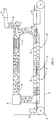
- Fig. 1 shows a device 1 for producing enameled wires 2.
- the apparatus 1 has an application device 3 for applying several layers of enamel to a metal wire.
- an oven 4 is provided for drying and curing the lacquer layers on the metal wire.
- the oven 4 has a drying zone 4 'and a curing zone 4 ".
- circulating air 5 is circulated by means of a fan 6.
- the circulating air 5 is enriched with various pollutants, as will be explained in detail below
- Oxidation catalytic converter 7 ' is provided and an exhaust gas purification system 7 for removing pollutants, in particular nitrogen oxides, from the exhaust gas of the furnace in a line carrying exhaust gases 9 Fig. 1 a cooler 8 for cooling the enamelled wire can be seen.
- the wire insulation is produced by drying and hardening the liquid lacquer layers applied to the wire in the convection oven 4 at approx. 550-700 ° C. Since the required final coating thickness must be applied in several passes, up to 24 covers of the same wire are fed through the drying or curing oven. During the drying of the liquid lacquer layers on the metal wire, lacquer solvents are evaporated at high temperature, which means that the circulating air of the lacquer wire system is continuously with it along the drying zone Solvent vapor saturates.
- the solvent nitrogen can also be increasingly oxidized to nitrogen oxides NO x (predominantly nitrogen monoxide NO, nitrogen dioxide NO 2 ) there.
- the mass flows of air and solvents introduced into the system are almost constant during production. Due to the process, a hot exhaust gas 9 is sucked off immediately after the circulating air catalytic converter and discharged into the environment.
- the exhaust gas is discharged through a steel pipe with an internal diameter of 80 mm by means of a radial fan.
- a vertically aligned countercurrent heat exchanger is usually flanged directly to the pipe outlet, which uses the thermal energy of the exhaust gas to generate water vapor as a protective and cleaning gas for the annealing process of the raw wire.
- the exhaust gas temperature is between 300 - 500 ° C before the evaporator and around 250 - 280 ° C after the evaporator.
- Relevant pollutant components in the system exhaust gas during the painting process are carbon monoxide CO, remaining volatile organic substances (hydrocarbons specified as total bound carbon or total C) and nitrogen oxides NO x .
- CO results from the incomplete combustion of the hydrocarbons.
- Remaining residual amounts of hydrocarbons in the furnace exhaust gas are due to the fact that the solvent vapors present are insufficiently oxidized in the circulating air process, especially in the circulating air catalytic converter 7 '. This can be caused by overloading, for example the process air with hydrocarbons (ie if too much solvent is introduced into the system), an insufficient temperature level in the circulating air catalytic converter or insufficient reactive oxygen (fresh air supply or exhaust gas volume) in the system.
- NO x in enamelled wire machines is what is known as fuel NO x and not thermal NO x .
- the formation of NO x in the painting process is largely based on the chemical conversion of the nitrogen content bound in the fuel (paint solvent) with atmospheric oxygen. Thermal NO x would arise from the nitrogen in the air at over 1000 ° C. However, experience has shown that higher temperatures promote the chemical conversion rate of N 2 to NO x (especially in the circulating air catalytic converter).
- One of the main sources of NO x in wire coating is the solvent NMP (N-methyl-2-pyrrolidone), which is the base solvent of the polyamideimide varnish (PAI) that is often used as an overcoat.
- NMP contains high amounts of nitrogen, which is oxidized to NO x in the furnace process, especially in high-temperature areas (e.g. heating zone, circulating air catalytic converter).
- exhaust gas quantities of approx. 65 - 70 Nm 3 / h are present.
- the exhaust gas contains remaining amounts of nitrogen monoxide NO, nitrogen dioxide NO 2 , carbon monoxide CO and remaining residual solvent components in the form of unburned hydrocarbons C n H m , which are to be actively cleaned off.
- the pollutant limit values for industrial exhaust gas are determined by various legal standards.
- Fig. 2 shows an exhaust gas purification device 7 according to the invention, which has a connecting element 10 for connecting the exhaust gas purification device 7 to the steel pipe of the furnace 4 provided for discharging the exhaust gas 9, a feed device 11, a conical pipe section 12 and a system 13 for selective catalytic reduction.
- the exhaust gas cleaning device 7 can be installed in any exhaust air pipe.
- the orientation of the exhaust gas cleaning device 7 can be horizontal or vertical. Since with a vertical orientation a difficult access to the exhaust gas cleaning device 7 for maintenance and If repairs are present, the horizontal alignment of the exhaust gas cleaning device 7 is preferred in horizontal systems for painting round wires.
- the exhaust gas 9 from the convection oven 4 is passed via a straight vertical pipe section 14 to a 90 ° bent pipe section 15 and then into the conical pipe section 12.
- the feed device 11 is arranged in one part, the feed device 11 having a feed line which, in the embodiment shown, is designed as a straight nozzle lance 16.
- the nozzle lance 16 is guided horizontally through a hole 17 in the bent pipe section 15, so that one end 18 of the nozzle lance 16 is arranged in a circular vertical cross-sectional area at the end of the bent pipe section 15 which is adjacent to the conical pipe section 12 and in which the flow of the exhaust gas 9 is aligned horizontally.
- the two-component nozzle 19 is arranged in the center of the circular vertical cross-sectional area at the end of the curved pipe section 15 which is adjacent to the conical pipe section 12, so that the nozzle outlet of the two-fluid nozzle 19 points to the center of the circular opening of the conical pipe section 12, which is adjacent to the curved pipe section 12 and coincides with the circular vertical cross-sectional area of the bent pipe section 12.
- the cross section of the conical pipe section 12 increases, so that the conical pipe section 12 has half an opening angle of 4 °.
- the conical pipe section 12 and the system 13 for selective catalytic reduction are thermally insulated with a 50 mm thick layer of mineral wool so that the exhaust gas 9 does not cool too much between the injection of the reducing agent and the system 13 for selective catalytic reduction.
- a reducing agent is injected into the exhaust gas via the two-substance nozzle 19 together with compressed air, wherein the spray 20 which forms during the injection protrudes into the conical pipe section 12. Since the nozzle outlet of the two-substance nozzle 19 points to the center of the circular opening of the conical pipe section 12, the reducing agent is injected in the form of fine droplets together with the compressed air essentially in the flow direction of the exhaust gas 9 in the middle of the flowing exhaust gas 9 in order to ensure a homogeneous mixing of the To achieve exhaust gas 9 with the reducing agent.
- an aqueous urea solution with a mass fraction of urea (NH 2 ) 2 CO of 32.5% is used as the reducing agent.
- This aqueous urea solution is known from the vehicle industry as "AdBlue”.
- the urea (NH 2 ) 2 CO is thermolyzed with the aid of the hot exhaust gas 9 to form ammonia NH 3 and isocyanic acid HNCO.
- the water H 2 O of the reducing agent evaporates completely and reacts with the isocyanic acid HNCO to form ammonia NH 3 and carbon dioxide CO 2 . Due to the homogeneous mixing with the exhaust gas 9 and the longer residence time in the conical pipe section 12 due to the decreasing flow velocity of the exhaust gas 9, the urea and isocyanic acid in the conical pipe section 12 are completely converted to vaporous ammonia.
- the conical pipe section 12 is followed by the system 13 for selective catalytic reduction, which has two denitrification catalytic converters 21 and one oxidation catalytic converter 22, in the flow direction of the exhaust gas.
- the denitrification catalytic converters 21 - also called SCR catalytic converters - are coated all-metal supports with a first metal support and a cell density of 300 cpsi. In contrast to ceramic products, metal supports are characterized by a significantly higher temperature resistance and mechanical resistance. This means that the SCR catalytic converter can also be used in enamelled wire ovens, where the exhaust air temperatures are much higher, up to 650 ° C.
- a first washcoat made of aluminum oxide with a very high specific surface area is stamped onto the first metal carrier and coated with the relevant oxides of titanium, vanadium and / or tungsten is.
- the applied first washcoat increases the reaction area of the denitrification catalysts 21 significantly, which increases the efficiency of the chemical reactions taking place.
- Particularly important with the coated metal catalytic converters is the lower storage capacity of ammonia, which allows the AdBlue metering to be readjusted much more quickly when the NO x loads in the system change.
- the evaporated ammonia NH 3 reacts with nitrogen monoxide NO and nitrogen dioxide NO 2 as well as oxygen O 2 from the exhaust gas 9 and the compressed air to form nitrogen N 2 and water vapor H 2 O.
- the oxidation catalytic converter 22 is arranged in the flow direction of the exhaust gas 9 and is a coated full metal carrier with a second metal carrier and a cell density of 300 cpsi.
- the applied second washcoat increases the reaction area of the oxidation catalytic converter 22 significantly, as a result of which the efficiency of the chemical reactions taking place is increased.
- the oxidation catalytic converter 22 remaining hydrocarbons C n H m and carbon monoxide CO in the exhaust gas 9 react to form carbon dioxide CO 2 and water vapor H 2 O.
- a first NO x sensor 23 for measuring the concentration of the nitrogen oxides in the exhaust gas 9 is arranged in the straight vertical pipe section 14 before the injection of the reducing agent. Furthermore, a second NO x sensor 24 for measuring the concentration of nitrogen oxides in the exhaust gas 9 is arranged after the oxidation catalytic converter 22 in the flow direction of the exhaust gas 9 after the system 13 for selective catalytic reduction.
- the nitrogen oxide concentrations measured with the aid of the first 23 and second 24 NO x sensors are used to calculate the amount of ammonia that is stoichiometrically required to reduce the concentration of nitrogen oxides in the exhaust gas 9 after the system 13 for selective catalytic reduction to one to reduce the legally prescribed target value.
- the NO x measurement with the first NO x sensor 23 is used to calculate the stoichiometric target injection amount of urea solution.
- the result of the chemical process is checked or the dosage of the urea solution is regulated accordingly.
- the mass flow and the temperature of the exhaust gas 9 are taken into account to calculate the stoichiometrically required amount of ammonia.
- the mass flow of the exhaust gas is determined, for example, with the aid of a dynamic pressure measured via a Prandtl tube or a differential pressure of the exhaust gas 9 measured via a venturi tube.
- the amount of ammonia stoichiometrically required for the conversion of the nitrogen oxides of the exhaust gas 9 is used to determine the amount of the urea or urea solution injected via the two-substance nozzle 19. Due to the parallel injection of the reducing agent into the exhaust gas 9, not only is the deposition due to wall film formation of the reducing agent minimized, but also a much finer signal of the current NO x output concentration or the current metered quantity with low oscillations and low amplitudes.
- Fig. 3 shows the bent pipe section 15 and the supply device 11 of the exhaust gas purification device 7 according to the invention Fig. 2 .
- the part of the feed device 11 which is arranged in the bent pipe section 15 is encased by a protective tube 25, which the nozzle lance 16 and the two-fluid nozzle 19 shields from the exhaust gas flowing through the bent pipe section 15.
- the protective tube prevents possible deposits of paint residue on the partly cool surface of the nozzle lance 16 and the two-substance nozzle 19 and also protects the entire two-substance nozzle 19 against the partially transversely flowing exhaust gas 9.
- the protective tube 25 extends in the direction of flow of the exhaust gas 9 up to the outlet opening.
- the protective tube 25 is welded to the bent pipe section and partially protrudes therefrom, a flange 26 being attached to the end of the protective pipe 25 arranged outside the bent pipe section 15.
- the flange 26 of the protective tube 25 is connected to a flange 28 fastened to the nozzle lance 16 with the aid of a clamping ring 27, so that the nozzle lance 16 and the two-substance nozzle 19 are fixed in the protective tube 25.
- the clamping ring 27 is loosened, the nozzle lance 16 with the two-substance nozzle 19 can be pulled out of the protective tube 25 for maintenance of the two-substance nozzle 19.
- the supply device 11 has a first line 29 for supplying the reducing agent and a second line 30 for supplying the compressed air with a standard pressure of 6 bar.
- the first line 29 guides the reducing agent from a pump (not shown) into an inner tube 31 which is arranged in the nozzle lance 16 and which guides the reducing agent to the two-substance nozzle 19.
- the second line 30 guides compressed air into an outer tube 32 which is arranged coaxially around the inner tube 31 and is arranged in the nozzle lance 16 and guides the compressed air to the two-substance nozzle 19.
- a branch 30a of the second line 30 is arranged, which leads to a compressed air inlet of the pump.
- the nozzle lance 16 has a compensator 32a, which can compensate for thermally caused different longitudinal expansions of the inner 31 and outer pipe 32.
- the temperature of the exhaust gas 9 is measured for control purposes, since the exhaust gas temperature should be between 220 and 550 ° C.
- Exhaust gas temperatures below 220 ° C inhibit the decomposition of urea into ammonia or can promote its crystallization.
- Exhaust gas temperatures above 550 ° C. for chemical reasons, require larger quantities of urea and can more easily lead to overheating of the two-substance nozzle 19.
- No reducing agent is injected outside the permissible temperature range between 220 and 550 ° C.
- a wire movement is checked via a winder signal, with no reducing agent being injected without a wire movement either.
- Fig. 4 shows a first embodiment of the two-substance nozzle 19, the two-substance nozzle 19 being designed as an externally mixing two-substance nozzle.
- the externally mixing two-substance nozzle has an inner nozzle chamber 33, an outer nozzle chamber 34 and a nozzle outlet 35 which is arranged in a nozzle cap 36.
- the inner tube 31 of the nozzle lance 16 carries a mixture of the reducing agent and a further compressed air to the inner nozzle chamber 33 of the outer mixing two-substance nozzle and the outer tube 32 of the nozzle lance 16 feeds the compressed air to the outer nozzle chamber 34, which is coaxially arranged around the inner nozzle chamber 33.
- the inner nozzle chamber 33 and the outer nozzle chamber 34 are separately connected to the nozzle outlet 35 so that the mixture of the reducing agent and the further compressed air exits the externally mixing two-substance nozzle separately from the compressed air.
- the nozzle cap 36 has a small depth, as a result of which the reducing agent is atomized directly at the nozzle outlet 35. This results in a significantly lower counterpressure in the second line 30 to the pump, so that a diaphragm pump, for example, can be used as the pump.
- the nozzle cap 36 of the external mixing two-substance nozzle can be unscrewed at any time and exchanged for another cap.
- Fig. 5 shows a second embodiment of the two-substance nozzle 19, the two-substance nozzle 19 being designed as an internally mixing two-substance nozzle.
- the internally mixing two-substance nozzle has an inner nozzle chamber 33, an outer nozzle chamber 34, a mixing chamber 37 and a nozzle outlet 35.
- the inner tube 31 of the nozzle lance 16 guides the reducing agent to the nozzle inner chamber 33 of the internally mixing two-substance nozzle and the outer tube 32 of the nozzle lance 16 carries the compressed air to the nozzle outer chamber 34, which is arranged coaxially around the nozzle inner chamber 33.
- the nozzle inner chamber 33 and the nozzle outer chamber 34 are connected to the mixing chamber 37 connected to the compressed air for mixing the reducing agent.
- the reducing agent mixed with the compressed air, emerges via the nozzle outlet 35 from the internally mixing two-substance nozzle.
- a pure reducing agent such as the aqueous urea solution
- an electric gear pump can build up the necessary pressure and the metering rate of the reducing agent, for example via a differential pressure measurement at the positions before and after a proportional valve of the gear pump are regulated.
Landscapes
- Engineering & Computer Science (AREA)
- Chemical & Material Sciences (AREA)
- Manufacturing & Machinery (AREA)
- Chemical Kinetics & Catalysis (AREA)
- Environmental & Geological Engineering (AREA)
- Health & Medical Sciences (AREA)
- Biomedical Technology (AREA)
- Analytical Chemistry (AREA)
- General Chemical & Material Sciences (AREA)
- Oil, Petroleum & Natural Gas (AREA)
- Toxicology (AREA)
- Combustion & Propulsion (AREA)
- Mechanical Engineering (AREA)
- General Engineering & Computer Science (AREA)
- Thermal Sciences (AREA)
- Physics & Mathematics (AREA)
- Exhaust Gas After Treatment (AREA)
- Exhaust Gas Treatment By Means Of Catalyst (AREA)
- Adornments (AREA)
Priority Applications (6)
| Application Number | Priority Date | Filing Date | Title |
|---|---|---|---|
| EP19168503.1A EP3721973A1 (fr) | 2019-04-10 | 2019-04-10 | Dispositif et procédé de fabrication de fils laqués |
| ES20716090T ES2948709T3 (es) | 2019-04-10 | 2020-04-09 | Dispositivo y procedimiento para la producción de alambres esmaltados |
| EP20716090.4A EP3953022B1 (fr) | 2019-04-10 | 2020-04-09 | Dispositif et procédé de fabrication de fils laqués |
| PCT/EP2020/060115 WO2020208125A1 (fr) | 2019-04-10 | 2020-04-09 | Dispositif et procédé de fabrication de fils vernis |
| CN202080027177.4A CN113660998B (zh) | 2019-04-10 | 2020-04-09 | 用于生产漆包线的装置和方法 |
| US17/602,006 US11605481B2 (en) | 2019-04-10 | 2020-04-09 | Device and method for producing enameled wires |
Applications Claiming Priority (1)
| Application Number | Priority Date | Filing Date | Title |
|---|---|---|---|
| EP19168503.1A EP3721973A1 (fr) | 2019-04-10 | 2019-04-10 | Dispositif et procédé de fabrication de fils laqués |
Publications (1)
| Publication Number | Publication Date |
|---|---|
| EP3721973A1 true EP3721973A1 (fr) | 2020-10-14 |
Family
ID=66105103
Family Applications (2)
| Application Number | Title | Priority Date | Filing Date |
|---|---|---|---|
| EP19168503.1A Ceased EP3721973A1 (fr) | 2019-04-10 | 2019-04-10 | Dispositif et procédé de fabrication de fils laqués |
| EP20716090.4A Active EP3953022B1 (fr) | 2019-04-10 | 2020-04-09 | Dispositif et procédé de fabrication de fils laqués |
Family Applications After (1)
| Application Number | Title | Priority Date | Filing Date |
|---|---|---|---|
| EP20716090.4A Active EP3953022B1 (fr) | 2019-04-10 | 2020-04-09 | Dispositif et procédé de fabrication de fils laqués |
Country Status (5)
| Country | Link |
|---|---|
| US (1) | US11605481B2 (fr) |
| EP (2) | EP3721973A1 (fr) |
| CN (1) | CN113660998B (fr) |
| ES (1) | ES2948709T3 (fr) |
| WO (1) | WO2020208125A1 (fr) |
Cited By (4)
| Publication number | Priority date | Publication date | Assignee | Title |
|---|---|---|---|---|
| CN112728567A (zh) * | 2020-12-25 | 2021-04-30 | 松田电工(台山)有限公司 | 一种漆包线烘焙炉废气处理方法及装置 |
| CN114937534A (zh) * | 2022-04-01 | 2022-08-23 | 卫辉市云波漆包线有限公司 | 一种节能环保的漆包机 |
| CN115155971A (zh) * | 2022-08-12 | 2022-10-11 | 河南鸿佑智能科技有限公司 | 一种用于架空裸导线的自动涂覆设备 |
| CN115201222A (zh) * | 2022-09-14 | 2022-10-18 | 苏州新镭激光科技有限公司 | 一种防磨损的漆包线检测设备 |
Families Citing this family (1)
| Publication number | Priority date | Publication date | Assignee | Title |
|---|---|---|---|---|
| CN120015428B (zh) * | 2025-04-18 | 2025-07-01 | 铜陵兢强电子科技股份有限公司 | 一种自调节型漆包圆线涂漆装置 |
Citations (5)
| Publication number | Priority date | Publication date | Assignee | Title |
|---|---|---|---|---|
| FR2120029A1 (fr) * | 1970-12-28 | 1972-08-11 | Universal Oil Prod Co | |
| DE102007055874A1 (de) * | 2006-12-20 | 2008-06-26 | Denso Corp., Kariya | Abgasemissionsteuerungsvorrichtung mit Additiveinspritzeinrichtung |
| EP2929927A1 (fr) * | 2014-04-07 | 2015-10-14 | P & F Maschinenbau GmbH | Procédé et dispositif destinés à la fabrication de fils vernis suivi de dénitrification de gaz |
| CN105427968A (zh) * | 2015-12-31 | 2016-03-23 | 无锡巨一同创科技有限公司 | 一种漆包机烘炉系统 |
| CN207499951U (zh) * | 2017-10-10 | 2018-06-15 | 广西玉柴机器股份有限公司 | 柴油机后处理系统 |
Family Cites Families (16)
| Publication number | Priority date | Publication date | Assignee | Title |
|---|---|---|---|---|
| US6167698B1 (en) * | 1999-12-21 | 2001-01-02 | Ford Motor Company | Exhaust gas purification system for a lean burn engine |
| JP3122133U (ja) * | 2006-03-23 | 2006-06-01 | 株式会社北斗興業 | 廃棄物処理システム |
| CN2912817Y (zh) * | 2006-04-07 | 2007-06-20 | 何旭润 | 两相流切割式内雾化喷枪 |
| US7497077B2 (en) * | 2006-07-26 | 2009-03-03 | Southwest Research Institute | System and method for dispensing an aqueous urea solution into an exhaust gas stream |
| WO2009070734A1 (fr) * | 2007-11-26 | 2009-06-04 | Michigan Technological University | Systèmes de contrôle de nox et procédés de contrôle des émissions de nox |
| CN201283268Y (zh) * | 2008-10-09 | 2009-08-05 | 江苏中科节能环保技术有限公司 | 选择性非催化还原法的喷嘴 |
| JP5558042B2 (ja) * | 2009-08-05 | 2014-07-23 | 三菱重工業株式会社 | 排ガス処理装置及び排ガスの水銀除去方法 |
| US10335776B2 (en) * | 2013-12-16 | 2019-07-02 | Basf Corporation | Manganese-containing diesel oxidation catalyst |
| DE102015016244A1 (de) * | 2015-12-16 | 2017-06-22 | Albonair Gmbh | Hitzeresistente Reduktionsmitteleinspritzdüse |
| GB2549716A (en) * | 2016-04-25 | 2017-11-01 | Gm Global Tech Operations Llc | A method for controlling an injector for injecting a reductant into an exhaust system of an internal combustion engine |
| GB201705289D0 (en) * | 2017-03-31 | 2017-05-17 | Johnson Matthey Catalysts (Germany) Gmbh | Selective catalytic reduction catalyst |
| BR112019024074A2 (pt) * | 2017-05-15 | 2020-06-02 | Basf Corporation | Composição de catalisador de oxidação, artigo catalítico, sistemas de tratamento de gases de escape e métodos para tratamento de uma corrente de gás de escape |
| CN110997138A (zh) * | 2017-06-09 | 2020-04-10 | 巴斯夫公司 | 用于NOx减排的具有受控孔隙率的催化洗涂层 |
| CN112638526B (zh) * | 2018-08-22 | 2024-01-05 | 巴斯夫公司 | 先进的nox还原催化剂 |
| US11008917B2 (en) * | 2018-08-24 | 2021-05-18 | International Engine Intellectual Property Company, Llc. | DEF dosing using multiple dosing locations while maintaining high passive soot oxidation |
| US10894237B2 (en) * | 2018-11-15 | 2021-01-19 | Caterpillar Inc. | Reductant nozzle with concave impinging surface |
-
2019
- 2019-04-10 EP EP19168503.1A patent/EP3721973A1/fr not_active Ceased
-
2020
- 2020-04-09 CN CN202080027177.4A patent/CN113660998B/zh active Active
- 2020-04-09 US US17/602,006 patent/US11605481B2/en active Active
- 2020-04-09 WO PCT/EP2020/060115 patent/WO2020208125A1/fr not_active Ceased
- 2020-04-09 ES ES20716090T patent/ES2948709T3/es active Active
- 2020-04-09 EP EP20716090.4A patent/EP3953022B1/fr active Active
Patent Citations (5)
| Publication number | Priority date | Publication date | Assignee | Title |
|---|---|---|---|---|
| FR2120029A1 (fr) * | 1970-12-28 | 1972-08-11 | Universal Oil Prod Co | |
| DE102007055874A1 (de) * | 2006-12-20 | 2008-06-26 | Denso Corp., Kariya | Abgasemissionsteuerungsvorrichtung mit Additiveinspritzeinrichtung |
| EP2929927A1 (fr) * | 2014-04-07 | 2015-10-14 | P & F Maschinenbau GmbH | Procédé et dispositif destinés à la fabrication de fils vernis suivi de dénitrification de gaz |
| CN105427968A (zh) * | 2015-12-31 | 2016-03-23 | 无锡巨一同创科技有限公司 | 一种漆包机烘炉系统 |
| CN207499951U (zh) * | 2017-10-10 | 2018-06-15 | 广西玉柴机器股份有限公司 | 柴油机后处理系统 |
Cited By (6)
| Publication number | Priority date | Publication date | Assignee | Title |
|---|---|---|---|---|
| CN112728567A (zh) * | 2020-12-25 | 2021-04-30 | 松田电工(台山)有限公司 | 一种漆包线烘焙炉废气处理方法及装置 |
| CN114937534A (zh) * | 2022-04-01 | 2022-08-23 | 卫辉市云波漆包线有限公司 | 一种节能环保的漆包机 |
| CN114937534B (zh) * | 2022-04-01 | 2023-05-05 | 卫辉市云波漆包线有限公司 | 一种节能环保的漆包机 |
| CN115155971A (zh) * | 2022-08-12 | 2022-10-11 | 河南鸿佑智能科技有限公司 | 一种用于架空裸导线的自动涂覆设备 |
| CN115155971B (zh) * | 2022-08-12 | 2023-07-07 | 河南鸿佑智能科技有限公司 | 一种用于架空裸导线的自动涂覆设备 |
| CN115201222A (zh) * | 2022-09-14 | 2022-10-18 | 苏州新镭激光科技有限公司 | 一种防磨损的漆包线检测设备 |
Also Published As
| Publication number | Publication date |
|---|---|
| EP3953022B1 (fr) | 2023-06-21 |
| EP3953022A1 (fr) | 2022-02-16 |
| CN113660998B (zh) | 2024-05-14 |
| CN113660998A (zh) | 2021-11-16 |
| US11605481B2 (en) | 2023-03-14 |
| EP3953022C0 (fr) | 2023-06-21 |
| US20220165455A1 (en) | 2022-05-26 |
| WO2020208125A1 (fr) | 2020-10-15 |
| ES2948709T3 (es) | 2023-09-18 |
Similar Documents
| Publication | Publication Date | Title |
|---|---|---|
| EP3953022B1 (fr) | Dispositif et procédé de fabrication de fils laqués | |
| EP0555746B1 (fr) | Dispositif pour la réduction catalytique de NOx | |
| EP2726414B1 (fr) | Générateur de gaz ammoniac et procédé pour produire de l'ammoniac pour la réduction d'oxydes d'azote dans des gaz de combustion | |
| DE602005000689T2 (de) | Einspritzdüse und Verfahren zur gleichmässigen Einspritzung eines Fluidstroms in einen Gasstrom mittels einer Einspritzdüse bei hoher Temperatur | |
| EP1956206B1 (fr) | Système de nettoyage des gaz d'échappement | |
| EP1969213A1 (fr) | Composant destine a etre monte dans le parcours des gaz d'echappement d'un moteur a combustion interne | |
| DE69318461T2 (de) | Verfahren und Vorrichtung zur Entfernung von Stickoxyden | |
| DE4203807A1 (de) | Vorrichtung zur katalytischen no(pfeil abwaerts)x(pfeil abwaerts)-reduktion | |
| EP2935105B1 (fr) | Générateur de gaz ammoniac et son utilisation pour la réduction d'oxydes d'azote dans les gaz d'échappement | |
| EP0615777A1 (fr) | Procédé et installation pour la réduction catalytique sélective de NOx des gaz d'échappement contenant d'oxygène | |
| DE102006038904A1 (de) | Verfahren zur Zugabe mindestens eines Reaktanden zu einem Abgasstrom und Vorrichtung zur Aufbereitung eines Abgasstroms einer Verbrennungskraftmaschine | |
| WO2015071233A1 (fr) | Système de post-traitement des gaz d'échappement | |
| EP3576864B1 (fr) | Procédé de traitement des effluents gazeux | |
| DE102015204294A1 (de) | Kompaktes selektives katalytisches Reduktionssystem für die Stickoxidreduktion in sauerstoffreichem Abgsas aus Brennkraftmaschinen von 500 bis 4500 kW | |
| EP2470759A1 (fr) | DISPOSITIF POUR LE NETTOYAGE DE GAZ D'ÉCHAPPEMENT CONTENANT DES NOX& xA; | |
| EP2929927B1 (fr) | Procédé et dispositif destinés à la fabrication de fils vernis suivi de dénitrification de gaz | |
| DE102016014966B4 (de) | Abgasnachbehandlungseinrichtung für einen Kraftwagen | |
| EP2166206B1 (fr) | Dispositif de dosage destiné au dosage d'un moyen de réduction, notamment pour une réduction catalytique sélective, dans un flux de gaz d'échappement d'un moteur à combustion interne | |
| DE102019006499A1 (de) | Beheizte Einpritzdüse | |
| DE102011106233A1 (de) | Verfahren zur Erzeugung von Ammoniak aus einer Ammoniakvorläufersubstanz zur Reduzierung von Stickoxiden in Abgasen | |
| DE102011106243A1 (de) | Ammoniakgasgenerator zur Erzeugung von Ammoniak zur Reduzierung von Stickoxiden in Abgasen | |
| DE102019200528B4 (de) | Verfahren zur Verhinderung einer Bildung von harnstoffbasierten Ablagerungen und Abgasstrang mit einer Beschichtung | |
| WO2006084570A1 (fr) | Dispositif pour delivrer une charge additive dans le conduit d'echappement d'un moteur a combustion interne | |
| DE202020100584U1 (de) | Zerstäuberdüse zum Eindüsen eines Reduktionsmittels in das Rauchgas einer Verbrennungsanlage | |
| DE102006027499A1 (de) | Abgasnachbehandlungseinrichtung einer Brennkraftmaschine |
Legal Events
| Date | Code | Title | Description |
|---|---|---|---|
| PUAI | Public reference made under article 153(3) epc to a published international application that has entered the european phase |
Free format text: ORIGINAL CODE: 0009012 |
|
| STAA | Information on the status of an ep patent application or granted ep patent |
Free format text: STATUS: THE APPLICATION HAS BEEN PUBLISHED |
|
| AK | Designated contracting states |
Kind code of ref document: A1 Designated state(s): AL AT BE BG CH CY CZ DE DK EE ES FI FR GB GR HR HU IE IS IT LI LT LU LV MC MK MT NL NO PL PT RO RS SE SI SK SM TR |
|
| AX | Request for extension of the european patent |
Extension state: BA ME |
|
| STAA | Information on the status of an ep patent application or granted ep patent |
Free format text: STATUS: THE APPLICATION HAS BEEN REFUSED |
|
| 18R | Application refused |
Effective date: 20201102 |