EP3722034A1 - Tangentialer frässchneideinsatz und fräswerkzeug - Google Patents
Tangentialer frässchneideinsatz und fräswerkzeug Download PDFInfo
- Publication number
- EP3722034A1 EP3722034A1 EP19168844.9A EP19168844A EP3722034A1 EP 3722034 A1 EP3722034 A1 EP 3722034A1 EP 19168844 A EP19168844 A EP 19168844A EP 3722034 A1 EP3722034 A1 EP 3722034A1
- Authority
- EP
- European Patent Office
- Prior art keywords
- minor
- axis
- major
- cutting insert
- reference plane
- Prior art date
- Legal status (The legal status is an assumption and is not a legal conclusion. Google has not performed a legal analysis and makes no representation as to the accuracy of the status listed.)
- Withdrawn
Links
Images



Classifications
-
- B—PERFORMING OPERATIONS; TRANSPORTING
- B23—MACHINE TOOLS; METAL-WORKING NOT OTHERWISE PROVIDED FOR
- B23C—MILLING
- B23C5/00—Milling-cutters
- B23C5/16—Milling-cutters characterised by physical features other than shape
- B23C5/20—Milling-cutters characterised by physical features other than shape with removable cutter bits or teeth or cutting inserts
- B23C5/202—Plate-like cutting inserts with special form
-
- B—PERFORMING OPERATIONS; TRANSPORTING
- B23—MACHINE TOOLS; METAL-WORKING NOT OTHERWISE PROVIDED FOR
- B23C—MILLING
- B23C5/00—Milling-cutters
- B23C5/02—Milling-cutters characterised by the shape of the cutter
- B23C5/06—Face-milling cutters, i.e. having only or primarily a substantially flat cutting surface
-
- B—PERFORMING OPERATIONS; TRANSPORTING
- B23—MACHINE TOOLS; METAL-WORKING NOT OTHERWISE PROVIDED FOR
- B23C—MILLING
- B23C2200/00—Details of milling cutting inserts
- B23C2200/04—Overall shape
- B23C2200/0416—Irregular
-
- B—PERFORMING OPERATIONS; TRANSPORTING
- B23—MACHINE TOOLS; METAL-WORKING NOT OTHERWISE PROVIDED FOR
- B23C—MILLING
- B23C2200/00—Details of milling cutting inserts
- B23C2200/16—Supporting or bottom surfaces
- B23C2200/161—Supporting or bottom surfaces with projections
-
- B—PERFORMING OPERATIONS; TRANSPORTING
- B23—MACHINE TOOLS; METAL-WORKING NOT OTHERWISE PROVIDED FOR
- B23C—MILLING
- B23C2200/00—Details of milling cutting inserts
- B23C2200/16—Supporting or bottom surfaces
- B23C2200/164—Supporting or bottom surfaces discontinuous
-
- B—PERFORMING OPERATIONS; TRANSPORTING
- B23—MACHINE TOOLS; METAL-WORKING NOT OTHERWISE PROVIDED FOR
- B23C—MILLING
- B23C2200/00—Details of milling cutting inserts
- B23C2200/16—Supporting or bottom surfaces
- B23C2200/168—Supporting or bottom surfaces with features related to indexing
-
- B—PERFORMING OPERATIONS; TRANSPORTING
- B23—MACHINE TOOLS; METAL-WORKING NOT OTHERWISE PROVIDED FOR
- B23C—MILLING
- B23C2200/00—Details of milling cutting inserts
- B23C2200/28—Angles
- B23C2200/284—Negative clearance angles
-
- B—PERFORMING OPERATIONS; TRANSPORTING
- B23—MACHINE TOOLS; METAL-WORKING NOT OTHERWISE PROVIDED FOR
- B23C—MILLING
- B23C2200/00—Details of milling cutting inserts
- B23C2200/36—Other features of the milling insert not covered by B23C2200/04 - B23C2200/32
- B23C2200/367—Mounted tangentially, i.e. where the rake face is not the face with largest area
-
- B—PERFORMING OPERATIONS; TRANSPORTING
- B23—MACHINE TOOLS; METAL-WORKING NOT OTHERWISE PROVIDED FOR
- B23C—MILLING
- B23C2210/00—Details of milling cutters
- B23C2210/16—Fixation of inserts or cutting bits in the tool
- B23C2210/168—Seats for cutting inserts, supports for replacable cutting bits
Definitions
- the bottom side has a first auxiliary stop surface distanced further from the first reference plane and arranged closer to the second major side surface than the first main abutment surface, the first auxiliary stop surface extending away from the first reference plane with increasing distance from the first main abutment surface.
- the first auxiliary stop surface provides additional failure prevention in a case where a fastener for fixing the milling cutting insert comes close to overload.
- the first auxiliary stop surface can be adapted to the insert seat of a milling tool such that it is non-contacting in normal operation and only contacts a corresponding surface of the seat when a fastener for fixing the milling cutting insert in the insert seat is elongated by acting centrifugal forces close to material failure.
- the first auxiliary stop surface can preferably extend away from the first reference plane at a steeper angle than the first main abutment surface, i.e. it is preferably inclined stronger than the first main abutment surface.
- the bottom surface has an inclined second main abutment surface extending away from the first reference plane with increasing distance from the second major side surface.
- a distance of the first major cutting edge from the first reference plane increases with increasing distance from the first cutting corner.
- the resulting cutting forces are particularly advantageous. Negative axial force acting on the milling cutting insert and consequently also on the base body during machining are reduced in this way. Consequently, the whole system achieves a high stability which is a key factor in high speed milling.
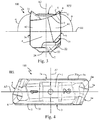
- the tangential milling cutting insert 100 has a top side 1, a bottom side 2, first and second major side surfaces 3, 3a extending between the top side 1 and the bottom side 2, and first and second minor side surfaces 4, 4a extending between the top side 1 and the bottom side 2.
- each of these surfaces has a plurality of sub-surfaces which will be described more in detail further below.
- a through-hole 8 for receiving a fastener extends through the tangential milling cutting insert 100 from the first major side surface 3 to the second major side surface 3a along a first axis A1.
- a second axis A2 extends orthogonal to the first axis A1 and extends through the top side 1 and the bottom side 2.
- the first minor cutting edge 7 is inclined towards the first reference plane RP1 with increasing distance from the first cutting corner 6, i.e. it comes closer to the first reference plane RP1 with increasing distance from the first cutting corner 6.
- the second minor cutting edge 7a is inclined towards the first reference plane RP1 with increasing distance from the second cutting corner 6a.
- the top side 1 serves as chip surface with regard to the first and second major cutting edges 5, 5a, the first and second cutting corners 6, 6a, and the first and second minor cutting edges 7, 7a.
- the top side 1 is provided with corresponding chip conduction structures.
- the second additional main abutment surface 22a is separated from the second min abutment surface 21a by a depression formed below the through-hole 8.
- the first main abutment surface 21 and the first additional main abutment surface 22 can be flat surfaces lying in a common plane.
- the second main abutment surface 21a and the second additional main abutment surface 22a are also formed as flat surfaces lying in a common plane.
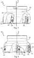
- the seats 202 are distributed about the circumference of the base body 201 such that the mounted tangential milling cutting inserts 100 protrude axially from the base body 201 with first minor cutting edges 7 and protrude radially from the base body 201 with first major cutting edges 5.
- the terms axially and radially are here used with reference to the rotational axis R of the milling tool 200.
- the seats 202 are arranged such that the mounted tangential milling cutting inserts 100 are all arranged with a similar orientation and only distributed at different angular positions in the circumferential direction.
- the seat 202 has a radial securing surface 204 against which the first main abutment surface 21 of the tangential milling cutting insert 100 rests in a mounted state. Further, the seat 202 has an additional radial securing surface 207 against which the first additional main abutment surface 22 of the tangential milling cutting insert 100 rests in a mounted state. As can be seen in Fig. 7 and Fig. 8 , the seat 202 has an axial support surface 205 against which the second minor abutment surface 42a of the second minor side surface 4a rests in a mounted state of the tangential milling cutting insert 100.
- An auxiliary securing surface 206 is further provided in the insert seat 202.
- the auxiliary securing surface 206 is arranged such that it extends at least regionally parallel to the first auxiliary stop surface 23 of the tangential milling cutting insert 100 in a mounted state but does not contact the first auxiliary stop surface 23 in a normal mounted state.
- the first auxiliary stop surface 23 will move against the auxiliary securing surface 206, thus preventing failure of the fastener 300.
- the side surfaces of the central protrusion 24 are tilted relative to the second reference plane RP2 and thus form even further securing elements by moving against further surfaces in the seat 202 in the case of abnormal elongation of the fastener 300 during high-speed machining.
Landscapes
- Engineering & Computer Science (AREA)
- Mechanical Engineering (AREA)
- Milling Processes (AREA)
Priority Applications (1)
| Application Number | Priority Date | Filing Date | Title |
|---|---|---|---|
| EP19168844.9A EP3722034A1 (de) | 2019-04-12 | 2019-04-12 | Tangentialer frässchneideinsatz und fräswerkzeug |
Applications Claiming Priority (1)
| Application Number | Priority Date | Filing Date | Title |
|---|---|---|---|
| EP19168844.9A EP3722034A1 (de) | 2019-04-12 | 2019-04-12 | Tangentialer frässchneideinsatz und fräswerkzeug |
Publications (1)
| Publication Number | Publication Date |
|---|---|
| EP3722034A1 true EP3722034A1 (de) | 2020-10-14 |
Family
ID=66175185
Family Applications (1)
| Application Number | Title | Priority Date | Filing Date |
|---|---|---|---|
| EP19168844.9A Withdrawn EP3722034A1 (de) | 2019-04-12 | 2019-04-12 | Tangentialer frässchneideinsatz und fräswerkzeug |
Country Status (1)
| Country | Link |
|---|---|
| EP (1) | EP3722034A1 (de) |
Citations (4)
| Publication number | Priority date | Publication date | Assignee | Title |
|---|---|---|---|---|
| EP1083017A1 (de) | 1999-09-09 | 2001-03-14 | Plansee Tizit Aktiengesellschaft | Rotierendes Zerspanungswerkzeug |
| EP2404690A1 (de) * | 2009-03-06 | 2012-01-11 | Mitsubishi Materials Corporation | Schneideeinsatz und werkzeug mit schneideeinsätzen |
| US20140234036A1 (en) * | 2013-02-19 | 2014-08-21 | Iscar, Ltd. | High Speed Milling Tool and Tangential Ramping Milling Insert Therefor |
| US20180272444A1 (en) * | 2017-03-22 | 2018-09-27 | Kennametal Inc. | Tangentially mounted cutting insert with angled seating surface and recessed clearance surface |
-
2019
- 2019-04-12 EP EP19168844.9A patent/EP3722034A1/de not_active Withdrawn
Patent Citations (4)
| Publication number | Priority date | Publication date | Assignee | Title |
|---|---|---|---|---|
| EP1083017A1 (de) | 1999-09-09 | 2001-03-14 | Plansee Tizit Aktiengesellschaft | Rotierendes Zerspanungswerkzeug |
| EP2404690A1 (de) * | 2009-03-06 | 2012-01-11 | Mitsubishi Materials Corporation | Schneideeinsatz und werkzeug mit schneideeinsätzen |
| US20140234036A1 (en) * | 2013-02-19 | 2014-08-21 | Iscar, Ltd. | High Speed Milling Tool and Tangential Ramping Milling Insert Therefor |
| US20180272444A1 (en) * | 2017-03-22 | 2018-09-27 | Kennametal Inc. | Tangentially mounted cutting insert with angled seating surface and recessed clearance surface |
Similar Documents
| Publication | Publication Date | Title |
|---|---|---|
| RU2743824C1 (ru) | Инструментальная система и способ токарной обработки | |
| USRE42644E1 (en) | Indexable cutting insert with chip breaker | |
| RU2304492C2 (ru) | Режущий инструмент и режущая пластина для него | |
| EP1093874B1 (de) | Werkzeugschneideinsatz mit negativen Schneidkanten zur spanabhebenden Bearbeitung | |
| US7520699B2 (en) | Cutting tool and cutting insert | |
| EP2638994B1 (de) | Schneideeinsatz und Grundkörper für Werkzeuge zur spanentfernenden Bearbeitung | |
| US8506208B2 (en) | Shim plate for milling tools for chip removing machining as well as a milling tool having such a shim plate | |
| US7121769B2 (en) | Rotary slot milling cutter and cutting insert therefor | |
| US5957629A (en) | Fine milling cutting insert | |
| US6102630A (en) | Ball nose end mill insert | |
| BG65121B1 (bg) | Тангенциална режеща вложка и челна фреза | |
| US7275895B2 (en) | Cutting insert | |
| US20210252615A1 (en) | Double-sided tangential milling cutting insert | |
| JP7405941B2 (ja) | フライス工具 | |
| EP3450069A1 (de) | Fräseinsatz und scheibenfräswerkzeug | |
| US5256009A (en) | Cutting insert for tools | |
| KR102817368B1 (ko) | 절삭 가공을 위한 공구 및 그에 대한 절삭 인서트의 사용 | |
| WO1998033615A1 (en) | Cutting inserts | |
| WO2024217726A1 (en) | Turning tool kit and cutting insert therefor |
Legal Events
| Date | Code | Title | Description |
|---|---|---|---|
| PUAI | Public reference made under article 153(3) epc to a published international application that has entered the european phase |
Free format text: ORIGINAL CODE: 0009012 |
|
| STAA | Information on the status of an ep patent application or granted ep patent |
Free format text: STATUS: THE APPLICATION HAS BEEN PUBLISHED |
|
| AK | Designated contracting states |
Kind code of ref document: A1 Designated state(s): AL AT BE BG CH CY CZ DE DK EE ES FI FR GB GR HR HU IE IS IT LI LT LU LV MC MK MT NL NO PL PT RO RS SE SI SK SM TR |
|
| AX | Request for extension of the european patent |
Extension state: BA ME |
|
| STAA | Information on the status of an ep patent application or granted ep patent |
Free format text: STATUS: REQUEST FOR EXAMINATION WAS MADE |
|
| 17P | Request for examination filed |
Effective date: 20210402 |
|
| RBV | Designated contracting states (corrected) |
Designated state(s): AL AT BE BG CH CY CZ DE DK EE ES FI FR GB GR HR HU IE IS IT LI LT LU LV MC MK MT NL NO PL PT RO RS SE SI SK SM TR |
|
| GRAP | Despatch of communication of intention to grant a patent |
Free format text: ORIGINAL CODE: EPIDOSNIGR1 |
|
| STAA | Information on the status of an ep patent application or granted ep patent |
Free format text: STATUS: GRANT OF PATENT IS INTENDED |
|
| INTG | Intention to grant announced |
Effective date: 20231120 |
|
| STAA | Information on the status of an ep patent application or granted ep patent |
Free format text: STATUS: THE APPLICATION IS DEEMED TO BE WITHDRAWN |
|
| 18D | Application deemed to be withdrawn |
Effective date: 20240321 |