EP3722041B1 - Dispositif de soudage par résistance et procédé de soudage par résistance permettant de souder par résistance au moins un composant - Google Patents
Dispositif de soudage par résistance et procédé de soudage par résistance permettant de souder par résistance au moins un composant Download PDFInfo
- Publication number
- EP3722041B1 EP3722041B1 EP20160830.4A EP20160830A EP3722041B1 EP 3722041 B1 EP3722041 B1 EP 3722041B1 EP 20160830 A EP20160830 A EP 20160830A EP 3722041 B1 EP3722041 B1 EP 3722041B1
- Authority
- EP
- European Patent Office
- Prior art keywords
- welding
- polarity
- transformer
- resistance welding
- resistance
- Prior art date
- Legal status (The legal status is an assumption and is not a legal conclusion. Google has not performed a legal analysis and makes no representation as to the accuracy of the status listed.)
- Active
Links
Images

Classifications
-
- B—PERFORMING OPERATIONS; TRANSPORTING
- B23—MACHINE TOOLS; METAL-WORKING NOT OTHERWISE PROVIDED FOR
- B23K—SOLDERING OR UNSOLDERING; WELDING; CLADDING OR PLATING BY SOLDERING OR WELDING; CUTTING BY APPLYING HEAT LOCALLY, e.g. FLAME CUTTING; WORKING BY LASER BEAM
- B23K11/00—Resistance welding; Severing by resistance heating
- B23K11/24—Electric supply or control circuits therefor
- B23K11/241—Electric supplies
-
- B—PERFORMING OPERATIONS; TRANSPORTING
- B23—MACHINE TOOLS; METAL-WORKING NOT OTHERWISE PROVIDED FOR
- B23K—SOLDERING OR UNSOLDERING; WELDING; CLADDING OR PLATING BY SOLDERING OR WELDING; CUTTING BY APPLYING HEAT LOCALLY, e.g. FLAME CUTTING; WORKING BY LASER BEAM
- B23K11/00—Resistance welding; Severing by resistance heating
- B23K11/36—Auxiliary equipment
-
- B—PERFORMING OPERATIONS; TRANSPORTING
- B23—MACHINE TOOLS; METAL-WORKING NOT OTHERWISE PROVIDED FOR
- B23K—SOLDERING OR UNSOLDERING; WELDING; CLADDING OR PLATING BY SOLDERING OR WELDING; CUTTING BY APPLYING HEAT LOCALLY, e.g. FLAME CUTTING; WORKING BY LASER BEAM
- B23K11/00—Resistance welding; Severing by resistance heating
- B23K11/16—Resistance welding; Severing by resistance heating taking account of the properties of the material to be welded
- B23K11/18—Resistance welding; Severing by resistance heating taking account of the properties of the material to be welded of non-ferrous metals
- B23K11/185—Resistance welding; Severing by resistance heating taking account of the properties of the material to be welded of non-ferrous metals of aluminium or aluminium alloys
-
- B—PERFORMING OPERATIONS; TRANSPORTING
- B23—MACHINE TOOLS; METAL-WORKING NOT OTHERWISE PROVIDED FOR
- B23K—SOLDERING OR UNSOLDERING; WELDING; CLADDING OR PLATING BY SOLDERING OR WELDING; CUTTING BY APPLYING HEAT LOCALLY, e.g. FLAME CUTTING; WORKING BY LASER BEAM
- B23K11/00—Resistance welding; Severing by resistance heating
- B23K11/24—Electric supply or control circuits therefor
- B23K11/25—Monitoring devices
- B23K11/252—Monitoring devices using digital means
- B23K11/258—Monitoring devices using digital means the measured parameter being a voltage
-
- B—PERFORMING OPERATIONS; TRANSPORTING
- B23—MACHINE TOOLS; METAL-WORKING NOT OTHERWISE PROVIDED FOR
- B23K—SOLDERING OR UNSOLDERING; WELDING; CLADDING OR PLATING BY SOLDERING OR WELDING; CUTTING BY APPLYING HEAT LOCALLY, e.g. FLAME CUTTING; WORKING BY LASER BEAM
- B23K2101/00—Articles made by soldering, welding or cutting
- B23K2101/006—Vehicles
-
- B—PERFORMING OPERATIONS; TRANSPORTING
- B23—MACHINE TOOLS; METAL-WORKING NOT OTHERWISE PROVIDED FOR
- B23K—SOLDERING OR UNSOLDERING; WELDING; CLADDING OR PLATING BY SOLDERING OR WELDING; CUTTING BY APPLYING HEAT LOCALLY, e.g. FLAME CUTTING; WORKING BY LASER BEAM
- B23K2101/00—Articles made by soldering, welding or cutting
- B23K2101/18—Sheet panels
-
- B—PERFORMING OPERATIONS; TRANSPORTING
- B23—MACHINE TOOLS; METAL-WORKING NOT OTHERWISE PROVIDED FOR
- B23K—SOLDERING OR UNSOLDERING; WELDING; CLADDING OR PLATING BY SOLDERING OR WELDING; CUTTING BY APPLYING HEAT LOCALLY, e.g. FLAME CUTTING; WORKING BY LASER BEAM
- B23K2103/00—Materials to be soldered, welded or cut
- B23K2103/08—Non-ferrous metals or alloys
- B23K2103/10—Aluminium or alloys thereof
Definitions
- the present invention relates to a resistance welding device and a resistance welding method for resistance welding of at least one component.
- Resistance welding of various sheet metal combinations is used, for example, in automated vehicle production, in which welding devices produce welded connections on, for example, a body of a vehicle, such as a motor vehicle, truck, aircraft, etc.
- welding devices produce welded connections on, for example, a body of a vehicle, such as a motor vehicle, truck, aircraft, etc.
- metallic parts are connected by welding using a welding tool of the welding device.
- a welding device in particular a resistance welding device, can also be used in individual production.
- WO 2013/063628 A1 shows a resistance welding device with a power source arranged on the welding gun and having a high-current transformer. Transistors are used on the secondary side of the transformer.
- EP 3 181 284 A1 relates to a power converter circuit for providing a high current, in particular an electrical current, such as is required for resistance welding.
- Transistors are arranged on the secondary side of a welding transformer.
- the welding transformer is preferably designed as a medium-frequency direct current transformer (MF-DC transformer) and is also referred to as a transformer rectifier unit.
- MF-DC transformer medium-frequency direct current transformer
- the disruptive magnetization effect that occurs with a conventional diode rectifier can be avoided very efficiently, inexpensively, cost-effectively and with a high degree of safety using the resistance welding device described.
- control device and the at least one welding transformer can be connected via at least one line in addition to a connection for the voltage that is to be applied to the primary side of the at least one welding transformer, wherein the control device is designed to transmit polarity information via the at least one line to the Send polarity switching module (35) for switching the polarity of the at least one welding transformer.
- the polarity switching device may be designed to always switch all at least two transformers connected in parallel to the same polarity.
- the welding tool is a welding gun with two welding electrodes, between which the at least one component is arranged during welding.
- the object is also achieved by a resistance welding method for resistance welding of at least one component according to claim 14.
- the resistance welding method is carried out with a resistance welding device which has a welding tool with at least one welding electrode, which is to be contacted for welding with the at least one component, at least one welding transformer for supplying an electrical current to the welding tool when welding the at least one component, a series connection of two Transistors between the welding tool and an output of the welding transformer are connected, and has a control device.
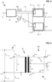
- the resistance welding device 2 has a welding tool 10 in the form of a welding gun with two welding electrodes 11, 12, a detection device 15, which is arranged on the welding tool 10 for detecting an electrode voltage U E , a welding controller or control device 20 with a converter connected to it 22 with an output 25, a welding transformer 30 with three outputs 31, 32, 33 and an evaluation unit 35, a rectifier branch or a rectifier circuit 40 consisting of a first transistor 41, a second transistor 42, a third transistor 43, a fourth transistor 44, and a device 50 for guiding the welding tool 10.
- the resistance welding device 2 can produce a welded connection 8 with the welding tool 10 under the control of the control device 20.
- the converter 22 supplies an alternating voltage U W at its output to supply power to the transformer 30.
- the alternating voltage U W is present on the primary side of the transformer 30 at an input U 1 of the transformer 30.
- the alternating voltage Uw is used to supply power to the transformer 30 to provide a welding current I2.
- a first secondary voltage U21 is present on the secondary side of the welding transformer 30 between the first and second outputs 31, 32 of the welding transformer 30.
- a second secondary voltage U22 is present between the second and third outputs 32, 33 of the welding transformer 30.
- the first secondary voltage U21 and the second secondary voltage U22 form a welding voltage U21, U22, which results in the welding current I2.
- the second welding electrode 12 is directly connected to the second output 32 of the welding transformer 30.
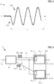
- the control device 20 can be used with the help of the alternating voltage U W , which is in Fig. 2 is shown over time t, together with the polarity switching module 35 of the transformer 30, the transistors 41, 42, 43, 44 switch to change the polarity of the transformer 30, as described below.
- the alternating voltage U W has polarity information 25A, 25B, i.e. information about how the polarity of the transformer 30 is to be switched.
- the polarity switching module 35 evaluates the polarity information 25A, 25B of the alternating voltage Uw to switch the polarity of the transformer 30.
- the polarity switching module 35 can carry out the evaluation at least partially with the help of software that runs on the polarity switching module 35.
- the polarity switching module 35 controls the transistors 41, 42, 43, 44 in order to adjust the transformer 30 from the positive polarity to the now predetermined negative polarity of the transformer 30.
- Fig. 3 shows an alternative to the voltage U W of Fig. 2 .
- the polarity switching module 35 is set in such a way that when evaluating the polarity information 25A, 25B of the alternating voltage U W it is assumed that at the beginning of a welding time T the first power pulse from the converter 22 to the transformer 30 is always sent to the connection U 1 as a negative voltage Uw the primary side of the transformer 30 is carried out. Accordingly, the polarity of the transformer 30 can be switched according to what is preset in the polarity switching module 35.
- the control device 20 of Fig. 1 can thus specify how the polarity of the transformer 30 should be switched by appropriately selecting the polarity of the alternating voltage Uw.
- the transistors 41 to 44 are then controlled by the polarity switching module 35, which evaluates the polarity of the alternating voltage U W.
- the polarity switching module 35 is designed to switch on one of the transistors 41, 42, 43, 44 depending on the alternating voltage U W and the polarity preselection.
- the series-connected transistor of the transistors 41, 42, 43, 44 is then switched on in a negative conductive manner in synchronous operation when current is present.
- the transistor pair for polarity selection is positively conductive
- the transistor pair for synchronous rectification is negatively conductive.
- the transistors 41, 43 for the polarity selection are positively conductive
- the transistors 42, 44 for the synchronous rectification are negatively conductive. If pole switching is not required, the transistors 41, 43 can be switched off Fig. 1 omitted. Alternatively, the transistors 42, 44 can be off Fig. 1 omitted.
- the transistors 41, 42 are N-channel MOSFETs. The same applies to the transistors 43, 44.
- two transistors per rectifier namely the transistors 41, 42 in the example, are connected in series in the rectifier branch or the rectifier circuit 40.
- a polarity-switchable welding voltage U21, U22 and a polarity-switchable welding current I2 can be realized on the welding transformer 30.
- the polarity information 25A, 25B is therefore linked to the power connection of the transformer 30. This means there is no cable between one Additional 24V output on inverter 22 and a corresponding input on transformer 39 are required for pole switching.
- the feedback signal for communicating the actual polarity of the transformer 30 can be dispensed with due to the evaluation by the polarity module 35. Instead, with the detection device 15, polarity monitoring is possible through the correct polarity connection of the standard detection of the electrode voltage U E during welding on the basis of a reference value detection, which is carried out during commissioning.
- the control device 20 controls the pole switching in such a way that the positive electrode of the welding tool 10 rests on the thicker component 6, for example, and the negative electrode of the welding tool 10 rests on the thinner component 7.
- the welding lens or the welding connection 8 is drawn more into the thicker component 6, since during welding the positive electrode or the electrode cap attached to it is always hotter than the negative electrode or the electrode cap attached to it and, in addition, the thinner component 7 is generally hotter than the thicker component 6. This means that the hottest point during welding is always drawn towards the positive side Electrode, here the thicker component 6, on which the positive electrode lies.
- a further advantage of the previously described control by the control device 20 is that the cap erosion on the electrodes 11, 12 is adjusted uniformly by switching the poles.
- the hotter positive electrode produces a larger cap burn than the negative electrode.
- the caps must be milled off when maximum erosion is reached and changed after repeated milling, which causes downtimes in production. Since each of the electrodes 11, 12 is switched as a positive electrode or as a negative electrode as required due to the pole switching, milling has to be done less frequently and the caps have to be changed less often. The time for production can therefore be used more effectively by controlling the control device 20 as described. In addition, valuable resources and costs are saved by requiring cap changes less frequently.
- the resistance welding device 3 has a welding transformer 300, which is constructed from a parallel connection of two transformers 30_1, 30_2.
- Each of the two transformers 30_1, 30_2 can be constructed like the transformer 30 according to Fig. 1 .
- Each of the two transformers 30_1, 30_2 is connected to the output 25 of the control device 20.
- real time is understood to mean the operation of a computing system in which programs for processing the resulting data are constantly ready for operation in such a way that the processing results are within a specified period period of time are available.
- the data can be generated randomly or at predetermined times. Accordingly are the control device 20 and the polarity switching module 35 are designed in such a way that their hardware and software do not cause or occur any delays that prevent compliance with these conditions.
- Fig. 6 shows a resistance welding device 4 according to a second exemplary embodiment.
- the resistance welding device 4 is constructed in many parts in the same manner as described for the resistance welding device 2 according to the first embodiment.
- the welding transformer 30 converts the primary voltage U1 into the first and second secondary voltages U21, U22. Here, the sum of the secondary voltages U21, U22 is smaller than the value of the primary voltage U1.
- the welding transformer 30 converts a primary current I1 on the primary side of the welding transformer 30 into the secondary current I2 on the Welding transformer secondary side 30um.
- the secondary current I2 which can also be referred to as the welding current, has a higher value than the primary current I1.
- the welding device 4 can be used instead of the welding device 2 in the system 1 according to the first exemplary embodiment.
- the rectifier 400 can be designed in the same way as described with respect to the first and second exemplary embodiments.
- the welding device 4 can also be used particularly advantageously in sheet metal combinations in which the welding electrodes burn at different levels when using a welding gun.
- the welding device 4 can be used particularly advantageously when welding chain links and when welding radiators.
- control device 20 is designed to switch on the series-connected transistor 41, 43 in a negative conductive manner in synchronous operation with electrical current.
Landscapes
- Engineering & Computer Science (AREA)
- Mechanical Engineering (AREA)
- Generation Of Surge Voltage And Current (AREA)
- Resistance Welding (AREA)
Claims (14)
- Dispositif (2 ; 3 ; 3A, 4) de soudage par résistance pour le soudage par résistance d'au moins un composant (6, 7), comprenantun outil de soudage (10) avec au moins une électrode de soudage (11, 12), qui doit être mise en contact avec ledit au moins un composant (6, 7) pour le soudage,au moins un transformateur de soudage (30) pour fournir un courant électrique à l'outil de soudage (10) lors du soudage dudit au moins un composant (6, 7),un montage en série de deux transistors (41, 42 ; 43, 44) qui sont connectés entre l'outil de soudage (10) et une sortie sur le côté secondaire du transformateur de soudage (30),caractérisé en ce que le transformateur de soudage (30) comprend un module (35) de commutation de polarité et le dispositif de soudage par résistance comprend un dispositif de commande (20) pour commander la polarité dudit au moins un transformateur de soudage (30) en envoyant au module (35) de commutation de polarité des informations de polarité (25A, 25B ; 26A, 27A ; 28A, 29A) associées à une borne de puissance (U1) du côté primaire dudit au moins un transformateur de soudage (30),les informations de polarité (25A, 25B ; 26A, 27A ; 28A, 29A) étant des informations sur la façon de commuter la polarité dudit au moins un transformateur de soudage (30),le module (35) de commutation de polarité étant conçu pour évaluer les informations de polarité (25A, 25B ; 26A, 27A ; 28A, 29A) afin de commuter la polarité dudit au moins un transformateur de soudage (30), etle module (35) de commutation de polarité étant conçu pour, en fonction de les informations de polarité (25A, 25B ; 26A, 27A ; 28A, 29A) et d'une présélection de polarité préréglée dans le module (35) de commutation de polarité, commuter un transistor (41 ; 43) du circuit en série en conduction positive en fonction du résultat d'évaluation et commuter l'autre transistor (42 ; 44) du circuit en série en conduction négative en mode synchrone en présence d'un courant électrique vers l'outil de soudage (10), grâce à quoi la polarité du premier transistor (42 ; 44) du circuit en série est tournée par rapport à la polarité de l'autre transistor (41 ; 43) du circuit en série, et de sorte que la polarité dudit au moins un transformateur de soudage (30) soit apte à être commutée pour réaliser une tension de soudage (U21, U22) à polarité commutable et un courant de soudage (12) à polarité commutable sur le transformateur de soudage (30) .
- Dispositif (2 ; 3 ; 3A, 4) de soudage par résistance selon la revendication 1, dans lequel le dispositif de commande (20) est configuré pour fournir les informations de polarité (25A, 25B) dans une tension (UW) qui est appliquée au côté primaire dudit au moins un transformateur de soudage (30).
- Dispositif (2 ; 3 ; 3A, 4) de soudage par résistance selon la revendication 1 ou la revendication 2, dans lequel le dispositif de commande (20) est configuré pour fournir les informations de polarité (26A, 27A) sous forme de signal numérique.
- Dispositif (2 ; 3 ; 3A, 4) de soudage par résistance selon l'une des revendications précédentes,dans lequel le dispositif de commande (20) et ledit au moins un transformateur de soudage (30 ; 300) sont reliés par au moins une ligne (26, 27 ; 28, 29) en plus d'une connexion pour la tension (UW) à appliquer au côté primaire dudit au moins un transformateur de soudage (30 ; 300), etdans lequel le dispositif de commande (20) est conçu pour envoyer les informations de polarité (26A, 27A ; 28A, 29A) par l'intermédiaire de ladite au moins une ligne (26, 27 ; 28, 29) au module (35) de commutation de polarité pour commuter la polarité dudit au moins un transformateur de soudage (30 ; 300).
- Dispositif (2 ; 3 ; 3A, 4) de soudage par résistance selon l'une des revendications précédentes,
dans lequel le module (35) de commutation de polarité est configuré pour évaluer les informations de polarité (25A ; 25B) dans une première impulsion de puissance provenant d'un convertisseur (22) vers ledit au moins un transformateur de soudage (30) au début d'un temps de soudage (T) pour réaliser une jonction de soudage (8) et pour commuter la polarité dudit au moins un transformateur de soudage (30) sur la base du résultat de l'évaluation. - Dispositif (2 ; 3 ; 3A, 4) de soudage par résistance selon l'une des revendications précédentes, dans lequel ledit au moins un transformateur de soudage (30) est formé par un montage en parallèle d'au moins deux transformateurs (30_1, 30_2).
- Dispositif (2 ; 3 ; 3A, 4) de soudage par résistance selon la revendication 6, dans lequel le module (35) de commutation de polarité est configuré pour toujours commuter sur la même polarité tous lesdits au moins deux transformateurs (30_1, 30_2) montés en parallèle.
- Dispositif (2 ; 3 ; 3A, 4) de soudage par résistance selon l'une des revendications précédentes,comprenant en outre un dispositif de détection (15) pour détecter une tension (UE) entre les deux électrodes de soudage (11, 12) lors du soudage avec l'outil de soudage (10),le dispositif de commande (20) étant conçu pour vérifier l'inversion de la polarité par une comparaison de la tension (UE) détectée par le dispositif de détection (15) avec une valeur de référence prédéterminée de la tension (UE).
- Dispositif (2 ; 3 ; 3A, 4) de soudage par résistance selon l'une des revendications précédentes, dans lequel le transformateur de soudage (30) comporte deux sorties (31, 33) sur chacune desquelles un montage en série de deux transistors (41, 42 ; 43, 44) est connecté en amont de l'outil de soudage (10).
- Dispositif (2 ; 3 ; 3A, 4) de soudage par résistance selon l'une des revendications précédentes, dans lequel les deux transistors (41, 42 ; 43, 44) sont des transistors à effet de champ métal-oxyde-semiconducteur.
- Dispositif (2 ; 3 ; 3A, 4) de soudage par résistance selon l'une des revendications précédentes, dans lequel l'outil de soudage (10) est une pince de soudage comportant deux électrodes de soudage (11, 12) entre lesquelles ledit au moins un composant (6, 7) est disposé pendant le soudage.
- Installation (1) pour le traitement d'objets (5), comprenantun dispositif (2 ; 3 ; 3A, 4) de soudage par résistance selon l'une des revendications précédentes,le dispositif (2 ; 3 ; 3A, 4) de soudage par résistance étant prévu pour souder par résistance au moins un composant (6, 7) prévu pour le traitement d'au moins un des objets (5).
- Installation (1) selon la revendication 12, l'installation (1) étant configurée pour la fabrication de carrosseries brutes de véhicules ou de radiateurs ou de chaînes en tant qu'objets (5).
- Procédé de soudage par résistance pour le soudage par résistance d'au moins un composant (6, 7) au moyen d'un dispositif (2 ; 3 ; 3A, 4) de soudage par résistance, le dispositif (2 ; 3 ; 3A, 4) de soudage par résistance comprenant un outil de soudage (10) avec au moins une électrode de soudage (11, 12) qui doit être mise en contact avec ledit au moins un composant (6, 7) pour le soudage, au moins un transformateur de soudage (30) pour fournir un courant électrique à l'outil de soudage (30) lors du soudage dudit au moins un composant (6, 7), un circuit en série de deux transistors (41, 42 ; 43, 44) connectés entre l'outil de soudage (10) et une sortie sur le côté secondaire du transformateur de soudage (30), un module (35) de commutation de polarité, et un dispositif de commande (20), caractérisé en ce que le procédé de soudage par résistance comprend les étapes consistant àenvoyer, avec le dispositif de commande (20), au module (35) de commutation de polarité, des informations de polarité (25A, 25B ; 26A, 27A ; 28A, 29A) associées à une borne d'alimentation (U1) sur le côté primaire dudit au moins un transformateur de soudage (30) pour commander la polarité dudit au moins un transformateur de soudage (30), les informations de polarité (25A, 25B ; 26A, 27A ; 28A, 29A) étant des informations sur la manière de commuter la polarité dudit au moins un transformateur de soudage (30), et le module (35) de commutation de polarité étant conçu pour évaluer les informations de polarité (25A, 25B ; 26A, 27A ; 28A, 29A) afin de commuter la polarité dudit au moins un transformateur de soudage (30), etcommuter, au moyen du module (35) de commutation de polarité, la polarité du transformateur de soudage (30) en utilisant les deux transistors (41, 42 ; 43, 44) en rendant l'un des transistors (41 ; 43) du circuit en série positivement conducteur en fonction des informations de polarité (25A, 25B ; 26A, 27A ; 28A, 29A) et d'une présélection de polarité préétablie dans le module (35) de commutation de polarité, etcommuter en conduction négative l'autre transistor (42 ; 44) du circuit en série en mode synchrone avec un courant électrique vers l'outil de soudage (10), ce qui fait tourner la polarité de l'un des transistors (42 ; 44) du circuit en série par rapport à la polarité de l'autre transistor (41; 43) du circuit en série, afin de réaliser une tension de soudage (U21, U22) à polarité commutable et un courant de soudage (12) à polarité commutable aux bornes du transformateur de soudage (30).
Applications Claiming Priority (1)
| Application Number | Priority Date | Filing Date | Title |
|---|---|---|---|
| DE102019205037.9A DE102019205037A1 (de) | 2019-04-09 | 2019-04-09 | Widerstandsschweissvorrichtung und widerstandsschweissverfahren zum widerstandsschweissen von mindestens einem bauteil |
Publications (3)
| Publication Number | Publication Date |
|---|---|
| EP3722041A2 EP3722041A2 (fr) | 2020-10-14 |
| EP3722041A3 EP3722041A3 (fr) | 2020-11-25 |
| EP3722041B1 true EP3722041B1 (fr) | 2023-12-27 |
Family
ID=69770567
Family Applications (1)
| Application Number | Title | Priority Date | Filing Date |
|---|---|---|---|
| EP20160830.4A Active EP3722041B1 (fr) | 2019-04-09 | 2020-03-04 | Dispositif de soudage par résistance et procédé de soudage par résistance permettant de souder par résistance au moins un composant |
Country Status (5)
| Country | Link |
|---|---|
| US (1) | US12220759B2 (fr) |
| EP (1) | EP3722041B1 (fr) |
| CN (1) | CN111790975A (fr) |
| DE (1) | DE102019205037A1 (fr) |
| ES (1) | ES2974796T3 (fr) |
Families Citing this family (3)
| Publication number | Priority date | Publication date | Assignee | Title |
|---|---|---|---|---|
| DE102021200066B4 (de) * | 2021-01-07 | 2026-01-08 | Robert Bosch Gesellschaft mit beschränkter Haftung | Schweisstransformator, schweissvorrichtung und schweissverfahren zum schweissen mindestens eines bauteils |
| DE102021204581B4 (de) * | 2021-05-06 | 2023-02-16 | Robert Bosch Gesellschaft mit beschränkter Haftung | Einrichtung und verfahren zur ansteuerung eines gleichrichters für einen schweisstransformator |
| CN113690035B (zh) * | 2021-08-20 | 2023-08-11 | 中正智控(江苏)智能科技有限公司 | 一种具有改变极性功能的次高频直流电阻焊焊接变压器 |
Citations (2)
| Publication number | Priority date | Publication date | Assignee | Title |
|---|---|---|---|---|
| WO2013063628A1 (fr) * | 2011-10-31 | 2013-05-10 | Fronius International Gmbh | Dispositif de soudage par résistance pourvu d'une source de courant située sur une pince à souder |
| EP3181284A1 (fr) * | 2015-12-17 | 2017-06-21 | Robert Bosch Gmbh | Circuit de convertisseur |
Family Cites Families (6)
| Publication number | Priority date | Publication date | Assignee | Title |
|---|---|---|---|---|
| EP0835713A1 (fr) * | 1996-09-11 | 1998-04-15 | Miyachi Technos Corporation | Méthode et appareillage pour le controle du soudage par résistance. |
| DE102011121836A1 (de) * | 2011-12-21 | 2013-06-27 | Robert Bosch Gmbh | Verfahren zum Betrieb einer Widerstandsschweißvorrichtung |
| CN108290242B (zh) * | 2015-11-09 | 2020-06-26 | 弗罗纽斯国际有限公司 | 用于在电阻焊接电流源的情况下进行数据传输的方法和用于执行该方法的电阻焊接电流源 |
| DE102015225038A1 (de) * | 2015-12-14 | 2017-06-14 | Robert Bosch Gmbh | Widerstandsschweissvorrichtung und Widerstandsschweissverfahren zum Widerstandsschweissen von mindestens einem Bauteil |
| US11027357B2 (en) * | 2017-07-28 | 2021-06-08 | Illinois Tool Works Inc. | Methods and apparatus to provide welding power |
| DE102018209983A1 (de) * | 2018-06-20 | 2019-12-24 | Robert Bosch Gmbh | Widerstandsschweissvorrichtung und Widerstandsschweissverfahren zum Widerstandsschweissen von mindestens einem Bauteil |
-
2019
- 2019-04-09 DE DE102019205037.9A patent/DE102019205037A1/de not_active Withdrawn
-
2020
- 2020-03-04 ES ES20160830T patent/ES2974796T3/es active Active
- 2020-03-04 EP EP20160830.4A patent/EP3722041B1/fr active Active
- 2020-03-31 US US16/836,145 patent/US12220759B2/en active Active
- 2020-04-08 CN CN202010269121.1A patent/CN111790975A/zh active Pending
Patent Citations (2)
| Publication number | Priority date | Publication date | Assignee | Title |
|---|---|---|---|---|
| WO2013063628A1 (fr) * | 2011-10-31 | 2013-05-10 | Fronius International Gmbh | Dispositif de soudage par résistance pourvu d'une source de courant située sur une pince à souder |
| EP3181284A1 (fr) * | 2015-12-17 | 2017-06-21 | Robert Bosch Gmbh | Circuit de convertisseur |
Also Published As
| Publication number | Publication date |
|---|---|
| EP3722041A3 (fr) | 2020-11-25 |
| EP3722041A2 (fr) | 2020-10-14 |
| DE102019205037A1 (de) | 2020-10-15 |
| CN111790975A (zh) | 2020-10-20 |
| US20200324359A1 (en) | 2020-10-15 |
| ES2974796T3 (es) | 2024-07-01 |
| US12220759B2 (en) | 2025-02-11 |
Similar Documents
| Publication | Publication Date | Title |
|---|---|---|
| EP3722041A2 (fr) | Dispositif de soudage par résistance et procédé de soudage par résistance permettant de souder par résistance au moins un composant | |
| DE202012013015U1 (de) | Echtzeit-Induktivitätsüberwachung in einer Schweiß- und Schneidstromversorgung | |
| DE202012012992U1 (de) | Vorrichtung zum Impulsschweißen mit Wechselstromwellenform | |
| DE212014000073U1 (de) | Vorrichtung zum Schweissen mit einer Wechselstromwellenform | |
| DE212013000077U1 (de) | Arbeitsstromumschaltung zum Beseitigen der Lichtbogenablenkung | |
| EP2020830A2 (fr) | Procédé de commande d'un variateur universel | |
| EP2959492B1 (fr) | Procédé pour faire fonctionner un changeur de prises en charge avec des éléments de commutation à semi-conducteurs | |
| EP3584029A1 (fr) | Dispositif de soudage par résistance et procédé de soudage par résistance permettant de souder par résistance au moins un composant | |
| DE69402939T2 (de) | Anlage zur Oberflächenbehandlung von metallischer Werkstücken durch Kataphorese, insbesondere von Automobilkarosserien | |
| DE102014216551B4 (de) | Verfahren und Vorrichtung zur Totzeitregelung in Schaltnetzteilen | |
| DE2246846A1 (de) | Widerstandsschweissmaschine | |
| EP0379608B1 (fr) | Méthode et appareil pour la commande d'organes de réglage de courant alternatif monophasés ou polyphasés | |
| DE102021204581B4 (de) | Einrichtung und verfahren zur ansteuerung eines gleichrichters für einen schweisstransformator | |
| DE19751828A1 (de) | Verfahren und Vorrichtung zur Erkennung und Steuerung von elektronischen Schaltnetzteilen oder konventionellen Transformatoren, jeweils mit oder ohne ohmscher Last, insbesondere von Beleuchtungseinrichtungen | |
| DE102015225038A1 (de) | Widerstandsschweissvorrichtung und Widerstandsschweissverfahren zum Widerstandsschweissen von mindestens einem Bauteil | |
| EP4032651B1 (fr) | Dispositif de soudage par résistance et procédé de soudage par résistance | |
| EP2193005B1 (fr) | Procédé de fonctionnement d'un dispositif de soudage par résistance | |
| DE10114323A1 (de) | Vorrichtung zum Widerstandsschweißen | |
| EP3718672B1 (fr) | Redresseur pour un transformateur de soudage d'un dispositif de soudage et procédé de fabrication d'un tel redresseur | |
| EP2974820B1 (fr) | Appareil de soudure à arcs électriques, système et procédé de démagnétisation d'un tube métallique | |
| EP3718673B1 (fr) | Redresseur pour un transformateur de soudage d'un dispositif de soudage et procédé de fabrication d'un tel redresseur | |
| DE29508868U1 (de) | Vorrichtung zum Elektroschweißen | |
| DE3330702C2 (fr) | ||
| DD203840A1 (de) | Verfahren und steueranordnung zum widerstandsschweissen | |
| DE29508869U1 (de) | Vorrichtung zum Elektroschweißen |
Legal Events
| Date | Code | Title | Description |
|---|---|---|---|
| PUAI | Public reference made under article 153(3) epc to a published international application that has entered the european phase |
Free format text: ORIGINAL CODE: 0009012 |
|
| STAA | Information on the status of an ep patent application or granted ep patent |
Free format text: STATUS: THE APPLICATION HAS BEEN PUBLISHED |
|
| AK | Designated contracting states |
Kind code of ref document: A2 Designated state(s): AL AT BE BG CH CY CZ DE DK EE ES FI FR GB GR HR HU IE IS IT LI LT LU LV MC MK MT NL NO PL PT RO RS SE SI SK SM TR |
|
| AX | Request for extension of the european patent |
Extension state: BA ME |
|
| PUAL | Search report despatched |
Free format text: ORIGINAL CODE: 0009013 |
|
| AK | Designated contracting states |
Kind code of ref document: A3 Designated state(s): AL AT BE BG CH CY CZ DE DK EE ES FI FR GB GR HR HU IE IS IT LI LT LU LV MC MK MT NL NO PL PT RO RS SE SI SK SM TR |
|
| AX | Request for extension of the european patent |
Extension state: BA ME |
|
| RIC1 | Information provided on ipc code assigned before grant |
Ipc: B23K 11/24 20060101AFI20201022BHEP |
|
| STAA | Information on the status of an ep patent application or granted ep patent |
Free format text: STATUS: REQUEST FOR EXAMINATION WAS MADE |
|
| 17P | Request for examination filed |
Effective date: 20210525 |
|
| RBV | Designated contracting states (corrected) |
Designated state(s): AL AT BE BG CH CY CZ DE DK EE ES FI FR GB GR HR HU IE IS IT LI LT LU LV MC MK MT NL NO PL PT RO RS SE SI SK SM TR |
|
| STAA | Information on the status of an ep patent application or granted ep patent |
Free format text: STATUS: EXAMINATION IS IN PROGRESS |
|
| 17Q | First examination report despatched |
Effective date: 20211213 |
|
| GRAP | Despatch of communication of intention to grant a patent |
Free format text: ORIGINAL CODE: EPIDOSNIGR1 |
|
| STAA | Information on the status of an ep patent application or granted ep patent |
Free format text: STATUS: GRANT OF PATENT IS INTENDED |
|
| INTG | Intention to grant announced |
Effective date: 20231011 |
|
| GRAS | Grant fee paid |
Free format text: ORIGINAL CODE: EPIDOSNIGR3 |
|
| GRAA | (expected) grant |
Free format text: ORIGINAL CODE: 0009210 |
|
| STAA | Information on the status of an ep patent application or granted ep patent |
Free format text: STATUS: THE PATENT HAS BEEN GRANTED |
|
| AK | Designated contracting states |
Kind code of ref document: B1 Designated state(s): AL AT BE BG CH CY CZ DE DK EE ES FI FR GB GR HR HU IE IS IT LI LT LU LV MC MK MT NL NO PL PT RO RS SE SI SK SM TR |
|
| REG | Reference to a national code |
Ref country code: GB Ref legal event code: FG4D Free format text: NOT ENGLISH |
|
| REG | Reference to a national code |
Ref country code: CH Ref legal event code: EP |
|
| REG | Reference to a national code |
Ref country code: DE Ref legal event code: R096 Ref document number: 502020006483 Country of ref document: DE |
|
| REG | Reference to a national code |
Ref country code: IE Ref legal event code: FG4D Free format text: LANGUAGE OF EP DOCUMENT: GERMAN |
|
| PG25 | Lapsed in a contracting state [announced via postgrant information from national office to epo] |
Ref country code: GR Free format text: LAPSE BECAUSE OF FAILURE TO SUBMIT A TRANSLATION OF THE DESCRIPTION OR TO PAY THE FEE WITHIN THE PRESCRIBED TIME-LIMIT Effective date: 20240328 |
|
| REG | Reference to a national code |
Ref country code: LT Ref legal event code: MG9D |
|
| PG25 | Lapsed in a contracting state [announced via postgrant information from national office to epo] |
Ref country code: LT Free format text: LAPSE BECAUSE OF FAILURE TO SUBMIT A TRANSLATION OF THE DESCRIPTION OR TO PAY THE FEE WITHIN THE PRESCRIBED TIME-LIMIT Effective date: 20231227 |
|
| PG25 | Lapsed in a contracting state [announced via postgrant information from national office to epo] |
Ref country code: LT Free format text: LAPSE BECAUSE OF FAILURE TO SUBMIT A TRANSLATION OF THE DESCRIPTION OR TO PAY THE FEE WITHIN THE PRESCRIBED TIME-LIMIT Effective date: 20231227 Ref country code: GR Free format text: LAPSE BECAUSE OF FAILURE TO SUBMIT A TRANSLATION OF THE DESCRIPTION OR TO PAY THE FEE WITHIN THE PRESCRIBED TIME-LIMIT Effective date: 20240328 Ref country code: FI Free format text: LAPSE BECAUSE OF FAILURE TO SUBMIT A TRANSLATION OF THE DESCRIPTION OR TO PAY THE FEE WITHIN THE PRESCRIBED TIME-LIMIT Effective date: 20231227 Ref country code: BG Free format text: LAPSE BECAUSE OF FAILURE TO SUBMIT A TRANSLATION OF THE DESCRIPTION OR TO PAY THE FEE WITHIN THE PRESCRIBED TIME-LIMIT Effective date: 20240327 |
|
| REG | Reference to a national code |
Ref country code: NL Ref legal event code: MP Effective date: 20231227 |
|
| PG25 | Lapsed in a contracting state [announced via postgrant information from national office to epo] |
Ref country code: NL Free format text: LAPSE BECAUSE OF FAILURE TO SUBMIT A TRANSLATION OF THE DESCRIPTION OR TO PAY THE FEE WITHIN THE PRESCRIBED TIME-LIMIT Effective date: 20231227 |
|
| PG25 | Lapsed in a contracting state [announced via postgrant information from national office to epo] |
Ref country code: SE Free format text: LAPSE BECAUSE OF FAILURE TO SUBMIT A TRANSLATION OF THE DESCRIPTION OR TO PAY THE FEE WITHIN THE PRESCRIBED TIME-LIMIT Effective date: 20231227 Ref country code: RS Free format text: LAPSE BECAUSE OF FAILURE TO SUBMIT A TRANSLATION OF THE DESCRIPTION OR TO PAY THE FEE WITHIN THE PRESCRIBED TIME-LIMIT Effective date: 20231227 Ref country code: NO Free format text: LAPSE BECAUSE OF FAILURE TO SUBMIT A TRANSLATION OF THE DESCRIPTION OR TO PAY THE FEE WITHIN THE PRESCRIBED TIME-LIMIT Effective date: 20240327 Ref country code: NL Free format text: LAPSE BECAUSE OF FAILURE TO SUBMIT A TRANSLATION OF THE DESCRIPTION OR TO PAY THE FEE WITHIN THE PRESCRIBED TIME-LIMIT Effective date: 20231227 Ref country code: LV Free format text: LAPSE BECAUSE OF FAILURE TO SUBMIT A TRANSLATION OF THE DESCRIPTION OR TO PAY THE FEE WITHIN THE PRESCRIBED TIME-LIMIT Effective date: 20231227 Ref country code: HR Free format text: LAPSE BECAUSE OF FAILURE TO SUBMIT A TRANSLATION OF THE DESCRIPTION OR TO PAY THE FEE WITHIN THE PRESCRIBED TIME-LIMIT Effective date: 20231227 |
|
| PG25 | Lapsed in a contracting state [announced via postgrant information from national office to epo] |
Ref country code: IS Free format text: LAPSE BECAUSE OF FAILURE TO SUBMIT A TRANSLATION OF THE DESCRIPTION OR TO PAY THE FEE WITHIN THE PRESCRIBED TIME-LIMIT Effective date: 20240427 |
|
| REG | Reference to a national code |
Ref country code: ES Ref legal event code: FG2A Ref document number: 2974796 Country of ref document: ES Kind code of ref document: T3 Effective date: 20240701 |
|
| PG25 | Lapsed in a contracting state [announced via postgrant information from national office to epo] |
Ref country code: CZ Free format text: LAPSE BECAUSE OF FAILURE TO SUBMIT A TRANSLATION OF THE DESCRIPTION OR TO PAY THE FEE WITHIN THE PRESCRIBED TIME-LIMIT Effective date: 20231227 |
|
| PG25 | Lapsed in a contracting state [announced via postgrant information from national office to epo] |
Ref country code: SK Free format text: LAPSE BECAUSE OF FAILURE TO SUBMIT A TRANSLATION OF THE DESCRIPTION OR TO PAY THE FEE WITHIN THE PRESCRIBED TIME-LIMIT Effective date: 20231227 |
|
| PG25 | Lapsed in a contracting state [announced via postgrant information from national office to epo] |
Ref country code: SM Free format text: LAPSE BECAUSE OF FAILURE TO SUBMIT A TRANSLATION OF THE DESCRIPTION OR TO PAY THE FEE WITHIN THE PRESCRIBED TIME-LIMIT Effective date: 20231227 Ref country code: SK Free format text: LAPSE BECAUSE OF FAILURE TO SUBMIT A TRANSLATION OF THE DESCRIPTION OR TO PAY THE FEE WITHIN THE PRESCRIBED TIME-LIMIT Effective date: 20231227 Ref country code: RO Free format text: LAPSE BECAUSE OF FAILURE TO SUBMIT A TRANSLATION OF THE DESCRIPTION OR TO PAY THE FEE WITHIN THE PRESCRIBED TIME-LIMIT Effective date: 20231227 Ref country code: IT Free format text: LAPSE BECAUSE OF FAILURE TO SUBMIT A TRANSLATION OF THE DESCRIPTION OR TO PAY THE FEE WITHIN THE PRESCRIBED TIME-LIMIT Effective date: 20231227 Ref country code: IS Free format text: LAPSE BECAUSE OF FAILURE TO SUBMIT A TRANSLATION OF THE DESCRIPTION OR TO PAY THE FEE WITHIN THE PRESCRIBED TIME-LIMIT Effective date: 20240427 Ref country code: EE Free format text: LAPSE BECAUSE OF FAILURE TO SUBMIT A TRANSLATION OF THE DESCRIPTION OR TO PAY THE FEE WITHIN THE PRESCRIBED TIME-LIMIT Effective date: 20231227 Ref country code: CZ Free format text: LAPSE BECAUSE OF FAILURE TO SUBMIT A TRANSLATION OF THE DESCRIPTION OR TO PAY THE FEE WITHIN THE PRESCRIBED TIME-LIMIT Effective date: 20231227 |
|
| PG25 | Lapsed in a contracting state [announced via postgrant information from national office to epo] |
Ref country code: PL Free format text: LAPSE BECAUSE OF FAILURE TO SUBMIT A TRANSLATION OF THE DESCRIPTION OR TO PAY THE FEE WITHIN THE PRESCRIBED TIME-LIMIT Effective date: 20231227 Ref country code: PT Free format text: LAPSE BECAUSE OF FAILURE TO SUBMIT A TRANSLATION OF THE DESCRIPTION OR TO PAY THE FEE WITHIN THE PRESCRIBED TIME-LIMIT Effective date: 20240429 |
|
| PG25 | Lapsed in a contracting state [announced via postgrant information from national office to epo] |
Ref country code: PT Free format text: LAPSE BECAUSE OF FAILURE TO SUBMIT A TRANSLATION OF THE DESCRIPTION OR TO PAY THE FEE WITHIN THE PRESCRIBED TIME-LIMIT Effective date: 20240429 Ref country code: PL Free format text: LAPSE BECAUSE OF FAILURE TO SUBMIT A TRANSLATION OF THE DESCRIPTION OR TO PAY THE FEE WITHIN THE PRESCRIBED TIME-LIMIT Effective date: 20231227 |
|
| REG | Reference to a national code |
Ref country code: DE Ref legal event code: R097 Ref document number: 502020006483 Country of ref document: DE |
|
| PG25 | Lapsed in a contracting state [announced via postgrant information from national office to epo] |
Ref country code: DK Free format text: LAPSE BECAUSE OF FAILURE TO SUBMIT A TRANSLATION OF THE DESCRIPTION OR TO PAY THE FEE WITHIN THE PRESCRIBED TIME-LIMIT Effective date: 20231227 |
|
| PG25 | Lapsed in a contracting state [announced via postgrant information from national office to epo] |
Ref country code: DK Free format text: LAPSE BECAUSE OF FAILURE TO SUBMIT A TRANSLATION OF THE DESCRIPTION OR TO PAY THE FEE WITHIN THE PRESCRIBED TIME-LIMIT Effective date: 20231227 |
|
| REG | Reference to a national code |
Ref country code: CH Ref legal event code: PL |
|
| PLBE | No opposition filed within time limit |
Free format text: ORIGINAL CODE: 0009261 |
|
| STAA | Information on the status of an ep patent application or granted ep patent |
Free format text: STATUS: NO OPPOSITION FILED WITHIN TIME LIMIT |
|
| PG25 | Lapsed in a contracting state [announced via postgrant information from national office to epo] |
Ref country code: LU Free format text: LAPSE BECAUSE OF NON-PAYMENT OF DUE FEES Effective date: 20240304 |
|
| PG25 | Lapsed in a contracting state [announced via postgrant information from national office to epo] |
Ref country code: MC Free format text: LAPSE BECAUSE OF FAILURE TO SUBMIT A TRANSLATION OF THE DESCRIPTION OR TO PAY THE FEE WITHIN THE PRESCRIBED TIME-LIMIT Effective date: 20231227 |
|
| GBPC | Gb: european patent ceased through non-payment of renewal fee |
Effective date: 20240327 |
|
| PG25 | Lapsed in a contracting state [announced via postgrant information from national office to epo] |
Ref country code: MC Free format text: LAPSE BECAUSE OF FAILURE TO SUBMIT A TRANSLATION OF THE DESCRIPTION OR TO PAY THE FEE WITHIN THE PRESCRIBED TIME-LIMIT Effective date: 20231227 Ref country code: LU Free format text: LAPSE BECAUSE OF NON-PAYMENT OF DUE FEES Effective date: 20240304 |
|
| 26N | No opposition filed |
Effective date: 20240930 |
|
| REG | Reference to a national code |
Ref country code: BE Ref legal event code: MM Effective date: 20240331 |
|
| PG25 | Lapsed in a contracting state [announced via postgrant information from national office to epo] |
Ref country code: BE Free format text: LAPSE BECAUSE OF NON-PAYMENT OF DUE FEES Effective date: 20240331 |
|
| PG25 | Lapsed in a contracting state [announced via postgrant information from national office to epo] |
Ref country code: GB Free format text: LAPSE BECAUSE OF NON-PAYMENT OF DUE FEES Effective date: 20240327 |
|
| PG25 | Lapsed in a contracting state [announced via postgrant information from national office to epo] |
Ref country code: IE Free format text: LAPSE BECAUSE OF NON-PAYMENT OF DUE FEES Effective date: 20240304 |
|
| PG25 | Lapsed in a contracting state [announced via postgrant information from national office to epo] |
Ref country code: IE Free format text: LAPSE BECAUSE OF NON-PAYMENT OF DUE FEES Effective date: 20240304 Ref country code: GB Free format text: LAPSE BECAUSE OF NON-PAYMENT OF DUE FEES Effective date: 20240327 Ref country code: BE Free format text: LAPSE BECAUSE OF NON-PAYMENT OF DUE FEES Effective date: 20240331 Ref country code: CH Free format text: LAPSE BECAUSE OF NON-PAYMENT OF DUE FEES Effective date: 20240331 |
|
| PG25 | Lapsed in a contracting state [announced via postgrant information from national office to epo] |
Ref country code: SI Free format text: LAPSE BECAUSE OF FAILURE TO SUBMIT A TRANSLATION OF THE DESCRIPTION OR TO PAY THE FEE WITHIN THE PRESCRIBED TIME-LIMIT Effective date: 20231227 |
|
| PGFP | Annual fee paid to national office [announced via postgrant information from national office to epo] |
Ref country code: AT Payment date: 20250417 Year of fee payment: 5 |
|
| PGFP | Annual fee paid to national office [announced via postgrant information from national office to epo] |
Ref country code: DE Payment date: 20250522 Year of fee payment: 6 |
|
| PGFP | Annual fee paid to national office [announced via postgrant information from national office to epo] |
Ref country code: ES Payment date: 20250416 Year of fee payment: 6 |
|
| PG25 | Lapsed in a contracting state [announced via postgrant information from national office to epo] |
Ref country code: CY Free format text: LAPSE BECAUSE OF FAILURE TO SUBMIT A TRANSLATION OF THE DESCRIPTION OR TO PAY THE FEE WITHIN THE PRESCRIBED TIME-LIMIT; INVALID AB INITIO Effective date: 20200304 |
|
| PG25 | Lapsed in a contracting state [announced via postgrant information from national office to epo] |
Ref country code: HU Free format text: LAPSE BECAUSE OF FAILURE TO SUBMIT A TRANSLATION OF THE DESCRIPTION OR TO PAY THE FEE WITHIN THE PRESCRIBED TIME-LIMIT; INVALID AB INITIO Effective date: 20200304 |
|
| PG25 | Lapsed in a contracting state [announced via postgrant information from national office to epo] |
Ref country code: TR Free format text: LAPSE BECAUSE OF FAILURE TO SUBMIT A TRANSLATION OF THE DESCRIPTION OR TO PAY THE FEE WITHIN THE PRESCRIBED TIME-LIMIT Effective date: 20231227 |
|
| PGFP | Annual fee paid to national office [announced via postgrant information from national office to epo] |
Ref country code: FR Payment date: 20260325 Year of fee payment: 7 |