EP3722065A9 - Pièce de garniture de véhicule automobile et son procédé de fabrication - Google Patents
Pièce de garniture de véhicule automobile et son procédé de fabrication Download PDFInfo
- Publication number
- EP3722065A9 EP3722065A9 EP19168421.6A EP19168421A EP3722065A9 EP 3722065 A9 EP3722065 A9 EP 3722065A9 EP 19168421 A EP19168421 A EP 19168421A EP 3722065 A9 EP3722065 A9 EP 3722065A9
- Authority
- EP
- European Patent Office
- Prior art keywords
- plastic material
- functional
- decorative
- functional part
- carrier
- Prior art date
- Legal status (The legal status is an assumption and is not a legal conclusion. Google has not performed a legal analysis and makes no representation as to the accuracy of the status listed.)
- Withdrawn
Links
- 238000004519 manufacturing process Methods 0.000 title claims description 8
- 239000000463 material Substances 0.000 claims abstract description 120
- 229920003023 plastic Polymers 0.000 claims abstract description 108
- 239000004033 plastic Substances 0.000 claims abstract description 108
- 238000001746 injection moulding Methods 0.000 claims abstract description 17
- 230000035515 penetration Effects 0.000 claims description 24
- 238000002347 injection Methods 0.000 claims description 13
- 239000007924 injection Substances 0.000 claims description 13
- 238000000034 method Methods 0.000 claims description 11
- 230000007704 transition Effects 0.000 claims description 7
- 238000003780 insertion Methods 0.000 claims 1
- 230000037431 insertion Effects 0.000 claims 1
- 238000000576 coating method Methods 0.000 description 6
- 239000011248 coating agent Substances 0.000 description 5
- 238000005520 cutting process Methods 0.000 description 5
- 229920002396 Polyurea Polymers 0.000 description 3
- XECAHXYUAAWDEL-UHFFFAOYSA-N acrylonitrile butadiene styrene Chemical compound C=CC=C.C=CC#N.C=CC1=CC=CC=C1 XECAHXYUAAWDEL-UHFFFAOYSA-N 0.000 description 3
- 229920000122 acrylonitrile butadiene styrene Polymers 0.000 description 3
- 239000004676 acrylonitrile butadiene styrene Substances 0.000 description 3
- 239000000853 adhesive Substances 0.000 description 3
- 230000001070 adhesive effect Effects 0.000 description 3
- 239000004922 lacquer Substances 0.000 description 3
- 238000007591 painting process Methods 0.000 description 3
- 239000004417 polycarbonate Substances 0.000 description 3
- 229920000515 polycarbonate Polymers 0.000 description 3
- 239000004814 polyurethane Substances 0.000 description 3
- 230000003678 scratch resistant effect Effects 0.000 description 3
- 229920002877 acrylic styrene acrylonitrile Polymers 0.000 description 2
- 230000035699 permeability Effects 0.000 description 2
- 229920003229 poly(methyl methacrylate) Polymers 0.000 description 2
- 229920002285 poly(styrene-co-acrylonitrile) Polymers 0.000 description 2
- 239000004926 polymethyl methacrylate Substances 0.000 description 2
- 229920003226 polyurethane urea Polymers 0.000 description 2
- 238000010107 reaction injection moulding Methods 0.000 description 2
- 125000006850 spacer group Chemical group 0.000 description 2
- YAAQEISEHDUIFO-UHFFFAOYSA-N C=CC#N.OC(=O)C=CC=CC1=CC=CC=C1 Chemical compound C=CC#N.OC(=O)C=CC=CC1=CC=CC=C1 YAAQEISEHDUIFO-UHFFFAOYSA-N 0.000 description 1
- 238000004378 air conditioning Methods 0.000 description 1
- 238000010276 construction Methods 0.000 description 1
- 230000002349 favourable effect Effects 0.000 description 1
- 239000006261 foam material Substances 0.000 description 1
- 239000011888 foil Substances 0.000 description 1
- 238000003384 imaging method Methods 0.000 description 1
- 238000007654 immersion Methods 0.000 description 1
- 239000003973 paint Substances 0.000 description 1
- 229920002635 polyurethane Polymers 0.000 description 1
- 238000003825 pressing Methods 0.000 description 1
- 238000007789 sealing Methods 0.000 description 1
- 239000000779 smoke Substances 0.000 description 1
- 239000007921 spray Substances 0.000 description 1
- 229920001169 thermoplastic Polymers 0.000 description 1
- 239000004416 thermosoftening plastic Substances 0.000 description 1
Images

Classifications
-
- B—PERFORMING OPERATIONS; TRANSPORTING
- B29—WORKING OF PLASTICS; WORKING OF SUBSTANCES IN A PLASTIC STATE IN GENERAL
- B29C—SHAPING OR JOINING OF PLASTICS; SHAPING OF MATERIAL IN A PLASTIC STATE, NOT OTHERWISE PROVIDED FOR; AFTER-TREATMENT OF THE SHAPED PRODUCTS, e.g. REPAIRING
- B29C45/00—Injection moulding, i.e. forcing the required volume of moulding material through a nozzle into a closed mould; Apparatus therefor
- B29C45/14—Injection moulding, i.e. forcing the required volume of moulding material through a nozzle into a closed mould; Apparatus therefor incorporating preformed parts or layers, e.g. injection moulding around inserts or for coating articles
- B29C45/14311—Injection moulding, i.e. forcing the required volume of moulding material through a nozzle into a closed mould; Apparatus therefor incorporating preformed parts or layers, e.g. injection moulding around inserts or for coating articles using means for bonding the coating to the articles
-
- B—PERFORMING OPERATIONS; TRANSPORTING
- B29—WORKING OF PLASTICS; WORKING OF SUBSTANCES IN A PLASTIC STATE IN GENERAL
- B29C—SHAPING OR JOINING OF PLASTICS; SHAPING OF MATERIAL IN A PLASTIC STATE, NOT OTHERWISE PROVIDED FOR; AFTER-TREATMENT OF THE SHAPED PRODUCTS, e.g. REPAIRING
- B29C45/00—Injection moulding, i.e. forcing the required volume of moulding material through a nozzle into a closed mould; Apparatus therefor
- B29C45/16—Making multilayered or multicoloured articles
- B29C45/1642—Making multilayered or multicoloured articles having a "sandwich" structure
- B29C45/1643—Making multilayered or multicoloured articles having a "sandwich" structure from at least three different materials or with at least four layers
-
- B—PERFORMING OPERATIONS; TRANSPORTING
- B29—WORKING OF PLASTICS; WORKING OF SUBSTANCES IN A PLASTIC STATE IN GENERAL
- B29C—SHAPING OR JOINING OF PLASTICS; SHAPING OF MATERIAL IN A PLASTIC STATE, NOT OTHERWISE PROVIDED FOR; AFTER-TREATMENT OF THE SHAPED PRODUCTS, e.g. REPAIRING
- B29C45/00—Injection moulding, i.e. forcing the required volume of moulding material through a nozzle into a closed mould; Apparatus therefor
- B29C45/16—Making multilayered or multicoloured articles
- B29C45/1657—Making multilayered or multicoloured articles using means for adhering or bonding the layers or parts to each other
-
- B—PERFORMING OPERATIONS; TRANSPORTING
- B29—WORKING OF PLASTICS; WORKING OF SUBSTANCES IN A PLASTIC STATE IN GENERAL
- B29C—SHAPING OR JOINING OF PLASTICS; SHAPING OF MATERIAL IN A PLASTIC STATE, NOT OTHERWISE PROVIDED FOR; AFTER-TREATMENT OF THE SHAPED PRODUCTS, e.g. REPAIRING
- B29C45/00—Injection moulding, i.e. forcing the required volume of moulding material through a nozzle into a closed mould; Apparatus therefor
- B29C45/14—Injection moulding, i.e. forcing the required volume of moulding material through a nozzle into a closed mould; Apparatus therefor incorporating preformed parts or layers, e.g. injection moulding around inserts or for coating articles
- B29C45/14311—Injection moulding, i.e. forcing the required volume of moulding material through a nozzle into a closed mould; Apparatus therefor incorporating preformed parts or layers, e.g. injection moulding around inserts or for coating articles using means for bonding the coating to the articles
- B29C2045/14327—Injection moulding, i.e. forcing the required volume of moulding material through a nozzle into a closed mould; Apparatus therefor incorporating preformed parts or layers, e.g. injection moulding around inserts or for coating articles using means for bonding the coating to the articles anchoring by forcing the material to pass through a hole in the article
-
- B—PERFORMING OPERATIONS; TRANSPORTING
- B29—WORKING OF PLASTICS; WORKING OF SUBSTANCES IN A PLASTIC STATE IN GENERAL
- B29C—SHAPING OR JOINING OF PLASTICS; SHAPING OF MATERIAL IN A PLASTIC STATE, NOT OTHERWISE PROVIDED FOR; AFTER-TREATMENT OF THE SHAPED PRODUCTS, e.g. REPAIRING
- B29C45/00—Injection moulding, i.e. forcing the required volume of moulding material through a nozzle into a closed mould; Apparatus therefor
- B29C45/16—Making multilayered or multicoloured articles
- B29C2045/167—Making multilayered or multicoloured articles injecting the second layer through the first layer
-
- B—PERFORMING OPERATIONS; TRANSPORTING
- B29—WORKING OF PLASTICS; WORKING OF SUBSTANCES IN A PLASTIC STATE IN GENERAL
- B29K—INDEXING SCHEME ASSOCIATED WITH SUBCLASSES B29B, B29C OR B29D, RELATING TO MOULDING MATERIALS OR TO MATERIALS FOR MOULDS, REINFORCEMENTS, FILLERS OR PREFORMED PARTS, e.g. INSERTS
- B29K2995/00—Properties of moulding materials, reinforcements, fillers, preformed parts or moulds
- B29K2995/0018—Properties of moulding materials, reinforcements, fillers, preformed parts or moulds having particular optical properties, e.g. fluorescent or phosphorescent
- B29K2995/0026—Transparent
Definitions
- the invention relates to a motor vehicle trim part produced in a multi-component injection molding process with a decorative surface facing the vehicle user when used as intended, and a method for its production.
- the motor vehicle trim part is set up and designed in such a way that an electronic functional element is arranged on the back in the area of a functional section formed by a functional part, by means of which control surfaces and / or display surfaces that can be actuated on the front side via the decorative surface and are created optically in the decorative surface are created.
- Decorative parts for motor vehicles that are manufactured in a multi-component injection molding process and have a carrier part made of a first plastic material on the back and a cover layer made of a second plastic material on the front to create a decorative surface, and have electronic functional elements embedded in the back or in the injection molded material, are known to those skilled in the art known.
- WO 2010/115585 A1 describes a motor vehicle cover produced in a multi-component injection molding process, in which a carrier part is produced from a first plastic material and this is then overmolded with a cover layer over the entire surface with a second plastic material to produce a decorative surface.
- the second plastic material is transparent or semi-transparent and on the front covers a recess formed in the carrier part during injection molding, into which an electronic functional element or functional components assigned to it are inserted on the rear.
- a particular disadvantage of this configuration is that the materials which are suitable as a second plastic material in such a construction, only have a limited scratch resistance, which can permanently reduce the impression of quality and impair the functional reliability of the electronic functional elements arranged on the rear.
- a thickness of the top layer of about 2.5 mm is also required to ensure sufficient structural rigidity of the overall component and the cover layer itself and due to the high processing viscosity of the plastic materials used, which makes the motor vehicle panel relatively thick overall and a comparatively high one Brings material costs with it.
- the object of the invention is to provide a motor vehicle trim part which is improved compared to the prior art and an improved method for producing a motor vehicle trim part.
- the motor vehicle trim part should have a decorative surface facing the vehicle user, in which display and / or control surfaces are implemented, with increased strength and still enable a narrower structure than conventional motor vehicle trim parts.
- the object is achieved by a motor vehicle trim part according to claim 1 and the method defined in claims 12 and 14 for producing a motor vehicle trim part.
- the motor vehicle trim part has a decorative surface formed by a cover layer and comprises a carrier part produced from a first plastic material in the injection molding process with a front side and a rear side, a functional part produced from a second plastic material with a front side and a rear side.
- the functional part is at least partially encapsulated by the first plastic material or the second plastic material is at least partially injected into a recess left in the first plastic material, and the front sides of the carrier part and functional part are provided with a third plastic material forming the cover layer to form a continuous decorative surface.
- the third plastic material forming the cover layer is preferably applied to the third plastic material in an IMC (In-Mold-Coating) process by flooding the front sides of the carrier part and functional part with the third plastic material.
- cover layer is applied outside the injection molding tool in a separate process step following the injection molding process of the carrier part and the functional part, e.g. through a subsequent coating or painting process, for example through a spray or immersion process. This means that materials can also be used that are unsuitable for processing in an IMC process.
- a first plastic material to be injected into an injection mold to create a carrier part with a front and a back, forming a recess that remains in the carrier, and a second plastic material to create a functional part with a front and a rear is at least partially injected into the recess.
- a functional part made of a second plastic material and having a front side and a rear side is first placed or injected into an injection mold and then, to create a carrier part with a front side and a rear side, a first plastic material is injected while at least partially encapsulating the functional part becomes.
- the front sides of the carrier part and the functional part are then provided with a third plastic material to create the continuous cover layer that covers the front sides of the carrier part and the functional part, depending on the method used, before or after demolding from the injection molding tool.
- the invention is based, among other things, on the consideration that the structural rigidity of the component, while at the same time creating the possibility of realizing operating or display areas on the outside, no longer has to be significantly supported by the plastic material forming the decorative surface, if it is ensured that the under it The structure lying on the third plastic material already has sufficient structural rigidity and functionality in itself.
- the structure underlying the material layer (cover layer) forming the decorative surface can have the advantageous hybrid structure known from multi-component trim parts, which is made possible by the use of two different plastic materials, because it is already produced in a multi-component manner using different plastic materials.
- the carrier part can still be formed from an impact-resistant and ductile first plastic material which is advantageous for fastening the decorative part to the vehicle and does not have to be (semi) transparent or translucent or transmissive in the required manner. Only in a limited sub-area of a functional section in which the front display and / or control surfaces are to be implemented is a second plastic material used to form a functional part, which is then (semi-) transparent or translucent or transmissive in the required manner can be.
- the third plastic material forming the cover layer and thus the decorative surface can be flooded or otherwise applied over the front sides of the carrier part and functional part, which together form a front side of the intermediate component not yet provided with the cover layer, which is to be continuously covered with the third plastic material.
- the first plastic material, the second plastic material and the third plastic material are preferably plastic materials which differ from one another.
- the first plastic material used is preferably an impact-resistant, ductile plastic, in particular an acrylonitrile-butadiene-styrene copolymer (ABS), an acrylonitrile-styrene-acrylate copolymer (ASA) or a polyblend with polycarbonate as a component, for example a PC ABS polyblend.
- ABS acrylonitrile-butadiene-styrene copolymer
- ASA acrylonitrile-styrene-acrylate copolymer
- the first plastic material can be a light-impermeable, opaque plastic.
- a plastic that is transmissive for electromagnetic waves, in particular for light can be used as the second plastic material. If light permeability is desired, this can be clear-transparent (view- or image-permeable) or semitransparent or else translucent (light-permeable, but not view- or image-permeable).
- Suitable plastic materials are in particular styrene-acrylonitrile copolymers (SAN), polymethyl methacrylate (PMMA) or polycarbonate (PC).
- the third plastic material which forms the outer cover layer, is preferably a reactive plastic lacquer, for example a polyurethane or polyurea-based lacquer, or some other suitable, preferably highly scratch-resistant, hard lacquer. If light permeability is desired, the third plastic material can also be clear-transparent (view- or image-permeable) or semitransparent or else translucent (light-permeable, but not view- or image-permeable).
- a reactive plastic lacquer for example a polyurethane or polyurea-based lacquer, or some other suitable, preferably highly scratch-resistant, hard lacquer. If light permeability is desired, the third plastic material can also be clear-transparent (view- or image-permeable) or semitransparent or else translucent (light-permeable, but not view- or image-permeable).
- the second plastic material and the third plastic material are preferably translucent.
- the translucency of the second and third plastic material and the color of the first plastic material are coordinated so that the decorative surface in the area of the front side of the functional part (in the functional section) covered by the third plastic material is translucent, but nonetheless visually opaque throughout.
- “consistently optically opaque” means that the decorative surface on the front side appears to the vehicle user as a single, opaque surface.
- the first plastic material is preferably dark gray or black.
- the respective translucent second and / or third plastic material is preferably translucent smoke gray.
- the consistently optically opaque decor surface appears glossy black.
- the manufacturing process is preferably a combination of 2K thermoplastic injection molding, RIM (Reaction Injection Molding) and IMC (In-Mold-Coating), provided that coating or painting processes are not used subsequently and outside the injection molding tool.
- Conventional 2-component trim parts which are also equipped with electronic functional components, can be provided with a suitable hardcoat coating, for example made of polyurea, polyurethane or another hardcoat paint, to create a particularly scratch-resistant A-Class decorative surface.
- the motor vehicle trim part can be designed both as an outer trim part or as an inner trim part.
- Examples of conceivable exterior trim parts are A-, B-, C- or D-pillar trims, rear spoilers, air baffles, windshields or rear window frames, gutter covers, tailgate covers.
- Examples of possible interior trim parts are center console covers, dashboards, control panels for window lifters, air conditioning systems or the like, inserts in door panels, frames for infotainment inserts, navigation devices or other screens.
- the functional part By partially encapsulating a functional part inserted into the injection molded part with the first plastic material or by injecting the second Plastic material in a recess produced during injection molding of the carrier part, the functional part can be partially embedded in the carrier part in a way that ensures that the rear side of the functional part is kept accessible, that is, in particular, is not covered by the first plastic material.
- This enables conventional electronic functional elements to be attached to the rear of the decorative part using conventional measures (clip or snap-in connections, other mechanical fastening means such as screws, adhesives, etc.).
- the electronic functional element therefore does not have to be particularly thin, for example as a film, and also does not necessarily have to be partially or completely embedded in and supported by the first plastic material during the injection molding process.
- any functional structures such as fastening structures via which an electronic functional element can be attached to the rear of the decorative part (threaded holes, clips, latching hooks), sealing receptacles, positioning aids, mounting frames, receiving frames for translucent display films or the like are then at least also, preferably exclusively, on the rear of the carrier part by means of the formed first plastic material.
- the functional part forms such functional structures on the rear side which protrude from the rear side of the carrier part. In this case, the functional structures can be formed at least also or even exclusively by the second plastic material.
- an advantageous embodiment provides that the functional part and the carrier part together form a front side that is continuously covered by the third plastic material, preferably flooded, and thus located under the cover layer.
- the front side of the functional part and the front side of the carrier part merge smoothly and / or without gaps and / or without edges.
- the third plastic material forming the decorative surface can cover, in particular flood, the front side formed jointly by the functional part and the carrier part, without that steps, gaps or edges and the resulting different material thicknesses of the third plastic material in certain areas are perceptibly depicted in the decorative surface.
- the third plastic material should also compensate for unevenness in the common front side of the carrier part and the functional part within certain limits. Such unevenness should be kept to a minimum.
- the third plastic material forming the externally perceptible decorative surface has an EMW-transmissive material thickness at least in the area in which it covers the front side of the functional part, but preferably over the entire component front side of the decorative part formed jointly by the functional part and the carrier part, in particular has a translucent material thickness. If the material thickness is sufficiently thin, it can also be provided that no intrinsically translucent third plastic material is used, but that the translucency of the cover layer results from the low material thickness. A sufficiently small thickness also ensures sufficient transmissivity for electromagnetic waves (EMW), i.e. in particular sufficient translucency for light to produce an externally clearly perceptible display on the decorative surface without the cover layer itself appearing perceptibly transparent and any unevenness below or structures shine through.
- EMW electromagnetic waves
- the third plastic material is preferably applied, in particular flooded, to the front sides of the carrier part and the functional part with a thickness between 300 ⁇ m and 500 ⁇ m.
- the thickness of the third plastic material can, however, also be less, that is to say in particular less than 300 ⁇ m or even less than 100 ⁇ m or less than 50 ⁇ m.
- a further advantageous embodiment provides that the penetration area with which the second plastic material forming the functional part penetrates the first plastic material forming the carrier part on the front side is smaller than the penetration area with which the second plastic material the first plastic material penetrates on the back.
- the functional part forms a bevel, a bevel or a step in the area of the transition from the rear penetration surface to the front penetration surface. Among other things, this reduces the risk that a light frame can show up around an operating or display field in the area of the transition between the first plastic material and the second plastic material due to light shimmering through.
- an electronic functional element attached by mechanical fastening (in particular by screws and / or clip or snap-in connections) and / or material fastening (in particular an adhesive connection) can be fastened.
- the electronic functional element can be attached to the carrier part and alternatively or additionally to the functional part.
- the decorative part can comprise an electronic functional element embedded in the second plastic material which forms the functional part.
- the electronic functional element can already be mechanically and / or cohesively arranged on the functional part or embedded in the first plastic material when the functional part is inserted into the injection mold for overmolding with the first plastic material.
- Figure 1 and Figure 2 show the rear side of a motor vehicle trim part 10 embodied in the figures as a pillar trim by way of example Figure 1 and Figure 2 it can be seen that a multi-part electronic functional element 11 is fastened to the rear of the motor vehicle trim part 10 via mechanical fastening means.
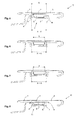
- Figure 5 Figure 6 and Figure 7 each shows slightly different sectional views, which are different for different conceivable configurations along the in Figure 2 shown cutting line.
- the electronic functional element 11 comprises a printed film 4 to be backlit with a total of five imaging display and control panels, a spacer insert 5 - preferably in the form of compressible foam material with recesses over the display and control panels - for pressing and fixing the film 4, one with switching elements and / or printed circuit boards with light elements and electrodes of capacitive proximity switches, and a cover 7, which covers the electronic functional element 11 on the back and is held on the decorative part by screws.
- Figure 5 shows a sectional view of a first possible embodiment of the in Figure 1 and Figure 2 Motor vehicle trim shown.
- a functional part 1 made of a translucent second plastic material is surrounded by the first plastic material forming a carrier part 3 on the periphery in such a way that the functional part 1 and the carrier part 3 have a continuous, gap-free surface on the front side with the front sides of the functional part 1 and the carrier part continuously flush with one another 3 form.
- the thus jointly formed front side of the intermediate component is continuously covered with a third plastic material forming the decorative surface, which is preferably flooded in the injection molding tool as a cover layer 2 over the front sides of the functional and carrier parts or applied to the front sides in a separate painting or coating process.
- the back of the functional part 1 remains freely accessible.
- the functional part 1 protrudes from the back of the carrier part 3 with a structure 9 which forms a mounting frame for the cover housing 7.
- the embodiment shown is the penetration with which the second plastic material of the functional part 1 penetrates the first plastic material of the carrier part 3, the same width on the rear and the front, the penetration surface of the same size on the front and rear.
- the lateral contact surface between the carrier part 3 and the functional part 1 runs - seen from the rear of the carrier part to the front of the carrier part - largely continuously perpendicular to the front surface formed jointly by the carrier part and the functional part and covered with the third plastic material.
- the front penetration surface A, with which the functional part 1 penetrates the carrier part 3 on the front is therefore largely identical to the rear penetration surface A 'with which the functional part penetrates the carrier part from the rear.
- the front-side penetration surface A, with which the second plastic material forming the functional part 1 penetrates the first plastic material forming the carrier part 3 on the front side is smaller than the rear side Penetration area A 'with which the functional part penetrates the carrier part from the rear.
- a bevel is provided in the area of the transition from the rear penetration surface to the front penetration surface.
- the course of the lateral contact surface between the first and second plastic material kinks - viewed from the rear of the carrier part to the front of the carrier part and based on the material thickness of the carrier part in the area of the penetration - at an angle of approximately half the total penetration depth.
- a step is provided in the region of the transition from the rear penetration surface A 'to the front penetration surface A.
- the embodiments shown reduce the risk that scattered light will be clearly visible on the outside at the transition from the second to the first plastic material.
- the effective contact area between the functional part and the carrier part is in this way compared to the embodiment according to FIG Figure 5 effectively enlarged, which improves the connection between the support part and the functional part.
- the in Figure 3, Figure 4 and Figure 8 The embodiment shown provides that the functional part 1 is largely steplessly flush and / or gapless and / or not only on the front side to be provided with the third plastic material, but also on the rear side of the functional part and the rear side of the carrier part merge into one another without edges.
- the functional part thus forms a window that is in circumferential contact in the first plastic forming the carrier part 3.
- the circumferential contact surface that forms between the first plastic material and the second plastic material during production can also be used in the case of the in Figure 8 embodiment shown analogous to that in Figure 6 or Figure 7
- the design of the contact surface shown may be provided with a step or bevel.
- the cover 7 is preferably supported circumferentially on the carrier part 3 and not, as in FIG Figure 5, Figure 6 and Figure 7 , on the functional part, where, as in Figure 8 shown, a circumferential seal and / or adhesive 8 is provided between the cover 7 and the back of the carrier part.
- a seal and / or bonding can of course also be used for the in Figure 5, Figure 6 and Figure 7 Embodiments shown between the functional part and cover, in particular between structure 9 and cover 7, are provided.
Landscapes
- Engineering & Computer Science (AREA)
- Manufacturing & Machinery (AREA)
- Mechanical Engineering (AREA)
- Injection Moulding Of Plastics Or The Like (AREA)
Priority Applications (1)
| Application Number | Priority Date | Filing Date | Title |
|---|---|---|---|
| EP19168421.6A EP3722065A1 (fr) | 2019-04-10 | 2019-04-10 | Pièce de garniture de véhicule automobile et son procédé de fabrication |
Applications Claiming Priority (1)
| Application Number | Priority Date | Filing Date | Title |
|---|---|---|---|
| EP19168421.6A EP3722065A1 (fr) | 2019-04-10 | 2019-04-10 | Pièce de garniture de véhicule automobile et son procédé de fabrication |
Publications (2)
| Publication Number | Publication Date |
|---|---|
| EP3722065A1 EP3722065A1 (fr) | 2020-10-14 |
| EP3722065A9 true EP3722065A9 (fr) | 2020-11-25 |
Family
ID=66105058
Family Applications (1)
| Application Number | Title | Priority Date | Filing Date |
|---|---|---|---|
| EP19168421.6A Withdrawn EP3722065A1 (fr) | 2019-04-10 | 2019-04-10 | Pièce de garniture de véhicule automobile et son procédé de fabrication |
Country Status (1)
| Country | Link |
|---|---|
| EP (1) | EP3722065A1 (fr) |
Cited By (1)
| Publication number | Priority date | Publication date | Assignee | Title |
|---|---|---|---|---|
| DE102021133452A1 (de) | 2021-12-16 | 2023-06-22 | Preh Gmbh | Dekorteil mit lichtdurchlässiger Blende und optisch unauffälliger Befestigung am Träger |
Family Cites Families (10)
| Publication number | Priority date | Publication date | Assignee | Title |
|---|---|---|---|---|
| JPS6021849B2 (ja) * | 1981-06-09 | 1985-05-29 | 東芝機械株式会社 | 多色成形用金型 |
| DE4433580A1 (de) | 1994-09-21 | 1996-03-28 | Kammerer Gmbh M | Verfahren zum Herstellen eines Anzeigefeldes |
| DE19722551A1 (de) * | 1997-05-28 | 1998-12-03 | Hohe Gmbh & Co Kg | Verfahren zur Herstellung von Kunststoffteilen in einem Zwei-Komponenten-Spritzgußprozeß |
| DE19934951A1 (de) | 1999-07-26 | 2001-02-01 | Mannesmann Vdo Ag | Mehrkomponenten-Kunststoffspritzgußteil mit optischer Anzeigefunktion |
| DE102004039004A1 (de) | 2004-08-11 | 2006-02-23 | Bayerische Motoren Werke Ag | Kraftfahrzeugleuchte mit einer aus Kunststoff gefertigten Lichtscheibe |
| DE102007024529A1 (de) * | 2007-05-24 | 2008-11-27 | Novem Car Interior Design Gmbh | Spritzpressverfahren zur Herstellung von Formteilen, insbesondere Dekorteilen und/oder Verkleidungsteilen für den Fahrzeuginnenraum |
| US8998282B2 (en) | 2009-04-07 | 2015-04-07 | Dura Automotive Body & Glass Systems Gmbh | Trim for a motor vehicle |
| EP2322962A1 (fr) | 2009-11-17 | 2011-05-18 | Weidmann Plastics Technology AG | Elément de décor doté d'un conducteur lumineux |
| DE102012211951A1 (de) | 2012-07-09 | 2014-01-09 | Wiegand Gmbh | Zierteil für Kraftfahrzeuge und Verfahren zu seiner Herstellung |
| DE102015220853B4 (de) | 2015-10-26 | 2023-09-28 | Bayerische Motoren Werke Aktiengesellschaft | Oberflächenelement für einen Kraftwagen |
-
2019
- 2019-04-10 EP EP19168421.6A patent/EP3722065A1/fr not_active Withdrawn
Cited By (1)
| Publication number | Priority date | Publication date | Assignee | Title |
|---|---|---|---|---|
| DE102021133452A1 (de) | 2021-12-16 | 2023-06-22 | Preh Gmbh | Dekorteil mit lichtdurchlässiger Blende und optisch unauffälliger Befestigung am Träger |
Also Published As
| Publication number | Publication date |
|---|---|
| EP3722065A1 (fr) | 2020-10-14 |
Similar Documents
| Publication | Publication Date | Title |
|---|---|---|
| EP4000058B1 (fr) | Composant comportant une pièce de base, une pièce supplémentaire et une couche de revêtement en laque et procédé de fabrication d'un tel composant | |
| EP2529912B1 (fr) | Support fonctionnel avec fonctions de touches | |
| EP2684744B1 (fr) | Pièce décorative pour véhicules automobiles ainsi que son procédé de fabrication | |
| EP1511049B1 (fr) | Méthode de fabrication des touches et de tableau de bord et bouton de commande fabriqué avec cette méthode | |
| DE102007015625B4 (de) | Verfahren zur Herstellung galvanisch beschichteter Bauteile mit durchleuchtbaren oder unbeleuchteten Strukturen und nach dem Verfahren hergestellte Bedien-, Dekor- oder Anzeigeelemente | |
| WO2011029207A1 (fr) | Procédé de production d'un composant présentant un élément décoratif plan, et composant doté d'un élément décoratif plan | |
| EP3048015B1 (fr) | Piece de formage, en particulier piece decorative et/ou piece d'habillage conçue comme une piece de formage pour l'espace interieur d'un vehicule et procede de fabrication de piece de formage | |
| EP3088156B1 (fr) | Procede de fabrication d'une piece rapportee pouvant etre eclairee, piece rapportee pouvant etre eclairee et vehicule automobile la comprenant | |
| DE102007052849A1 (de) | Teilweise verchrombare Vorrichtung und Verfahren zu deren Herstellung | |
| DE202011103932U1 (de) | Gehäuseschale, für insbesondere portable elektrische Geräte | |
| CH708048A2 (de) | Funktionsträger mit Tastenfunktionen. | |
| EP3866147A1 (fr) | Matériau composite décoratif pouvant être rétroéclairé, en particulier destiné au montage à l'intérieur des véhicules automobile | |
| DE102018127896B4 (de) | Verfahren zum Herstellen einer weichen oberen Verkleidung für eine Schalterbaugruppe einer Fahrzeugtür | |
| DE202016100258U1 (de) | Formteil, insbesondere als Formteil ausgebildetes Dekorteil und/oder Verkleidungsteil für einen Fahrzeuginnenraum | |
| DE102018127894A1 (de) | Weiche obere Verkleidung für eine Schalterbaugruppe einer Fahrzeugtür und Verfahren zum Herstellen dieser | |
| EP4019338A1 (fr) | Partie de revêtement extérieur partiellement translucide pour un véhicule automobile et procédé de fabrication d'une partie de revêtement extérieur | |
| WO2004099460A2 (fr) | Procede pour produire des corps moules eventuellement illuminables par transparence, ameliores galvaniquement, en thermoplastique, thermodurcissable, elastomere ou silicone, ainsi que corps moules eventuellement illuminables par transparence en thermoplastique, thermodurcissable, elastomere ou silicone a surface galvaniquem | |
| EP4344949B1 (fr) | Système d'éclairage pour un élément d'habillage extérieur d'un véhicule automobile | |
| DE102014013564A1 (de) | Verfahren zur Herstellung eines umgeformten Schaltungsträgers, sowie umgeformter Schaltungsträger | |
| DE102005023440A1 (de) | Anzeige- und/oder Bedienungspaneel | |
| EP3722065A9 (fr) | Pièce de garniture de véhicule automobile et son procédé de fabrication | |
| DE10329259B4 (de) | Kunststoffformteil für Kraftfahrzeuginnenräume und Herstellungsverfahren | |
| EP3257649B1 (fr) | Procédé de fabrication d'un revêtement en plastique comprenant une partie transparente et recouvrement d'affichage en plastique | |
| DE102016214268A1 (de) | Blende zur Innenausstattung eines Kraftfahrzeugs, Verfahren zum Herstellen einer Blende und Kraftfahrzeug | |
| DE202020002576U1 (de) | Selektiv verchromte und hintergrundbeleuchtbare Fahrzeugkomponente |
Legal Events
| Date | Code | Title | Description |
|---|---|---|---|
| PUAI | Public reference made under article 153(3) epc to a published international application that has entered the european phase |
Free format text: ORIGINAL CODE: 0009012 |
|
| STAA | Information on the status of an ep patent application or granted ep patent |
Free format text: STATUS: THE APPLICATION HAS BEEN PUBLISHED |
|
| AK | Designated contracting states |
Kind code of ref document: A1 Designated state(s): AL AT BE BG CH CY CZ DE DK EE ES FI FR GB GR HR HU IE IS IT LI LT LU LV MC MK MT NL NO PL PT RO RS SE SI SK SM TR |
|
| AX | Request for extension of the european patent |
Extension state: BA ME |
|
| STAA | Information on the status of an ep patent application or granted ep patent |
Free format text: STATUS: REQUEST FOR EXAMINATION WAS MADE |
|
| 17P | Request for examination filed |
Effective date: 20210414 |
|
| RBV | Designated contracting states (corrected) |
Designated state(s): AL AT BE BG CH CY CZ DE DK EE ES FI FR GB GR HR HU IE IS IT LI LT LU LV MC MK MT NL NO PL PT RO RS SE SI SK SM TR |
|
| TPAC | Observations filed by third parties |
Free format text: ORIGINAL CODE: EPIDOSNTIPA |
|
| TPAC | Observations filed by third parties |
Free format text: ORIGINAL CODE: EPIDOSNTIPA |
|
| STAA | Information on the status of an ep patent application or granted ep patent |
Free format text: STATUS: EXAMINATION IS IN PROGRESS |
|
| 17Q | First examination report despatched |
Effective date: 20220509 |
|
| RAP1 | Party data changed (applicant data changed or rights of an application transferred) |
Owner name: PLASMAN EUROPE AB |
|
| TPAC | Observations filed by third parties |
Free format text: ORIGINAL CODE: EPIDOSNTIPA |
|
| STAA | Information on the status of an ep patent application or granted ep patent |
Free format text: STATUS: THE APPLICATION IS DEEMED TO BE WITHDRAWN |
|
| 18D | Application deemed to be withdrawn |
Effective date: 20241101 |